WO2011089716A1 - Treatment tool, treatment device, and treatment method - Google Patents
Treatment tool, treatment device, and treatment method Download PDFInfo
- Publication number
- WO2011089716A1 WO2011089716A1 PCT/JP2010/050839 JP2010050839W WO2011089716A1 WO 2011089716 A1 WO2011089716 A1 WO 2011089716A1 JP 2010050839 W JP2010050839 W JP 2010050839W WO 2011089716 A1 WO2011089716 A1 WO 2011089716A1
- Authority
- WO
- WIPO (PCT)
- Prior art keywords
- holding member
- energy
- treatment
- fluid
- living
- Prior art date
Links
Images


Classifications
-
- A—HUMAN NECESSITIES
- A61—MEDICAL OR VETERINARY SCIENCE; HYGIENE
- A61B—DIAGNOSIS; SURGERY; IDENTIFICATION
- A61B18/00—Surgical instruments, devices or methods for transferring non-mechanical forms of energy to or from the body
- A61B18/04—Surgical instruments, devices or methods for transferring non-mechanical forms of energy to or from the body by heating
- A61B18/12—Surgical instruments, devices or methods for transferring non-mechanical forms of energy to or from the body by heating by passing a current through the tissue to be heated, e.g. high-frequency current
- A61B18/14—Probes or electrodes therefor
- A61B18/1442—Probes having pivoting end effectors, e.g. forceps
- A61B18/1445—Probes having pivoting end effectors, e.g. forceps at the distal end of a shaft, e.g. forceps or scissors at the end of a rigid rod
-
- A—HUMAN NECESSITIES
- A61—MEDICAL OR VETERINARY SCIENCE; HYGIENE
- A61B—DIAGNOSIS; SURGERY; IDENTIFICATION
- A61B18/00—Surgical instruments, devices or methods for transferring non-mechanical forms of energy to or from the body
- A61B18/04—Surgical instruments, devices or methods for transferring non-mechanical forms of energy to or from the body by heating
- A61B18/08—Surgical instruments, devices or methods for transferring non-mechanical forms of energy to or from the body by heating by means of electrically-heated probes
- A61B18/082—Probes or electrodes therefor
- A61B18/085—Forceps, scissors
-
- A—HUMAN NECESSITIES
- A61—MEDICAL OR VETERINARY SCIENCE; HYGIENE
- A61B—DIAGNOSIS; SURGERY; IDENTIFICATION
- A61B18/00—Surgical instruments, devices or methods for transferring non-mechanical forms of energy to or from the body
- A61B18/18—Surgical instruments, devices or methods for transferring non-mechanical forms of energy to or from the body by applying electromagnetic radiation, e.g. microwaves
- A61B18/1815—Surgical instruments, devices or methods for transferring non-mechanical forms of energy to or from the body by applying electromagnetic radiation, e.g. microwaves using microwaves
-
- A—HUMAN NECESSITIES
- A61—MEDICAL OR VETERINARY SCIENCE; HYGIENE
- A61B—DIAGNOSIS; SURGERY; IDENTIFICATION
- A61B18/00—Surgical instruments, devices or methods for transferring non-mechanical forms of energy to or from the body
- A61B18/18—Surgical instruments, devices or methods for transferring non-mechanical forms of energy to or from the body by applying electromagnetic radiation, e.g. microwaves
- A61B18/20—Surgical instruments, devices or methods for transferring non-mechanical forms of energy to or from the body by applying electromagnetic radiation, e.g. microwaves using laser
-
- A—HUMAN NECESSITIES
- A61—MEDICAL OR VETERINARY SCIENCE; HYGIENE
- A61B—DIAGNOSIS; SURGERY; IDENTIFICATION
- A61B18/00—Surgical instruments, devices or methods for transferring non-mechanical forms of energy to or from the body
- A61B2018/00053—Mechanical features of the instrument of device
- A61B2018/0016—Energy applicators arranged in a two- or three dimensional array
-
- A—HUMAN NECESSITIES
- A61—MEDICAL OR VETERINARY SCIENCE; HYGIENE
- A61B—DIAGNOSIS; SURGERY; IDENTIFICATION
- A61B18/00—Surgical instruments, devices or methods for transferring non-mechanical forms of energy to or from the body
- A61B2018/00571—Surgical instruments, devices or methods for transferring non-mechanical forms of energy to or from the body for achieving a particular surgical effect
- A61B2018/0063—Sealing
-
- A—HUMAN NECESSITIES
- A61—MEDICAL OR VETERINARY SCIENCE; HYGIENE
- A61B—DIAGNOSIS; SURGERY; IDENTIFICATION
- A61B18/00—Surgical instruments, devices or methods for transferring non-mechanical forms of energy to or from the body
- A61B2018/00636—Sensing and controlling the application of energy
- A61B2018/00773—Sensed parameters
- A61B2018/00869—Phase
-
- A—HUMAN NECESSITIES
- A61—MEDICAL OR VETERINARY SCIENCE; HYGIENE
- A61B—DIAGNOSIS; SURGERY; IDENTIFICATION
- A61B18/00—Surgical instruments, devices or methods for transferring non-mechanical forms of energy to or from the body
- A61B2018/00636—Sensing and controlling the application of energy
- A61B2018/00773—Sensed parameters
- A61B2018/00875—Resistance or impedance
-
- A—HUMAN NECESSITIES
- A61—MEDICAL OR VETERINARY SCIENCE; HYGIENE
- A61B—DIAGNOSIS; SURGERY; IDENTIFICATION
- A61B18/00—Surgical instruments, devices or methods for transferring non-mechanical forms of energy to or from the body
- A61B18/04—Surgical instruments, devices or methods for transferring non-mechanical forms of energy to or from the body by heating
- A61B18/12—Surgical instruments, devices or methods for transferring non-mechanical forms of energy to or from the body by heating by passing a current through the tissue to be heated, e.g. high-frequency current
- A61B18/14—Probes or electrodes therefor
- A61B18/1442—Probes having pivoting end effectors, e.g. forceps
- A61B2018/1452—Probes having pivoting end effectors, e.g. forceps including means for cutting
- A61B2018/1455—Probes having pivoting end effectors, e.g. forceps including means for cutting having a moving blade for cutting tissue grasped by the jaws
-
- A—HUMAN NECESSITIES
- A61—MEDICAL OR VETERINARY SCIENCE; HYGIENE
- A61B—DIAGNOSIS; SURGERY; IDENTIFICATION
- A61B2218/00—Details of surgical instruments, devices or methods for transferring non-mechanical forms of energy to or from the body
- A61B2218/001—Details of surgical instruments, devices or methods for transferring non-mechanical forms of energy to or from the body having means for irrigation and/or aspiration of substances to and/or from the surgical site
- A61B2218/002—Irrigation
-
- A—HUMAN NECESSITIES
- A61—MEDICAL OR VETERINARY SCIENCE; HYGIENE
- A61N—ELECTROTHERAPY; MAGNETOTHERAPY; RADIATION THERAPY; ULTRASOUND THERAPY
- A61N7/00—Ultrasound therapy
- A61N7/02—Localised ultrasound hyperthermia
- A61N2007/025—Localised ultrasound hyperthermia interstitial
Definitions
- the present invention relates to a therapeutic treatment tool, a therapeutic treatment apparatus, and a therapeutic treatment method for treating / treating a biological tissue.
- biological tissues are obtained by (1) bringing biological tissues to be joined together into contact with each other, (2) denaturing proteins in the target tissues, and (3) removing moisture existing between the target tissues, It is known that it can be joined.
- This is a bond using a so-called hydrogen bond, which is a bond using the polarity of the polar group of the amino acid constituting the protein.
- denaturing a protein means changing the three-dimensional structure, which is one of the characteristics of the protein, that is, dissociating bonds between polar groups that are bonded with a certain regularity to form the three-dimensional structure. It means that. It becomes possible to promote the new bond with the polar group existing in the adjacent protein using the polar group which is freed by dissociating the bond between the polar groups. It becomes possible to cause joining.
- medical treatment tools use various energies such as high frequency, heat, ultrasonic waves, and laser light. By utilizing these energies, the temperature of the tissue to be joined is increased, and protein denaturation and moisture (H 2 O) existing between the target tissues are simultaneously performed. This achieves tissue bonding.
- An energy device currently used as a blood vessel sealing device also utilizes this phenomenon.
- the water molecule H 2 O is easily bonded to a molecule having a polar group because of its strong polarity. That is, it easily binds to a protein having a polar group. This makes it difficult to join tissues in the presence of water molecules H 2 O.
- tissue bonding it can be said that removing water molecules H 2 O existing between tissues to be bonded is a condition for achieving stable and strong bonding.
- the water molecule H 2 O present around the junction has a strong polarity as described above, and easily binds to a polar group present around. This is not an exception even if the polar group is once bonded to another polar group.
- the water molecule H 2 O itself binds to the already completed bond. For this reason, the bonds between proteins are dissociated, and when viewed macroscopically, the bonding strength between living tissues decreases with time.
- the present invention prevents a moisture from entering a joint part between living tissues and maintains a state where the living tissues are in close contact with each other for a long time, that is, a therapeutic treatment tool and a treatment capable of maintaining the strength of the joint part well.
- An object of the present invention is to provide a treatment device and a therapeutic treatment method.
- the therapeutic treatment tool for joining living tissues is provided on at least one of the pair of holding members that hold the living tissue to be treated and at least one of the pair of holding members.
- an energy output unit connected to an energy source, supplying energy to the living tissue held by the pair of holding members to join the living tissues together to form a joined portion, and after forming the joined portion, And a discharge part for releasing the substance so as to cover a surface layer of the joint part of the living tissue with a substance that prevents permeation of moisture into the joint part.
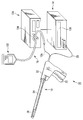
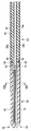
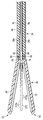
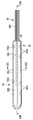
- FIG. 1 is a schematic view showing a therapeutic treatment system according to the first embodiment.
- FIG. 2 is a schematic block diagram showing the therapeutic treatment system according to the first embodiment.
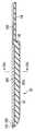
- FIG. 3A is a schematic longitudinal sectional view showing a closed treatment portion and a shaft of the bipolar type energy treatment device of the medical treatment system according to the first embodiment.
- FIG. 3B is a schematic longitudinal sectional view showing an open treatment portion and a shaft of the energy treatment device of the medical treatment system according to the first embodiment.
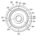
- 4A shows a first holding member of the treatment portion of the energy treatment device of the medical treatment system according to the first embodiment, and is a schematic plan view seen from the direction of the arrow 4A in FIGS. 4B and 4C. is there.
- FIG. 1 is a schematic view showing a therapeutic treatment system according to the first embodiment.
- FIG. 2 is a schematic block diagram showing the therapeutic treatment system according to the first embodiment.
- FIG. 3A is a schematic longitudinal sectional view showing a closed treatment portion and a shaft of the
- FIG. 4B shows a first holding member of the treatment portion of the energy treatment device of the medical treatment system according to the first embodiment, and is a schematic longitudinal section taken along line 4B-4B in FIG. 4A and FIG. 4C.
- FIG. 4C shows a first holding member of the treatment portion of the energy treatment device of the medical treatment system according to the first embodiment, and is a schematic cross-section along line 4C-4C in FIGS. 4A and 4B.
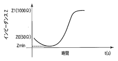
- FIG. FIG. 5A shows the time and impedance shown when high-frequency energy is applied to the held biological tissue in a state where the biological tissue is held by the treatment unit of the energy treatment device of the therapeutic treatment system according to the first embodiment. It is a schematic graph which shows the relationship of these.
- FIG. 5A shows the time and impedance shown when high-frequency energy is applied to the held biological tissue in a state where the biological tissue is held by the treatment unit of the energy treatment device of the therapeutic treatment system according to the first embodiment. It is a schematic graph which shows the relationship of these.
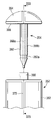
- FIG. 5B is a schematic perspective view showing a state of a living tissue immediately after performing a treatment using the energy treatment device of the medical treatment system according to the first embodiment.
- FIG. 6 shows a medical treatment performed by an energy source, a foot switch, and a fluid source when a living tissue is joined using the therapeutic treatment system according to the first embodiment and an outer periphery of the joined living tissue is coated. It is a flowchart which shows the control state of a treatment system.
- FIG. 7 shows a time when high-frequency energy is applied to the held biological tissue in a state where the biological tissue is held by the treatment unit of the energy treatment device of the therapeutic treatment system according to the modification of the first embodiment. It is a schematic graph which shows the relationship between and a phase difference.
- FIG. 6 shows a medical treatment performed by an energy source, a foot switch, and a fluid source when a living tissue is joined using the therapeutic treatment system according to the first embodiment and an outer periphery of the joined living tissue is coated.
- It is a flowchar
- FIG. 8 shows a therapeutic treatment system according to a modification of the first embodiment, and is a schematic block diagram in the case where treatment is performed using a change in phase difference as a threshold for supplying / stopping high-frequency energy. is there.
- FIG. 9 is a schematic diagram showing a state in which a living tissue is treated using the monopolar type energy treatment tool of the medical treatment system according to the modification of the first embodiment.
- FIG. 10 is a schematic diagram showing a therapeutic treatment system according to a modification of the first embodiment.
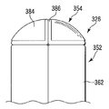
- FIG. 11A shows a first holding member of the treatment portion of the energy treatment device of the medical treatment system according to the second embodiment, and is a schematic plan view seen from the direction of arrow 11A in FIGS. 11B and 11C. is there.
- FIG. 11A shows a first holding member of the treatment portion of the energy treatment device of the medical treatment system according to the second embodiment, and is a schematic plan view seen from the direction of arrow 11A in FIGS. 11B and 11C. is there.
- FIG. 11B shows a first holding member of the treatment portion of the energy treatment device of the medical treatment system according to the second embodiment, and is a schematic longitudinal section taken along the line 11B-11B in FIG. 11A and FIG. 11C.
- FIG. 11C shows a first holding member of the treatment portion of the energy treatment device of the medical treatment system according to the second embodiment, and shows a schematic crossing along the line 11C-11C in FIG. 11A and FIG. 11B.
- FIG. FIG. 12 is a schematic diagram showing a therapeutic treatment system according to the third embodiment.
- FIG. 13 is a schematic block diagram showing a medical treatment system according to the third embodiment.
- FIG. 14A shows a first holding member of the treatment portion of the energy treatment device of the medical treatment system according to the third embodiment, and is a schematic plan view seen from the direction of arrow 14A in FIGS. 14B and 14C. is there.
- FIG. 14B shows a first holding member of the treatment portion of the energy treatment device of the medical treatment system according to the third embodiment, and is a schematic longitudinal cross section taken along the line 14B-14B in FIG. 14A and FIG. 14C.
- FIG. FIG. 14C shows a first holding member of the treatment portion of the energy treatment device of the medical treatment system according to the third embodiment, and is a schematic cross-section along the line 14C-14C in FIG. 14A and FIG. 14B.
- FIG. 15A is a schematic longitudinal sectional view showing a closed treatment portion and a shaft of a bipolar type energy treatment device of the treatment system according to the third embodiment.
- FIG. 15B is a schematic longitudinal sectional view showing an open treatment portion and a shaft of the energy treatment device of the medical treatment system according to the third embodiment.
- FIG. 16 shows a medical treatment performed by an energy source, a foot switch, and a fluid source when a living tissue is joined using the therapeutic treatment system according to the third embodiment and an outer periphery of the joined living tissue is coated. It is a flowchart which shows the control state of a treatment system.
- FIG. 17 is a schematic perspective view showing a state of a living tissue immediately after performing a treatment using the energy treatment device of the medical treatment system according to the third embodiment.
- FIG. 18A shows a first holding member of the treatment portion of the energy treatment device of the medical treatment system according to the fourth embodiment, and is a schematic plan view seen from the direction of the arrow 18A in FIGS. 18B and 18C. is there.
- FIG. 18B shows a first holding member of the treatment portion of the energy treatment device of the medical treatment system according to the fourth embodiment, and is a schematic longitudinal cross section taken along the line 18B-18B in FIG. 18A and FIG. 18C.
- FIG. FIG. 18C shows a first holding member of the treatment portion of the energy treatment device of the medical treatment system according to the fourth embodiment, and is a schematic cross-section along the line 18C-18C in FIG. 18A and FIG. 18B.
- FIG. 18D is a schematic perspective view showing a protrusion disposed on the high-frequency electrode of the first holding member of the treatment portion of the energy treatment device of the medical treatment system according to the fourth embodiment.
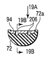
- FIG. 19A shows a second holding member of the treatment portion of the energy treatment device of the medical treatment system according to the fourth embodiment, and is a schematic plan view seen from the direction of the arrow 19A in FIGS. 19B and 19C. is there.
- FIG. 19B shows a second holding member of the treatment portion of the energy treatment device of the medical treatment system according to the fourth embodiment, and is a schematic longitudinal cross section taken along the line 19B-19B in FIG. 19A and FIG. 19C.
- FIG. 19C shows a second holding member of the treatment portion of the energy treatment device of the medical treatment system according to the fourth embodiment, and is a schematic cross-section along the line 19C-19C in FIG. 19A and FIG. 19B.
- FIG. FIG. 20 is a schematic perspective view showing a state of a living tissue immediately after performing a treatment using the energy treatment device of the medical treatment system according to the fourth embodiment.
- FIG. 21A is a schematic plan view showing the first holding member of the treatment portion of the energy treatment device of the medical treatment system according to the fifth embodiment, viewed from the direction of arrow 21A in FIG. 21B.
- FIG. 21B is a schematic cross-sectional view taken along line 21B-21B in FIG.
- FIG. 22A is a schematic perspective view showing a distal end portion including a blade portion of a cutter disposed in an energy treatment device of a medical treatment system according to a fifth embodiment.
- FIG. 22B is a schematic cross-sectional view showing a cutter disposed in the energy treatment device of the medical treatment system according to the fifth embodiment.
- FIG. 22C is a schematic diagram showing a state in which a living tissue is bonded and held by a treatment portion of an energy treatment device of a medical treatment system according to a fifth embodiment, and the living tissue is cut with a cutter. It is a cross-sectional view.
- FIG. 22A is a schematic perspective view showing a distal end portion including a blade portion of a cutter disposed in an energy treatment device of a medical treatment system according to a fifth embodiment.
- FIG. 22B is a schematic cross-sectional view showing a cutter disposed in the energy treatment device of the medical treatment system according to the fifth embodiment.
- FIG. 22C is a schematic diagram showing a state in
- FIG. 22D is a schematic perspective view showing a state of a living tissue immediately after performing a treatment using the energy treatment device of the medical treatment system according to the fifth embodiment.
- FIG. 23 is a flowchart showing a control state of the therapeutic treatment system performed by an energy source, a foot switch, and a fluid source when treating a living tissue using the therapeutic treatment system according to the fifth embodiment.
- FIG. 24A is a schematic perspective view showing a distal end portion including a blade portion of a cutter disposed in an energy treatment device of a medical treatment system according to a sixth embodiment.
- FIG. 24B is a schematic cross-sectional view showing a cutter disposed in the energy treatment device of the medical treatment system according to the sixth embodiment.
- FIG. 24C is a schematic cross-sectional view showing a state in which a living tissue is joined and held by a treatment portion of the energy treatment device of the medical treatment system according to the sixth embodiment and cut by a cutter.
- FIG. 24D is a schematic perspective view showing a state of a living tissue immediately after performing a treatment using the energy treatment device of the medical treatment system according to the sixth embodiment.
- FIG. 25A is a schematic view showing a therapeutic treatment system according to a seventh embodiment.
- FIG. 25B is a schematic partial longitudinal sectional view showing the handle of the energy treatment device of the medical treatment system according to the seventh embodiment.
- FIG. 26 is a schematic block diagram showing a medical treatment system according to the seventh embodiment.
- FIG. 27A is a schematic longitudinal sectional view showing a closed treatment portion and a shaft of a bipolar type energy treatment device of the medical treatment system according to the seventh embodiment.
- FIG. 27B is a schematic longitudinal sectional view showing an open treatment portion and a shaft of the energy treatment device of the medical treatment system according to the seventh embodiment.
- FIG. 28A is a schematic plan view showing a first holding member of the treatment portion of the energy treatment device of the medical treatment system according to the seventh embodiment.
- FIG. 28B shows a first holding member of the treatment portion of the energy treatment device of the medical treatment system according to the seventh embodiment, and is a schematic cross section taken along line 28B-28B in FIGS. 27A and 28A.
- FIG. 29 is a schematic partial longitudinal sectional view showing a modification of the handle of the energy treatment device of the medical treatment system according to the seventh embodiment.
- FIG. 30A shows a first holding member of the treatment portion of the energy treatment device of the medical treatment system according to the eighth embodiment, and is a schematic plan view seen from the direction of arrow 30A in FIGS. 30B and 30C. is there.
- FIG. 30B shows a first holding member of the treatment portion of the energy treatment device of the medical treatment system according to the eighth embodiment, and is a schematic longitudinal cross section taken along the line 30B-30B in FIG. 30A and FIG. 30C.
- FIG. 30C shows a first holding member of the treatment portion of the energy treatment device of the medical treatment system according to the eighth embodiment, and shows a schematic crossing along the line 30C-30C in FIG. 30A and FIG. 30B.
- FIG. FIG. 31 is a schematic view showing a medical treatment system according to the ninth embodiment.
- FIG. 32A is a schematic front view showing a state where the main body side holding member and the detachable side holding member are separated from each other in the treatment portion of the bipolar type energy treatment device of the medical treatment system according to the ninth embodiment. is there.
- FIG. 32B shows a state in which the main body side holding member and the detachable side holding member are separated from each other of the treatment portion of the energy treatment device of the medical treatment system according to the ninth embodiment.
- FIG. 33 is a schematic plan view showing the main body side holding member of the treatment portion of the energy treatment device of the medical treatment system according to the ninth embodiment, viewed from the direction of arrow 33 in FIG. 32A.
- FIG. 34A is a schematic front view showing a state where the main body side holding member and the detachable side holding member are closed in the treatment portion of the bipolar type energy treatment device of the medical treatment system according to the ninth embodiment. is there.
- FIG. 34B is a schematic longitudinal sectional view showing a state in which the main body side holding member and the detachable side holding member are opened in the treatment portion of the bipolar type energy treatment device of the medical treatment system according to the ninth embodiment. It is.
- FIG. 34A is a schematic front view showing a state where the main body side holding member and the detachable side holding member are closed in the treatment portion of the bipolar type energy treatment device of the medical treatment system according to the ninth embodiment. It is.
- FIG. 34B is a schematic longitudinal sectional view showing a state in which
- FIG. 35A is a schematic front view showing a state where the main body side holding member and the detachable side holding member are separated from each other in the treatment portion of the bipolar type energy treatment device of the medical treatment system according to the tenth embodiment. is there.
- FIG. 35B shows a state where the main body side holding member and the detachable side holding member are separated from each other of the treatment section of the energy treatment device of the medical treatment system according to the tenth embodiment. It is a schematic longitudinal cross-sectional view which follows this.
- FIG. 36 is a schematic plan view showing the main body side holding member of the treatment portion of the energy treatment device of the medical treatment system according to the tenth embodiment, viewed from the direction of the arrow 36 in FIG. 35B.
- FIG. 37A is a schematic front view showing a state in which the main body side holding member and the detachable side holding member are closed in the treatment portion of the bipolar type energy treatment device of the medical treatment system according to the tenth embodiment. is there.
- FIG. 37B is a schematic longitudinal sectional view showing a state in which the main body side holding member and the detachable side holding member are opened in the treatment portion of the bipolar type energy treatment device of the medical treatment system according to the tenth embodiment. It is.
- FIG. 37C is a schematic perspective view showing protrusions disposed on the high-frequency electrode of the detachable side holding member of the energy treatment device of the medical treatment system according to the tenth embodiment.
- a first embodiment will be described with reference to FIGS.
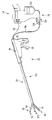
- an energy treatment tool for example, a linear type surgical treatment tool 12 for performing a treatment through the abdominal wall will be described.
- the treatment system 10 includes an energy treatment instrument 12, an energy source (control unit) 14, a foot switch (may be a hand switch) 16 (see FIG. 2), a fluid source. 18.
- the energy treatment device 12 includes a handle 22, a shaft 24, and a treatment part (holding part) 26 that can be opened and closed.
- the handle 22 is connected to the energy source 14 via a cable 28.
- a foot switch 16 is connected to the energy source 14.
- the foot switch 16 has a pedal (not shown). By operating (pressing / depressing) the pedal of the foot switch 16, the supply of energy (high-frequency energy in this embodiment) from the energy source 14 to the surgical treatment instrument 12 is turned ON / OFF. A series of operations of whether or not to flow a fluid (joining aid) described later is switched.
- the pedal When the pedal is being pressed, the high-frequency energy is output based on a state in which the high-frequency energy is appropriately set (a state in which the energy output amount, energy output timing, etc. are controlled).
- the pedal is released, the output of the high frequency energy is forcibly stopped. Further, when the pedal is pressed, a predetermined flow rate of fluid flows, and when the press is released, the fluid flow stops.
- the handle 22 is formed in a shape that is easy for an operator to grip, and is formed in, for example, a substantially L shape.
- a shaft 24 is disposed at one end of the handle 22.
- the cable 28 described above extends from the proximal end of the handle 22 coaxial with the shaft 24.
- energization lines 28a and 28b of high-frequency electrodes 92 and 94 described later are inserted.
- the other end side of the handle 22 is a grasping portion that extends in a direction away from the axial direction of the shaft 24 and is grasped by the operator.
- the handle 22 is provided with a treatment section opening / closing knob 32 so as to be juxtaposed on the other end side.
- the treatment portion opening / closing knob 32 is connected to a proximal end of a sheath 44 (see FIGS. 3A and 3B) described later of the shaft 24 at a substantially central portion of the handle 22.
- the sheath 44 moves along the axial direction thereof.
- the shaft 24 includes a cylindrical body 42 and a sheath 44 slidably disposed on the outer side of the cylindrical body 42.
- the cylindrical body 42 has a proximal end portion fixed to the handle 22 (see FIG. 1).
- the sheath 44 is slidable along the axial direction of the cylindrical body 42.
- a recess 46 is formed on the outer side of the cylindrical body 42 along the axial direction thereof.
- An electrode energization line 28 a connected to a high-frequency electrode (energy output unit) 92 described later is disposed in the recess 46.
- An electrode energization line 28 b connected to a high-frequency electrode (energy output unit) 94 described later is inserted into the cylindrical body 42.
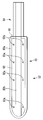
- the treatment portion 26 is disposed at the tip of the shaft 24.
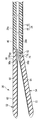
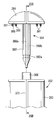
- the treatment section 26 includes a pair of holding members 52 and 54, that is, a first holding member (first jaw) 52 and a second holding member (second jaw). 54.
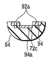
- the first holding member 52 includes a first holding member main body (hereinafter, mainly referred to as a main body) 62 and a base portion 64 provided at a base end portion of the main body 62.
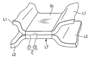
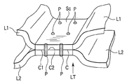
- the main body 62 is a portion that holds the living tissues L1 and L2 shown in FIG. 5B in cooperation with a main body 72 described later of the second holding member 54, and has a holding surface (edge) 62a.
- the base 64 is a part connected to the tip of the shaft 24.
- the main body 62 and the base 64 of the first holding member 52 are arranged coaxially.
- a step 66 is formed between the main body 62 and the base 64.
- a second holding member main body (hereinafter, mainly referred to as a main body) 72 and the main body And a base portion 74 provided at the base end portion of 72.
- the main body 72 is a part that holds the living tissues L1 and L2 in cooperation with the main body 62 of the first holding member 52, and has a holding surface (edge) 72a.
- the base 74 is a portion connected to the tip of the shaft 24.
- the main body 72 and the base portion 74 of the second holding member 54 are disposed coaxially.
- a step 76 is formed between the main body 72 and the base 74.
- the main body 62 of the first holding member 52 and the main body 72 of the second holding member 54 have the same shape. Further, the base portion 64 of the first holding member 52 and the base portion 74 of the second holding member 54 are pivotally supported by the cylindrical body 42 of the shaft 24 so that the base portion 74 of the second holding member 54 will be described later. Although the structure is different from the base 64 of the first holding member 52, the other structures are the same, and thus the description thereof is omitted as appropriate.
- the outer surface of the main body 62 of the first holding member 52 is formed in a smooth curved surface.
- the outer surface of the base 64 of the first holding member 52 is also formed in a smooth curved surface.
- the cross section of the treatment portion 26 is formed in a substantially circular shape or a substantially elliptic shape in the cross sections of the main bodies 62 and 72 and the base portions 64 and 74.
- the holding surfaces (edge portions) 62 a and 72 a of the main bodies 62 and 72 of the first and second holding members 52 and 54 face each other. And abut.
- the outer diameters of the base end portions of the main bodies 62 and 72 of the first and second holding members 52 and 54 are formed larger than the outer diameters of the base portions 64 and 74.
- the steps 66 and 76 described above are formed between the main bodies 62 and 72 and the bases 64 and 74, respectively.
- the base portion 64 of the first holding member 52 is fixed to the distal end portion of the cylindrical body 42 of the shaft 24.
- the base portion 74 of the second holding member 54 is rotatably supported on the tip end portion of the cylindrical body 42 of the shaft 24 by a support pin 82 disposed in a direction orthogonal to the axial direction of the shaft 24.
- the second holding member 54 can be opened and closed with respect to the first holding member 52 by rotating around the axis of the support pin 82.
- the second holding member 54 is urged by an elastic member 84 such as a leaf spring so as to open with respect to the first holding member 52.
- first and second holding members 52 and 54 are substantially circular or substantially combined with their base portions 64 and 74 in a state where the second holding member 54 is closed with respect to the first holding member 52.
- An elliptical outer peripheral surface is formed to be substantially flush with or slightly larger in diameter than the outer peripheral surface of the distal end portion of the cylindrical body 42. For this reason, the sheath 44 can be slid with respect to the cylindrical body 42, and the base portions 64 and 74 of the first holding member 52 and the second holding member 54 can be covered with the tip of the sheath 44.
- the second holding member 54 is closed with respect to the first holding member 52 against the urging force of the elastic member 84.
- the sheath 44 is slid to the proximal end side of the cylindrical body 42 from the state where the distal ends of the sheath 44 cover the base portions 64 and 74 of the first and second holding members 52 and 54, as shown in FIG.
- the second holding member 54 opens with respect to the first holding member 52 by the biasing force of the elastic member 84.
- the main bodies 62 and 72 of the first and second holding members 52 and 54 are preferably arranged in parallel with two rows of groove-shaped channels (channels) 62b and 72b. Is formed. That is, the flow paths 62b and 72b of the main bodies 62 and 72 are opened to the outside. The tips of the flow paths 62b and 72b are closed.
- Two rows of ducts 64a and 74a which are preferably parallel to each other, are formed in the bases 64 and 74, respectively. That is, the pipes 64a and 74a of the base portions 64 and 74 are closed to the outside except for both ends.
- the flow paths 62b and 72b of the main bodies 62 and 64 and the pipe lines 64a and 74a of the base parts 64 and 74 are formed continuously.
- the distal ends of flexible hoses 18a inserted into the shaft 24 are connected to the proximal ends of the pipes 64a and 74a of the base portions 64 and 74, respectively.
- the proximal end of the hose 18 a is extended to the outside of the energy treatment device 12 through the handle 22 and connected to the fluid source 18.
- a later-described fluid such as a liquid accumulated in the fluid source 18 passes through the hose 18a through the pipes 64a and 74a of the base portions 64 and 74 of the first and second holding members 52 and 54, and the flow path 62b of the main bodies 62 and 72. , 72b.
- the hose 18a is preferably made of a transparent or translucent flexible tube outside the energy treatment device 12. By using such a transparent or translucent tube, it can be visually recognized that the liquid flows.
- the hose 18a may be branched into two or four at positions close to the bases 64 and 74 of the first and second holding members 52 and 54 when the liquid is guided from the fluid source 18 to the treatment unit 26. preferable. Further, depending on the viscosity of the liquid guided from the fluid source 18 to the treatment section 26, the supply may be assisted using air pressure or the like when supplying the liquid to the first and second holding members 52 and 54 through the hose 18a. good.
- flat plate-like high-frequency electrodes are used as output members and energy discharge portions.
- 92 and 94 are arranged. These high-frequency electrodes 92 and 94 are electrically connected to the tips of energization lines 28a and 28b via connectors 96a and 96b.
- the energization lines 28a and 28b are connected to a high-frequency energy output unit 104, which will be described later, of the energy source 14. For this reason, by energizing the living tissues L1 and L2 held between the high-frequency electrodes 92 and 94 to generate Joule heat in the living tissues L1 and L2, the living tissues L1 and L2 themselves are heated and denatured.
- These high-frequency electrodes 92 and 94 cover the two rows of groove-like flow paths 62b and 72b of the main bodies 62 and 72, respectively, and these flow paths 62b and 72b are respectively formed as ducts.
- the high-frequency electrodes 92 and 94 are formed with a plurality of openings (joining maintenance auxiliary portions and discharge portions) 92a and 94a along the flow paths 62b and 72b. For this reason, the fluid from the fluid source 18 described above can ooze out from the openings 92a and 94a of the high-frequency electrodes 92 and 94.
- the openings 92a and 94a are preferably arranged, for example, at equal intervals or so as to allow the same amount of liquid to ooze from the openings 92a and 94a by adjusting the opening diameter.
- These high-frequency electrodes 92 and 94 are used to treat the living tissues L1 and L2 with high-frequency energy, and also have an impedance Z (see FIG. 5A) and a phase ⁇ (see FIG. 7) between the living tissues L1 and L2. It can be used as a sensor to measure.
- the high-frequency electrodes 92 and 94 can transmit and receive signals to the detection unit 106 described later of the energy source 14 through the energization lines 28a and 28b, for example.
- the impedance Z is measured by the detection unit 106.
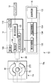
- the energy source 14 includes a first control unit (energy control unit) 102, a high-frequency energy output unit (first high-frequency energy output unit) 104, a detection unit 106, a display unit 108, And a speaker 110.
- the first control unit 102 is connected to a high-frequency energy output unit 104, a detection unit 106, a display unit 108, and a speaker 110.
- the first control unit 102 detects the high-frequency energy output unit 104 and detects it.
- the unit 106, the display unit 108, and the speaker 110 are controlled.
- the high-frequency energy output unit 104 generates energy and supplies the energy to the high-frequency electrodes 92 and 94 via the energization lines 28a and 28b.
- the high-frequency energy output unit 104 also functions as an energy output unit that supplies energy to a heater (illustration is omitted because it is the same as the high-frequency electrode in the drawing).
- the detection unit 106 detects the measurement result obtained by the high-frequency electrodes 92 and 94 holding the living tissues L1 and L2 through the energization lines 28a and 28b, and calculates the impedance Z.
- the display unit 108 is a part that performs various settings while confirming by display, such as setting of a threshold value Z1 of the impedance Z.
- the speaker 110 has a sound source (not shown), and notifies the end of treatment or emits a sound when a problem occurs. The sound that informs the end of treatment differs from the sound that informs that a problem has occurred. Further, during the treatment, the speaker 110 can output a sound by dividing the treatment such as a sound when the first-stage treatment is finished and a sound after the second-stage treatment is finished.
- a foot switch 16 is connected to the first control unit 102 of the energy source 14, and a second control unit (flow rate control unit) 132, which will be described later, of the fluid source 18 is connected. For this reason, when the foot switch 16 is operated, the energy source 14 operates and the fluid source 18 operates.
- the foot switch 16 is switched to ON (a pedal (not shown) is pressed), the treatment by the energy treatment device 12 is performed, and when switched to OFF (the pedal is released), the treatment is stopped.
- the display unit 108 seals the output amount of the high-frequency energy output unit 104 (the output amount itself, or what kind of treatment is to be performed (treatment for the purpose of joining the living tissues L1 and L2 together, or the opening of the living tissue). It functions as a setting means (controller) when the first control unit 102 controls the output timing of energy). Needless to say, the display unit 108 has a display function for displaying what is set.
- the detection unit 106 can detect (calculate) the impedance Z of the living tissue L1, L2 between the first and second high-frequency electrodes 92, 94 through the first and second high-frequency electrodes 92, 94 that output high-frequency energy. It is. That is, the detection unit 106 and the first and second high-frequency electrodes 92 and 94 have a sensor function of measuring the impedance Z of the living tissue L1 and L2 between the first and second high-frequency electrodes 92 and 94.
- the fluid source 18 includes a fluid storage unit 122 and a flow rate adjustment unit 124.
- the flow rate adjustment unit 124 includes a second control unit (flow rate control unit) 132 and a flow rate adjustment mechanism 134.
- the fluid storage part 122 shown in FIG. 1 is formed by, for example, a transparent bag that stores fluid.
- the base end of the hose 18a is detachably connected to the fluid reservoir 122.
- the second control unit 132 of the flow rate adjusting unit 124 is connected to the first control unit 102 of the energy source 14. For this reason, the second control unit 132 operates in conjunction with the energy source 14.
- the flow rate adjusting mechanism 134 is formed by, for example, a pinch cock or the like so as to adjust the flow rate of the fluid flowing to the energy treatment device 12 through the hose 18a. That is, the second control unit 132 operates the flow rate adjusting mechanism 134 to control the flow rate of fluid such as liquid supplied from the fluid storage unit 122 to the first and second holding members 52 and 54 via the hose 18a. To do.
- the fluid reservoir 122 for example, adhesive or the like, material moisture to the living tissue L T when applied to the outer surface Sc of the living tissue L T which were treated with high-frequency energy is prevented from penetrating the (auxiliary bonding agent) Can be stored. It is preferred materials to prevent moisture from penetrating into living tissue L T is a bioabsorbable material to penetrate into the living tissue when applied to biological tissue.
- the substance stored in the fluid storage unit 122 is not limited to a liquid but may be a gel-like substance, for example. That is, the substance stored in the fluid storage unit 122 may be a fluid that can flow through the hose 18a. Substance to prevent moisture from penetrating into living tissue L T contains a compound.
- the compound is preferably at least one of a protein, a carbohydrate, a polymer, and a curing agent.
- the protein is preferably at least one of fibrin, albumin, collagen, and gelatin.
- the carbohydrate is preferably at least one of starch, hyaluronic acid, and chitosan.
- the polymer is preferably polyethylene glycol, polyglycolic acid, polylactic acid, or polycaprolactam.
- the curing agent is preferably an acrylate derivative, an aldehyde derivative, a succinimide derivative, or an isocyanate derivative.
- substances (joining aids) that prevent moisture from penetrating into living tissue include, for example, organic adhesives, inorganic adhesives, biomaterials for bonding, cross-linking agents, monomeric / polymeric resin materials, etc. Is mentioned.
- an adhesive agent various things, such as a 2 liquid mixing type thing, can be used.
- an antibiotic or a growth promoter may be contained in a liquid or gel substance such as an adhesive stored in the fluid storage unit 122.
- Table 1 shows the names and types of the joining auxiliary members used in the experiments for joining the living tissues L1 and L2 described below.
- the joining auxiliary member is not limited to those shown in Table 1.
- the pipe lines 64a of the base parts 64, 74 of the first and second holding members 52, 54 of the energy treatment device 12 through the hose 18a connected to the fluid storage part 122,
- the liquid substance can be guided to the flow paths 62b and 72b of the main bodies 62 and 72.
- the first holding member of the energy treatment device 12 is applied through the hose 18 a connected to the fluid storage unit 122 by applying a pressure such as air pressure to the fluid storage unit 122.
- the gel-like substance can be guided to the pipe line 64 a of the base portion 64 of 52 and the flow path 62 b of the main body 62.
- FIG. 5A shows the energy of the living tissues L1 and L2 between the high-frequency electrodes 92 and 94 when desired energy is supplied from the high-frequency energy output unit 104 to the high-frequency electrodes 92 and 94 and the living tissues L1 and L2 are subjected to high-frequency treatment.
- the relationship between the supply time t and the impedance Z between living tissue L1, L2 is shown.
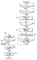
- FIG. 6 shows an example of a control flow of the surgical treatment instrument 12 by the high-frequency energy output unit 104.
- the fluid reservoir 122 of the fluid source 18 after joining the living tissues L1, L2 between the treatment with high-frequency energy, putting fluid for coating the outer periphery of the joining living tissue L T the two living tissues L1, L2 Keep it.
- the fluid is described as a bonding agent for living tissue L T.
- this adhesive dries when touched with air or the like, and particularly has a quick drying property.
- the hose 18a connected to the fluid reservoir 122 is closed by the flow rate adjusting mechanism 134 so that the adhesive normally does not flow from the fluid reservoir 122 toward the energy treatment device 12.
- the surgeon operates the display unit 108 of the energy source 14 in advance to set the output condition of the treatment system 10 (Step S11).
- the display unit 108 checks the output from the high frequency energy output unit 104 (set power Pset [W]), the threshold value Z1 [ ⁇ ] of the impedance Z by the detection unit 106, the maximum energy supply time t1 [sec], and the like.
- the output from the high-frequency energy output unit 104 and the threshold value Z1 of the impedance Z by the detection unit 106 are set to different values, such setting is made and the display unit 108 confirms it.
- the flow rate V1 which flows from the fluid storage part 122 to the energy treatment tool 12 through the hose 18a is set.
- the longest time t-max for keeping the hose 18a open is set. That is, even if the flow rate V1 is not reached after opening the hose 18a, the hose 18a is automatically closed after elapse of time t-max.
- the treatment portion 26 and the shaft 24 of the surgical treatment instrument 12 are inserted into the abdominal cavity through the abdominal wall.
- the treatment portion 26 of the surgical treatment instrument 12 is opposed to the biological tissues L1 and L2 of the treatment target (holding target).
- the treatment section opening / closing knob 32 of the handle 22 is operated.
- the sheath 44 is moved to the proximal end side of the shaft 24 with respect to the cylindrical body 42. Due to the urging force of the elastic member 84, the base portions 64 and 74 cannot be maintained in a cylindrical shape, and the second holding member 54 opens with respect to the first holding member 52.
- the living tissues L1 and L2 having a symmetrical connection are arranged between the high frequency electrodes 92 and 94 of the first and second holding members 52 and 54.
- the treatment section opening / closing knob 32 of the handle 22 is operated.
- the sheath 44 is moved toward the distal end side of the shaft 24 with respect to the cylindrical body 42.
- the sheath 44 is closed against the urging force of the elastic member 84 so that the base portions 64 and 74 are closed to form a cylinder. Therefore, the main body 62 of the first holding member 52 formed integrally with the base portion 64 and the main body 72 of the second holding member 54 formed integrally with the base portion 74 are closed. That is, the second holding member 54 is closed with respect to the first holding member 52. In this way, the living tissues L1 and L2 to be joined are held between the first holding member 52 and the second holding member 54.
- the treatment target living tissue L1 is in contact with the high frequency electrode 92 of the first holding member 52, and the treatment target living tissue L2 is in contact with the high frequency electrode 94 of the second holding member 54.
- the surrounding tissues of L1 and L2 are in close contact. Note that the contact surface C1 of the living tissue L1 is in contact with the contact surface C2 of the living tissue L2 so as to apply pressure to each other.
- the pedal of the foot switch 16 is operated in a state where the living tissues L1 and L2 are held between the first holding member 52 and the second holding member 54.
- a signal is input from the foot switch 16 to the first control unit 102, and the first control unit 102 of the energy source 14 determines whether or not the pedal of the switch 16 is pressed and turned on by an operator's operation. (S12).
- the first control unit 102 determines that the pedal of the switch 16 is pressed and switched to ON, a signal is input from the first control unit 102 to the high-frequency energy output unit 104.
- the high-frequency energy output unit 104 generates energy and supplies the energy to the living tissues L1 and L2 between the high-frequency electrodes 92 and 94 through the energization lines 28a and 28b (S13). At this time, the high-frequency energy output unit 104 has a preset power Pset [W] set in advance by the display unit 108 between the high-frequency electrode 92 of the first holding member 52 and the high-frequency electrode 94 of the second holding member 54, for example, Power of about 20 [W] to 80 [W] is supplied.
- the high frequency energy output unit 104 supplies a high frequency current to the living tissues L1 and L2 to be joined between the high frequency electrode 92 of the first holding member 52 and the high frequency electrode 94 of the second holding member 54. That is, high-frequency energy is applied to the living tissues L1 and L2 held between the high-frequency electrodes 92 and 94. For this reason, Joule heat is generated in the living tissues L1 and L2 held between the high-frequency electrodes 92 and 94, and the living tissues L1 and L2 themselves are heated.
- the cell membranes in the living tissues L1 and L2 held between the high-frequency electrodes 92 and 94 are destroyed to release substances in the cell membrane, and homogenize with extracellular components such as collagen. Since high-frequency current is applied to the living tissues L1 and L2 between the high-frequency electrodes 92 and 94, further Joule heat is applied to the tissues L1 and L2 thus homogenized, for example, the living tissues L1 and L2.
- the contact surfaces C1 and C2 and the tissue layers are joined to each other.
- the living tissues L1 and L2 themselves generate heat and dehydrate while the inside of the living tissues L1 and L2 is denatured (the living tissues L1 and L2).
- L2 is cauterized), and the contact surfaces C1 and C2 are brought into close contact with each other to form a joint C.
- two living tissues L1, L2 with each other are joined, the living tissue L T having a joint portion C is formed.
- the holding surfaces 62a and 72a of the main bodies 62 and 72 of the first and second holding members 52 and 54 have a higher degree of adhesion to the living tissues L1 and L2 than the high-frequency electrodes 92 and 94.
- the holding surfaces 62a and 72a function as barrier portions (dams) that prevent the fluid from the living tissues L1 and L2 from escaping to the outside of the first holding member 52 and the second holding member 54. That is, it is possible to prevent thermal spread from occurring in living tissues other than the living tissues L1 and L2 to be joined.
- the initial value Z0 of the impedance Z when the treatment is started is, for example, about 50 [ ⁇ ] to 60 [ ⁇ ]. .
- the impedance Z once decreases to Zmin (for example, about 10 [ ⁇ ]) and then gradually increases.
- the first control unit 102 controls the detection unit 106 so as to calculate information on the living tissues L1 and L2 between the high-frequency electrodes 92 and 94 at equal time intervals (for example, several milliseconds).
- the first control unit 102 has a threshold Z1 (in this case, as shown in FIG. 5A), in which the impedance Z at the time of high-frequency energy output calculated based on the signal from the detection unit 106 is preset (S11) on the display unit 108. 1000 [ ⁇ ]) or more is determined (S14).
- the threshold value Z1 of the impedance Z can be set appropriately.
- the threshold value Z1 is preferably larger than the initial value Z0, for example, and is at a position where the rate of increase in the value of impedance Z slows (see FIG. 5A).
- a signal is transmitted from the first control unit 102 to the high-frequency energy output unit 104.
- output from the high-frequency energy output unit 104 to the high-frequency electrodes 92 and 94 of the first and second holding members 52 and 54 is stopped (S151).
- the energy output is continued.
- the living tissues L1 and L2 held between the high-frequency electrodes 92 and 94 of the first and second holding members 52 and 54 are determined.
- the energy output from the high-frequency energy output unit 104 Stop.
- the living tissue L T is joined at a junction C.
- the pedal of the foot switch 16 is kept pressed. It also maintains the state of being held by the holding members 52, 54 the living tissue L T.
- the first control unit 102 At the same time as the supply of energy from the high-frequency energy output unit 104 to the high-frequency electrodes 92 and 94 is stopped by the first control unit 102 (S151), a signal is transmitted from the first control unit 102 to the second control unit 132. Is done.
- the second control unit 132 operates the flow rate adjustment mechanism 134 to open the hose 18a (S152). For this reason, the adhesive is supplied from the fluid reservoir 122 to the energy treatment device 12 through the hose 18a.
- the pipes 64 a and 74 a of the base portions 64 and 74 of the first and second holding members 52 and 54 and the flow passage 62 b of the main bodies 62 and 72 are passed from the fluid storage portion 122 through the inside of the handle 22 and the shaft 24 by the hose 18 a. , 72b is supplied with an adhesive. For this reason, the adhesive oozes out from the openings 92a, 94a of the high-frequency electrodes 92, 94 formed along the flow paths 62b, 72b of the main bodies 62, 72.
- the adhesive that has oozed out from the openings 92a and 94a of the high-frequency electrodes 92 and 94 is spread and applied so as to coat the outer peripheral surface of the joined living tissue. That is, the adhesive is applied to the entire surface where the high-frequency electrodes 92 and 94 are in contact with the living tissue. Then, for example, when the adhesive is exposed to air, it gradually hardens with the passage of time.
- the adhesive here preferably has quick-drying properties, and has waterproof properties when cured. Therefore, the outer surface Sc of the living tissue L T joined by adhesive cures are coated. This can prevent a from the outer surface Sc of joining living tissue L T (between the contact surfaces C1, C2) junction C to liquid intrusion.
- the nature of the adhesive varies depending on the type of adhesive, but the adhesive in this embodiment is applied after bonding of the living tissues L1 and L2 because the adhesive for living tissues is an effective bond. This is because the living tissues L1 and L2 are applied as dry as possible. That is, if the adhesive is applied without sufficiently removing moisture, it becomes difficult to remove moisture from the living tissues L1 and L2 even by energy administration, but by applying the adhesive after joining the living tissues L1 and L2, Such a state can be prevented. In addition, if the adhesive is applied without sufficiently removing moisture, moisture may be mixed with the adhesive, but this condition is prevented by applying the adhesive after joining the living tissues L1 and L2. can do.
- the second control unit 132 operates the flow rate adjusting mechanism 134 again when the adhesive having a predetermined flow rate is passed from the fluid storage unit 122 through the hose 18a (S16) or after the hose 18a is opened for a predetermined time.
- the hose 18a is closed (S17).
- a sound such as a buzzer is emitted from the speaker 110 to prevent the invasion of water into the bonded contact surfaces C1 and C2. (S18) that the treatment to be completed) has been completed. Then, after recognizing that the treatment is completed by the sound from the speaker 110 or the display on the display unit 108, the doctor or the like releases the pedal by releasing the foot of the foot switch 16.
- the treatment is performed from the “start” to the “end” shown in FIG. 6 while the pedal of the foot switch 16 is being pressed.
- the first controller 102 forcibly stops the treatment when the pedal is released. That is, when the supply of high-frequency energy is stopped halfway or the supply of adhesive is stopped halfway, the foot of the foot switch 16 is released before the buzzer or the like is emitted from the speaker 110, and the pedal is pressed. Is released.
- the first controller 102 stops the output from the high-frequency energy output unit 104 to the electrodes 92 and 94 when energy is output from the high-frequency energy output unit 104.
- the second control unit 132 operates the flow rate adjustment mechanism 134 to close the hose 18a and stop the supply of fluid.
- the physician operates the treatment portion opening and closing knob 32 Recognizing the buzzer sound from the speaker 110, to release the living tissue L T.
- the contact surfaces C1 and C2 between the living tissues are joined to form a joined portion C.
- the living tissue L T the adhesive having a bioabsorbable is, since gradually hardened with shaking towards the junction C from the outer surface Sc, the living tissue L T is coated with an adhesive It becomes.
- the adhesive since the adhesive has bioabsorbability, the adhesive that oozes out from the openings 92a and 94a may be applied to the side surfaces of the biological tissues L1 and L2 shown in FIG. 5B.
- the fluid adjusting unit 124 may control the flow rate of the adhesive to the living tissue using a rotary pump or the like.
- the following effects can be obtained.
- the contact surfaces C1 and C2 between the living tissues L1 and L2 can be more reliably adhered.
- the bonding treatment of the living tissue L1, L2 together by coating the outer periphery of the living tissue L T joined treated with an adhesive or the like, the water at the junction C of the living tissue L T junction treatment intrusion Can be prevented. Therefore, it is possible to contact surfaces C1, C2 of the body tissue L1, L2 maintains long coherent state (the living tissue L T is bonded).
- the outer periphery of the joining living tissue L T as the fluid material to be coated brought into juxtaposed two types of liquids to the fluid source 18 It ’s fine.
- the two hoses 18 a are extended from the fluid source 18 to the energy treatment instrument 12, and the main bodies of the first and second holding members 52 and 54 of the treatment portion 26 are passed through the handle 22 and the shaft 24.
- the liquid is supplied independently to the flow paths 62b and 72b of 62 and 72, respectively. And what is necessary is just to make it mix when two types of liquid oozes out from opening 92a, 94a of the high frequency electrodes 92,94.
- the detection unit 106 includes a voltage detection unit 142, a current detection unit 144, and a phase detection unit 146, as shown in FIG.
- the phase detection unit 146 is connected to the first control unit 102.
- the voltage detection unit 142 and the current detection unit 144 are connected to the energy treatment device 12 (high-frequency electrodes 92 and 94) and to the phase detection unit 146.
- the energy treatment device 12 high-frequency electrodes 92 and 94
- a high frequency current having a predetermined frequency and peak value based on the high frequency voltage of the high frequency energy output unit 104 is supplied to the surgical treatment instrument 12 via the current detection unit 144. Is output.
- the voltage detection unit 142 detects the peak value of the high-frequency voltage that has passed through the high-frequency energy output unit 104, and outputs the detected peak value to the phase detection unit 146 as output voltage value information.
- the current detection unit 144 detects a peak value of the high-frequency current generated based on the high-frequency voltage passed through the high-frequency energy output unit 104, and outputs the detected peak value to the phase detection unit 146 as output current value information. .
- the phase detection unit 146 detects the phase of the high frequency voltage output through the high frequency energy output unit 104 based on the output voltage value information output from the voltage detection unit 142, and then outputs the detected phase as output voltage phase information.
- the voltage value information is output to the first control unit 102.
- the phase detection unit 146 detects the phase of the high-frequency current that has passed through the high-frequency energy output unit 104 based on the output current value information output from the current detection unit 144, and then uses the detected phase as output current phase information. Output to the first control unit 102 together with the output current value information.
- the first control unit 102 outputs the output voltage value information output from the phase detection unit 146, the output voltage phase information, the output current value information, and the output current phase information through the high frequency energy output unit 104.
- the phase difference ⁇ between the high frequency voltage and the high frequency current to be calculated is calculated.
- the first control unit 102 outputs a high-frequency current and a high-frequency voltage to the high-frequency energy output unit 104 based on the instruction signal output according to the pedal operation of the foot switch 16 and the calculated phase difference ⁇ . Control to change the state to ON state or OFF state is performed.
- the phase difference ⁇ of the high-frequency current and the high-frequency voltage output through the high-frequency energy output section 104, in the initial stage of performing treatment on the living tissue L T is 0 ° or substantially 0 °.
- the value of the phase difference ⁇ is set to 90 ° or a value close thereto.
- the treatment of the living tissues L1 and L2 held between the high-frequency electrodes 92 and 94 of the first and second holding members 52 and 54 proceeds, dehydration from the living tissues L1 and L2 occurs.
- the living tissues L1 and L2 are cauterized or solidified.
- the phase difference ⁇ between the high-frequency voltage and the high-frequency current output through the high-frequency energy output unit 104 increases from a state of 0 ° or substantially 0 °, for example, at an appropriate time t1.
- the value of the phase difference ⁇ calculated by the first control unit 102 is It takes a constant value near 90 ° shown in FIG.
- the first control unit 102 is not limited to performing the above-described control when detecting that the phase difference ⁇ has become a constant value in the vicinity of 90 °.
- the phase difference ⁇ The above-described control may be performed when it is detected that is constant at a predetermined value greater than 45 ° and 90 ° or less.
- the display unit 108 appropriately set and use the change of the impedance Z and the change of the phase ⁇ , such as the one that reaches the threshold earlier or the later.
- treatment with thermal energy using a heater (illustration is omitted because it is the same as the high frequency electrodes 92 and 94 in the drawing) instead of the high frequency electrodes 92 and 94 can be performed.
- the treatment is advanced while measuring the temperature of the living tissue in contact with the heater.
- a monopolar type treatment device (see FIG. 9) may be used.
- a counter electrode 150 is attached to the patient P to be treated.
- the counter electrode plate 150 is connected to the energy source 14 through an energization line 150a.
- the high-frequency electrode 92 disposed on the first holding member 52 and the high-frequency electrode 94 disposed on the second holding member 54 have the same potential to which the energization lines 28a and 28b are electrically connected. Is in a state.
- the current density is increased. Lower.
- the living tissues L1 and L2 held by the first and second holding members 52 and 54 are heated by Joule heat, whereas the heating of the living tissues in contact with the counter electrode plate 150 is negligible. small. Therefore, only the living tissues L1 and L2 that are in contact with the high-frequency electrodes 92 and 94 having the same potential are heated and denatured in the portions gripped by the first and second holding members 52 and 54.
- the case where the living tissues L1 and L2 are treated using high-frequency energy has been described.
- energy such as microwaves may be used.
- the high frequency electrodes 92 and 94 can be used as microwave electrodes.
- the linear type energy treatment tool 12 (see FIG. 1) for treating living tissues L1 and L2 in the abdominal cavity (in the body) through the abdominal wall has been described as an example.
- an open linear type energy treatment tool (treatment tool) 12a for taking a treatment target tissue out of the body through the abdominal wall and performing a treatment can also be used.
- the energy treatment instrument 12a includes a handle 22 and a treatment portion (holding portion) 26. That is, unlike the energy treatment device 12 (see FIG. 1) for treating through the abdominal wall, the shaft 24 is removed. On the other hand, a member having the same action as that of the shaft 24 is disposed in the handle 22. For this reason, the energy treatment tool 12a shown in FIG. 10 can be used similarly to the energy treatment tool 12 shown in FIG. 1 described above.
- a fluid conduit 162 having an insulating property is disposed instead of the flow path (recess) 62b (see FIGS. 4A to 4C).
- the openings 92a and 94a of the high-frequency electrodes 92 and 94 described in the first embodiment are removed.
- the fluid conduit 162 is annularly disposed at a position close to the surface of the high-frequency electrode 92 along the outer peripheral edge of the main body 62. As shown in FIG. 11C, the cross section of the fluid conduit 162 is formed in, for example, a circular shape or a rectangular shape.
- the fluid conduit 162 preferably has an appropriate elastic force so as to be in close contact with the outer surface of the living tissue L1 when the living tissues L1 and L2 are held by the first and second holding members 52 and 54.
- the fluid conduit 162 is connected to the conduit 64 a of the base 64 of the first holding member 52.
- a high frequency electrode 92 is disposed inside the fluid conduit 162.
- the fluid conduit 162 is formed with a plurality of openings (joining maintenance auxiliary part, discharge part) 162a at appropriate intervals. These openings 162a are directed to the surface of the high-frequency electrode 92 and to the central axis of the high-frequency electrode 92, as shown in FIGS. 11B and 11C. For this reason, the fluid discharged from the opening 162 a of the fluid conduit 162 can flow toward the central axis of the high-frequency electrode 92 along the surface of the high-frequency electrode 92.
- the fluid conduit 162 serves as a barrier that prevents fluid such as vapor generated from the living tissues L1 and L2 from leaking to the outside when the living tissues L1 and L2 are treated using the high-frequency electrode 92. Fulfill.
- a fluid conduit 164 having an opening (joining maintenance auxiliary portion) 164a is also provided at the edge of the main body 72 of the second holding member 54, symmetrically with the first holding member 52. Yes. For this reason, the fluid conduit 164 serves as a barrier that prevents the fluid such as vapor generated from the living tissues L1 and L2 from leaking outside when the living tissues L1 and L2 are treated using the high-frequency electrode 94. Fulfill.
- the fluid conduit 164 is connected to the conduit 74 a of the base 74 of the second holding member 54.
- the fluid conduit 162 is formed as a double lumen, one (inner side) is a pipe line having an opening 162a, and the other (outer side) is a pipe line through which gas or liquid is passed as a refrigerant. preferable.
- the portions of the living tissues L1 and L2 in contact with the fluid conduit 162 can be cooled. For this reason, heat is prevented from being transferred through the living tissues L1 and L2 to the outside of the holding surfaces 62a and 72a of the first and second holding members 52 and 54, and the outside of the living tissues L1 and L2 to be treated is prevented. The influence of heat on the living tissues L1 and L2 can be prevented more reliably.
- the handle 22 of the energy treatment device 12 b includes a cutter drive knob 34 for moving a cutter (treatment auxiliary tool) 180, which will be described later, in a state of being arranged in parallel with the treatment section opening / closing knob 32. ing.
- the second detection unit 107 includes a first control for the energy source 14. Connected to the unit 102.
- the second detection unit 107 is connected to a sensor 185 disposed in locking portions 184a, 184b, and 184c of a long groove 184 described later of the cutter 180.
- the outer shapes of the main bodies 62 and 72 and the bases 64 and 74 of the first and second holding members 52 and 54 are the same as those of the second embodiment except that cutter guide grooves 172 and 174 described later are formed.
- the second holding members 52 and 54 are formed in the same manner.
- a straight cutter guide groove 172 is formed on the side of the main body 62 and the base 64 of the first holding member 52 that is close to the second holding member 54.
- a straight cutter guide groove 174 is formed in the main body 72 and the base 74 of the second holding member 54 on the side close to the first holding member 52.
- the cutter guide grooves 172 and 174 are provided with a single cutter 180, which will be described later, so that it can be taken in and out.
- the high-frequency electrodes 92 and 94 disposed on the main bodies 62 and 72 of the first and second holding members 52 and 54 are formed, for example, in a substantially U shape, and the first and second The base members 62 and 72 of the holding members 52 and 54 have two ends at the base ends. That is, the high frequency electrodes 92 and 94 are formed continuously.
- the high-frequency electrodes 92 and 94 are formed with cutter guide grooves (reference numerals 172 and 174 for convenience) for guiding the cutter 180 together with the first and second holding members 52 and 54.
- the cutter guide grooves 172 and 174 of the first and second holding members 52 and 54 are formed so as to face each other, and are formed along the axial direction of the shaft 24.
- One cutter 180 can be guided by the two cutter guide grooves 172 and 174 that the first and second holding members 52 and 54 cooperate with each other.
- the cutter guide groove 172 of the first holding member 52 is formed on the central axis of the main body 62 and the base portion 64 of the first holding member 52, and the cutter guide groove 174 of the second holding member 54 is the second holding member. It is formed on the central axis of the main body 72 and the base 74 of the member 54.
- a driving rod 182 is disposed inside the cylindrical body 42 of the shaft 24 so as to be movable along the axial direction thereof.
- a cutter driving knob 34 is disposed at the proximal end of the driving rod 182.
- a thin plate-like cutter (treatment auxiliary tool) 180 is disposed at the tip of the drive rod 182. Therefore, when the cutter driving knob 34 is operated, the cutter 180 moves along the axial direction of the shaft 24 via the driving rod 182.
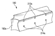
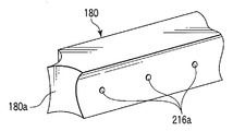
- the cutter 180 has a blade 180a formed at the tip thereof, and the tip of the drive rod 182 is fixed at the base end.
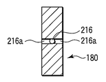
- a long groove 184 is formed between the distal end and the proximal end of the cutter 180.
- a movement restricting pin 42 a extending in a direction orthogonal to the axial direction of the shaft 24 is fixed to the cylindrical body 42 of the shaft 24.
- the long groove 184 of the cutter 180 moves along the movement restricting pin 42a.
- the cutter 180 moves straight.
- the cutter 180 is disposed in the cutter guide grooves (flow paths, fluid discharge grooves) 172 and 174 of the first and second holding members 52 and 54.
- the movement restricting pin 42a is locked at one end and the other end of the long groove 184 of the cutter 180, and between the one end and the other end, for example, and locking portions 184a for controlling the movement of the cutter 180 are provided. 184b and 184c are formed.
- the long groove 184 of the cutter 180 is provided with a sensor 185 capable of recognizing the position of the movement restricting pin 42a and recognizing the moving direction of the movement restricting pin 42a.
- Various sensors 185 such as a sensor using light or a contact type sensor are used.
- the blade 180a of the cutter 180 is housed inside the shaft 24, and the movement restricting pin 42a at the other end (rear end) 184b.
- the second detection unit 107 can recognize the position of the blade 180a of the cutter 180 with respect to the shaft 24 and the treatment unit 26 by the sensor 185, and determines whether or not the biological tissue is cut by the blade 180a of the cutter 180. It can be easily judged.
- Fluid discharge ports 186 and 188 from which fluids such as vapor (gas) and liquid (tissue fluid), which will be described later, are discharged are respectively provided in the cylindrical body 42 and the sheath 44 of the shaft 24 of the energy treatment device 12 shown in FIGS. 15A and 15B. Is formed. These fluid discharge ports 186 and 188 are formed on the proximal end side of the shaft 24. Although not shown here, it is also preferable that a connection cap is provided on the outer peripheral surface of the fluid discharge port 188 of the sheath 44.
- the fluid to be described later is discharged through the cutter guide grooves 172 and 174, the fluid discharge port 186 of the cylindrical body 42 of the shaft 24, the fluid discharge port 188 of the sheath 44 of the shaft 24, and the connection cap.
- the connection cap by sucking the inside of the connection cap, fluid such as vapor and liquid discharged from the living tissues L1 and L2 can be easily discharged from the fluid discharge ports 186 and 188.
- the fluid discharge ports 186 and 188 are preferably provided in the shaft 24, but are preferably provided in the handle 22.
- first fluid conduits 162, 164 (in the second embodiment, simply a fluid conduit 162) are provided in the bodies 62, 72 of the first and second holding members 52, 54. , 164), which has been described in the second embodiment, the description thereof is omitted here.
- second fluid conduits 192 and 194 having insulating properties are disposed at the edges of the cutter guide grooves 172 and 174.
- the second fluid conduit 192 is connected to the pipe line 64 a of the base 64 of the first holding member 52.
- another second fluid conduit 194 is connected to the conduit 74 a of the base 74 of the second holding member 54, for example.
- the second fluid conduits 192 and 194 are formed with a plurality of openings (joining maintenance auxiliary portion and discharge portion) 192a and 194a at appropriate intervals.
- the orientations of the openings 192a and 194a of the fluid conduits 192 and 194 are directed to the same second fluid conduits 192 and 194 facing each other with the cutter 180 therebetween.
- second fluid conduits 192 and 194 may each be a pair, or each fluid conduit 192 and 194 may be bent in a substantially U shape.
- the surgeon operates the display unit 108 of the energy source 14 in advance to set the output condition of the treatment system 10 (S31).
- the display unit 108 checks the output from the high frequency energy output unit 104 (set power Pset [W]), the threshold value Z1 [ ⁇ ] of the impedance Z by the detection unit 106, the energy supply time t1 [sec], and the like.
- the output from the high-frequency energy output unit 104 and the threshold value Z1 of the impedance Z by the detection unit 106 are set to different values, such setting is made and the display unit 108 confirms it.
- the flow rate V1 which flows from the fluid storage part 122 to the energy treatment tool 12 through the hose 18a is set.
- the treatment portion 26 and the shaft 24 of the surgical treatment instrument 12 are inserted into the abdominal cavity through the abdominal wall.
- the treatment portion opening / closing knob 32 of the handle 22 is operated, and the biological tissues L1 and L2 to be joined are first and first.
- the two holding members 52 and 54 are held.
- the pedal of the foot switch 16 is operated in a state where the living tissues L1 and L2 are held between the first holding member 52 and the second holding member 54.
- a signal is input from the foot switch 16 to the first control unit 102, and the first control unit 102 of the energy source 14 determines whether or not the pedal of the switch 16 has been pressed and turned ON by an operator's operation ( S32).
- the first control unit 102 determines that the pedal of the switch 16 is pressed and switched to ON, a signal is input from the first control unit 102 to the high-frequency energy output unit 104.
- the high frequency energy output unit 104 supplies energy to the living tissues L1 and L2 between the high frequency electrodes 92 and 94 through the energization lines 28a and 28b (S33). Then, a high-frequency current is passed through the living tissues L1 and L2 between the high-frequency electrodes 92 and 94.
- the living tissues L1 and L2 themselves generate heat and are dehydrated, the inside of the living tissues L1 and L2 is denatured (the living tissues L1 and L2 are cauterized), and the contact surfaces C1 and C2 between the living tissues L1 and L2 are joined. Part C. It is determined whether or not the impedance Z has reached a predetermined threshold value Z1 (S34). When the impedance Z has reached the threshold value Z1, the supply of high-frequency energy is stopped (S35).
- a buzzer sound (first buzzer sound) for notifying the end of the joining treatment of the living tissues L1 and L2 using high frequency energy is emitted from the speaker 110 (S36).
- the doctor operates the cutter driving knob 34 shown in FIG. That is, the cutter 180 is advanced along the cutter guide grooves 172 and 174 from the state shown in FIGS. 15A and 15B. As the cutter 180 moves forward, the portions that have been modified and joined by the high-frequency electrodes 92 and 94 are cut. At this time, the sensor 185 detects, for example, the relative positions of the locking portions 184a, 184b, and 184c with respect to the movement restricting pin 42a, and transmits them to the second detection unit 107. The second detection unit 107 recognizes the position and moving direction of the cutter 180 with respect to the shaft 24 and the treatment unit 26 (S37).
- the direction of movement of the cutter 180 detected by the second detection unit 107 when it is recognized to be moving in a direction of cutting the living tissue L T, the first control unit 102 signals to the second control unit 132 Then, the flow rate adjusting mechanism 134 is operated to open the hose 18a (S38).
- the adhesive passes through the hose 18a, and the adhesive oozes out from the openings 162a and 164a of the fluid conduits 162 and 164 of the first and second holding members 52 and 54, and the openings of the fluid conduits 192 and 194 The adhesive oozes out from 192a and 194a. Then, the opening 162a of the fluid conduit 162, with the adhesive oozed from 164a is applied to the portion in contact with the high-frequency electrode 92, 94 (the outer peripheral surface Sc of the joint living tissue L T), the fluid conduit 192, Adhesive that oozes out from the openings 192 a and 194 a of 194 is applied to the side surface of the cutter 180. Therefore, the adhesive on the cut surface S of the living tissue L T by the cutter 180 by the side surface of the cutter 180 contacts the cut surface S of the living tissue L T upon cleavage of the living tissue L T is applied.
- a buzzer sound (second buzzer sound) for notifying that the application of the adhesive is finished is emitted from the speaker 110 (S311).
- Physician as well as releasing the pressure of the pedal of the foot switch 16
- the treatment portion opening and closing knob 32 of the handle 22 operates the treatment portion opening and closing knob 32 of the handle 22, to release the living tissue L T.
- the living tissues L ⁇ b> 1 and L ⁇ b> 2 are joined at the joint C and cut along the cut surface S.
- the surface Sc and the cut surface S of the joint C are coated with an adhesive.
- Fluid such as blood generated from the living tissues L1 and L2 during the treatment can be put into the cutter guide grooves 172 and 174. Then, the fluid placed in the cutter guide grooves 172 and 174 can be guided to the outside of the energy treatment device 12b from the fluid discharge ports 186 and 188 formed in the cylindrical body 42 and the sheath 44 of the shaft 24. For this reason, it is possible to prevent moisture from remaining on the joint surfaces of the joint portions C of the living tissues L1 and L2 as much as possible, and the joining treatment of the living tissues L1 and L2 can be performed more quickly. Therefore, a series of treatments for joining the living tissues L1 and L2 and coating the joined portion C can be performed more efficiently.
- the outer peripheral surface of the living tissue L T to be joined as well as coated with an adhesive since the cut surface S of the living tissue L T can be coated bonding surface by applying an adhesive, a biological tissue the penetration of moisture into the joint C of the L T can be prevented.
- the hose 18a may be opened to allow the adhesive to flow, but the movement restricting pin 42a of the cylindrical body 42 is intermediate from the one end 184a of the long groove 184 of the cutter 180.
- the hose 18a may be opened after reaching the other end 184b through the portion 184c.
- cleavage of the living tissue L T by the blade 180a of the cutter 180 (already cut surface S is formed) already completed at that.
- the adhesive is allowed to flow until the movement regulating pin 42a of the cylindrical body 42 reaches the one end 184a through the intermediate portion 184c from the other end 184b of the long groove 184 of the cutter 180.
- the blade 180a of the cutter 180 the space is formed by the cut surface S between the living tissue L T as it is drawn into the shaft 24 from the cutter guide groove 172, 174 of the first and second holding members 52, 54.
- the adhesive oozes out from the openings 192a and 194a, the adhesive enters between the cut surfaces S.
- the movement restricting pin 42a of the cylindrical member 42 is moved between one end 184a and the other end 184b of the long groove 184 of the cutter 180 can be detected by the sensor 185, and the living tissue L T to be joined
- the positional relationship with the cutter 180 can be easily grasped. For this reason, the timing at which the hose 18a is closed by the flow rate adjusting mechanism 134 can also be set appropriately.
- the buzzer sound is emitted from the speaker 110.
- the content of the treatment may be notified by voice, or the procedure of the treatment may be notified by voice.
- the first buzzer sound and the second buzzer sound are greatly different, and it is preferable that it is possible to easily recognize what kind of treatment has been completed.
- the cutter 180 is manually operated by operating the cutter driving knob 34 .
- the cutter driving knob 34 is operated. it is also preferable that the automatically operating the cutter 180 without operating so as to cut the living tissue L T. That is, from the start of treatment using the high-frequency energy for joining living tissues L1, L2 together, so as to automatically perform a series of treatments of the bonding living tissue L T to the end of the treatment for coating Also good.
- FIGS. 18A to 20 a fourth embodiment will be described with reference to FIGS. 18A to 20.
- This embodiment is a modification of the first embodiment, and the same members as those described in the first embodiment or the members having the same functions are denoted by the same reference numerals and are described in detail. Is omitted.
- the main body 62 of the first holding member 52 has a recess 62 b.
- a first high frequency electrode 92 is disposed on the main body 62 of the first holding member 52.
- a plurality of protrusions (bonding maintenance assisting portions) 202 are formed on the recess 62 b of the main body 62 of the first holding member 52 toward the second holding member 54.
- the protrusion 202 is formed in an appropriate length so as to form the hole P shown in FIG. 20 in the living tissues L1 and L2.
- each protrusion 202 does not necessarily pass through the living tissues L1 and L2, and the tip of the protrusion 202 (distal end portion with respect to the first high-frequency electrode 92) is more than the contact surfaces C1 and C2 of the living tissues L1 and L2. It is preferable to be in a position close to the second high-frequency electrode 94. As shown in FIG. 18D, each protrusion 202 is formed with one or a plurality of openings (bonding maintenance assisting part, discharge part) 204. Note that a plurality of openings 204 are preferable.
- the protrusion 202 communicates with the recess 62b, and fluid such as an adhesive (joining aid) can be oozed out through the recess 62b.
- the main body 72 and the high-frequency electrode 94 of the second holding member 54 are formed with a concave portion (joining maintenance auxiliary portion) 206.
- Each recess 206 is formed so as to receive the projection 202 protruding from the high-frequency electrode 92 disposed on the first holding member 52.
- the surfaces of the high-frequency electrodes 92 and 94 are positioned lower than the edges 62a and 72a of the main bodies 62 and 72 of the first and second holding members 52 and 54. Further, the length of the protrusion 202 of the first high-frequency electrode 92 is formed so as not to contact the concave portion 206 of the second holding member 54. Therefore, even when the protrusion 202 of the first high-frequency electrode 92 is disposed in the recess 206 of the second high-frequency electrode 94, the first high-frequency electrode 92 and the second high-frequency electrode 94 are formed so as not to contact each other. ing.
- the living tissues L1 and L2 to be joined are held.
- the projection 202 since the projection 202 is disposed on the high-frequency electrode 92 disposed on the first holding member 52, the projection 202 penetrates the living tissues L1 and L2 to form the hole P, and the second The holding member 54 and the recess 206 disposed in the high-frequency electrode 94 are received.
- the two living tissues L1 and L2 are joined by the high-frequency energy output from the high-frequency electrodes 92 and 94 disposed on the first and second holding members 52 and 54.
- the protrusion 202 provided on the high-frequency electrode 92 provided on the first holding member 52 maintains a state of being penetrated through the living tissues L1 and L2 (a state provided in the hole P).
- the protrusion 202 is disposed inside the living tissues L1 and L2, and the living tissue between the protrusion 202 and the second high-frequency electrode 94 is energized, the high-frequency energy of the living tissues L1 and L2 is used. Treatment can be performed efficiently.
- the flow rate adjusting mechanism 134 is opened, and the adhesive is allowed to flow from the fluid reservoir 122 through the hose 18a.
- the pipe 64 a is provided in the base 64 of the first holding member 52 and the recess 62 b is provided in the main body 62, the adhesive oozes out from the opening 204 of the protrusion 202.
- the protrusion 202 is disposed in the penetrating a hole P of the living tissue L T junction, adhesive oozed from the opening 204 is applied partially to the joint C between the living tissue L T Is done. Part of the adhesive penetrates directly from the joint surface of the joint C. Since the adhesive has a coating action in addition to the adhesion action, it is possible to prevent moisture from entering the joining portion C and maintain the joined state.
- Joule heat can be generated not only between the high-frequency electrodes 92 and 94 but also in the living tissues L1 and L2 between the projections 202 penetrating the living tissues L1 and L2 and the high-frequency electrodes 94, so that the living tissues L1 and L2 Is thick (when high-frequency energy is difficult to penetrate the living tissues L1 and L2), the energy can be easily penetrated into the living tissues L1 and L2.
- the joint C and the like of the living body tissue L1, L2 to be joined since the fluid such as an internal direct adhesive bonding living tissue L T can be infiltrated by supplying
- the bonding of the bonding portion C can be made more reliable, and the coating action of the adhesive can be exerted in the vicinity of the bonding portion C including the bonding surface.
- the holes P are formed in the living tissues L1, L2 by the projections 202 of the first holding member 52.
- the protrusion 202 does not necessarily need to be formed with the hole P when the living tissues L1 and L2 are held by the first and second holding members 52 and 54. That is, when the living tissues L1 and L2 are held by the first and second holding members 52 and 54, the protrusion 202 of the first holding member 52 presses the living tissue L2 against the recess 206 of the second holding member 54. You may do it.
- the holes P are formed in the living tissues L1 and L2 as the high frequency energy is supplied to the living tissues L1 and L2 between the first and second high frequency electrodes 92 and 94, that is, the protrusions 202 are formed in the holes. It is arranged in P.
- the projection 202 of the high-frequency electrode 92 of the first holding member 52 may be formed of a separate body such as an insulating hard resin material. In this case, the protrusion 202 is allowed to contact the high frequency electrode 94 of the second holding member 54.
- FIGS. 21A to 23 a fifth embodiment will be described with reference to FIGS. 21A to 23.
- This embodiment is a modification of the third embodiment, and the same members as those described in the third embodiment or the members having the same actions are denoted by the same reference numerals and are described in detail. Is omitted.
- FIGS. 21A and 21B in this embodiment, the main bodies 62, 72 of the first and second holding members 52, 54 to the recesses 62b, 72b (see FIGS. 4A to 4C) and the pipes 64a, 74a (see FIGS. 4A to 4C) has been removed.
- the cutter 180 shown in FIG. 22A has a blade 180a at the tip.
- pipes 212 and 214 are formed vertically along the longitudinal direction of the cutter 180 in FIG. 22B.
- Pipe lines 212 and 214 formed inside the cutter 180 are connected to the hose 18 a through the inside of the drive rod 182.
- a plurality of openings (joining maintenance auxiliary portions, discharge portions) 212a and 214a are formed on the side surface of the cutter 180 at appropriate intervals along the longitudinal direction of the cutter 180. Yes.
- These openings 212 a and 214 a communicate with the pipe lines 212 and 214. Therefore, it is possible to produce an opening 212a via line 212, 214, adhesive or the like from 214a, material moisture to the living tissue L T is prevented from penetrating the (auxiliary bonding agent).
- the contact surfaces C1 and C2 of the living tissues L1 and L2 are joined by the high frequency energy emitted from the high frequency electrodes 92 and 94 (S51 to S56).
- the cutter 180 is operated to cut the joining living tissue L T (S57).
- the hose 18a is opened (S58). Therefore, when you are cutting the joined body tissue L T, by ooze the adhesive from the opening 212a of the cutter 180 is applied to the cut surface S. That is, the adhesive was ooze from the opening 212a of the cutter 180 as advancing the cutting of the living tissue L T gradually applied.
- the openings 212a are formed above and below the cutter 180, if it is assumed that the thicknesses of the living tissues L1 and L2 are the same, they are displaced from the joint surface of the joint C. Apply adhesive to the desired location. Since the applied adhesive flows in an appropriate direction depending on the directions of the first and second holding members 52 and 54, the adhesive is applied to the entire cutting surface S by the cutter 180.
- FIGS. 24A to 24D a sixth embodiment will be described with reference to FIGS. 24A to 24D.
- This embodiment is a modification of the fifth embodiment, and the same members as those described in the fifth embodiment or the members having the same functions are denoted by the same reference numerals and are described in detail. Is omitted.
- one pipe line 216 is formed inside the cutter 180 along the longitudinal direction of the cutter 180.
- a pipe line 216 formed inside the cutter 180 is connected to the hose 18 a through the inside of the drive rod 182.
- a plurality of openings (joining maintenance auxiliary portion, discharge portion) 216a are formed. Therefore, at the same time the adhesive and to cut the living tissue L T is applied in the vicinity of the joint surface of the joint C. Accordingly, the adhesive (joining aid) penetrates into the joint surface of the joint C and is cured. In this case, as shown in FIG. 24D, the closer to the cut surface S, the more adhesive penetrates, and the farther from the cut surface S, the smaller the amount of adhesive penetrated.
- FIGS. 25A to 29 a seventh embodiment will be described with reference to FIGS. 25A to 29.
- This embodiment is a modification of the first to sixth embodiments, and the same reference numerals are used for the same members as those described in the first to sixth embodiments or the members having the same functions. The detailed description is omitted.
- the base portion 64 of the first holding member 52 is pivotally supported by a support pin 83 so as to be rotatable with respect to the cylindrical body 42.
- the support pin 83 is disposed in parallel with the support pin 82 described in the first embodiment.
- the base 64 of the first holding member 52 is biased by an elastic member 85 such as a leaf spring, similarly to the elastic member 84 of the base 74 of the second holding member 54.
- the treatment portion 26 of the energy treatment device 12 c has both the first holding member 52 and the second holding member 54 as the central axis of the shaft 24. It is preferable to open symmetrically.
- a pipe-like member (joining maintenance auxiliary portion) 272 is used as a treatment auxiliary tool. Is arranged. The base end of the pipe-shaped member 272 is connected to the hose 18a as shown in FIGS. 27A and 27B.
- a plurality of side holes 272a are formed on the distal end side of the pipe-shaped member 272.
- the pipe-like member 272 can be moved back and forth between the inside of the shaft 24 and the inside of the treatment portion 26 by operating the pipe-like member moving knob 36 disposed on the handle 22. The position of the pipe-shaped member 272 can be detected.
- the main body 62 of the first holding member 52 is formed with a recess (pipe-shaped member guide groove) 62c that forms a space for moving the pipe-shaped member 272 back and forth.
- the width of the recess 62 c is preferably formed slightly larger than the outer diameter of the pipe-like member 272.
- a high-frequency electrode 92b is also disposed in the recess 62c. The high-frequency electrode 92b disposed in the recess 62c and the high-frequency electrode 92 disposed inside the holding surface 62a of the main body 62 have the same potential.
- the main body 72 of the second holding member 54 is also formed with a recess 72c, and a high-frequency electrode 94a having the same potential as the high-frequency electrode 94 is disposed in the recess 72c.
- a channel 62 b, a pipe 64 a and an opening 92 a are formed in the main body 62 of the first holding member 52, and a channel 72 b is formed in the main body 72 of the second holding member 54. It is assumed that a pipe line 74a and an opening 94a are formed. There are at least two hoses 18a, one connected to the pipe-like member 272, and the remaining connected to the flow paths 62b and 72b. For this reason, the timing at which the adhesive flows out from the opening 272a of the pipe-shaped member 272 and the timing at which the adhesive flows out from the openings 92a, 94a of the flow paths 62b, 72b can be shifted simultaneously or shifted.
- the pipe-shaped member 272 of the energy treatment tool 12c is disposed between the living tissues L1 and L2 to be joined.
- the body tissues L1 and L2 are held by the main bodies 62 and 72 of the first and second holding members 52 and 54, and the pipe-like member 272 is held between the body tissues L1 and L2.
- the pipe-like member 272 from the fluid reservoir 122 through the hose 18a, such as an adhesive, introducing substances (auxiliary bonding agent) moisture to the living tissue L T is prevented from penetration. Therefore, material moisture to the living tissue L T from the side hole 272a of the pipe-shaped member 272 to the living tissue L1, L2 to prevent the penetration is applied.
- the pipe-shaped member moving knob 36 is operated to pull out the pipe-shaped member 272 from between the main bodies 62 and 72 of the first and second holding members 52 and 54. Therefore, the contact surfaces C1 of the body tissue L1, L2, C2 each other, water is in contact via a material that prevents the penetration of the body tissue L T.
- the water to the living tissue L T is a substance that prevents the penetration is cured.
- material moisture biological tissue L1, L2 living tissue L T which is disposed on the bonding surface of each other to prevent the penetration of high-frequency electrode 92 from the living tissue L1, L2 between the contact surfaces C1, C2, It penetrates toward 92a, 94, 94a. Therefore, material moisture to the living tissue L T is prevented from penetrating, the biological tissue L1, L2 each other act to maintain the joined state (bonding state).
- the output from the high-frequency electrodes 92 and 94 is stopped, and the hose 18a is opened to bond the adhesive from the openings 92a and 94a of the electrodes 92 and 94. Apply to the surface of the tissue. For this reason, the adhesive hardens while penetrating from the outer surface of the living tissue toward the joint surfaces C1 and C2.
- the moisture to the living tissue L T is a substance that prevents the penetration is arranged between the contact surfaces C1, C2, biological tissue Even if a force in the direction of releasing the bonding between L1 and L2 works, it is possible to prevent moisture from entering the bonding surface between the living tissues L1 and L2, and to maintain the bonded state for a long time.
- an adhesive is applied from each or one outer surface of the living tissues L1 and L2 to be treated toward the joint surfaces C1 and C2 through the openings 92a and 94a. Can do. For this reason, the adhesive action between the joint surfaces C1 and C2 of the living tissues L1 and L2 can be further strengthened.
- the pipe-shaped member 272 is used instead of the cutter 180.
- the ultrasonic vibrator 276 (see FIG. 29) is disposed at the proximal end of the pipe-shaped member 272. good. That is, the pipe-shaped member 272 functions as an energy output unit that outputs ultrasonic energy to the living tissues L1 and L2.
- the pipe-shaped member 272 functions as an energy output unit that outputs ultrasonic energy to the living tissues L1 and L2.
- FIGS. 30A to 30C This embodiment is a modification of the first to seventh embodiments.
- the case where treatment is performed using high-frequency energy, heat energy generated by heating of the heater, ultrasonic energy, or the like has been described.
- treatment is performed using heat energy generated by laser light.
- the first holding member 52 will be described.
- the first holding member 52 is provided with a heat transfer plate (energy output portion) 282 instead of the high-frequency electrode 92.
- the heat transfer plate 282 has a concave groove 282a.
- a diffuser (diffuser) 284 is disposed as an output member or an energy output unit.
- a fiber (energy output unit) 286 is inserted into the diffuser 284. For this reason, when the laser beam is incident on the fiber 286, the laser beam diffuses outward from the diffuser 284. The energy of the laser light is converted into heat energy by irradiating the heat transfer plate 282. For this reason, the heat transfer plate 282 can be used like a heater.
- the heat transfer plate 282 can be used as, for example, the high frequency electrode 92, and various kinds of treatments such as an appropriate treatment combining heat energy and high frequency energy, a treatment using only the heat energy, and a treatment using only the high frequency energy are performed. Can be selectively performed.
- FIGS. 31 to 34B a ninth embodiment will be described with reference to FIGS. 31 to 34B.
- This embodiment is a modification of the first to eighth embodiments.
- an energy treatment tool for example, a circular bipolar energy treatment tool (treatment tool) 12d for performing treatment through or outside the abdominal wall will be described as an example.
- the energy treatment device 12d includes a handle 322, a shaft 324, and a treatment part (holding part) 326 that can be opened and closed.
- the energy source 14 is connected to the handle 322 via the cable 28, and the fluid source 18 is connected to the handle 322 via the hose 18a.
- the handle 322 is provided with a treatment section opening / closing knob 332 and a cutter driving lever 334.
- the treatment section opening / closing knob 332 is rotatable with respect to the handle 322.
- a later-described detachable holding member 354 of the treatment section 326 is separated from the main body holding member 352 (see FIG. 34B), and is rotated counterclockwise.
- the release-side holding member 354 comes close to the main body-side holding member 352 (see FIG. 34A).
- the shaft 324 is formed in a cylindrical shape.
- the shaft 324 is appropriately curved in consideration of the insertion property into the living tissue. Of course, it is also preferable that the shaft 324 is formed straight.
- a treatment section 326 is disposed at the tip of the shaft 324. As shown in FIGS. 32A and 32B, the treatment section 326 includes a main body side holding member (first holding member) 352 formed at the tip of the shaft 324, and a detachable side holding member that can be attached to and detached from the main body side holding member 352. And a member (second holding member) 354.
- first holding member main body side holding member
- second holding member a member
- the main body side holding member 352 includes a cylindrical body 362, a frame 364, a current-carrying pipe 366, a cutter 368, a cutter pusher 370, and first and second fluid conduits 372 and 374.
- the cylindrical body 362 and the frame 364 have insulating properties.
- the cylindrical body 362 is connected to the tip of the shaft 324.
- the frame 364 is disposed in a fixed state with respect to the cylindrical body 362.
- the center axis of the frame 364 is opened.
- An energization pipe 366 is disposed on the center axis of the frame 364 so as to be movable within a predetermined range along the center axis of the frame 364.
- the energization pipe 366 can move within a predetermined range by the action of, for example, a ball screw (not shown) as shown in FIGS. 34A and 34B.
- the energization pipe 366 is formed with a projection 366a protruding inward in the radial direction so that a connecting portion 382a of an energization shaft 382 to be described later can be engaged and disengaged.
- a second fluid conduit 374 for flowing a liquid to the detachable side holding member 354 is disposed inside the energizing pipe 366.
- the second fluid conduit 374 is movable within a predetermined range, like the energizing pipe 366.
- a space is formed between the cylindrical body 362 and the frame 364.
- a cylindrical cutter 368 is disposed in the space between the cylindrical body 362 and the frame 364.
- the proximal end portion of the cutter 368 is connected to the distal end portion of a cutter pusher 368 a disposed inside the shaft 324.
- the cutter 368 is fixed to the outer peripheral surface of the cutter pusher 370.
- the proximal end of the cutter pusher 370 is connected to the cutter driving lever 334 of the handle 322. For this reason, when the cutter driving lever 334 of the handle 322 is operated, the cutter 368 moves via the cutter pusher 370.
- a first fluid vent passage (fluid passage) 376 is formed between the cutter pusher 370 and the frame 364.
- the shaft 324 or the handle 322 is formed with a fluid discharge port (not shown) for discharging the fluid that has passed through the first fluid ventilation path 376 to the outside.
- an annular first high-frequency electrode 378 is disposed at the tip of the cylindrical body 362 as an output member or an energy discharge portion.
- the tip of the first energization line 378a is fixed to the first high-frequency electrode 378.
- the first energization line 378 a is connected to the cable 28 via the main body side holding member 352, the shaft 324, and the handle 322.
- the edge 362 a of the cylindrical body 362 is formed outside the first high-frequency electrode 378 at a position higher than the first high-frequency electrode 378. That is, the edge portion 362 a of the main body side holding member 352 is closer to a later-described head portion 384 of the detachable side holding member 354 than the first high frequency electrode 378.
- a first fluid conduit 372 is disposed on the outer peripheral surface of the cylindrical body 362 of the main body side holding member 352. As shown in FIG. The first fluid conduit 372 is disposed outside the edge 362 a of the cylindrical body 362. In the first fluid conduit 372, an opening (joining maintenance auxiliary portion, discharge portion) 372a is formed in a portion disposed outside the edge portion 362a.
- the first fluid conduit 372 is disposed from the outer peripheral surface of the cylindrical body 362 of the main body side holding member 352 along the outer peripheral surface of the shaft 324, and is connected to the hose 18 a at the base end of the shaft 324 and the handle 322. Yes.
- the separation-side holding member 354 includes a current-carrying shaft 382 having a connection portion 382a, a head portion 384, and a fluid conduit 386.
- the head portion 384 is formed in a substantially hemispherical shape.
- the connecting portion 382 a of the energization shaft 382 is formed on the side close to one end of the energization shaft 382.
- the energizing shaft 382 has a circular cross section, one end is tapered, and the other end is fixed to the head portion 384.
- the connecting portion 382 a of the energizing shaft 382 is formed in a concave groove shape that can be engaged with the protrusion 366 a of the energizing pipe 366 on the side close to one end of the energizing shaft 382.
- the outer surface of the portion other than the connecting portion 382a of the energizing shaft 382 is insulated by coating or the like.
- the first and second conduits 388a and 388b are formed in the energizing shaft 382 so as to penetrate one end and the other end.
- the first conduit 388 a is formed so as to penetrate the central axis of the energization shaft 382.
- the first pipe line 388a is configured so that the second side of the main body side holding member 352 is fitted when the connecting portion 382a of the current supply shaft 382 of the detachable side holding member 354 is engaged with the protrusion 366a of the current supply pipe 366 of the main body side holding member 352.
- the fluid conduit 374 is in communication.
- the second conduit 388 b communicates with a second fluid vent (fluid passage) 380 between the energizing pipe 366 and the second fluid conduit 374.
- an edge portion 384a of the head portion 384 is formed in the head portion 384.
- An annular second high-frequency electrode 390 serving as an output member or an energy emitting portion is disposed inside the edge portion 384a.
- One end of a second energization line 390a is fixed to the second high-frequency electrode 390.
- the other end of the second energization line 390a is electrically connected to the energization shaft 382.
- An annular fluid discharge groove 392 is formed between the edge portion 384 a of the head portion 384 and the second high-frequency electrode 390.
- the fluid discharge groove 392 communicates with the second conduit 388 b of the energization shaft 382. Note that the surface of the second high-frequency electrode 390 is drawn into the edge portion 384 a of the head portion 384. That is, the contact surface of the edge portion 384 a of the detachable holding member 354 is closer to the main body holding member 352 than the second high frequency electrode 390. For this reason, the vapor or liquid released from the living tissues L1 and L2 that have contacted the second high-frequency electrode 390 enters the fluid discharge groove 392.
- a cutter receiving portion 394 that receives the cutter 368 disposed on the main body side holding member 352 is formed in an annular shape inside the second high-frequency electrode 390.
- the fluid discharge groove 392 communicates with the head portion 384 and the second conduit 388 b of the energization shaft 382.
- the second conduit 388 b communicates with a second fluid vent (fluid passage) 380 of the energization pipe 366.
- the shaft 324 or the handle 322 is formed with a fluid discharge port (not shown) for discharging the fluid that has passed through the second fluid ventilation path 380 to the outside.
- the energization pipe 366 is connected to the cable 28 via the shaft 324 and the handle 322. Therefore, when the connecting portion 382a of the energizing shaft 382 of the release-side holding member 354 is engaged with the protrusion 366a of the energizing pipe 366, the second high-frequency electrode 390 and the energizing pipe 366 are electrically connected.
- a fluid conduit 386 is disposed on the outer peripheral surface of the head portion 384 of the detachable side holding member 354.
- the fluid conduit 386 is disposed outside the edge portion 384 a of the head portion 384.
- an opening (joining maintenance auxiliary portion, discharge portion) 386a is formed in a portion disposed outside the edge portion 384a of the head portion 384.
- the fluid conduit 386 communicates from the outer peripheral surface of the head portion 384 of the release-side holding member 354 to the first conduit 388a inside the energizing shaft 382.
- the first conduit 388 a of the energization shaft 382 is connected to a second fluid conduit 374 disposed inside the energization pipe 366 of the main body side holding member 352.
- the treatment portion 326 and the shaft 324 of the energy treatment device 12c are inserted into the abdominal cavity through, for example, the abdominal wall in a state where the main body side holding member 352 is closed with respect to the detachable side holding member 354.
- the body side holding member 352 and the detachable side holding member 354 of the energy treatment tool 12c are opposed to a living tissue to be treated.
- the treatment section opening / closing knob 332 of the handle 322 is operated. At this time, the handle 322 is rotated clockwise, for example. Then, as shown in FIG. 34B, the energization pipe 366 is moved to the tip side with respect to the frame 364 of the shaft 324. For this reason, the gap between the main body side holding member 352 and the detachable side holding member 354 is opened, and the detachable side holding member 354 can be detached from the main body side holding member 352.
- the living tissues L1 and L2 to be treated are arranged between the first high-frequency electrode 378 of the main body side holding member 352 and the second high-frequency electrode 390 of the detachable side holding member 354.
- the energization shaft 382 of the detachable side holding member 354 is inserted into the energization pipe 366 of the main body side holding member 352.
- the treatment section opening / closing knob 332 of the handle 322 is rotated, for example, counterclockwise.
- the detachable side holding member 354 is closed with respect to the main body side holding member 352. In this way, the treatment target living tissues L1 and L2 are held between the main body side holding member 352 and the detachment side holding member 354.
- the foot switch and the hand switch are operated to supply energy from the energy source 14 to the first high-frequency electrode 378 and the second high-frequency electrode 390 via the cable 28, respectively.
- the first high-frequency electrode 378 conducts a high-frequency current between the first high-frequency electrode 378 and the second high-frequency electrode 390 via the living tissues L1 and L2. For this reason, the living tissues L1 and L2 between the first high-frequency electrode 378 and the second high-frequency electrode 390 are heated.
- the surface of the first high frequency electrode 378 exposed to the detachable side holding member 354 side is the edge 362a of the main body side holding member 352. Is a little lower than Similarly, the surface of the second high-frequency electrode 390 exposed to the main body-side holding member 352 side with the second high-frequency electrode 390 fixed to the release-side holding member 354 is the head portion 384 of the release-side holding member 354. It is in a slightly lower position with respect to the edge portion 384a.
- the edge portion 362a of the main body side holding member 352 allows the fluid generated from the living tissue L1 in contact with the first high-frequency electrode 378 to pass through the fluid discharge groove 392 and the second conduit 388b in the first energization pipe 366. To the second fluid vent 380. Further, the edge portion 384 a of the detachable side holding member 354 discharges the fluid generated from the living tissue L ⁇ b> 2 in contact with the second high-frequency electrode 390 to the first fluid ventilation path 376 between the cylindrical body 362 and the frame 364. .
- edge portion 362a of the main body side holding member 352 and the edge portion 384a of the detachable side holding member 354 cause the fluid generated from the living tissues L1 and L2 to leak out of the main body side holding member 352 and the detachable side holding member 354.
- a barrier dam
- the edge 362a of the main body side holding member 352 and the edge 384a of the detachable side holding member 354 are in contact with each other,
- the fluid generated from the living tissue L1 flows into the first fluid ventilation path 376, and the fluid generated from the living tissue L2 flows into the second fluid ventilation path 380.
- the fluid generated from the living tissues L1 and L2 flows from the first and second fluid vents 376 and 380 toward the handle 322 and is discharged to the outside of the energy treatment instrument 12d.
- an adhesive is flowed from the openings 372a and 386a of the first and second fluid conduits 372 and 386, respectively. If it does so, the adhesive agent containing a joining adjuvant will be apply
- the following effects can be obtained.
- the contact surfaces C1 and C2 between the living tissues L1 and L2 can be more reliably adhered.
- the bonding treatment of the living tissue L1, L2 together by coating the outer periphery of the living tissue L T joined treated with an adhesive or the like, the water at the junction C of the living tissue L T junction treatment intrusion Can be prevented. Therefore, it is possible to contact surfaces C1, C2 of the body tissue L1, L2 maintains long coherent state (the living tissue L T is bonded).
- the first high-frequency electrode 378 at the tip of the main body side holding member 352 has a recess (joining maintenance auxiliary portion) 379.
- Each concave portion 379 is formed so as to receive a projection 391 of a second high-frequency electrode 390, which will be described later, disposed on the detachable side holding member 354 in a non-contact state.
- the edge 362 a of the cylindrical body 362 is formed outside the first high-frequency electrode 378 at a position higher than the first high-frequency electrode 378. That is, the edge portion 362 a of the main body side holding member 352 is closer to a later-described head portion 384 of the detachable side holding member 354 than the first high frequency electrode 378.
- the length of the protrusion 391 of the second high-frequency electrode 390 of the separation-side holding member 354 is formed so as not to contact the concave portion 379 of the first high-frequency electrode 378 of the main body-side holding member 352.
- the depth of the recess 379 of the first high-frequency electrode 378 is formed deeper (longer) than the length of the protrusion 391 of the second high-frequency electrode 390.
- the separation-side holding member 354 includes a current-carrying shaft 382 having a connection portion 382a, a head portion 384, and a fluid conduit 386.
- the head portion 384 is formed in a substantially hemispherical shape.
- the connecting portion 382 a of the energization shaft 382 is formed on the side close to one end of the energization shaft 382.
- the energizing shaft 382 has a circular cross section, one end is tapered, and the other end is fixed to the head portion 384.
- the connecting portion 382 a of the energizing shaft 382 is formed in a concave groove shape that can be engaged with the protrusion 366 a of the energizing pipe 366 on the side close to one end of the energizing shaft 382.
- the outer surface of the portion other than the connecting portion 382a of the energizing shaft 382 is insulated by coating or the like.
- the first and second conduits 388a and 388b are formed in the energizing shaft 382 so as to penetrate one end and the other end.
- the first conduit 388 a is formed so as to penetrate the central axis of the energization shaft 382.
- the first conduit 388a is connected to the fluid conduit of the main body side holding member 352 when the connecting portion 382a of the current supply shaft 382 of the detachable side holding member 354 is engaged with the projection 366a of the current supply pipe 366 of the main body side holding member 352.
- 374 communicates.
- the second conduit 388 b communicates with a second fluid vent (fluid passage) 380 between the energizing pipe 366 and the fluid conduit 374.
- an edge portion 384a of the head portion 384 is formed in the head portion 384.
- An annular second high-frequency electrode 390 serving as an output member or an energy emitting portion is disposed inside the edge portion 384a.
- One end of a second energization line 390a is fixed to the second high-frequency electrode 390.
- the other end of the second energization line 390a is electrically connected to the energization shaft 382.
- the second high-frequency electrode 390 is provided with a plurality of protrusions 391, for example, at equal intervals.
- the protrusion 391 can be disposed without being in contact with the concave portion 379 of the first high-frequency electrode 378.
- each protrusion 391 is formed in an appropriate length so as to form a hole in the living tissues L1 and L2.
- the protrusion 391 does not necessarily pass through the living tissues L1 and L2, and the tip of the protrusion 391 (distal end with respect to the high-frequency electrode 390) is held on the main body side with respect to the contact surfaces C1 and C2 of the living tissues L1 and L2. It is preferable that the member 352 is in a position close to the high-frequency electrode 378.
- each protrusion 391 is formed with one or a plurality of openings (joining maintenance assisting part, discharge part) 391a.
- Each projection 391 preferably has a plurality of openings 391a.
- the protrusion 391 communicates with the first conduit 388a and the second fluid conduit 374, and can exude fluid such as an adhesive (joining aid) through the opening 391a. Further, the protrusions 391 are preferably arranged so as to allow the same amount of liquid to ooze from the openings 391a of the protrusions 391 by, for example, arranging them at equal intervals or adjusting the diameter of the openings 391a.
- An annular fluid discharge groove 392 is formed between the edge portion 384 a of the head portion 384 and the second high-frequency electrode 390.
- the fluid discharge groove 392 communicates with the second conduit 388 b of the energization shaft 382. Note that the surface of the second high-frequency electrode 390 is drawn into the edge portion 384 a of the head portion 384. That is, the contact surface of the edge portion 384 a of the detachable holding member 354 is closer to the main body holding member 352 than the second high frequency electrode 390. For this reason, the vapor or liquid released from the living tissues L1 and L2 in contact with the second high-frequency electrode 390 enters the fluid discharge groove 392.
- a cutter receiving portion 394 that receives the cutter 368 disposed on the main body side holding member 352 is formed in an annular shape inside the second high-frequency electrode 390.
- the fluid discharge groove 392 communicates with the head portion 384 and the second conduit 388 b of the energization shaft 382.
- the second conduit 388 b communicates with a second fluid vent (fluid passage) 380 of the energization pipe 366.
- the shaft 324 or the handle 322 is formed with a fluid discharge port (not shown) for discharging the fluid that has passed through the second fluid ventilation path 380 to the outside.
- the energization pipe 366 is connected to the cable 28 via the shaft 324 and the handle 322. Therefore, when the connecting portion 382a of the energizing shaft 382 of the release-side holding member 354 is engaged with the protrusion 366a of the energizing pipe 366, the second high-frequency electrode 390 and the energizing pipe 366 are electrically connected.
- a fluid conduit 386 is disposed on the outer peripheral surface of the head portion 384 of the release-side holding member 354.
- the fluid conduit 386 is disposed outside the edge portion 384 a of the head portion 384.
- an opening (joining maintenance auxiliary portion) 386a is formed in a portion of the fluid conduit 386 disposed outside the edge portion 384a of the head portion 384, and the head portion 384 is formed. Is formed with a branch pipe 386b for discharging fluid through the second high-frequency electrode 390.
- the fluid conduit 386 communicates from the outer peripheral surface of the head portion 384 of the release-side holding member 354 to the first conduit 388a inside the energizing shaft 382.
- the branch conduit 386b of the fluid conduit 386 communicates with the first conduit 388a and branches off from the first conduit 388a.
- the first conduit 388 a of the energization shaft 382 is connected to a second fluid conduit 374 disposed inside the energization pipe 366 of the main body side holding member 352.
- the energization pipe 366 is connected to the cable 28 via the shaft 324 and the handle 322. Therefore, when the connecting portion 382a of the energizing shaft 382 of the release-side holding member 354 is engaged with the protrusion 366a of the energizing pipe 366, the second high-frequency electrode 390 and the energizing pipe 366 are electrically connected.
- the treatment portion 326 and the shaft 324 of the energy treatment device 12c are inserted into the abdominal cavity through, for example, the abdominal wall in a state where the main body side holding member 352 is closed with respect to the detachable side holding member 354.
- the body side holding member 352 and the detachable side holding member 354 of the energy treatment tool 12c are opposed to a living tissue to be treated.
- the treatment section opening / closing knob 332 of the handle 322 is operated. At this time, the handle 322 is rotated clockwise, for example. Then, as shown in FIG. 37B, the energization pipe 366 is moved to the tip side with respect to the frame 364 of the shaft 324. For this reason, the gap between the main body side holding member 352 and the detachable side holding member 354 is opened, and the detachable side holding member 354 can be detached from the main body side holding member 352.
- the living tissues L1 and L2 to be treated are arranged between the first high-frequency electrode 378 of the main body side holding member 352 and the second high-frequency electrode 390 of the detachable side holding member 354.
- the energization shaft 382 of the detachable side holding member 354 is inserted into the energization pipe 366 of the main body side holding member 352.
- the treatment section opening / closing knob 332 of the handle 322 is rotated, for example, counterclockwise.
- the detachable side holding member 354 is closed with respect to the main body side holding member 352. In this way, the treatment target living tissues L1 and L2 are held between the main body side holding member 352 and the detachment side holding member 354.
- the foot switch and the hand switch are operated to supply energy from the energy source 14 to the first high-frequency electrode 378 and the second high-frequency electrode 390 via the cable 28, respectively.
- the first high-frequency electrode 378 conducts a high-frequency current between the first high-frequency electrode 378 and the second high-frequency electrode 390 via the living tissues L1 and L2. For this reason, the living tissues L1 and L2 between the first high-frequency electrode 378 and the second high-frequency electrode 390 are heated.
- the surface of the first high frequency electrode 378 exposed to the detachable side holding member 354 side is the edge 362a of the main body side holding member 352. Is a little lower than Similarly, the surface of the second high-frequency electrode 390 exposed to the main body-side holding member 352 side with the second high-frequency electrode 390 fixed to the release-side holding member 354 is the head portion 384 of the release-side holding member 354. It is in a slightly lower position with respect to the edge portion 384a.
- the edge portion 362a of the main body side holding member 352 allows the fluid generated from the living tissue L1 in contact with the first high-frequency electrode 378 to pass through the fluid discharge groove 392 and the second conduit 388b in the first energization pipe 366. To the second fluid vent 380. Further, the edge portion 384 a of the detachable side holding member 354 discharges the fluid generated from the living tissue L ⁇ b> 2 in contact with the second high-frequency electrode 390 to the first fluid ventilation path 376 between the cylindrical body 362 and the frame 364. .
- edge portion 362a of the main body side holding member 352 and the edge portion 384a of the detachable side holding member 354 cause the fluid generated from the living tissues L1 and L2 to leak out of the main body side holding member 352 and the detachable side holding member 354.
- a barrier dam
- the edge 362a of the main body side holding member 352 and the edge 384a of the detachable side holding member 354 are in contact with each other,
- the fluid generated from the living tissue L1 flows into the first fluid ventilation path 376, and the fluid generated from the living tissue L2 flows into the second fluid ventilation path 380.
- the fluid generated from the living tissues L1 and L2 flows from the first and second fluid vents 376 and 380 toward the handle 322 and is discharged to the outside of the energy treatment instrument 12d.
- an adhesive is flowed through the fluid reservoir 122, the hose 18a, the fluid conduit 374, the first conduit 388a, the branch conduit 386b, and the opening 391a of the protrusion 391. Then, the adhesive penetrates into the joint surface of the joint C from the opening 391a of the protrusion 391 and is cured. That is, the adhesive agent containing the auxiliary bonding agent to the joint surfaces of the living tissues L1, L2 treated is applied, the junction C of the living tissue L T is coated with an adhesive.
- the following effects can be obtained.
- the contact surfaces C1 and C2 between the living tissues L1 and L2 can be more reliably adhered.
- an adhesive may be coated joints C. Therefore, it is possible to prevent moisture from entering the junction C of the living tissue L T joined treated. Therefore, it is possible to contact surfaces C1, C2 of the body tissue L1, L2 maintains long coherent state (the living tissue L T is bonded).
- the case where the high-frequency electrodes 378 and 390 are used has been described, but it is also preferable to use another energy such as a heater or a laser beam.
- a treatment instrument and a treatment apparatus that can prevent moisture from entering the joint surface of the living tissue and can maintain the state in which the joint surfaces are in close contact with each other for a long time.
Landscapes
- Health & Medical Sciences (AREA)
- Surgery (AREA)
- Engineering & Computer Science (AREA)
- Life Sciences & Earth Sciences (AREA)
- Biomedical Technology (AREA)
- Otolaryngology (AREA)
- Nuclear Medicine, Radiotherapy & Molecular Imaging (AREA)
- Plasma & Fusion (AREA)
- Physics & Mathematics (AREA)
- Heart & Thoracic Surgery (AREA)
- Medical Informatics (AREA)
- Molecular Biology (AREA)
- Animal Behavior & Ethology (AREA)
- General Health & Medical Sciences (AREA)
- Public Health (AREA)
- Veterinary Medicine (AREA)
- Surgical Instruments (AREA)
Abstract
Disclosed is a treatment tool (12) for joining living tissues, which comprises: at least a pair of holding members (52, 54) for holding living tissues to be treated; energy output parts (92, 94) which are provided on at least one of the pair of holding members and connected to an energy source (14) for the purpose of supplying energy to the living tissues held by the pair of holding members and joining the living tissues together, thereby forming a joined part (C); and discharge parts (92a, 94a) for discharging a substance, which prevents water permeation into the joined part, for the purpose of coating the surface layer of the joined part of the living tissues with the substance after the formation of the joined part.
Description
本発明は、生体組織を治療/処置するための治療用処置具、治療用処置装置および治療処置方法に関する。
The present invention relates to a therapeutic treatment tool, a therapeutic treatment apparatus, and a therapeutic treatment method for treating / treating a biological tissue.
一般的に、生体組織は(1)接合対象である生体組織同士を接触させること、(2)対象組織のタンパク質を変性させること、(3)対象組織間に存在する水分を除去すること、により接合可能であることが知られている。これはタンパク質を構成するアミノ酸の極性基の極性を利用した結合である、いわゆる水素結合を利用した接合である。このような記載が例えば米国特許第6626901号明細書にある。
In general, biological tissues are obtained by (1) bringing biological tissues to be joined together into contact with each other, (2) denaturing proteins in the target tissues, and (3) removing moisture existing between the target tissues, It is known that it can be joined. This is a bond using a so-called hydrogen bond, which is a bond using the polarity of the polar group of the amino acid constituting the protein. Such a description can be found, for example, in US Pat. No. 6,626,901.
なお、タンパク質を変性させるとは、タンパク質の特徴の一つである立体構造を変化させること、つまり、前記立体構造を形作るために一定の規則性を持って結合した極性基同士の結合を解離させることを意味している。極性基同士の結合を解離させて自由となった極性基を利用して隣接するタンパク質に存在する極性基との新たな結合を促すことが可能となり、タンパク質同士の結合、つまりは生体組織同士の接合を引き起こすことが可能となる。
Note that denaturing a protein means changing the three-dimensional structure, which is one of the characteristics of the protein, that is, dissociating bonds between polar groups that are bonded with a certain regularity to form the three-dimensional structure. It means that. It becomes possible to promote the new bond with the polar group existing in the adjacent protein using the polar group which is freed by dissociating the bond between the polar groups. It becomes possible to cause joining.
この現象を引き起こすため、医療用処置具においては高周波、熱、超音波、レーザ光など様々なエネルギを利用している。これらのエネルギの利用により接合対象組織の温度上昇を図り、タンパク質の変性と、対象組織間に存在する水分(H2O)の除去を同時に行っている。これにより組織の接合が達成される。現在血管封止デバイスとして活用されているエネルギデバイスも本現象を利用したものである。
In order to cause this phenomenon, medical treatment tools use various energies such as high frequency, heat, ultrasonic waves, and laser light. By utilizing these energies, the temperature of the tissue to be joined is increased, and protein denaturation and moisture (H 2 O) existing between the target tissues are simultaneously performed. This achieves tissue bonding. An energy device currently used as a blood vessel sealing device also utilizes this phenomenon.
ここで水分(H2O)を除去することがもたらす効果について説明する。水分子H2Oは強い極性を有することが一般的に知られている。この強い極性のため、極性を有する極性基と容易に結合することがわかっている。この結合は水分子H2O同士の分子間であっても成立し、これにより水分子H2O特有の現象を引き起こす。例えばヘリウムの蒸発熱が0.0845kJ/molであるのに対し、水分子H2Oの蒸発熱は40.8kJ/mol(9.74666kcal/mol)と高い値を示す。このような高い値は水分子H2O間で水素結合が働いていることによることは周知の事実である。先ほど述べたように水分子H2Oはこの強い極性のため極性基を有する分子へ容易に結合する。つまり、極性基を有しているタンパク質とも容易に結合する。このことが水分子H2O存在下での組織の接合を難しいものにしている。
Here, the effect brought about by removing moisture (H 2 O) will be described. It is generally known that the water molecule H 2 O has a strong polarity. Because of this strong polarity, it has been found that it binds easily to polar groups with polarity. This binding even between molecules of water molecules H 2 O between satisfied, thereby causing water molecules of H 2 O peculiar phenomenon. For example, the heat of vaporization of helium is 0.0845 kJ / mol, whereas the heat of vaporization of water molecule H 2 O is as high as 40.8 kJ / mol (9.77466 kcal / mol). It is a well-known fact that such a high value is due to a hydrogen bond working between water molecules H 2 O. As described above, the water molecule H 2 O is easily bonded to a molecule having a polar group because of its strong polarity. That is, it easily binds to a protein having a polar group. This makes it difficult to join tissues in the presence of water molecules H 2 O.
現在の治療装置において、組織接合にエネルギを要する理由はこの水分子H2Oを除去することに他ならない。組織接合においては接合する組織間に存在する水分子H2Oを除去することが安定的で強固な接合を達成するための条件であると言える。
In the current treatment apparatus, the reason why energy is required for tissue joining is nothing but the removal of the water molecule H 2 O. In tissue bonding, it can be said that removing water molecules H 2 O existing between tissues to be bonded is a condition for achieving stable and strong bonding.
一方で、生体には多くの水分が存在していることは自明の事実である。各組織内に存在する水分もさることながら、各種の消化液、潤滑液、また処置時に付与する生理食塩水など組織外や、臓器外にも多くの水分が存在する。
On the other hand, it is a self-evident fact that there is a lot of water in the living body. In addition to the water present in each tissue, there is a large amount of water outside the tissues and organs, such as various digestive fluids, lubricating fluids, and physiological saline applied during treatment.
これら組織の内側および外側に存在する水分は、接合を完了した生体組織同士の接合部の組織周辺にも存在することは疑う余地はない。接合部の周辺に存在する水分子H2Oは上述したように強い極性を有しており、周囲に存在する極性基と容易に結合する。これは、一度他の極性基と結合を完了した極性基であっても例外ではない。既に完了している結合を乖離させ水分子H2O自らがそこに結合する。このため、タンパク質同士の結合は乖離され、マクロ的に見ると生体組織同士の接合強度が経時的に低下する。
There is no doubt that the moisture present inside and outside these tissues is also present in the vicinity of the tissue at the joint between the biological tissues that have been joined. The water molecule H 2 O present around the junction has a strong polarity as described above, and easily binds to a polar group present around. This is not an exception even if the polar group is once bonded to another polar group. The water molecule H 2 O itself binds to the already completed bond. For this reason, the bonds between proteins are dissociated, and when viewed macroscopically, the bonding strength between living tissues decreases with time.
この発明は、生体組織同士の接合部に水分が浸入することを防止し、生体組織同士が密着した状態を長く維持すること、すなわち、接合部の強度を良好に維持できる治療用処置具、治療用処置装置および治療処置方法を提供することを目的とする。
The present invention prevents a moisture from entering a joint part between living tissues and maintains a state where the living tissues are in close contact with each other for a long time, that is, a therapeutic treatment tool and a treatment capable of maintaining the strength of the joint part well. An object of the present invention is to provide a treatment device and a therapeutic treatment method.
この発明に係る、生体組織同士を接合処置するための治療用処置具は、処置対象の生体組織を保持する少なくとも1対の保持部材と、前記1対の保持部材の少なくとも一方に設けられているとともにエネルギ源に接続され、前記1対の保持部材で保持した生体組織にエネルギを供給して生体組織同士を接合して接合部を形成するエネルギ出力部と、前記接合部を形成した後に、前記生体組織の接合部の表層を、前記接合部への水分の浸透を防止する物質で覆うために前記物質を放出する放出部とを具備する。
The therapeutic treatment tool for joining living tissues according to the present invention is provided on at least one of the pair of holding members that hold the living tissue to be treated and at least one of the pair of holding members. And an energy output unit connected to an energy source, supplying energy to the living tissue held by the pair of holding members to join the living tissues together to form a joined portion, and after forming the joined portion, And a discharge part for releasing the substance so as to cover a surface layer of the joint part of the living tissue with a substance that prevents permeation of moisture into the joint part.
以下、図面を参照しながらこの発明を実施するための最良の形態について説明する。
Hereinafter, the best mode for carrying out the present invention will be described with reference to the drawings.
[第1の実施の形態]
第1の実施の形態について図1から図6を用いて説明する。
ここでは、エネルギ処置具(治療用処置具)として、例えば腹壁を通して処置を行うための、リニアタイプの外科用処置具12を例にして説明する。 [First Embodiment]
A first embodiment will be described with reference to FIGS.
Here, as an energy treatment tool (therapeutic treatment tool), for example, a linear typesurgical treatment tool 12 for performing a treatment through the abdominal wall will be described.
第1の実施の形態について図1から図6を用いて説明する。
ここでは、エネルギ処置具(治療用処置具)として、例えば腹壁を通して処置を行うための、リニアタイプの外科用処置具12を例にして説明する。 [First Embodiment]
A first embodiment will be described with reference to FIGS.
Here, as an energy treatment tool (therapeutic treatment tool), for example, a linear type
図1および図2に示すように、治療用処置システム10は、エネルギ処置具12と、エネルギ源(制御部)14と、フットスイッチ(ハンドスイッチでも良い)16(図2参照)と、流体源18とを備えている。
図1に示すように、エネルギ処置具12は、ハンドル22と、シャフト24と、開閉可能な処置部(保持部)26とを備えている。ハンドル22は、ケーブル28を介してエネルギ源14に接続されている。図2に示すように、エネルギ源14には、フットスイッチ16が接続されている。 As shown in FIGS. 1 and 2, thetreatment system 10 includes an energy treatment instrument 12, an energy source (control unit) 14, a foot switch (may be a hand switch) 16 (see FIG. 2), a fluid source. 18.
As shown in FIG. 1, theenergy treatment device 12 includes a handle 22, a shaft 24, and a treatment part (holding part) 26 that can be opened and closed. The handle 22 is connected to the energy source 14 via a cable 28. As shown in FIG. 2, a foot switch 16 is connected to the energy source 14.
図1に示すように、エネルギ処置具12は、ハンドル22と、シャフト24と、開閉可能な処置部(保持部)26とを備えている。ハンドル22は、ケーブル28を介してエネルギ源14に接続されている。図2に示すように、エネルギ源14には、フットスイッチ16が接続されている。 As shown in FIGS. 1 and 2, the
As shown in FIG. 1, the
フットスイッチ16は、図示しないペダルを備えている。フットスイッチ16のペダルを術者が操作(押圧/押圧解除)することにより、エネルギ源14から外科用処置具12へのエネルギ(この実施の形態では高周波エネルギ)の供給のON/OFF、さらには後述する流体(接合補助剤)を流すか否か、の一連の動作が切り換えられる。ペダルが押圧されているときには、高周波エネルギを適宜に設定した状態(エネルギ出力量、エネルギ出力タイミングなどを制御した状態)に基づいて出力する。ペダルの押圧が解除されると、高周波エネルギの出力を強制的に停止させる。また、ペダルが押圧されているときには、所定の流量の流体が流され、押圧が解除されると流体の流れが停止する。
The foot switch 16 has a pedal (not shown). By operating (pressing / depressing) the pedal of the foot switch 16, the supply of energy (high-frequency energy in this embodiment) from the energy source 14 to the surgical treatment instrument 12 is turned ON / OFF. A series of operations of whether or not to flow a fluid (joining aid) described later is switched. When the pedal is being pressed, the high-frequency energy is output based on a state in which the high-frequency energy is appropriately set (a state in which the energy output amount, energy output timing, etc. are controlled). When the pedal is released, the output of the high frequency energy is forcibly stopped. Further, when the pedal is pressed, a predetermined flow rate of fluid flows, and when the press is released, the fluid flow stops.
図1に示すように、ハンドル22は、術者が握り易い形状に形成され、例えば略L字状に形成されている。ハンドル22の一端には、シャフト24が配設されている。このシャフト24と同軸上のハンドル22の基端からは、上述したケーブル28が延出されている。ケーブル28には、後述する高周波電極92,94の通電ライン28a,28bが挿通されている。
As shown in FIG. 1, the handle 22 is formed in a shape that is easy for an operator to grip, and is formed in, for example, a substantially L shape. A shaft 24 is disposed at one end of the handle 22. The cable 28 described above extends from the proximal end of the handle 22 coaxial with the shaft 24. In the cable 28, energization lines 28a and 28b of high- frequency electrodes 92 and 94 described later are inserted.
一方、ハンドル22の他端側は、シャフト24の軸方向から外れる方向に延出され術者に把持される把持部である。ハンドル22は、その他端側に並設されるように、処置部開閉ノブ32を備えている。この処置部開閉ノブ32は、ハンドル22の略中央の部分でシャフト24の後述するシース44(図3Aおよび図3B参照)の基端に連結されている。この処置部開閉ノブ32をハンドル22の他端に対して近接および離隔させると、シース44がその軸方向に沿って移動する。
On the other hand, the other end side of the handle 22 is a grasping portion that extends in a direction away from the axial direction of the shaft 24 and is grasped by the operator. The handle 22 is provided with a treatment section opening / closing knob 32 so as to be juxtaposed on the other end side. The treatment portion opening / closing knob 32 is connected to a proximal end of a sheath 44 (see FIGS. 3A and 3B) described later of the shaft 24 at a substantially central portion of the handle 22. When the treatment section opening / closing knob 32 is moved closer to and away from the other end of the handle 22, the sheath 44 moves along the axial direction thereof.
図3Aおよび図3Bに示すように、シャフト24は、筒体42と、この筒体42の外側に摺動可能に配設されたシース44とを備えている。筒体42は、その基端部がハンドル22(図1参照)に固定されている。シース44は、筒体42の軸方向に沿ってスライド可能である。
3A and 3B, the shaft 24 includes a cylindrical body 42 and a sheath 44 slidably disposed on the outer side of the cylindrical body 42. The cylindrical body 42 has a proximal end portion fixed to the handle 22 (see FIG. 1). The sheath 44 is slidable along the axial direction of the cylindrical body 42.
筒体42の外側には、その軸方向に沿って凹部46が形成されている。この凹部46には、後述する高周波電極(エネルギ出力部)92に接続される電極用通電ライン28aが配設されている。筒体42の内部には、後述する高周波電極(エネルギ出力部)94に接続される電極用通電ライン28bが挿通されている。
A recess 46 is formed on the outer side of the cylindrical body 42 along the axial direction thereof. An electrode energization line 28 a connected to a high-frequency electrode (energy output unit) 92 described later is disposed in the recess 46. An electrode energization line 28 b connected to a high-frequency electrode (energy output unit) 94 described later is inserted into the cylindrical body 42.
図1に示すように、処置部26は、シャフト24の先端に配設されている。図3Aおよび図3Bに示すように、処置部26は、1対の保持部材52,54、すなわち、第1の保持部材(第1のジョー)52および第2の保持部材(第2のジョー)54を備えている。
As shown in FIG. 1, the treatment portion 26 is disposed at the tip of the shaft 24. As shown in FIGS. 3A and 3B, the treatment section 26 includes a pair of holding members 52 and 54, that is, a first holding member (first jaw) 52 and a second holding member (second jaw). 54.
図3Aおよび図3Bに示す第1および第2の保持部材52,54自体は、それぞれ全体的に絶縁性を有することが好適である。図4Aから図4Cに示すように、第1の保持部材52は、第1の保持部材本体(以下、主に本体という)62と、この本体62の基端部に設けられた基部64とを一体的に備えている。本体62は第2の保持部材54の後述する本体72と協働して図5Bに示す生体組織L1,L2を保持する部分であり、保持面(縁部)62aを有する。基部64はシャフト24の先端に連結される部分である。第1の保持部材52の本体62および基部64は同軸上に配設されている。そして、本体62と基部64との間には、段差66が形成されている。
It is preferable that the first and second holding members 52 and 54 shown in FIGS. 3A and 3B have insulation properties as a whole. As shown in FIGS. 4A to 4C, the first holding member 52 includes a first holding member main body (hereinafter, mainly referred to as a main body) 62 and a base portion 64 provided at a base end portion of the main body 62. Integrated. The main body 62 is a portion that holds the living tissues L1 and L2 shown in FIG. 5B in cooperation with a main body 72 described later of the second holding member 54, and has a holding surface (edge) 62a. The base 64 is a part connected to the tip of the shaft 24. The main body 62 and the base 64 of the first holding member 52 are arranged coaxially. A step 66 is formed between the main body 62 and the base 64.
第2の保持部材54は、図4Aから図4Cに示す第1の保持部材52のようには詳細に図示しないが、第2の保持部材本体(以下、主に本体という)72と、この本体72の基端部に設けられた基部74とを一体的に備えている。本体72は第1の保持部材52の本体62と協働して生体組織L1,L2を保持する部分であり、保持面(縁部)72aを有する。基部74はシャフト24の先端に連結される部分である。第2の保持部材54の本体72および基部74は同軸上に配設されている。そして、本体72と基部74との間には、段差76が形成されている。
Although the second holding member 54 is not shown in detail like the first holding member 52 shown in FIGS. 4A to 4C, a second holding member main body (hereinafter, mainly referred to as a main body) 72 and the main body And a base portion 74 provided at the base end portion of 72. The main body 72 is a part that holds the living tissues L1 and L2 in cooperation with the main body 62 of the first holding member 52, and has a holding surface (edge) 72a. The base 74 is a portion connected to the tip of the shaft 24. The main body 72 and the base portion 74 of the second holding member 54 are disposed coaxially. A step 76 is formed between the main body 72 and the base 74.
なお、この実施の形態および後述する実施の形態では、第1の保持部材52の本体62と、第2の保持部材54の本体72とは、同じ形状を有する。また、第1の保持部材52の基部64と、第2の保持部材54の基部74とは、第2の保持部材54の基部74が後述するようにシャフト24の筒体42に枢支されるように形成されていることが第1の保持部材52の基部64とは異なるが、他の構造は同一であるから、適宜に説明を省略する。
In this embodiment and the embodiments described later, the main body 62 of the first holding member 52 and the main body 72 of the second holding member 54 have the same shape. Further, the base portion 64 of the first holding member 52 and the base portion 74 of the second holding member 54 are pivotally supported by the cylindrical body 42 of the shaft 24 so that the base portion 74 of the second holding member 54 will be described later. Although the structure is different from the base 64 of the first holding member 52, the other structures are the same, and thus the description thereof is omitted as appropriate.
図4Cに示すように、第1の保持部材52の本体62の外表面は、滑らかな曲面状に形成されている。図示しないが、第1の保持部材52の基部64の外表面も滑らかな曲面状に形成されている。第1の保持部材52に対して第2の保持部材54が閉じた状態では、処置部26の横断面は、本体62,72および基部64,74の横断面共に略円形または略楕円状に形成されている。第1の保持部材52に対して第2の保持部材54が閉じた状態では、第1および第2の保持部材52,54の本体62,72の保持面(縁部)62a,72aは互いに対向して当接する。なお、この状態では、第1および第2の保持部材52,54の本体62,72の基端部の外径の方が、基部64,74の外径よりも大きく形成されている。そして、本体62,72と基部64,74との間には、それぞれ上述した段差66,76が形成されている。
As shown in FIG. 4C, the outer surface of the main body 62 of the first holding member 52 is formed in a smooth curved surface. Although not shown, the outer surface of the base 64 of the first holding member 52 is also formed in a smooth curved surface. In a state where the second holding member 54 is closed with respect to the first holding member 52, the cross section of the treatment portion 26 is formed in a substantially circular shape or a substantially elliptic shape in the cross sections of the main bodies 62 and 72 and the base portions 64 and 74. Has been. When the second holding member 54 is closed with respect to the first holding member 52, the holding surfaces (edge portions) 62 a and 72 a of the main bodies 62 and 72 of the first and second holding members 52 and 54 face each other. And abut. In this state, the outer diameters of the base end portions of the main bodies 62 and 72 of the first and second holding members 52 and 54 are formed larger than the outer diameters of the base portions 64 and 74. The steps 66 and 76 described above are formed between the main bodies 62 and 72 and the bases 64 and 74, respectively.
第1の保持部材52は、その基部64が、シャフト24の筒体42の先端部に固定されている。一方、第2の保持部材54は、その基部74が、シャフト24の軸方向に対して直交する方向に配設された支持ピン82によってシャフト24の筒体42の先端部に回動可能に支持されている。第2の保持部材54は、支持ピン82の軸回りに回動することにより第1の保持部材52に対して開閉可能である。この第2の保持部材54は、第1の保持部材52に対して開くように、例えば板バネなどの弾性部材84により付勢されている。
The base portion 64 of the first holding member 52 is fixed to the distal end portion of the cylindrical body 42 of the shaft 24. On the other hand, the base portion 74 of the second holding member 54 is rotatably supported on the tip end portion of the cylindrical body 42 of the shaft 24 by a support pin 82 disposed in a direction orthogonal to the axial direction of the shaft 24. Has been. The second holding member 54 can be opened and closed with respect to the first holding member 52 by rotating around the axis of the support pin 82. The second holding member 54 is urged by an elastic member 84 such as a leaf spring so as to open with respect to the first holding member 52.
ここで、第1および第2の保持部材52,54は、第2の保持部材54を第1の保持部材52に対して閉じた状態で、それらの基部64,74を合わせた略円形または略楕円状の外周面が、筒体42の先端部の外周面に対して略面一または僅かに大径に形成されている。このため、シース44を筒体42に対してスライドさせて、シース44の先端で第1の保持部材52および第2の保持部材54の基部64,74を覆うことが可能である。
Here, the first and second holding members 52 and 54 are substantially circular or substantially combined with their base portions 64 and 74 in a state where the second holding member 54 is closed with respect to the first holding member 52. An elliptical outer peripheral surface is formed to be substantially flush with or slightly larger in diameter than the outer peripheral surface of the distal end portion of the cylindrical body 42. For this reason, the sheath 44 can be slid with respect to the cylindrical body 42, and the base portions 64 and 74 of the first holding member 52 and the second holding member 54 can be covered with the tip of the sheath 44.
この状態では、図3Aに示すように、弾性部材84の付勢力に抗して第1の保持部材52に対して第2の保持部材54が閉じる。一方、シース44の先端で第1および第2の保持部材52,54の基部64,74を覆った状態からシース44を筒体42の基端側にスライドさせると、図3Bに示すように、弾性部材84の付勢力によって第1の保持部材52に対して第2の保持部材54が開く。
In this state, as shown in FIG. 3A, the second holding member 54 is closed with respect to the first holding member 52 against the urging force of the elastic member 84. On the other hand, when the sheath 44 is slid to the proximal end side of the cylindrical body 42 from the state where the distal ends of the sheath 44 cover the base portions 64 and 74 of the first and second holding members 52 and 54, as shown in FIG. The second holding member 54 opens with respect to the first holding member 52 by the biasing force of the elastic member 84.
図4Aから図4Cに示すように、第1および第2の保持部材52,54の本体62,72には、平行であることが好ましい2列の凹溝状の流路(チャンネル)62b,72bが形成されている。すなわち、本体62,72の流路62b,72bは外側に開口されている。流路62b,72bの先端は閉塞されている。
As shown in FIGS. 4A to 4C, the main bodies 62 and 72 of the first and second holding members 52 and 54 are preferably arranged in parallel with two rows of groove-shaped channels (channels) 62b and 72b. Is formed. That is, the flow paths 62b and 72b of the main bodies 62 and 72 are opened to the outside. The tips of the flow paths 62b and 72b are closed.
基部64,74には、平行であることが好ましい2列の管路64a,74aがそれぞれ形成されている。すなわち、基部64,74の管路64a,74aは両端部以外、外側に対して閉口されている。本体62,64の流路62b,72bと基部64,74の管路64a,74aとは連続して形成されている。基部64,74の管路64a,74aの基端には、シャフト24の内部に挿通された可撓性を有するホース18aの先端が接続されている。ホース18aの基端は、ハンドル22を通してエネルギ処置具12の外部に延出されて流体源18に接続されている。このため、流体源18に溜めた液体等の後述する流体をホース18aを通して第1および第2の保持部材52,54の基部64,74の管路64a,74a、本体62,72の流路62b,72bに導くことができる。なお、ホース18aはエネルギ処置具12の外側では透明又は半透明の可撓性チューブが用いられることが好ましい。このような透明又は半透明のチューブが用いられることによって、液体が流れるのを視認することができる。
なお、ホース18aは流体源18から処置部26に液体を導く場合、第1および第2の保持部材52,54の基部64,74に近接する位置で2つや4つに分岐されていることが好ましい。
また、流体源18から処置部26に導く液体の粘性によってはホース18aを通して第1および第2の保持部材52,54に液体を供給する際に空気圧等を用いて供給を補助するようにしても良い。 Two rows ofducts 64a and 74a, which are preferably parallel to each other, are formed in the bases 64 and 74, respectively. That is, the pipes 64a and 74a of the base portions 64 and 74 are closed to the outside except for both ends. The flow paths 62b and 72b of the main bodies 62 and 64 and the pipe lines 64a and 74a of the base parts 64 and 74 are formed continuously. The distal ends of flexible hoses 18a inserted into the shaft 24 are connected to the proximal ends of the pipes 64a and 74a of the base portions 64 and 74, respectively. The proximal end of the hose 18 a is extended to the outside of the energy treatment device 12 through the handle 22 and connected to the fluid source 18. For this reason, a later-described fluid such as a liquid accumulated in the fluid source 18 passes through the hose 18a through the pipes 64a and 74a of the base portions 64 and 74 of the first and second holding members 52 and 54, and the flow path 62b of the main bodies 62 and 72. , 72b. The hose 18a is preferably made of a transparent or translucent flexible tube outside the energy treatment device 12. By using such a transparent or translucent tube, it can be visually recognized that the liquid flows.
Thehose 18a may be branched into two or four at positions close to the bases 64 and 74 of the first and second holding members 52 and 54 when the liquid is guided from the fluid source 18 to the treatment unit 26. preferable.
Further, depending on the viscosity of the liquid guided from thefluid source 18 to the treatment section 26, the supply may be assisted using air pressure or the like when supplying the liquid to the first and second holding members 52 and 54 through the hose 18a. good.
なお、ホース18aは流体源18から処置部26に液体を導く場合、第1および第2の保持部材52,54の基部64,74に近接する位置で2つや4つに分岐されていることが好ましい。
また、流体源18から処置部26に導く液体の粘性によってはホース18aを通して第1および第2の保持部材52,54に液体を供給する際に空気圧等を用いて供給を補助するようにしても良い。 Two rows of
The
Further, depending on the viscosity of the liquid guided from the
そして、第1および第2の保持部材52,54の本体62,72の保持面(縁部)62a,72aの内側には、出力部材やエネルギ放出部として、平板状の高周波電極(接合部材)92,94が配設されている。これら高周波電極92,94は、通電ライン28a,28bの先端と、コネクタ96a,96bを介して電気的に接続されている。そして、これら通電ライン28a,28bは、エネルギ源14の後述する高周波エネルギ出力部104に接続されている。このため、高周波電極92,94間に保持した生体組織L1,L2に通電して生体組織L1,L2にジュール熱を発生させることによって、生体組織L1,L2自体が加熱されて変性される。
In addition, on the inner side of the holding surfaces (edge portions) 62a and 72a of the main bodies 62 and 72 of the first and second holding members 52 and 54, flat plate-like high-frequency electrodes (joining members) are used as output members and energy discharge portions. 92 and 94 are arranged. These high- frequency electrodes 92 and 94 are electrically connected to the tips of energization lines 28a and 28b via connectors 96a and 96b. The energization lines 28a and 28b are connected to a high-frequency energy output unit 104, which will be described later, of the energy source 14. For this reason, by energizing the living tissues L1 and L2 held between the high- frequency electrodes 92 and 94 to generate Joule heat in the living tissues L1 and L2, the living tissues L1 and L2 themselves are heated and denatured.
これら高周波電極92,94は、本体62,72のそれぞれ2列の溝状の流路62b,72bに蓋をするものであり、これら流路62b,72bをそれぞれ管路として形成する。高周波電極92,94には、各流路62b,72bに沿って複数の開口(接合維持補助部、放出部)92a,94aが形成されている。このため、上述した流体源18からの流体を高周波電極92,94の開口92a,94aから染み出させることができる。なお、開口92a,94aは、例えば等間隔に配置されていたり、開口径を調整するなどして各開口92a,94aから同量の液体を染み出させるように配置されていることが好ましい。
These high- frequency electrodes 92 and 94 cover the two rows of groove-like flow paths 62b and 72b of the main bodies 62 and 72, respectively, and these flow paths 62b and 72b are respectively formed as ducts. The high- frequency electrodes 92 and 94 are formed with a plurality of openings (joining maintenance auxiliary portions and discharge portions) 92a and 94a along the flow paths 62b and 72b. For this reason, the fluid from the fluid source 18 described above can ooze out from the openings 92a and 94a of the high- frequency electrodes 92 and 94. The openings 92a and 94a are preferably arranged, for example, at equal intervals or so as to allow the same amount of liquid to ooze from the openings 92a and 94a by adjusting the opening diameter.
これら高周波電極92,94は、生体組織L1,L2を高周波エネルギにより処置するのに用いるのに加えて、生体組織L1,L2間のインピーダンスZ(図5A参照)や位相θ(図7参照)を測定するセンサとして用いることができる。高周波電極92,94は例えば通電ライン28a,28bを通してエネルギ源14の後述する検出部106に信号を送受信できる。ここでは検出部106によって、インピーダンスZを測定するものとして説明する。
These high- frequency electrodes 92 and 94 are used to treat the living tissues L1 and L2 with high-frequency energy, and also have an impedance Z (see FIG. 5A) and a phase θ (see FIG. 7) between the living tissues L1 and L2. It can be used as a sensor to measure. The high- frequency electrodes 92 and 94 can transmit and receive signals to the detection unit 106 described later of the energy source 14 through the energization lines 28a and 28b, for example. Here, description will be made assuming that the impedance Z is measured by the detection unit 106.
図2に示すように、エネルギ源14は、第1の制御部(エネルギ制御部)102と、高周波エネルギ出力部(第1の高周波エネルギ出力部)104と、検出部106と、表示部108と、スピーカ110とを備えている。第1の制御部102には、高周波エネルギ出力部104と、検出部106と、表示部108と、スピーカ110とが接続されており、第1の制御部102により、高周波エネルギ出力部104、検出部106、表示部108およびスピーカ110が制御される。
As shown in FIG. 2, the energy source 14 includes a first control unit (energy control unit) 102, a high-frequency energy output unit (first high-frequency energy output unit) 104, a detection unit 106, a display unit 108, And a speaker 110. The first control unit 102 is connected to a high-frequency energy output unit 104, a detection unit 106, a display unit 108, and a speaker 110. The first control unit 102 detects the high-frequency energy output unit 104 and detects it. The unit 106, the display unit 108, and the speaker 110 are controlled.
高周波エネルギ出力部104は、エネルギを発生し、通電ライン28a,28bを介して高周波電極92,94にエネルギを供給する。なお、高周波エネルギ出力部104は、ヒータ(図面としては高周波電極と同じであるため図示を省略する)にエネルギを供給するエネルギ出力部としても機能する。
The high-frequency energy output unit 104 generates energy and supplies the energy to the high- frequency electrodes 92 and 94 via the energization lines 28a and 28b. The high-frequency energy output unit 104 also functions as an energy output unit that supplies energy to a heater (illustration is omitted because it is the same as the high-frequency electrode in the drawing).
検出部106は生体組織L1,L2を保持した高周波電極92,94によって得られる測定結果を通電ライン28a,28bを通して検出してインピーダンスZを算出する。表示部108は、インピーダンスZの閾値Z1の設定等、表示によって確認しながら各種の設定を行う部分である。スピーカ110は音源(図示せず)を有し、処置の終了を知らせたり、問題が起こったときなどに音を出す。処置の終了を知らせる音と問題が起こったことを知らせる音とは、音色が異なっている。また、スピーカ110は、処置の最中に、第1段階の処置が終了した音、第2段階の処置が終了した音のように処置を区切って音を出すことも可能である。
The detection unit 106 detects the measurement result obtained by the high- frequency electrodes 92 and 94 holding the living tissues L1 and L2 through the energization lines 28a and 28b, and calculates the impedance Z. The display unit 108 is a part that performs various settings while confirming by display, such as setting of a threshold value Z1 of the impedance Z. The speaker 110 has a sound source (not shown), and notifies the end of treatment or emits a sound when a problem occurs. The sound that informs the end of treatment differs from the sound that informs that a problem has occurred. Further, during the treatment, the speaker 110 can output a sound by dividing the treatment such as a sound when the first-stage treatment is finished and a sound after the second-stage treatment is finished.
エネルギ源14の第1の制御部102には、フットスイッチ16が接続されているとともに、流体源18の後述する第2の制御部(流量制御部)132が接続されている。このため、フットスイッチ16が操作されると、エネルギ源14が動作するとともに、流体源18が動作する。
フットスイッチ16がONに切り換えられる(図示しないペダルが押圧される)とエネルギ処置具12による処置が行われ、OFFに切り換えられる(ペダルの押圧が解除される)と処置が停止する。表示部108は、高周波エネルギ出力部104の出力量(出力量自体、または、どのような処置を行うか(生体組織L1,L2同士を接合する目的の処置か、生体組織の開口を封止する目的の処置か等))やエネルギの出力タイミングを第1の制御部102で制御する際の設定手段(コントローラ)として機能する。表示部108が設定したものを表示する表示機能を有することはもちろんである。 Afoot switch 16 is connected to the first control unit 102 of the energy source 14, and a second control unit (flow rate control unit) 132, which will be described later, of the fluid source 18 is connected. For this reason, when the foot switch 16 is operated, the energy source 14 operates and the fluid source 18 operates.
When thefoot switch 16 is switched to ON (a pedal (not shown) is pressed), the treatment by the energy treatment device 12 is performed, and when switched to OFF (the pedal is released), the treatment is stopped. The display unit 108 seals the output amount of the high-frequency energy output unit 104 (the output amount itself, or what kind of treatment is to be performed (treatment for the purpose of joining the living tissues L1 and L2 together, or the opening of the living tissue). It functions as a setting means (controller) when the first control unit 102 controls the output timing of energy). Needless to say, the display unit 108 has a display function for displaying what is set.
フットスイッチ16がONに切り換えられる(図示しないペダルが押圧される)とエネルギ処置具12による処置が行われ、OFFに切り換えられる(ペダルの押圧が解除される)と処置が停止する。表示部108は、高周波エネルギ出力部104の出力量(出力量自体、または、どのような処置を行うか(生体組織L1,L2同士を接合する目的の処置か、生体組織の開口を封止する目的の処置か等))やエネルギの出力タイミングを第1の制御部102で制御する際の設定手段(コントローラ)として機能する。表示部108が設定したものを表示する表示機能を有することはもちろんである。 A
When the
検出部106は、高周波エネルギを出力する第1および第2の高周波電極92,94を通して、第1および第2の高周波電極92,94間の生体組織L1,L2のインピーダンスZを検出(算出)可能である。すなわち、検出部106と第1および第2の高周波電極92,94は、第1および第2の高周波電極92,94間の生体組織L1,L2のインピーダンスZを計測するセンサ機能を有する。
The detection unit 106 can detect (calculate) the impedance Z of the living tissue L1, L2 between the first and second high- frequency electrodes 92, 94 through the first and second high- frequency electrodes 92, 94 that output high-frequency energy. It is. That is, the detection unit 106 and the first and second high- frequency electrodes 92 and 94 have a sensor function of measuring the impedance Z of the living tissue L1 and L2 between the first and second high- frequency electrodes 92 and 94.
流体源18は、流体貯留部122と、流量調整部124とを備えている。流量調整部124は、第2の制御部(流量制御部)132と、流量調整機構134とを備えている。
図1に示す流体貯留部122は、流体を溜める例えば透明なバッグ等により形成されている。この流体貯留部122には、ホース18aの基端が着脱可能に接続されている。流量調整部124の第2の制御部132は、エネルギ源14の第1の制御部102に接続されている。このため、第2の制御部132はエネルギ源14と連動して動作する。流量調整機構134は、ホース18aを通してエネルギ処置具12に流れる流体の流量を調整するように、例えばピンチコック等により形成されている。すなわち、第2の制御部132は流量調整機構134を動作させて、流体貯留部122からホース18aを介して第1および第2の保持部材52,54に供給する液体等の流体の流量を制御する。 Thefluid source 18 includes a fluid storage unit 122 and a flow rate adjustment unit 124. The flow rate adjustment unit 124 includes a second control unit (flow rate control unit) 132 and a flow rate adjustment mechanism 134.
Thefluid storage part 122 shown in FIG. 1 is formed by, for example, a transparent bag that stores fluid. The base end of the hose 18a is detachably connected to the fluid reservoir 122. The second control unit 132 of the flow rate adjusting unit 124 is connected to the first control unit 102 of the energy source 14. For this reason, the second control unit 132 operates in conjunction with the energy source 14. The flow rate adjusting mechanism 134 is formed by, for example, a pinch cock or the like so as to adjust the flow rate of the fluid flowing to the energy treatment device 12 through the hose 18a. That is, the second control unit 132 operates the flow rate adjusting mechanism 134 to control the flow rate of fluid such as liquid supplied from the fluid storage unit 122 to the first and second holding members 52 and 54 via the hose 18a. To do.
図1に示す流体貯留部122は、流体を溜める例えば透明なバッグ等により形成されている。この流体貯留部122には、ホース18aの基端が着脱可能に接続されている。流量調整部124の第2の制御部132は、エネルギ源14の第1の制御部102に接続されている。このため、第2の制御部132はエネルギ源14と連動して動作する。流量調整機構134は、ホース18aを通してエネルギ処置具12に流れる流体の流量を調整するように、例えばピンチコック等により形成されている。すなわち、第2の制御部132は流量調整機構134を動作させて、流体貯留部122からホース18aを介して第1および第2の保持部材52,54に供給する液体等の流体の流量を制御する。 The
The
流体貯留部122には、例えば接着剤等、高周波エネルギにより処置した生体組織LTの外表面Scに塗布したときに生体組織LTに水分が浸透するのを防止する物質(接合補助剤)を溜めることができる。生体組織LTに水分が浸透するのを防止する物質は生体組織に塗布すると生体組織に浸透する生体吸収性材料であることが好ましい。流体貯留部122に溜める物質は液体だけでなく、例えばゲル状の物質でも良い。すなわち、流体貯留部122に溜める物質はホース18aを通して流すことができる流体であれば良い。生体組織LTに水分が浸透するのを防止する物質は、化合物を含有する。この化合物は、物理的作用、化学的作用、あるいは両作用によって生体組織LTを被覆又は接合する物質である。化合物は、タンパク質、糖質、重合体、硬化剤の少なくとも1つであることが好ましい。タンパク質は、フィブリン、アルブミン、コラーゲン、ゼラチンの少なくとも1つであることが好適である。糖質は、デンプン、ヒアルロン酸、キトサンの少なくとも1つであることが好適である。重合体は、ポリエチレングリコール、ポリグリコール酸、ポリ乳酸、ポリカプロラクタムであることが好適である。硬化剤は、アクリレート誘導体、アルデヒド誘導体、スクシンイミド誘導体、イソシアネート誘導体であることが好適である。すなわち、生体組織に水分が浸透するのを防止する物質(接合補助剤)は、例えば、有機系接着剤、無機系接着剤、接着用生体材料、架橋剤、モノマー系・ポリマー系の樹脂材等が挙げられる。また、接着剤を用いる場合、2液混合型のものなど、種々のものを使用することができる。
さらに、流体貯留部122に溜める、例えば接着剤等の液体やゲル状の物質には、抗生剤や成長促進剤等を含有させても良い。 Thefluid reservoir 122, for example, adhesive or the like, material moisture to the living tissue L T when applied to the outer surface Sc of the living tissue L T which were treated with high-frequency energy is prevented from penetrating the (auxiliary bonding agent) Can be stored. It is preferred materials to prevent moisture from penetrating into living tissue L T is a bioabsorbable material to penetrate into the living tissue when applied to biological tissue. The substance stored in the fluid storage unit 122 is not limited to a liquid but may be a gel-like substance, for example. That is, the substance stored in the fluid storage unit 122 may be a fluid that can flow through the hose 18a. Substance to prevent moisture from penetrating into living tissue L T contains a compound. This compound physical action, chemical action, or a substance that covers or welding the living tissue L T by both effects. The compound is preferably at least one of a protein, a carbohydrate, a polymer, and a curing agent. The protein is preferably at least one of fibrin, albumin, collagen, and gelatin. The carbohydrate is preferably at least one of starch, hyaluronic acid, and chitosan. The polymer is preferably polyethylene glycol, polyglycolic acid, polylactic acid, or polycaprolactam. The curing agent is preferably an acrylate derivative, an aldehyde derivative, a succinimide derivative, or an isocyanate derivative. That is, substances (joining aids) that prevent moisture from penetrating into living tissue include, for example, organic adhesives, inorganic adhesives, biomaterials for bonding, cross-linking agents, monomeric / polymeric resin materials, etc. Is mentioned. Moreover, when using an adhesive agent, various things, such as a 2 liquid mixing type thing, can be used.
Furthermore, for example, an antibiotic or a growth promoter may be contained in a liquid or gel substance such as an adhesive stored in thefluid storage unit 122.
さらに、流体貯留部122に溜める、例えば接着剤等の液体やゲル状の物質には、抗生剤や成長促進剤等を含有させても良い。 The
Furthermore, for example, an antibiotic or a growth promoter may be contained in a liquid or gel substance such as an adhesive stored in the
なお、表1には、以下に説明する生体組織L1,L2同士を接合する実験で用いた接合補助部材の物質名と種類を示す。接合補助部材が表1に示すものに限定されるものでないことはもちろんである。

Table 1 shows the names and types of the joining auxiliary members used in the experiments for joining the living tissues L1 and L2 described below. Of course, the joining auxiliary member is not limited to those shown in Table 1.
流体貯留部122に液体の物質を溜めた場合、流体貯留部122に接続されたホース18aを通してエネルギ処置具12の第1および第2の保持部材52,54の基部64,74の管路64a,74a、および、本体62,72の流路62b,72bに液体の物質を導くことができる。流体貯留部122にゲル状の物質を溜めた場合、流体貯留部122に例えば空気圧等の圧力を加えることにより、流体貯留部122に接続されたホース18aを通してエネルギ処置具12の第1の保持部材52の基部64の管路64a、本体62の流路62bにゲル状の物質を導くことができる。
When the liquid substance is stored in the fluid storage part 122, the pipe lines 64a of the base parts 64, 74 of the first and second holding members 52, 54 of the energy treatment device 12 through the hose 18a connected to the fluid storage part 122, The liquid substance can be guided to the flow paths 62b and 72b of the main bodies 62 and 72. When a gel-like substance is stored in the fluid storage unit 122, the first holding member of the energy treatment device 12 is applied through the hose 18 a connected to the fluid storage unit 122 by applying a pressure such as air pressure to the fluid storage unit 122. The gel-like substance can be guided to the pipe line 64 a of the base portion 64 of 52 and the flow path 62 b of the main body 62.
図5Aには、高周波エネルギ出力部104から高周波電極92,94に所望のエネルギを供給し、生体組織L1,L2を高周波処置したときの高周波電極92,94間の生体組織L1,L2の、エネルギ供給時間tと生体組織L1,L2間のインピーダンスZとの関係を示す。また、図6には、高周波エネルギ出力部104による外科用処置具12の制御フローの一例を示す。
FIG. 5A shows the energy of the living tissues L1 and L2 between the high- frequency electrodes 92 and 94 when desired energy is supplied from the high-frequency energy output unit 104 to the high- frequency electrodes 92 and 94 and the living tissues L1 and L2 are subjected to high-frequency treatment. The relationship between the supply time t and the impedance Z between living tissue L1, L2 is shown. FIG. 6 shows an example of a control flow of the surgical treatment instrument 12 by the high-frequency energy output unit 104.
次に、この実施の形態に係る治療用処置システム10の作用について説明する。
流体源18の流体貯留部122に、高周波エネルギによる処置により生体組織L1,L2同士を接合した後、2つの生体組織L1,L2を接合した生体組織LTの外周をコーティングするための流体を入れておく。ここでは、流体が生体組織LT用の接着剤であるとして説明する。この接着剤は例えば空気等に触れると乾く、特に速乾性を有することが好適である。また、流体貯留部122に接続されたホース18aは流量調整機構134によって閉じられ、通常は接着剤が流体貯留部122からエネルギ処置具12に向かって流れないようになっている。 Next, the operation of thetherapeutic treatment system 10 according to this embodiment will be described.
Thefluid reservoir 122 of the fluid source 18, after joining the living tissues L1, L2 between the treatment with high-frequency energy, putting fluid for coating the outer periphery of the joining living tissue L T the two living tissues L1, L2 Keep it. Here, the fluid is described as a bonding agent for living tissue L T. For example, it is preferable that this adhesive dries when touched with air or the like, and particularly has a quick drying property. Further, the hose 18a connected to the fluid reservoir 122 is closed by the flow rate adjusting mechanism 134 so that the adhesive normally does not flow from the fluid reservoir 122 toward the energy treatment device 12.
流体源18の流体貯留部122に、高周波エネルギによる処置により生体組織L1,L2同士を接合した後、2つの生体組織L1,L2を接合した生体組織LTの外周をコーティングするための流体を入れておく。ここでは、流体が生体組織LT用の接着剤であるとして説明する。この接着剤は例えば空気等に触れると乾く、特に速乾性を有することが好適である。また、流体貯留部122に接続されたホース18aは流量調整機構134によって閉じられ、通常は接着剤が流体貯留部122からエネルギ処置具12に向かって流れないようになっている。 Next, the operation of the
The
術者は、予めエネルギ源14の表示部108を操作して、治療用処置システム10の出力条件を設定しておく(ステップS11)。表示部108で高周波エネルギ出力部104からの出力(設定電力Pset[W])、検出部106によるインピーダンスZの閾値Z1[Ω]、エネルギ最大供給時間t1[sec]等を確認する。高周波エネルギ出力部104からの出力、検出部106によるインピーダンスZの閾値Z1を異なる値に設定する場合はそのように設定し、表示部108で確認する。また、流体貯留部122からホース18aを通してエネルギ処置具12に流す流量V1を設定する。さらに、ホース18aを開放しておく最長時間t-maxを設定する。すなわち、ホース18aを開放してから流量V1に到達しなくても、時間t-maxの経過後、自動的にホース18aを閉じる。
The surgeon operates the display unit 108 of the energy source 14 in advance to set the output condition of the treatment system 10 (Step S11). The display unit 108 checks the output from the high frequency energy output unit 104 (set power Pset [W]), the threshold value Z1 [Ω] of the impedance Z by the detection unit 106, the maximum energy supply time t1 [sec], and the like. When the output from the high-frequency energy output unit 104 and the threshold value Z1 of the impedance Z by the detection unit 106 are set to different values, such setting is made and the display unit 108 confirms it. Moreover, the flow rate V1 which flows from the fluid storage part 122 to the energy treatment tool 12 through the hose 18a is set. Furthermore, the longest time t-max for keeping the hose 18a open is set. That is, even if the flow rate V1 is not reached after opening the hose 18a, the hose 18a is automatically closed after elapse of time t-max.
図3Aに示すように、第1の保持部材52に対して第2の保持部材54を閉じた状態で、例えば、腹壁を通して腹腔内に外科用処置具12の処置部26およびシャフト24を挿入する。外科用処置具12の処置部26を処置対象(保持対象)の生体組織L1,L2に対して対峙させる。
3A, with the second holding member 54 closed with respect to the first holding member 52, for example, the treatment portion 26 and the shaft 24 of the surgical treatment instrument 12 are inserted into the abdominal cavity through the abdominal wall. . The treatment portion 26 of the surgical treatment instrument 12 is opposed to the biological tissues L1 and L2 of the treatment target (holding target).
第1の保持部材52および第2の保持部材54で処置対象の生体組織L1,L2を保持するため、ハンドル22の処置部開閉ノブ32を操作する。この操作によって、筒体42に対してシース44をシャフト24の基端部側に移動させる。弾性部材84の付勢力によって、基部64,74間を筒状に維持することができなくなり、第1の保持部材52に対して第2の保持部材54が開く。
In order to hold the biological tissues L1 and L2 to be treated by the first holding member 52 and the second holding member 54, the treatment section opening / closing knob 32 of the handle 22 is operated. By this operation, the sheath 44 is moved to the proximal end side of the shaft 24 with respect to the cylindrical body 42. Due to the urging force of the elastic member 84, the base portions 64 and 74 cannot be maintained in a cylindrical shape, and the second holding member 54 opens with respect to the first holding member 52.
接合対称(処置対象)の生体組織L1,L2を第1および第2の保持部材52,54の高周波電極92,94の間に配置する。この状態で、ハンドル22の処置部開閉ノブ32を操作する。このとき、筒体42に対してシース44をシャフト24の先端部側に移動させる。弾性部材84の付勢力に抗してシース44によって、基部64,74間を閉じて筒状にする。このため、基部64に一体的に形成された第1の保持部材52の本体62と、基部74に一体的に形成された第2の保持部材54の本体72とが閉じる。すなわち、第1の保持部材52に対して第2の保持部材54が閉じる。このようにして、接合対象の生体組織L1,L2を第1の保持部材52と第2の保持部材54との間で保持する。
The living tissues L1 and L2 having a symmetrical connection (treatment target) are arranged between the high frequency electrodes 92 and 94 of the first and second holding members 52 and 54. In this state, the treatment section opening / closing knob 32 of the handle 22 is operated. At this time, the sheath 44 is moved toward the distal end side of the shaft 24 with respect to the cylindrical body 42. The sheath 44 is closed against the urging force of the elastic member 84 so that the base portions 64 and 74 are closed to form a cylinder. Therefore, the main body 62 of the first holding member 52 formed integrally with the base portion 64 and the main body 72 of the second holding member 54 formed integrally with the base portion 74 are closed. That is, the second holding member 54 is closed with respect to the first holding member 52. In this way, the living tissues L1 and L2 to be joined are held between the first holding member 52 and the second holding member 54.
このとき、第1の保持部材52の高周波電極92に、処置対象の生体組織L1が接触し、第2の保持部材54の高周波電極94に、処置対象の生体組織L2が接触している。第1の保持部材52の本体62の保持面(縁部)62aと第2の保持部材54の本体72の保持面(縁部)72bとの対向する接触面の両方に、接合対象の生体組織L1,L2の周辺組織が密着している。なお、生体組織L1の接触面C1が生体組織L2の接触面C2に、互いに対して圧力を加えるように接触している。
At this time, the treatment target living tissue L1 is in contact with the high frequency electrode 92 of the first holding member 52, and the treatment target living tissue L2 is in contact with the high frequency electrode 94 of the second holding member 54. Biological tissues to be joined to both the contact surfaces of the holding surface (edge) 62a of the main body 62 of the first holding member 52 and the holding surface (edge) 72b of the main body 72 of the second holding member 54 facing each other. The surrounding tissues of L1 and L2 are in close contact. Note that the contact surface C1 of the living tissue L1 is in contact with the contact surface C2 of the living tissue L2 so as to apply pressure to each other.
このように、第1の保持部材52および第2の保持部材54の間に生体組織L1,L2を保持した状態で、フットスイッチ16のペダルを操作する。フットスイッチ16から第1の制御部102に信号が入力され、エネルギ源14の第1の制御部102は、術者の操作によってスイッチ16のペダルが押圧されてONに切り換えられたか否かを判断する(S12)。
第1の制御部102がスイッチ16のペダルが押圧されてONに切り換えられたと判断したとき、第1の制御部102から高周波エネルギ出力部104に信号が入力される。高周波エネルギ出力部104はエネルギを発生し、通電ライン28a,28bを通して高周波電極92,94間の生体組織L1,L2にエネルギを供給する(S13)。このとき、高周波エネルギ出力部104は、第1の保持部材52の高周波電極92および第2の保持部材54の高周波電極94の間に、表示部108で予め設定した設定電力Pset[W]、例えば20[W]~80[W]程度の電力を供給する。 In this way, the pedal of thefoot switch 16 is operated in a state where the living tissues L1 and L2 are held between the first holding member 52 and the second holding member 54. A signal is input from the foot switch 16 to the first control unit 102, and the first control unit 102 of the energy source 14 determines whether or not the pedal of the switch 16 is pressed and turned on by an operator's operation. (S12).
When thefirst control unit 102 determines that the pedal of the switch 16 is pressed and switched to ON, a signal is input from the first control unit 102 to the high-frequency energy output unit 104. The high-frequency energy output unit 104 generates energy and supplies the energy to the living tissues L1 and L2 between the high- frequency electrodes 92 and 94 through the energization lines 28a and 28b (S13). At this time, the high-frequency energy output unit 104 has a preset power Pset [W] set in advance by the display unit 108 between the high-frequency electrode 92 of the first holding member 52 and the high-frequency electrode 94 of the second holding member 54, for example, Power of about 20 [W] to 80 [W] is supplied.
第1の制御部102がスイッチ16のペダルが押圧されてONに切り換えられたと判断したとき、第1の制御部102から高周波エネルギ出力部104に信号が入力される。高周波エネルギ出力部104はエネルギを発生し、通電ライン28a,28bを通して高周波電極92,94間の生体組織L1,L2にエネルギを供給する(S13)。このとき、高周波エネルギ出力部104は、第1の保持部材52の高周波電極92および第2の保持部材54の高周波電極94の間に、表示部108で予め設定した設定電力Pset[W]、例えば20[W]~80[W]程度の電力を供給する。 In this way, the pedal of the
When the
このため、高周波エネルギ出力部104は、第1の保持部材52の高周波電極92および第2の保持部材54の高周波電極94間の接合対象の生体組織L1,L2に高周波電流を通電する。すなわち、高周波電極92,94間に保持された生体組織L1,L2に高周波エネルギを与える。このため、高周波電極92,94間に保持された生体組織L1,L2内にジュール熱を発生させて、生体組織L1,L2自体が加熱される。ジュール熱の作用により高周波電極92,94間に保持された生体組織L1,L2内の細胞膜を破壊して細胞膜内物質を放出し、コラーゲンをはじめとする細胞外成分と均一化する。高周波電極92,94間の生体組織L1,L2には高周波電流が流されているので、このように均一化された組織L1,L2に更なるジュール熱を作用させ、例えば生体組織L1,L2の接触面C1,C2同士、組織の層間同士の接合が行われる。したがって、高周波電極92,94間の生体組織L1,L2に高周波電流が通電されると、生体組織L1,L2自体が発熱して脱水しながら生体組織L1,L2の内部が変性(生体組織L1,L2が焼灼)され、接触面C1,C2同士が密着して接合部Cとなる。このようにして、2つの生体組織L1,L2同士が接合されて、接合部Cを有する生体組織LTが形成される。
For this reason, the high frequency energy output unit 104 supplies a high frequency current to the living tissues L1 and L2 to be joined between the high frequency electrode 92 of the first holding member 52 and the high frequency electrode 94 of the second holding member 54. That is, high-frequency energy is applied to the living tissues L1 and L2 held between the high- frequency electrodes 92 and 94. For this reason, Joule heat is generated in the living tissues L1 and L2 held between the high- frequency electrodes 92 and 94, and the living tissues L1 and L2 themselves are heated. Due to the action of Joule heat, the cell membranes in the living tissues L1 and L2 held between the high- frequency electrodes 92 and 94 are destroyed to release substances in the cell membrane, and homogenize with extracellular components such as collagen. Since high-frequency current is applied to the living tissues L1 and L2 between the high- frequency electrodes 92 and 94, further Joule heat is applied to the tissues L1 and L2 thus homogenized, for example, the living tissues L1 and L2. The contact surfaces C1 and C2 and the tissue layers are joined to each other. Accordingly, when a high-frequency current is passed through the living tissues L1 and L2 between the high- frequency electrodes 92 and 94, the living tissues L1 and L2 themselves generate heat and dehydrate while the inside of the living tissues L1 and L2 is denatured (the living tissues L1 and L2). L2 is cauterized), and the contact surfaces C1 and C2 are brought into close contact with each other to form a joint C. In this way, two living tissues L1, L2 with each other are joined, the living tissue L T having a joint portion C is formed.
なお、生体組織L1,L2が変性されるにつれて、生体組織L1,L2から流体(例えば液体(血液)および/または気体(水蒸気))が放出される。このとき、第1および第2の保持部材52,54の本体62,72の保持面62a,72aは、高周波電極92,94よりも生体組織L1,L2に対する密着度が高い。このため、保持面62a,72aは生体組織L1,L2からの流体が第1の保持部材52および第2の保持部材54の外側に逃げるのを抑制する障壁部(ダム)として機能する。すなわち、接合処置対象の生体組織L1,L2以外の生体組織にサーマルスプレッドが生じるのを防止することができる。
Note that as the living tissues L1 and L2 are denatured, fluid (for example, liquid (blood) and / or gas (water vapor)) is released from the living tissues L1 and L2. At this time, the holding surfaces 62a and 72a of the main bodies 62 and 72 of the first and second holding members 52 and 54 have a higher degree of adhesion to the living tissues L1 and L2 than the high- frequency electrodes 92 and 94. For this reason, the holding surfaces 62a and 72a function as barrier portions (dams) that prevent the fluid from the living tissues L1 and L2 from escaping to the outside of the first holding member 52 and the second holding member 54. That is, it is possible to prevent thermal spread from occurring in living tissues other than the living tissues L1 and L2 to be joined.
このとき、第1および第2の保持部材52,54の高周波電極92,94はセンサ機能を有するので、通電ライン28a,28bを通して、保持した生体組織L1,L2間の情報(インピーダンスZ)を検出部106に伝達する。図5Aに示すように、処置を始めた(生体組織L1,L2間に高周波エネルギを供給し始めた)ときのインピーダンスZの初期値Z0は、例えば50[Ω]~60[Ω]程度である。そして、生体組織L1,L2に高周波電流が流れて生体組織L1,L2が焼灼されるにつれて、インピーダンスZがZmin(例えば10[Ω]程度)まで一旦低下した後、次第に上昇していく。
At this time, since the high- frequency electrodes 92 and 94 of the first and second holding members 52 and 54 have a sensor function, information (impedance Z) between the held living tissues L1 and L2 is detected through the energization lines 28a and 28b. Is transmitted to the unit 106. As shown in FIG. 5A, the initial value Z0 of the impedance Z when the treatment is started (high-frequency energy is started to be supplied between the living tissues L1 and L2) is, for example, about 50 [Ω] to 60 [Ω]. . Then, as the high-frequency current flows through the living tissues L1 and L2 and the living tissues L1 and L2 are cauterized, the impedance Z once decreases to Zmin (for example, about 10 [Ω]) and then gradually increases.
第1の制御部102は高周波電極92,94間の生体組織L1,L2の情報を等時間間隔(例えば数ミリ秒)に算出するように検出部106を制御する。第1の制御部102は、検出部106からの信号に基づいて演算した高周波エネルギ出力時のインピーダンスZが予め表示部108で設定(S11)した閾値Z1(図5Aに示すように、ここでは約1000[Ω])以上となったか判断する(S14)。なお、インピーダンスZの閾値Z1を適宜に設定できることはもちろんである。
The first control unit 102 controls the detection unit 106 so as to calculate information on the living tissues L1 and L2 between the high- frequency electrodes 92 and 94 at equal time intervals (for example, several milliseconds). The first control unit 102 has a threshold Z1 (in this case, as shown in FIG. 5A), in which the impedance Z at the time of high-frequency energy output calculated based on the signal from the detection unit 106 is preset (S11) on the display unit 108. 1000 [Ω]) or more is determined (S14). Of course, the threshold value Z1 of the impedance Z can be set appropriately.
閾値Z1は、例えば、初期値Z0よりも大きく、インピーダンスZの値の上昇率が鈍化する位置にある(図5A参照)ことが好ましい。インピーダンスZが閾値Z1に到達し、又は閾値Z1よりも大きくなったと判断した場合、第1の制御部102から高周波エネルギ出力部104に信号が伝達される。そして、高周波エネルギ出力部104から第1および第2の保持部材52,54の高周波電極92,94への出力を停止させる(S151)。
The threshold value Z1 is preferably larger than the initial value Z0, for example, and is at a position where the rate of increase in the value of impedance Z slows (see FIG. 5A). When it is determined that the impedance Z reaches the threshold value Z1 or becomes larger than the threshold value Z1, a signal is transmitted from the first control unit 102 to the high-frequency energy output unit 104. Then, output from the high-frequency energy output unit 104 to the high- frequency electrodes 92 and 94 of the first and second holding members 52 and 54 is stopped (S151).
一方、インピーダンスZが閾値Z1に到達していなければエネルギ出力を継続する。生体組織L1,L2間のインピーダンスZが閾値Z1よりも小さいと判断した場合、第1および第2の保持部材52,54の高周波電極92,94の間に保持した生体組織L1,L2に対して処置のための高周波エネルギを与え続ける。そして、生体組織L1,L2間のインピーダンスZが閾値Z1に到達するか、又は、高周波エネルギ出力部104からエネルギを供給し始めて所定の時間tが経過した後、高周波エネルギ出力部104からのエネルギ出力を停止させる。このとき、生体組織LTは接合部Cで接合されている。
On the other hand, if the impedance Z has not reached the threshold value Z1, the energy output is continued. When it is determined that the impedance Z between the living tissues L1 and L2 is smaller than the threshold value Z1, the living tissues L1 and L2 held between the high- frequency electrodes 92 and 94 of the first and second holding members 52 and 54 are determined. Continue to provide high frequency energy for treatment. Then, after the impedance Z between the living tissues L1 and L2 reaches the threshold value Z1, or after a predetermined time t has elapsed since the start of supplying energy from the high-frequency energy output unit 104, the energy output from the high-frequency energy output unit 104 Stop. At this time, the living tissue L T is joined at a junction C.
そして、フットスイッチ16のペダルを押圧したままである。また、生体組織LTも保持部材52,54で保持した状態を維持する。
Then, the pedal of the foot switch 16 is kept pressed. It also maintains the state of being held by the holding members 52, 54 the living tissue L T.
第1の制御部102によって高周波エネルギ出力部104から高周波電極92,94へのエネルギの供給を停止する(S151)のと同時に、第1の制御部102から第2の制御部132に信号が伝達される。第2の制御部132は、流量調整機構134を動作させ、ホース18aを開放する(S152)。このため、流体貯留部122からホース18aを通してエネルギ処置具12に接着剤が供給される。すなわち、流体貯留部122からホース18aによってハンドル22およびシャフト24の内部を通して、第1および第2の保持部材52,54の基部64,74の管路64a,74aおよび本体62,72の流路62b,72bに接着剤が供給される。このため、本体62,72の流路62b,72bに沿って形成された高周波電極92,94の開口92a,94aから接着剤が染み出す。
At the same time as the supply of energy from the high-frequency energy output unit 104 to the high- frequency electrodes 92 and 94 is stopped by the first control unit 102 (S151), a signal is transmitted from the first control unit 102 to the second control unit 132. Is done. The second control unit 132 operates the flow rate adjustment mechanism 134 to open the hose 18a (S152). For this reason, the adhesive is supplied from the fluid reservoir 122 to the energy treatment device 12 through the hose 18a. That is, the pipes 64 a and 74 a of the base portions 64 and 74 of the first and second holding members 52 and 54 and the flow passage 62 b of the main bodies 62 and 72 are passed from the fluid storage portion 122 through the inside of the handle 22 and the shaft 24 by the hose 18 a. , 72b is supplied with an adhesive. For this reason, the adhesive oozes out from the openings 92a, 94a of the high- frequency electrodes 92, 94 formed along the flow paths 62b, 72b of the main bodies 62, 72.
高周波電極92,94の開口92a,94aから染み出した接着剤は接合した生体組織の外周面をコーティングするように広げられて塗布される。すなわち、高周波電極92,94と生体組織とが接触した面全体に接着剤が塗布される。そして、接着剤は、例えば空気に触れると時間の経過とともに次第に硬化していく。ここでの接着剤は速乾性を有することが好ましく、硬化した際には防水性を有する。このため、接着剤が硬化することによって接合した生体組織LTの外表面Scはコーティングされている。このため、接合した生体組織LTの外表面Scから接合部C(接触面C1,C2の間)に液体が浸入するのを防止できる。
The adhesive that has oozed out from the openings 92a and 94a of the high- frequency electrodes 92 and 94 is spread and applied so as to coat the outer peripheral surface of the joined living tissue. That is, the adhesive is applied to the entire surface where the high- frequency electrodes 92 and 94 are in contact with the living tissue. Then, for example, when the adhesive is exposed to air, it gradually hardens with the passage of time. The adhesive here preferably has quick-drying properties, and has waterproof properties when cured. Therefore, the outer surface Sc of the living tissue L T joined by adhesive cures are coated. This can prevent a from the outer surface Sc of joining living tissue L T (between the contact surfaces C1, C2) junction C to liquid intrusion.
なお、接着剤の種類によって性質が異なることはもちろんであるが、この実施の形態での接着剤を生体組織L1,L2の接合後に塗布するのは、生体組織用の接着剤が効果的な接着作用を発揮するのが、生体組織L1,L2ができるだけ乾燥した状態で塗布した場合であるためである。すなわち、水分を充分に除去しない状態で接着剤を塗布すると、エネルギ投与によっても生体組織L1,L2から水分が除去され難くなるが、接着剤を生体組織L1,L2の接合後に塗布することによって、このような状態を防止することができる。また、水分を充分に除去しない状態で接着剤を塗布すると、接着剤に水分が混ざり合うことがあるが、接着剤を生体組織L1,L2の接合後に塗布することによって、このような状態を防止することができる。
It should be noted that the nature of the adhesive varies depending on the type of adhesive, but the adhesive in this embodiment is applied after bonding of the living tissues L1 and L2 because the adhesive for living tissues is an effective bond. This is because the living tissues L1 and L2 are applied as dry as possible. That is, if the adhesive is applied without sufficiently removing moisture, it becomes difficult to remove moisture from the living tissues L1 and L2 even by energy administration, but by applying the adhesive after joining the living tissues L1 and L2, Such a state can be prevented. In addition, if the adhesive is applied without sufficiently removing moisture, moisture may be mixed with the adhesive, but this condition is prevented by applying the adhesive after joining the living tissues L1 and L2. can do.
第2の制御部132は、流体貯留部122からホース18aを通して所定の流量の接着剤を通過させた(S16)とき、又は、所定時間ホース18aを開放した後、流量調整機構134を再び作動させてホース18aを閉じる(S17)。
The second control unit 132 operates the flow rate adjusting mechanism 134 again when the adhesive having a predetermined flow rate is passed from the fluid storage unit 122 through the hose 18a (S16) or after the hose 18a is opened for a predetermined time. The hose 18a is closed (S17).
ホース18aを閉じてから所定の時間(例えば数秒)が経過した後、スピーカ110からブザー等の音を発して処置(生体組織同士の接合処置および接合した接触面C1,C2に水分の浸入を防止する処置)が終了したことを知らせる(S18)。そして、医師等はスピーカ110からの音や表示部108による表示によって処置が終了したことを認識した後、フットスイッチ16のペダルから足を離してペダルの押圧を解除する。
After a predetermined time (for example, several seconds) has passed since the hose 18a is closed, a sound such as a buzzer is emitted from the speaker 110 to prevent the invasion of water into the bonded contact surfaces C1 and C2. (S18) that the treatment to be completed) has been completed. Then, after recognizing that the treatment is completed by the sound from the speaker 110 or the display on the display unit 108, the doctor or the like releases the pedal by releasing the foot of the foot switch 16.
なお、処置はフットスイッチ16のペダルを押圧したままで図6に示す「スタート」から「エンド」まで行われるが、「スタート」から「エンド」に至るまでの間にペダルの押圧を解除すると、第1の制御部102は、そのペダルの押圧を解除した時点で強制的に処置を停止させる。すなわち、高周波エネルギの供給を途中で停止させたり、接着剤の供給を途中で止めたりする場合、スピーカ110からブザー等の音が発せられる前にフットスイッチ16のペダルから足を離し、ペダルの押圧を解除する。ペダルの押圧を解除すると、第1の制御部102は高周波エネルギ出力部104からエネルギが出力されているときには高周波エネルギ出力部104から電極92,94への出力を停止させる。また、第2の制御部132はホース18aが開放されているときには流量調整機構134を動作させてホース18aを閉じて流体の供給を停止させる。
The treatment is performed from the “start” to the “end” shown in FIG. 6 while the pedal of the foot switch 16 is being pressed. However, when the pedal is released from the “start” to the “end”, The first controller 102 forcibly stops the treatment when the pedal is released. That is, when the supply of high-frequency energy is stopped halfway or the supply of adhesive is stopped halfway, the foot of the foot switch 16 is released before the buzzer or the like is emitted from the speaker 110, and the pedal is pressed. Is released. When the pedal is released, the first controller 102 stops the output from the high-frequency energy output unit 104 to the electrodes 92 and 94 when energy is output from the high-frequency energy output unit 104. In addition, when the hose 18a is open, the second control unit 132 operates the flow rate adjustment mechanism 134 to close the hose 18a and stop the supply of fluid.
医師はスピーカ110からのブザー音を認識した上で処置部開閉ノブ32を操作し、生体組織LTを開放する。このとき、図5Bに示すように、生体組織同士の接触面C1,C2は接合され接合部Cが形成されている。また、生体組織LTには、生体吸収性を有する接着剤が、その外表面Scから接合部Cに向かって浸透しながら硬化していくので、生体組織LTは接着剤によりコーティングされた状態となる。なお、接着剤が生体吸収性を有するので、図5Bに示す生体組織L1,L2の側面にも開口92a,94aから染み出した接着剤が塗布される場合がある。
Physician operates the treatment portion opening and closing knob 32 Recognizing the buzzer sound from the speaker 110, to release the living tissue L T. At this time, as shown in FIG. 5B, the contact surfaces C1 and C2 between the living tissues are joined to form a joined portion C. State In addition, the living tissue L T, the adhesive having a bioabsorbable is, since gradually hardened with shaking towards the junction C from the outer surface Sc, the living tissue L T is coated with an adhesive It becomes. In addition, since the adhesive has bioabsorbability, the adhesive that oozes out from the openings 92a and 94a may be applied to the side surfaces of the biological tissues L1 and L2 shown in FIG. 5B.
なお、上述した流体貯留部122を使わず、直接、シリンジのような注入器で生体組織に接着剤を供給してもよい。また、接着剤の供給方法として流体調整部124はロータリーポンプ等を使って生体組織への接着剤の流量を制御してもよい。
In addition, you may supply an adhesive agent to a biological tissue directly with an injection device like a syringe, without using the fluid storage part 122 mentioned above. Further, as a method for supplying the adhesive, the fluid adjusting unit 124 may control the flow rate of the adhesive to the living tissue using a rotary pump or the like.
以上説明したように、この実施の形態によれば、以下の効果が得られる。
生体組織L1,L2のインピーダンスZを計測しつつ、生体組織L1,L2の接合処置を行うことによって、生体組織L1,L2同士の接触面C1,C2の密着をより確実にすることができる。また、生体組織L1,L2同士の接合処置を行った後、接合処置した生体組織LTの外周を接着剤等でコーティングすることによって、接合処置した生体組織LTの接合部Cに水分が浸入するのを防止することができる。このため、生体組織L1,L2の接触面C1,C2が密着した状態(生体組織LTが接合した状態)を長く維持することができる。 As described above, according to this embodiment, the following effects can be obtained.
By measuring the impedance Z of the living tissues L1 and L2 and performing the joining treatment of the living tissues L1 and L2, the contact surfaces C1 and C2 between the living tissues L1 and L2 can be more reliably adhered. Further, after the bonding treatment of the living tissue L1, L2 together, by coating the outer periphery of the living tissue L T joined treated with an adhesive or the like, the water at the junction C of the living tissue L T junction treatment intrusion Can be prevented. Therefore, it is possible to contact surfaces C1, C2 of the body tissue L1, L2 maintains long coherent state (the living tissue L T is bonded).
なお、生体組織L1,L2同士の接合後、接合した生体組織LTの外周をコーティングする流体物質として2液混合型の接着剤を用いる場合、流体源18に2種類の液体を並設させれば良い。この場合、2つのホース18aが流体源18から並設された状態でエネルギ処置具12に延出され、ハンドル22およびシャフト24を通して処置部26の第1および第2の保持部材52,54の本体62,72の流路62b,72bまでそれぞれ独立して液体が供給される。そして、高周波電極92,94の開口92a,94aから2種類の液体が染み出したときに混合されるようにすれば良い。このようにすると、ホース18aの内部や第1および第2の保持部材52,54の内部で接着剤が硬化するのを防止できる。また、2液混合型の接着剤を用いる場合、1つのホース18aに2つの流路(図示せず)が形成されていることも好ましい。
Incidentally, after the joining of biological tissues L1, L2 between the case of using a two-liquid mixing type adhesive the outer periphery of the joining living tissue L T as the fluid material to be coated, brought into juxtaposed two types of liquids to the fluid source 18 It ’s fine. In this case, the two hoses 18 a are extended from the fluid source 18 to the energy treatment instrument 12, and the main bodies of the first and second holding members 52 and 54 of the treatment portion 26 are passed through the handle 22 and the shaft 24. The liquid is supplied independently to the flow paths 62b and 72b of 62 and 72, respectively. And what is necessary is just to make it mix when two types of liquid oozes out from opening 92a, 94a of the high frequency electrodes 92,94. If it does in this way, it can prevent that an adhesive agent hardens inside hose 18a and the inside of the 1st and 2nd holding members 52 and 54. When using a two-component mixed adhesive, it is also preferable that two flow paths (not shown) are formed in one hose 18a.
上述した実施の形態では検出部106で検出する生体情報としてインピーダンスZ(図5A参照)を用いる例について説明したが、生体情報として位相の変化量(位相差Δθ)(図7参照)を用いることも好ましい。位相差Δθを用いる場合、図8に示すように、検出部106は、電圧検出部142と、電流検出部144と、位相検出部146を備えている。位相検出部146は第1の制御部102に接続されている。電圧検出部142および電流検出部144は、エネルギ処置具12(高周波電極92,94)に接続されているとともに、位相検出部146に接続されている。これについては、第1の実施の形態に限らず、後述する実施の形態も同様である。
In the above-described embodiment, the example in which the impedance Z (see FIG. 5A) is used as the biological information detected by the detection unit 106 has been described. However, the amount of phase change (phase difference Δθ) (see FIG. 7) is used as the biological information. Is also preferable. When the phase difference Δθ is used, the detection unit 106 includes a voltage detection unit 142, a current detection unit 144, and a phase detection unit 146, as shown in FIG. The phase detection unit 146 is connected to the first control unit 102. The voltage detection unit 142 and the current detection unit 144 are connected to the energy treatment device 12 (high-frequency electrodes 92 and 94) and to the phase detection unit 146. About this, not only 1st Embodiment but the embodiment mentioned later is also the same.
高周波エネルギ出力部104に高周波電圧を発生させた場合、高周波エネルギ出力部104の高周波電圧に基づく、所定の周波数及びピーク値を有する高周波電流が、電流検出部144を介して外科用処置具12に出力される。電圧検出部142は、高周波エネルギ出力部104を通した高周波電圧のピーク値を検出し、検出したピーク値を出力電圧値情報として位相検出部146に対して出力する。電流検出部144は、高周波エネルギ出力部104を通した高周波電圧に基づいて発生する、高周波電流のピーク値を検出し、検出したピーク値を出力電流値情報として位相検出部146に対して出力する。
When a high frequency voltage is generated in the high frequency energy output unit 104, a high frequency current having a predetermined frequency and peak value based on the high frequency voltage of the high frequency energy output unit 104 is supplied to the surgical treatment instrument 12 via the current detection unit 144. Is output. The voltage detection unit 142 detects the peak value of the high-frequency voltage that has passed through the high-frequency energy output unit 104, and outputs the detected peak value to the phase detection unit 146 as output voltage value information. The current detection unit 144 detects a peak value of the high-frequency current generated based on the high-frequency voltage passed through the high-frequency energy output unit 104, and outputs the detected peak value to the phase detection unit 146 as output current value information. .
位相検出部146は、電圧検出部142から出力される出力電圧値情報に基づいて高周波エネルギ出力部104を通して出力される高周波電圧の位相を検出した後、検出した位相を出力電圧位相情報として、出力電圧値情報と併せて第1の制御部102に対して出力する。また、位相検出部146は、電流検出部144から出力される出力電流値情報に基づいて高周波エネルギ出力部104を通した高周波電流の位相を検出した後、検出した位相を出力電流位相情報として、出力電流値情報に併せて第1の制御部102に対して出力する。
The phase detection unit 146 detects the phase of the high frequency voltage output through the high frequency energy output unit 104 based on the output voltage value information output from the voltage detection unit 142, and then outputs the detected phase as output voltage phase information. The voltage value information is output to the first control unit 102. Further, the phase detection unit 146 detects the phase of the high-frequency current that has passed through the high-frequency energy output unit 104 based on the output current value information output from the current detection unit 144, and then uses the detected phase as output current phase information. Output to the first control unit 102 together with the output current value information.
第1の制御部102は、位相検出部146から出力される出力電圧値情報と、出力電圧位相情報と、出力電流値情報と、出力電流位相情報とに基づいて、高周波エネルギ出力部104を通して出力される高周波電圧及び高周波電流の位相差Δθを算出する。
The first control unit 102 outputs the output voltage value information output from the phase detection unit 146, the output voltage phase information, the output current value information, and the output current phase information through the high frequency energy output unit 104. The phase difference Δθ between the high frequency voltage and the high frequency current to be calculated is calculated.
第1の制御部102は、フットスイッチ16のペダルの操作に応じて出力される指示信号と、算出した位相差Δθとに基づいて、高周波エネルギ出力部104に対し、高周波電流及び高周波電圧の出力状態をON状態またはOFF状態として変更する制御を行う。
The first control unit 102 outputs a high-frequency current and a high-frequency voltage to the high-frequency energy output unit 104 based on the instruction signal output according to the pedal operation of the foot switch 16 and the calculated phase difference Δθ. Control to change the state to ON state or OFF state is performed.
図7に示すように、高周波エネルギ出力部104を通して出力される高周波電流及び高周波電圧の位相差Δθは、生体組織LTに対する処置を行う初期の段階においては0°または略0°である。なお、表示部108で位相差Δθの値は90°またはそれに近い値に設定しておく。
As shown in FIG. 7, the phase difference Δθ of the high-frequency current and the high-frequency voltage output through the high-frequency energy output section 104, in the initial stage of performing treatment on the living tissue L T is 0 ° or substantially 0 °. In the display unit 108, the value of the phase difference Δθ is set to 90 ° or a value close thereto.
フットスイッチ16のペダルが継続して押圧され、第1および第2の保持部材52,54の高周波電極92,94間に保持した生体組織L1,L2の処置が進むにつれて生体組織L1,L2から脱水されて生体組織L1,L2が焼灼されたり凝固されたりする。このように処置が進むにつれて、高周波エネルギ出力部104を通して出力される高周波電圧及び高周波電流の位相差Δθは、例えば適当な時間t1を境として、0°または略0°の状態から増加する。
As the pedal of the foot switch 16 is continuously pressed and the treatment of the living tissues L1 and L2 held between the high- frequency electrodes 92 and 94 of the first and second holding members 52 and 54 proceeds, dehydration from the living tissues L1 and L2 occurs. The living tissues L1 and L2 are cauterized or solidified. As the treatment proceeds in this way, the phase difference Δθ between the high-frequency voltage and the high-frequency current output through the high-frequency energy output unit 104 increases from a state of 0 ° or substantially 0 °, for example, at an appropriate time t1.
その後、さらにフットスイッチ16のペダルが継続して押圧されることにより、所望の部位における処置が進むと、例えば時間t1以降において、第1の制御部102により算出される位相差Δθの値は、図7に示す90°付近の一定の値をとる。
Thereafter, when the pedal of the foot switch 16 is further pressed and the treatment at the desired part proceeds, for example, after time t1, the value of the phase difference Δθ calculated by the first control unit 102 is It takes a constant value near 90 ° shown in FIG.
なお、この変形例において、第1の制御部102は、位相差Δθが90°付近の一定の値になったことを検出した際に前述した制御を行うものに限らず、例えば、位相差Δθが45°より大きく、かつ、90°以下の所定の値で一定になったことを検出した際に前述した制御を行うものであっても良い。
In this modification, the first control unit 102 is not limited to performing the above-described control when detecting that the phase difference Δθ has become a constant value in the vicinity of 90 °. For example, the phase difference Δθ The above-described control may be performed when it is detected that is constant at a predetermined value greater than 45 ° and 90 ° or less.
また、インピーダンスZの変化および位相θの変化の両者を組み合わせて生体組織L1,L2に投入するエネルギの切り換えを行っても良い。すなわち、インピーダンスZの変化および位相θの変化のうち、閾値への到達が早い方や遅い方など、適宜に表示部108で設定して用いることも好ましい。
Further, it is also possible to perform switching of energy input to the living tissues L1 and L2 by combining both the change in impedance Z and the change in phase θ. That is, it is also preferable that the display unit 108 appropriately set and use the change of the impedance Z and the change of the phase θ, such as the one that reaches the threshold earlier or the later.
また、高周波電極92,94の代わりにヒータ(図面上、高周波電極92,94と同じであるため図示を省略する)を用いた熱エネルギによる処置を行うこともできる。この場合、ヒータに接触する生体組織の温度を計測しながら処置を進める。
In addition, treatment with thermal energy using a heater (illustration is omitted because it is the same as the high frequency electrodes 92 and 94 in the drawing) instead of the high frequency electrodes 92 and 94 can be performed. In this case, the treatment is advanced while measuring the temperature of the living tissue in contact with the heater.
また、この実施の形態では、バイポーラタイプのエネルギ処置具12を用いる場合について説明したが、モノポーラタイプの処置具(図9参照)を用いても良い。
この場合、図9に示すように、処置される患者Pには、対極板150が装着される。この対極板150は、通電ライン150aを介してエネルギ源14に接続されている。さらに、第1の保持部材52に配設された高周波電極92と、第2の保持部材54に配設された高周波電極94とは、通電ライン28a,28bが電気的に接続された同電位の状態にある。この場合、高周波電極92,94に接触する生体組織L1,L2の面積は対極板150が生体に接触する面積よりもそれぞれ充分に小さいため、電流密度が高くなるが、対極板150における電流密度は低くなる。このため、第1および第2の保持部材52,54に保持される生体組織L1,L2はジュール熱により加熱されるのに対して、対極板150に接触した生体組織の加熱は無視できる程度に小さい。したがって、第1および第2の保持部材52,54で把持した部分のうち、同電位の高周波電極92,94に接触した生体組織L1,L2のみ加熱されて変性される。 In this embodiment, the case where the bipolar typeenergy treatment device 12 is used has been described. However, a monopolar type treatment device (see FIG. 9) may be used.
In this case, as shown in FIG. 9, acounter electrode 150 is attached to the patient P to be treated. The counter electrode plate 150 is connected to the energy source 14 through an energization line 150a. Further, the high-frequency electrode 92 disposed on the first holding member 52 and the high-frequency electrode 94 disposed on the second holding member 54 have the same potential to which the energization lines 28a and 28b are electrically connected. Is in a state. In this case, since the areas of the living tissues L1 and L2 that are in contact with the high- frequency electrodes 92 and 94 are sufficiently smaller than the areas where the counter electrode 150 is in contact with the living body, the current density is increased. Lower. For this reason, the living tissues L1 and L2 held by the first and second holding members 52 and 54 are heated by Joule heat, whereas the heating of the living tissues in contact with the counter electrode plate 150 is negligible. small. Therefore, only the living tissues L1 and L2 that are in contact with the high- frequency electrodes 92 and 94 having the same potential are heated and denatured in the portions gripped by the first and second holding members 52 and 54.
この場合、図9に示すように、処置される患者Pには、対極板150が装着される。この対極板150は、通電ライン150aを介してエネルギ源14に接続されている。さらに、第1の保持部材52に配設された高周波電極92と、第2の保持部材54に配設された高周波電極94とは、通電ライン28a,28bが電気的に接続された同電位の状態にある。この場合、高周波電極92,94に接触する生体組織L1,L2の面積は対極板150が生体に接触する面積よりもそれぞれ充分に小さいため、電流密度が高くなるが、対極板150における電流密度は低くなる。このため、第1および第2の保持部材52,54に保持される生体組織L1,L2はジュール熱により加熱されるのに対して、対極板150に接触した生体組織の加熱は無視できる程度に小さい。したがって、第1および第2の保持部材52,54で把持した部分のうち、同電位の高周波電極92,94に接触した生体組織L1,L2のみ加熱されて変性される。 In this embodiment, the case where the bipolar type
In this case, as shown in FIG. 9, a
また、この実施の形態では高周波エネルギを用いて生体組織L1,L2を処置する場合について説明したが、例えばマイクロ波等のエネルギを用いても良い。この場合、高周波電極92,94をマイクロ波電極として用いることができる。
In this embodiment, the case where the living tissues L1 and L2 are treated using high-frequency energy has been described. However, energy such as microwaves may be used. In this case, the high frequency electrodes 92 and 94 can be used as microwave electrodes.
また、この実施の形態では、腹壁を通して腹腔内(体内)の生体組織L1,L2を処置するための、リニアタイプのエネルギ処置具12(図1参照)を例にして説明したが、例えば図10に示すように、腹壁を通して体外に処置対象組織を取り出して処置を行うオープン用のリニアタイプのエネルギ処置具(治療用処置具)12aを用いることもできる。
Further, in this embodiment, the linear type energy treatment tool 12 (see FIG. 1) for treating living tissues L1 and L2 in the abdominal cavity (in the body) through the abdominal wall has been described as an example. As shown in FIG. 5, an open linear type energy treatment tool (treatment tool) 12a for taking a treatment target tissue out of the body through the abdominal wall and performing a treatment can also be used.
このエネルギ処置具12aは、ハンドル22と、処置部(保持部)26とを備えている。すなわち、腹壁を通して処置するためのエネルギ処置具12(図1参照)とは異なり、シャフト24が除去されている。一方、シャフト24と同様の作用を有する部材がハンドル22内に配設されている。このため、図10に示すエネルギ処置具12aは、上述した図1に示すエネルギ処置具12と同様に使用することができる。
The energy treatment instrument 12a includes a handle 22 and a treatment portion (holding portion) 26. That is, unlike the energy treatment device 12 (see FIG. 1) for treating through the abdominal wall, the shaft 24 is removed. On the other hand, a member having the same action as that of the shaft 24 is disposed in the handle 22. For this reason, the energy treatment tool 12a shown in FIG. 10 can be used similarly to the energy treatment tool 12 shown in FIG. 1 described above.
[第2の実施の形態]
次に、第2の実施の形態について図11Aから図11Cを用いて説明する。この実施の形態は第1の実施の形態の変形例であって、第1の実施の形態で用いた部材と同一の部材又は同一の作用を奏する部材には同一の符号を付し、その部材の説明を省略する。 [Second Embodiment]
Next, a second embodiment will be described with reference to FIGS. 11A to 11C. This embodiment is a modification of the first embodiment, and the same member as the member used in the first embodiment or the member having the same action is denoted by the same reference numeral, and the member The description of is omitted.
図11Aから図11Cに示す第1の保持部材52の本体62には、流路(凹部)62b(図4Aから図4C参照)の代わりに絶縁性を有する流体導管162が配設されている。第1の実施の形態で説明した高周波電極92,94の開口92a,94aは除去されている。
In the main body 62 of the first holding member 52 shown in FIGS. 11A to 11C, a fluid conduit 162 having an insulating property is disposed instead of the flow path (recess) 62b (see FIGS. 4A to 4C). The openings 92a and 94a of the high- frequency electrodes 92 and 94 described in the first embodiment are removed.
流体導管162は、本体62の外周の縁部に沿って高周波電極92の表面に近接した位置に環状に配設されている。図11Cに示すように、流体導管162の横断面は例えば円形状や矩形状などに形成されている。流体導管162は、第1および第2の保持部材52,54で生体組織L1,L2を保持したときに生体組織L1の外表面に密着するように、適度な弾性力を有することが好ましい。流体導管162は第1の保持部材52の基部64の管路64aに接続されている。なお、流体導管162の内側には高周波電極92が配設されている。
The fluid conduit 162 is annularly disposed at a position close to the surface of the high-frequency electrode 92 along the outer peripheral edge of the main body 62. As shown in FIG. 11C, the cross section of the fluid conduit 162 is formed in, for example, a circular shape or a rectangular shape. The fluid conduit 162 preferably has an appropriate elastic force so as to be in close contact with the outer surface of the living tissue L1 when the living tissues L1 and L2 are held by the first and second holding members 52 and 54. The fluid conduit 162 is connected to the conduit 64 a of the base 64 of the first holding member 52. A high frequency electrode 92 is disposed inside the fluid conduit 162.
流体導管162には、適当な間隔をおいて複数の開口(接合維持補助部、放出部)162aが形成されている。これら開口162aは、図11Bおよび図11Cに示すように、高周波電極92の表面に向けられ、かつ、高周波電極92の中心軸に向けられている。このため、流体導管162の開口162aから排出される流体を高周波電極92の表面に沿って高周波電極92の中心軸に向かって流すことができる。
The fluid conduit 162 is formed with a plurality of openings (joining maintenance auxiliary part, discharge part) 162a at appropriate intervals. These openings 162a are directed to the surface of the high-frequency electrode 92 and to the central axis of the high-frequency electrode 92, as shown in FIGS. 11B and 11C. For this reason, the fluid discharged from the opening 162 a of the fluid conduit 162 can flow toward the central axis of the high-frequency electrode 92 along the surface of the high-frequency electrode 92.
また、図11Aに示すように、流体導管162の開口162aが高周波電極92の表面に近接した位置にあることから、流体導管162は、その一部が高周波電極92の表面から突出している。このため、流体導管162は、高周波電極92を用いて生体組織L1,L2を処置した際に生体組織L1,L2から発生する蒸気等の流体が外部に漏れ出すのを防止する障壁部の役割を果たす。
11A, since the opening 162a of the fluid conduit 162 is located close to the surface of the high-frequency electrode 92, a part of the fluid conduit 162 protrudes from the surface of the high-frequency electrode 92. For this reason, the fluid conduit 162 serves as a barrier that prevents fluid such as vapor generated from the living tissues L1 and L2 from leaking to the outside when the living tissues L1 and L2 are treated using the high-frequency electrode 92. Fulfill.
なお、図示しないが、第2の保持部材54の本体72の縁部にも、第1の保持部材52と対称的に、開口(接合維持補助部)164aを有する流体導管164が配設されている。このため、流体導管164は、高周波電極94を用いて生体組織L1,L2を処置した際に生体組織L1,L2から発生する蒸気等の流体が外部に漏れ出すのを防止する障壁部の役割を果たす。また、流体導管164は第2の保持部材54の基部74の管路74aに接続されている。
Although not shown, a fluid conduit 164 having an opening (joining maintenance auxiliary portion) 164a is also provided at the edge of the main body 72 of the second holding member 54, symmetrically with the first holding member 52. Yes. For this reason, the fluid conduit 164 serves as a barrier that prevents the fluid such as vapor generated from the living tissues L1 and L2 from leaking outside when the living tissues L1 and L2 are treated using the high-frequency electrode 94. Fulfill. The fluid conduit 164 is connected to the conduit 74 a of the base 74 of the second holding member 54.
また、図示しないが、流体導管162はダブルルーメンとして形成され、一方(内側)が開口162aを有する管路であり、他方(外側)が冷媒として気体や液体を通じる管路となっていることが好ましい。この場合、他方の管路(外側の管路)に冷媒を循環させることによって、流体導管162に接触した部分の生体組織L1,L2を冷やすことができる。このため、第1および第2の保持部材52,54の保持面62a,72aの外側に生体組織L1,L2を通して熱が伝熱されるのを防止し、処置対象の生体組織L1,L2の外側の生体組織L1,L2に熱の影響を及ぼすのをより確実に防止できる。
Although not shown, the fluid conduit 162 is formed as a double lumen, one (inner side) is a pipe line having an opening 162a, and the other (outer side) is a pipe line through which gas or liquid is passed as a refrigerant. preferable. In this case, by circulating the refrigerant through the other pipe (outer pipe), the portions of the living tissues L1 and L2 in contact with the fluid conduit 162 can be cooled. For this reason, heat is prevented from being transferred through the living tissues L1 and L2 to the outside of the holding surfaces 62a and 72a of the first and second holding members 52 and 54, and the outside of the living tissues L1 and L2 to be treated is prevented. The influence of heat on the living tissues L1 and L2 can be prevented more reliably.
治療用処置システム10の他の構造や作用は第1の実施の形態で説明したのと同様であるから、説明を省略する。
Since other structures and operations of the treatment system 10 are the same as those described in the first embodiment, the description thereof is omitted.
[第3の実施の形態]
次に、第3の実施の形態について図12から図16を用いて説明する。この実施の形態は第1および第2の実施の形態の変形例であって、第1および第2の実施の形態で用いた部材と同一の部材又は同一の作用を奏する部材には同一の符号を付し、その部材の説明を省略する。 [Third Embodiment]
Next, a third embodiment will be described with reference to FIGS. This embodiment is a modification of the first and second embodiments, and the same reference numerals are used for the same members as those used in the first and second embodiments or the members having the same functions. The description of the members is omitted.
図12に示すように、エネルギ処置具12bのハンドル22は、処置部開閉ノブ32に並設された状態で、後述するカッタ(処置用補助具)180を移動させるためのカッタ駆動ノブ34を備えている。
As shown in FIG. 12, the handle 22 of the energy treatment device 12 b includes a cutter drive knob 34 for moving a cutter (treatment auxiliary tool) 180, which will be described later, in a state of being arranged in parallel with the treatment section opening / closing knob 32. ing.
図13に示すように、エネルギ源14には、第1の実施の形態で説明した検出部(ここでは第1の検出部という)106に加えて、第2の検出部107が第1の制御部102に接続されている。第2の検出部107は、カッタ180の後述する長溝184の係止部184a,184b,184cに配設されたセンサ185に接続されている。
As shown in FIG. 13, in addition to the detection unit 106 (referred to herein as the first detection unit) 106 described in the first embodiment, the second detection unit 107 includes a first control for the energy source 14. Connected to the unit 102. The second detection unit 107 is connected to a sensor 185 disposed in locking portions 184a, 184b, and 184c of a long groove 184 described later of the cutter 180.
第1および第2の保持部材52,54の本体62,72および基部64,74の外形は、後述するカッタ案内溝172,174が形成されていること以外、第2の実施の形態の第1および第2の保持部材52,54と同様に形成されている。
The outer shapes of the main bodies 62 and 72 and the bases 64 and 74 of the first and second holding members 52 and 54 are the same as those of the second embodiment except that cutter guide grooves 172 and 174 described later are formed. The second holding members 52 and 54 are formed in the same manner.
図14Aから図15Bに示すように、第1の保持部材52の本体62および基部64のうち、第2の保持部材54に近接する側には、真っ直ぐのカッタ案内溝172が形成されている。同様に、第2の保持部材54の本体72および基部74のうち、第1の保持部材52に近接する側には、真っ直ぐのカッタ案内溝174が形成されている。これらカッタ案内溝172,174には後述する1つのカッタ180が出し入れ可能に配設される。
As shown in FIGS. 14A to 15B, a straight cutter guide groove 172 is formed on the side of the main body 62 and the base 64 of the first holding member 52 that is close to the second holding member 54. Similarly, a straight cutter guide groove 174 is formed in the main body 72 and the base 74 of the second holding member 54 on the side close to the first holding member 52. The cutter guide grooves 172 and 174 are provided with a single cutter 180, which will be described later, so that it can be taken in and out.
図14Aに示すように、第1および第2の保持部材52,54の本体62,72に配設される高周波電極92,94は、例えば略U字状に形成され、第1および第2の保持部材52,54の本体62,72の基端部に2つの端部を有する。すなわち、各高周波電極92,94は連続的に形成されている。そして、高周波電極92,94には、第1および第2の保持部材52,54とともにカッタ180を案内するカッタ案内溝(便宜的に符号172,174を付す)が形成されている。
As shown in FIG. 14A, the high- frequency electrodes 92 and 94 disposed on the main bodies 62 and 72 of the first and second holding members 52 and 54 are formed, for example, in a substantially U shape, and the first and second The base members 62 and 72 of the holding members 52 and 54 have two ends at the base ends. That is, the high frequency electrodes 92 and 94 are formed continuously. The high- frequency electrodes 92 and 94 are formed with cutter guide grooves ( reference numerals 172 and 174 for convenience) for guiding the cutter 180 together with the first and second holding members 52 and 54.
なお、第1および第2の保持部材52,54のカッタ案内溝172,174は互いに対向した状態に形成され、シャフト24の軸方向に沿って形成されている。そして、第1および第2の保持部材52,54の協働する2つのカッタ案内溝172,174によって、1つのカッタ180を案内することができる。
The cutter guide grooves 172 and 174 of the first and second holding members 52 and 54 are formed so as to face each other, and are formed along the axial direction of the shaft 24. One cutter 180 can be guided by the two cutter guide grooves 172 and 174 that the first and second holding members 52 and 54 cooperate with each other.
第1の保持部材52のカッタ案内溝172は、第1の保持部材52の本体62および基部64の中心軸上に形成され、第2の保持部材54のカッタ案内溝174は、第2の保持部材54の本体72および基部74の中心軸上に形成されている。
The cutter guide groove 172 of the first holding member 52 is formed on the central axis of the main body 62 and the base portion 64 of the first holding member 52, and the cutter guide groove 174 of the second holding member 54 is the second holding member. It is formed on the central axis of the main body 72 and the base 74 of the member 54.
シャフト24の筒体42の内部には、駆動ロッド182がその軸方向に沿って移動可能に配設されている。駆動ロッド182の基端には、カッタ駆動ノブ34が配設されている。駆動ロッド182の先端には、薄板状のカッタ(処置用補助具)180が配設されている。このため、カッタ駆動ノブ34を操作すると、駆動ロッド182を介してカッタ180がシャフト24の軸方向に沿って移動する。
A driving rod 182 is disposed inside the cylindrical body 42 of the shaft 24 so as to be movable along the axial direction thereof. A cutter driving knob 34 is disposed at the proximal end of the driving rod 182. A thin plate-like cutter (treatment auxiliary tool) 180 is disposed at the tip of the drive rod 182. Therefore, when the cutter driving knob 34 is operated, the cutter 180 moves along the axial direction of the shaft 24 via the driving rod 182.
カッタ180は、その先端に刃180aが形成され、基端に駆動ロッド182の先端が固定されている。このカッタ180の先端と基端との間には、長溝184が形成されている。この長溝184には、シャフト24の軸方向に対して直交する方向に延びた移動規制ピン42aがシャフト24の筒体42に固定されている。このため、カッタ180の長溝184が移動規制ピン42aに沿って移動する。そうすると、カッタ180は真っ直ぐに移動する。このとき、カッタ180は、第1および第2の保持部材52,54のカッタ案内溝(流路、流体放出溝)172,174に配設される。
The cutter 180 has a blade 180a formed at the tip thereof, and the tip of the drive rod 182 is fixed at the base end. A long groove 184 is formed between the distal end and the proximal end of the cutter 180. In the long groove 184, a movement restricting pin 42 a extending in a direction orthogonal to the axial direction of the shaft 24 is fixed to the cylindrical body 42 of the shaft 24. For this reason, the long groove 184 of the cutter 180 moves along the movement restricting pin 42a. Then, the cutter 180 moves straight. At this time, the cutter 180 is disposed in the cutter guide grooves (flow paths, fluid discharge grooves) 172 and 174 of the first and second holding members 52 and 54.
なお、カッタ180の長溝184の一端、他端、および一端と他端の間の例えば3箇所には、移動規制ピン42aを係止し、カッタ180の移動を制御するための係止部184a,184b,184cが形成されている。カッタ180の長溝184には、移動規制ピン42aの位置を認識可能であるとともに、移動規制ピン42aの移動方向を認識可能なセンサ185が配設されている。センサ185は、光を用いたセンサであったり、接触型センサであったりするなど、種々のものが用いられる。このため、長溝184の一端(先端)の係止部184aに移動規制ピン42aがあるときはカッタ180の刃180aがシャフト24の内部に収納され、他端(後端)184bに移動規制ピン42aがあるときはカッタ180の刃180aがシャフト24の先端を通してカッタ案内溝172,174に配設されていることを認識できる。したがって、第2の検出部107は、センサ185によって、シャフト24および処置部26に対するカッタ180の刃180aの位置を認識でき、カッタ180の刃180aで生体組織を切断する位置にあるか否か、容易に判断することができる。
It should be noted that the movement restricting pin 42a is locked at one end and the other end of the long groove 184 of the cutter 180, and between the one end and the other end, for example, and locking portions 184a for controlling the movement of the cutter 180 are provided. 184b and 184c are formed. The long groove 184 of the cutter 180 is provided with a sensor 185 capable of recognizing the position of the movement restricting pin 42a and recognizing the moving direction of the movement restricting pin 42a. Various sensors 185 such as a sensor using light or a contact type sensor are used. For this reason, when the movement restricting pin 42a is at the engaging portion 184a at one end (front end) of the long groove 184, the blade 180a of the cutter 180 is housed inside the shaft 24, and the movement restricting pin 42a at the other end (rear end) 184b. When there is, it can be recognized that the blade 180 a of the cutter 180 is disposed in the cutter guide grooves 172 and 174 through the tip of the shaft 24. Therefore, the second detection unit 107 can recognize the position of the blade 180a of the cutter 180 with respect to the shaft 24 and the treatment unit 26 by the sensor 185, and determines whether or not the biological tissue is cut by the blade 180a of the cutter 180. It can be easily judged.
図15Aおよび図15Bに示すエネルギ処置具12のシャフト24の筒体42およびシース44には、それぞれ後述する蒸気(気体)や液体(組織液)などの流体が放出される流体放出口186,188が形成されている。これら流体放出口186,188は、シャフト24の基端側に形成されている。
ここでは図示しないが、シース44の流体放出口188の外周面には、接続口金が設けられていることも好適である。このとき、後述する流体は、カッタ案内溝172,174、シャフト24の筒体42の流体放出口186、シャフト24のシース44の流体放出口188、および、接続口金を通して排出される。この場合、接続口金内を吸引することによって生体組織L1,L2から放出される蒸気や液体などの流体を流体放出口186,188から容易に排出することができる。
なお、流体放出口186,188はシャフト24に設けられていることが好適であるが、ハンドル22に設けられていることも好適である。 Fluid discharge ports 186 and 188 from which fluids such as vapor (gas) and liquid (tissue fluid), which will be described later, are discharged are respectively provided in the cylindrical body 42 and the sheath 44 of the shaft 24 of the energy treatment device 12 shown in FIGS. 15A and 15B. Is formed. These fluid discharge ports 186 and 188 are formed on the proximal end side of the shaft 24.
Although not shown here, it is also preferable that a connection cap is provided on the outer peripheral surface of thefluid discharge port 188 of the sheath 44. At this time, the fluid to be described later is discharged through the cutter guide grooves 172 and 174, the fluid discharge port 186 of the cylindrical body 42 of the shaft 24, the fluid discharge port 188 of the sheath 44 of the shaft 24, and the connection cap. In this case, by sucking the inside of the connection cap, fluid such as vapor and liquid discharged from the living tissues L1 and L2 can be easily discharged from the fluid discharge ports 186 and 188.
The fluid discharge ports 186 and 188 are preferably provided in the shaft 24, but are preferably provided in the handle 22.
ここでは図示しないが、シース44の流体放出口188の外周面には、接続口金が設けられていることも好適である。このとき、後述する流体は、カッタ案内溝172,174、シャフト24の筒体42の流体放出口186、シャフト24のシース44の流体放出口188、および、接続口金を通して排出される。この場合、接続口金内を吸引することによって生体組織L1,L2から放出される蒸気や液体などの流体を流体放出口186,188から容易に排出することができる。
なお、流体放出口186,188はシャフト24に設けられていることが好適であるが、ハンドル22に設けられていることも好適である。
Although not shown here, it is also preferable that a connection cap is provided on the outer peripheral surface of the
The
図14Aから図14Cに示すように、第1および第2の保持部材52,54の本体62,72には第1の流体導管162,164(第2の実施の形態では、単に、流体導管162,164として説明した)が配設されているが、これは第2の実施の形態で説明したので、ここでの説明を省略する。
As shown in FIGS. 14A to 14C, first fluid conduits 162, 164 (in the second embodiment, simply a fluid conduit 162) are provided in the bodies 62, 72 of the first and second holding members 52, 54. , 164), which has been described in the second embodiment, the description thereof is omitted here.
図14Bに示すように、カッタ案内溝172,174の縁部には、絶縁性を有する第2の流体導管192,194が配設されている。この第2の流体導管192は例えば第1の保持部材52の基部64の管路64aに接続されている。同様に、別の第2の流体導管194は例えば第2の保持部材54の基部74の管路74aに接続されている。
As shown in FIG. 14B, second fluid conduits 192 and 194 having insulating properties are disposed at the edges of the cutter guide grooves 172 and 174. For example, the second fluid conduit 192 is connected to the pipe line 64 a of the base 64 of the first holding member 52. Similarly, another second fluid conduit 194 is connected to the conduit 74 a of the base 74 of the second holding member 54, for example.
第2の流体導管192,194にはそれぞれ適当な間隔をおいて複数の開口(接合維持補助部、放出部)192a,194aが形成されている。流体導管192,194の開口192a,194aの向きはカッタ180を挟んで対向する同じ第2の流体導管192,194に向けられている。
The second fluid conduits 192 and 194 are formed with a plurality of openings (joining maintenance auxiliary portion and discharge portion) 192a and 194a at appropriate intervals. The orientations of the openings 192a and 194a of the fluid conduits 192 and 194 are directed to the same second fluid conduits 192 and 194 facing each other with the cutter 180 therebetween.
なお、第2の流体導管192,194はそれぞれ1対であっても良いし、それぞれ1つの流体導管192,194が略U字状に曲げられていても良い。
It should be noted that the second fluid conduits 192 and 194 may each be a pair, or each fluid conduit 192 and 194 may be bent in a substantially U shape.
次に、この実施の形態に係る治療用処置システム10の作用について図16を用いて説明する。
第1の実施の形態で説明したように、生体組織L1,L2を接合した後にその接合した生体組織LTをコーティングするための流体(接合補助剤)を流体源18の流体貯留部122に入れておく。流体貯留部122に接続されたホース18aは流量調整機構134によって閉じられ、接着剤がエネルギ処置具12に向かって流れないようになっている。 Next, the operation of thetherapeutic treatment system 10 according to this embodiment will be described with reference to FIG.
As described in the first embodiment, putting the fluid for coating the junction with body tissue L T after welding the living tissue L1, L2 (the auxiliary bonding agents) to thefluid reservoir 122 of the fluid source 18 Keep it. The hose 18 a connected to the fluid reservoir 122 is closed by the flow rate adjusting mechanism 134 so that the adhesive does not flow toward the energy treatment device 12.
第1の実施の形態で説明したように、生体組織L1,L2を接合した後にその接合した生体組織LTをコーティングするための流体(接合補助剤)を流体源18の流体貯留部122に入れておく。流体貯留部122に接続されたホース18aは流量調整機構134によって閉じられ、接着剤がエネルギ処置具12に向かって流れないようになっている。 Next, the operation of the
As described in the first embodiment, putting the fluid for coating the junction with body tissue L T after welding the living tissue L1, L2 (the auxiliary bonding agents) to the
術者は、予めエネルギ源14の表示部108を操作して、治療用処置システム10の出力条件を設定しておく(S31)。表示部108で高周波エネルギ出力部104からの出力(設定電力Pset[W])、検出部106によるインピーダンスZの閾値Z1[Ω]、エネルギ供給時間t1[sec]等を確認する。高周波エネルギ出力部104からの出力、検出部106によるインピーダンスZの閾値Z1を異なる値に設定する場合はそのように設定し、表示部108で確認する。また、流体貯留部122からホース18aを通してエネルギ処置具12に流す流量V1を設定する。
The surgeon operates the display unit 108 of the energy source 14 in advance to set the output condition of the treatment system 10 (S31). The display unit 108 checks the output from the high frequency energy output unit 104 (set power Pset [W]), the threshold value Z1 [Ω] of the impedance Z by the detection unit 106, the energy supply time t1 [sec], and the like. When the output from the high-frequency energy output unit 104 and the threshold value Z1 of the impedance Z by the detection unit 106 are set to different values, such setting is made and the display unit 108 confirms it. Moreover, the flow rate V1 which flows from the fluid storage part 122 to the energy treatment tool 12 through the hose 18a is set.
図15Aに示すように、第1の保持部材52に対して第2の保持部材54を閉じた状態で、例えば、腹壁を通して腹腔内に外科用処置具12の処置部26およびシャフト24を挿入する。第1および第2の保持部材52,54で処置対象の生体組織L1,L2を保持するため、ハンドル22の処置部開閉ノブ32を操作し、接合対象の生体組織L1,L2を第1および第2の保持部材52,54の間で保持する。
As shown in FIG. 15A, with the second holding member 54 closed with respect to the first holding member 52, for example, the treatment portion 26 and the shaft 24 of the surgical treatment instrument 12 are inserted into the abdominal cavity through the abdominal wall. . In order to hold the biological tissues L1 and L2 to be treated by the first and second holding members 52 and 54, the treatment portion opening / closing knob 32 of the handle 22 is operated, and the biological tissues L1 and L2 to be joined are first and first. The two holding members 52 and 54 are held.
第1の保持部材52および第2の保持部材54の間に生体組織L1,L2を保持した状態で、フットスイッチ16のペダルを操作する。フットスイッチ16から第1の制御部102に信号が入力され、エネルギ源14の第1の制御部102は、術者の操作によってスイッチ16のペダルが押圧されてONに切り換えられたかを判断する(S32)。
The pedal of the foot switch 16 is operated in a state where the living tissues L1 and L2 are held between the first holding member 52 and the second holding member 54. A signal is input from the foot switch 16 to the first control unit 102, and the first control unit 102 of the energy source 14 determines whether or not the pedal of the switch 16 has been pressed and turned ON by an operator's operation ( S32).
第1の制御部102がスイッチ16のペダルが押圧されてONに切り換えられたと判断したとき、第1の制御部102から高周波エネルギ出力部104に信号が入力される。高周波エネルギ出力部104は通電ライン28a,28bを通して高周波電極92,94間の生体組織L1,L2にエネルギを供給する(S33)。そして、高周波電極92,94間の生体組織L1,L2に高周波電流が通電される。このため、生体組織L1,L2自体が発熱して脱水されながら生体組織L1,L2の内部が変性(生体組織L1,L2が焼灼)され、生体組織L1,L2同士の接触面C1,C2が接合部Cとなる。なお、インピーダンスZが所定の閾値Z1に到達したか否か判断(S34)し、閾値Z1に到達したら高周波エネルギの供給を止める(S35)。
When the first control unit 102 determines that the pedal of the switch 16 is pressed and switched to ON, a signal is input from the first control unit 102 to the high-frequency energy output unit 104. The high frequency energy output unit 104 supplies energy to the living tissues L1 and L2 between the high frequency electrodes 92 and 94 through the energization lines 28a and 28b (S33). Then, a high-frequency current is passed through the living tissues L1 and L2 between the high- frequency electrodes 92 and 94. Therefore, while the living tissues L1 and L2 themselves generate heat and are dehydrated, the inside of the living tissues L1 and L2 is denatured (the living tissues L1 and L2 are cauterized), and the contact surfaces C1 and C2 between the living tissues L1 and L2 are joined. Part C. It is determined whether or not the impedance Z has reached a predetermined threshold value Z1 (S34). When the impedance Z has reached the threshold value Z1, the supply of high-frequency energy is stopped (S35).
そして、スピーカ110から、高周波エネルギを用いた生体組織L1,L2の接合処置の終了を知らせるブザー音(1回目のブザー音)を発する(S36)。
Then, a buzzer sound (first buzzer sound) for notifying the end of the joining treatment of the living tissues L1 and L2 using high frequency energy is emitted from the speaker 110 (S36).
次に、医者は1回目のブザー音を確認した後、図12に示すカッタ駆動ノブ34を操作する。すなわち、図15Aおよび図15Bに示す状態からカッタ案内溝172,174に沿ってカッタ180を前進させる。カッタ180が前進するにつれて、高周波電極92,94により変性されて接合された部位が切断されていく。このとき、センサ185は例えば移動規制ピン42aに対する係止部184a,184b,184cの相対位置を検出し、第2の検出部107に伝達する。第2の検出部107は、シャフト24および処置部26に対するカッタ180の位置および移動方向を認識する(S37)。
Next, after confirming the first buzzer sound, the doctor operates the cutter driving knob 34 shown in FIG. That is, the cutter 180 is advanced along the cutter guide grooves 172 and 174 from the state shown in FIGS. 15A and 15B. As the cutter 180 moves forward, the portions that have been modified and joined by the high- frequency electrodes 92 and 94 are cut. At this time, the sensor 185 detects, for example, the relative positions of the locking portions 184a, 184b, and 184c with respect to the movement restricting pin 42a, and transmits them to the second detection unit 107. The second detection unit 107 recognizes the position and moving direction of the cutter 180 with respect to the shaft 24 and the treatment unit 26 (S37).
第2の検出部107で検出したカッタ180の移動方向が、生体組織LTを切断する方向に移動していると認識されたとき、第1の制御部102は第2の制御部132に信号を受け渡し、流量調整機構134を動作させてホース18aを開く(S38)。
The direction of movement of the cutter 180 detected by the second detection unit 107, when it is recognized to be moving in a direction of cutting the living tissue L T, the first control unit 102 signals to the second control unit 132 Then, the flow rate adjusting mechanism 134 is operated to open the hose 18a (S38).
このため、ホース18aを接着剤が通過して、第1および第2の保持部材52,54の流体導管162,164の開口162a,164aから接着剤が染み出すとともに、流体導管192,194の開口192a,194aから接着剤が染み出す。そして、流体導管162,164の開口162a,164aから染み出した接着剤が高周波電極92,94に接触した部分(接合した生体組織LTの外周面Sc)に塗布されるとともに、流体導管192,194の開口192a,194aから染み出した接着剤がカッタ180の側面に塗布される。このため、生体組織LTの切断の際にカッタ180の側面が生体組織LTの切断面Sに接触することによってカッタ180による生体組織LTの切断面Sに接着剤が塗布される。
Therefore, the adhesive passes through the hose 18a, and the adhesive oozes out from the openings 162a and 164a of the fluid conduits 162 and 164 of the first and second holding members 52 and 54, and the openings of the fluid conduits 192 and 194 The adhesive oozes out from 192a and 194a. Then, the opening 162a of the fluid conduit 162, with the adhesive oozed from 164a is applied to the portion in contact with the high-frequency electrode 92, 94 (the outer peripheral surface Sc of the joint living tissue L T), the fluid conduit 192, Adhesive that oozes out from the openings 192 a and 194 a of 194 is applied to the side surface of the cutter 180. Therefore, the adhesive on the cut surface S of the living tissue L T by the cutter 180 by the side surface of the cutter 180 contacts the cut surface S of the living tissue L T upon cleavage of the living tissue L T is applied.
ホース18aを所定の流量の接着剤が通過したか否か判断(S39)し、所定の流量の接着剤が通過したとき、流量調整機構134を動作させてホース18aを閉じる(S310)。
It is determined whether or not a predetermined flow rate of adhesive has passed through the hose 18a (S39). When the predetermined flow rate of adhesive has passed, the flow rate adjusting mechanism 134 is operated to close the hose 18a (S310).
そして、スピーカ110から接着剤の塗布が終了したことを知らせるブザー音(2回目のブザー音)を発する(S311)。
医師はスピーカ110からの2回目のブザー音を認識した上でフットスイッチ16のペダルの押圧を解除するとともに、ハンドル22の処置部開閉ノブ32を操作し、生体組織LTを開放する。このとき、図17に示すように、生体組織L1,L2は接合部Cで接合されているとともに、切断面Sで切断されている。そして、接合部Cの表面Scおよび切断面Sは接着剤が塗布されてコーティングされている。 Then, a buzzer sound (second buzzer sound) for notifying that the application of the adhesive is finished is emitted from the speaker 110 (S311).
Physician as well as releasing the pressure of the pedal of thefoot switch 16 In recognition of the second buzzer sound from the speaker 110, operates the treatment portion opening and closing knob 32 of the handle 22, to release the living tissue L T. At this time, as shown in FIG. 17, the living tissues L <b> 1 and L <b> 2 are joined at the joint C and cut along the cut surface S. The surface Sc and the cut surface S of the joint C are coated with an adhesive.
医師はスピーカ110からの2回目のブザー音を認識した上でフットスイッチ16のペダルの押圧を解除するとともに、ハンドル22の処置部開閉ノブ32を操作し、生体組織LTを開放する。このとき、図17に示すように、生体組織L1,L2は接合部Cで接合されているとともに、切断面Sで切断されている。そして、接合部Cの表面Scおよび切断面Sは接着剤が塗布されてコーティングされている。 Then, a buzzer sound (second buzzer sound) for notifying that the application of the adhesive is finished is emitted from the speaker 110 (S311).
Physician as well as releasing the pressure of the pedal of the
以上説明したように、この実施の形態によれば、以下の効果が得られる。
処置の際に生体組織L1,L2から発生した血液等の流体をカッタ案内溝172,174に入れることができる。そして、カッタ案内溝172,174に入れた流体をシャフト24の筒体42およびシース44に形成された流体放出口186,188からエネルギ処置具12bの外部に導くことができる。このため、生体組織L1,L2の接合部Cの接合面に水分が残るのを極力防止でき、生体組織L1,L2の接合処置をより素早く行うことができる。したがって、生体組織L1,L2を接合し、接合部Cをコーティングする一連の処置を、より効率的に行うことができる。 As described above, according to this embodiment, the following effects can be obtained.
Fluid such as blood generated from the living tissues L1 and L2 during the treatment can be put into the cutter guide grooves 172 and 174. Then, the fluid placed in the cutter guide grooves 172 and 174 can be guided to the outside of the energy treatment device 12b from the fluid discharge ports 186 and 188 formed in the cylindrical body 42 and the sheath 44 of the shaft 24. For this reason, it is possible to prevent moisture from remaining on the joint surfaces of the joint portions C of the living tissues L1 and L2 as much as possible, and the joining treatment of the living tissues L1 and L2 can be performed more quickly. Therefore, a series of treatments for joining the living tissues L1 and L2 and coating the joined portion C can be performed more efficiently.
処置の際に生体組織L1,L2から発生した血液等の流体をカッタ案内溝172,174に入れることができる。そして、カッタ案内溝172,174に入れた流体をシャフト24の筒体42およびシース44に形成された流体放出口186,188からエネルギ処置具12bの外部に導くことができる。このため、生体組織L1,L2の接合部Cの接合面に水分が残るのを極力防止でき、生体組織L1,L2の接合処置をより素早く行うことができる。したがって、生体組織L1,L2を接合し、接合部Cをコーティングする一連の処置を、より効率的に行うことができる。 As described above, according to this embodiment, the following effects can be obtained.
Fluid such as blood generated from the living tissues L1 and L2 during the treatment can be put into the
また、接合対象の生体組織LTの外周面を接着剤でコーティングするだけでなく、生体組織LTの切断面Sにも接着剤を塗布して接合面をコーティングすることができるので、生体組織LTの接合部Cへの水分の浸入を防止することができる。
Further, the outer peripheral surface of the living tissue L T to be joined as well as coated with an adhesive, since the cut surface S of the living tissue L T can be coated bonding surface by applying an adhesive, a biological tissue the penetration of moisture into the joint C of the L T can be prevented.
なお、上述したように、カッタ180が移動しているときにホース18aを開放して接着剤を流しても良いが、筒体42の移動規制ピン42aがカッタ180の長溝184の一端184aから中間部184cを通して他端184bに到達した後にホース18aを開放しても良い。この場合、カッタ180の刃180aによる生体組織LTの切断は既に済んでいる(既に切断面Sが形成されている)。そして、筒体42の移動規制ピン42aがカッタ180の長溝184の他端184bから中間部184cを通して一端184aに到達するまでの間、接着剤を流す。そうすると、カッタ180の刃180aが第1および第2の保持部材52,54のカッタ案内溝172,174からシャフト24に引き込まれる際に生体組織LTの切断面S同士により空間が形成される。接着剤が開口192a,194aから染み出すと、切断面Sの間に接着剤が入り込む。なお、筒体42の移動規制ピン42aがカッタ180の長溝184の一端184aと他端184bとの間を移動しているのはセンサ185で検出可能であるから、接合対象の生体組織LTとカッタ180との位置関係は容易に把握できる。このため、流量調整機構134によってホース18aを閉じるタイミングも適宜に設定できる。
As described above, when the cutter 180 is moving, the hose 18a may be opened to allow the adhesive to flow, but the movement restricting pin 42a of the cylindrical body 42 is intermediate from the one end 184a of the long groove 184 of the cutter 180. The hose 18a may be opened after reaching the other end 184b through the portion 184c. In this case, cleavage of the living tissue L T by the blade 180a of the cutter 180 (already cut surface S is formed) already completed at that. Then, the adhesive is allowed to flow until the movement regulating pin 42a of the cylindrical body 42 reaches the one end 184a through the intermediate portion 184c from the other end 184b of the long groove 184 of the cutter 180. Then, the blade 180a of the cutter 180 the space is formed by the cut surface S between the living tissue L T as it is drawn into the shaft 24 from the cutter guide groove 172, 174 of the first and second holding members 52, 54. When the adhesive oozes out from the openings 192a and 194a, the adhesive enters between the cut surfaces S. Incidentally, since the movement restricting pin 42a of the cylindrical member 42 is moved between one end 184a and the other end 184b of the long groove 184 of the cutter 180 can be detected by the sensor 185, and the living tissue L T to be joined The positional relationship with the cutter 180 can be easily grasped. For this reason, the timing at which the hose 18a is closed by the flow rate adjusting mechanism 134 can also be set appropriately.
また、この実施の形態では、スピーカ110から発するのをブザー音として説明したが、処置の内容を音声で知らせたり、処置の手順を音声で知らせる等でも良い。また、1回目のブザー音と2回目のブザー音は大きく異なっており、それぞれどのような処置を終了したのか、が容易に認識可能とすることが好ましい。
In this embodiment, the buzzer sound is emitted from the speaker 110. However, the content of the treatment may be notified by voice, or the procedure of the treatment may be notified by voice. Further, the first buzzer sound and the second buzzer sound are greatly different, and it is preferable that it is possible to easily recognize what kind of treatment has been completed.
なお、この実施の形態では、カッタ180をカッタ駆動ノブ34を操作することによって手動で動作させる場合について説明したが、高周波エネルギによる生体組織L1,L2同士の接合処置の終了後、カッタ駆動ノブ34を操作することなく自動的にカッタ180を動作させて生体組織LTを切断するようにすることも好ましい。すなわち、生体組織L1,L2同士を接合するための高周波エネルギを用いた処置の開始から、接合した生体組織LTをコーティングするための処置の終了までの一連の処置を自動的に行うようにしても良い。
In this embodiment, the case where the cutter 180 is manually operated by operating the cutter driving knob 34 has been described. However, after the joining treatment of the living tissues L1 and L2 by high frequency energy is completed, the cutter driving knob 34 is operated. it is also preferable that the automatically operating the cutter 180 without operating so as to cut the living tissue L T. That is, from the start of treatment using the high-frequency energy for joining living tissues L1, L2 together, so as to automatically perform a series of treatments of the bonding living tissue L T to the end of the treatment for coating Also good.
[第4の実施の形態]
次に、第4の実施の形態について図18Aから図20を用いて説明する。この実施の形態は第1の実施の形態の変形例であって、第1の実施の形態で説明した部材と同一の部材または同一の作用を奏する部材には同一の符号を付し、詳しい説明を省略する。 [Fourth Embodiment]
Next, a fourth embodiment will be described with reference to FIGS. 18A to 20. This embodiment is a modification of the first embodiment, and the same members as those described in the first embodiment or the members having the same functions are denoted by the same reference numerals and are described in detail. Is omitted.
図17Aから図17Cに示すように、第1の実施の形態で説明したように、第1の保持部材52の本体62には、凹部62bが形成されている。第1の保持部材52の本体62には、第1の高周波電極92が配設されている。第1の高周波電極92のうち、第1の保持部材52の本体62の凹部62b上には、第2の保持部材54に向かって複数の突起(接合維持補助部)202が形成されている。突起202は、生体組織L1,L2に図20に示す孔Pを形成するように、適宜の長さに形成されている。突起202は必ずしも生体組織L1,L2を貫通することを要するわけではなく、突起202の先端(第1の高周波電極92に対する遠位端部)が生体組織L1,L2の接触面C1,C2よりも第2の高周波電極94に近接する位置にあることが好適である。
図18Dに示すように、各突起202には、1つ又は複数の開口(接合維持補助部、放出部)204が形成されている。なお、開口204は複数であることが好ましい。突起202は凹部62bに連通しており、凹部62bを通して接着剤等の流体(接合補助剤)を染み出すことができる。 As illustrated in FIGS. 17A to 17C, as described in the first embodiment, themain body 62 of the first holding member 52 has a recess 62 b. A first high frequency electrode 92 is disposed on the main body 62 of the first holding member 52. In the first high-frequency electrode 92, a plurality of protrusions (bonding maintenance assisting portions) 202 are formed on the recess 62 b of the main body 62 of the first holding member 52 toward the second holding member 54. The protrusion 202 is formed in an appropriate length so as to form the hole P shown in FIG. 20 in the living tissues L1 and L2. The protrusion 202 does not necessarily pass through the living tissues L1 and L2, and the tip of the protrusion 202 (distal end portion with respect to the first high-frequency electrode 92) is more than the contact surfaces C1 and C2 of the living tissues L1 and L2. It is preferable to be in a position close to the second high-frequency electrode 94.
As shown in FIG. 18D, eachprotrusion 202 is formed with one or a plurality of openings (bonding maintenance assisting part, discharge part) 204. Note that a plurality of openings 204 are preferable. The protrusion 202 communicates with the recess 62b, and fluid such as an adhesive (joining aid) can be oozed out through the recess 62b.
図18Dに示すように、各突起202には、1つ又は複数の開口(接合維持補助部、放出部)204が形成されている。なお、開口204は複数であることが好ましい。突起202は凹部62bに連通しており、凹部62bを通して接着剤等の流体(接合補助剤)を染み出すことができる。 As illustrated in FIGS. 17A to 17C, as described in the first embodiment, the
As shown in FIG. 18D, each
図19Aから図19Cに示すように、第2の保持部材54の本体72および高周波電極94には、凹部(接合維持補助部)206が形成されている。各凹部206は、第1の保持部材52に配設された高周波電極92から突出した突起202を受け入れるように形成されている。
As shown in FIG. 19A to FIG. 19C, the main body 72 and the high-frequency electrode 94 of the second holding member 54 are formed with a concave portion (joining maintenance auxiliary portion) 206. Each recess 206 is formed so as to receive the projection 202 protruding from the high-frequency electrode 92 disposed on the first holding member 52.
高周波電極92,94の表面は、第1および第2の保持部材52,54の本体62,72の縁部62a,72aに対して低い位置にある。また、第1の高周波電極92の突起202の長さは、第2の保持部材54の凹部206に接触しない高さに形成されている。このため、第1の高周波電極92の突起202を第2の高周波電極94の凹部206に配設した状態でも、第1の高周波電極92と第2の高周波電極94とは接触しないように形成されている。
The surfaces of the high- frequency electrodes 92 and 94 are positioned lower than the edges 62a and 72a of the main bodies 62 and 72 of the first and second holding members 52 and 54. Further, the length of the protrusion 202 of the first high-frequency electrode 92 is formed so as not to contact the concave portion 206 of the second holding member 54. Therefore, even when the protrusion 202 of the first high-frequency electrode 92 is disposed in the recess 206 of the second high-frequency electrode 94, the first high-frequency electrode 92 and the second high-frequency electrode 94 are formed so as not to contact each other. ing.
次に、この実施の形態に係る治療用処置システム10の作用について図6を用いて説明する。
第1の実施の形態と同様に、接合対象の生体組織L1,L2を保持する。このとき、第1の保持部材52に配設された高周波電極92には突起202が配設されているので、突起202は生体組織L1,L2を貫通して孔Pを形成するとともに、第2の保持部材54および高周波電極94に配設された凹部206に受け入れられる。 Next, the operation of thetherapeutic treatment system 10 according to this embodiment will be described with reference to FIG.
Similar to the first embodiment, the living tissues L1 and L2 to be joined are held. At this time, since theprojection 202 is disposed on the high-frequency electrode 92 disposed on the first holding member 52, the projection 202 penetrates the living tissues L1 and L2 to form the hole P, and the second The holding member 54 and the recess 206 disposed in the high-frequency electrode 94 are received.
第1の実施の形態と同様に、接合対象の生体組織L1,L2を保持する。このとき、第1の保持部材52に配設された高周波電極92には突起202が配設されているので、突起202は生体組織L1,L2を貫通して孔Pを形成するとともに、第2の保持部材54および高周波電極94に配設された凹部206に受け入れられる。 Next, the operation of the
Similar to the first embodiment, the living tissues L1 and L2 to be joined are held. At this time, since the
この状態で、第1および第2の保持部材52,54に配設された高周波電極92,94から出力する高周波エネルギによって、2つの生体組織L1,L2を接合する。このとき、第1の保持部材52に配設された高周波電極92に設けられた突起202は生体組織L1,L2を貫通した状態(孔Pに配設された状態)を維持する。
In this state, the two living tissues L1 and L2 are joined by the high-frequency energy output from the high- frequency electrodes 92 and 94 disposed on the first and second holding members 52 and 54. At this time, the protrusion 202 provided on the high-frequency electrode 92 provided on the first holding member 52 maintains a state of being penetrated through the living tissues L1 and L2 (a state provided in the hole P).
このとき、突起202が生体組織L1,L2の内部に配設され、突起202と第2の高周波電極94との間の生体組織に通電されるので、生体組織L1,L2の高周波エネルギを用いた処置を効率的に行うことができる。
At this time, since the protrusion 202 is disposed inside the living tissues L1 and L2, and the living tissue between the protrusion 202 and the second high-frequency electrode 94 is energized, the high-frequency energy of the living tissues L1 and L2 is used. Treatment can be performed efficiently.
インピーダンスZが閾値Z1に達した後、流量調整機構134を開放し流体貯留部122からホース18aを通して接着剤を流す。このとき、第1の保持部材52の基部64には管路64aが、本体62には凹部62bが設けられているので、突起202の開口204から接着剤が染み出す。このとき、突起202は接合した生体組織LTを貫通して孔Pに配設されているので、開口204から染み出した接着剤はその一部が生体組織LT同士の接合部Cに塗布される。接着剤の一部は接合部Cの接合面から直接浸透する。接着剤は接着作用に加えてコーティング作用を有するので、接合部Cに水分が浸入するのを防止するとともに、接合状態を維持することができる。
After the impedance Z reaches the threshold value Z1, the flow rate adjusting mechanism 134 is opened, and the adhesive is allowed to flow from the fluid reservoir 122 through the hose 18a. At this time, since the pipe 64 a is provided in the base 64 of the first holding member 52 and the recess 62 b is provided in the main body 62, the adhesive oozes out from the opening 204 of the protrusion 202. At this time, since the protrusion 202 is disposed in the penetrating a hole P of the living tissue L T junction, adhesive oozed from the opening 204 is applied partially to the joint C between the living tissue L T Is done. Part of the adhesive penetrates directly from the joint surface of the joint C. Since the adhesive has a coating action in addition to the adhesion action, it is possible to prevent moisture from entering the joining portion C and maintain the joined state.
高周波エネルギによる生体組織L1,L2同士の接合、および、接合部Cに対する接着剤の塗布の一連の処置が終了したとき、ブザー等の音をスピーカ110から発して医師に知らせる。
When a series of treatments for joining the living tissues L1 and L2 with high frequency energy and applying adhesive to the joint C is completed, a sound such as a buzzer is emitted from the speaker 110 to notify the doctor.
以上説明したように、この実施の形態によれば、以下の効果が得られる。
高周波電極92,94の間だけでなく、生体組織L1,L2を貫通する突起202と高周波電極94との間の生体組織L1,L2にジュール熱を発生させることができるので、生体組織L1,L2の厚さが厚い場合(高周波エネルギが生体組織L1,L2に浸透し難い場合)であっても、生体組織L1,L2にエネルギを浸透し易くすることができる。 As described above, according to this embodiment, the following effects can be obtained.
Joule heat can be generated not only between the high- frequency electrodes 92 and 94 but also in the living tissues L1 and L2 between the projections 202 penetrating the living tissues L1 and L2 and the high-frequency electrodes 94, so that the living tissues L1 and L2 Is thick (when high-frequency energy is difficult to penetrate the living tissues L1 and L2), the energy can be easily penetrated into the living tissues L1 and L2.
高周波電極92,94の間だけでなく、生体組織L1,L2を貫通する突起202と高周波電極94との間の生体組織L1,L2にジュール熱を発生させることができるので、生体組織L1,L2の厚さが厚い場合(高周波エネルギが生体組織L1,L2に浸透し難い場合)であっても、生体組織L1,L2にエネルギを浸透し易くすることができる。 As described above, according to this embodiment, the following effects can be obtained.
Joule heat can be generated not only between the high-
高周波電極92に設けられた突起202によって、接合対象の生体組織L1,L2の接合部C等、接合した生体組織LTの内部に直接接着剤等の流体を供給して浸透させることができるので、接合部Cの接合をより確実なものにすることができるとともに、接着剤のコーティング作用を接合面を含む接合部Cの近傍に及ぼすことができる。
By a projection 202 provided on the high-frequency electrode 92, the joint C and the like of the living body tissue L1, L2 to be joined, since the fluid such as an internal direct adhesive bonding living tissue L T can be infiltrated by supplying In addition, the bonding of the bonding portion C can be made more reliable, and the coating action of the adhesive can be exerted in the vicinity of the bonding portion C including the bonding surface.
なお、この実施の形態では、生体組織を第1および第2の保持部材52,54で保持したときに第1の保持部材52の突起202により生体組織L1,L2に孔Pを形成する場合について説明した。その他、突起202は、第1および第2の保持部材52,54で生体組織L1,L2を保持したときに必ずしも孔Pが形成される必要はない。すなわち、第1および第2の保持部材52,54で生体組織L1,L2を保持したときに、第1の保持部材52の突起202が第2の保持部材54の凹部206に生体組織L2を押し付けるようにしても良い。この場合でも、第1および第2の高周波電極92,94の間の生体組織L1,L2に高周波エネルギを供給するにつれて生体組織L1,L2に孔Pが形成されていき、すなわち、突起202が孔Pに配設されていく。
In this embodiment, when the living tissue is held by the first and second holding members 52, 54, the holes P are formed in the living tissues L1, L2 by the projections 202 of the first holding member 52. explained. In addition, the protrusion 202 does not necessarily need to be formed with the hole P when the living tissues L1 and L2 are held by the first and second holding members 52 and 54. That is, when the living tissues L1 and L2 are held by the first and second holding members 52 and 54, the protrusion 202 of the first holding member 52 presses the living tissue L2 against the recess 206 of the second holding member 54. You may do it. Even in this case, the holes P are formed in the living tissues L1 and L2 as the high frequency energy is supplied to the living tissues L1 and L2 between the first and second high frequency electrodes 92 and 94, that is, the protrusions 202 are formed in the holes. It is arranged in P.
また、第1の保持部材52の高周波電極92の突起202が絶縁性を有する硬質樹脂材等の別体で形成されていても良い。この場合、突起202が第2の保持部材54の高周波電極94に接触することが許容される。
Further, the projection 202 of the high-frequency electrode 92 of the first holding member 52 may be formed of a separate body such as an insulating hard resin material. In this case, the protrusion 202 is allowed to contact the high frequency electrode 94 of the second holding member 54.
[第5の実施の形態]
次に、第5の実施の形態について図21Aから図23を用いて説明する。この実施の形態は第3の実施の形態の変形例であって、第3の実施の形態で説明した部材と同一の部材または同一の作用を奏する部材には同一の符号を付し、詳しい説明を省略する。 [Fifth Embodiment]
Next, a fifth embodiment will be described with reference to FIGS. 21A to 23. This embodiment is a modification of the third embodiment, and the same members as those described in the third embodiment or the members having the same actions are denoted by the same reference numerals and are described in detail. Is omitted.
図21Aおよび図21Bに示すように、この実施の形態では、第1および第2の保持部材52,54の本体62,72から凹部62b,72b(図4Aから図4C参照)や管路64a,74a(図4Aから図4C参照)が除去されている。
As shown in FIGS. 21A and 21B, in this embodiment, the main bodies 62, 72 of the first and second holding members 52, 54 to the recesses 62b, 72b (see FIGS. 4A to 4C) and the pipes 64a, 74a (see FIGS. 4A to 4C) has been removed.
図22Aに示すカッタ180は、先端に刃180aを有する。カッタ180の内部には、カッタ180の長手方向に沿って例えば図22B中の上下に管路212,214が形成されている。カッタ180の内部に形成された管路212,214は、駆動ロッド182の内部を通してホース18aに接続されている。図22Aおよび図22Bに示すように、カッタ180の側面には、カッタ180の長手方向に沿って適当な間隔をおいて複数の開口(接合維持補助部、放出部)212a,214aが形成されている。これら開口212a,214aは管路212,214に連通されている。このため、管路212,214を通して開口212a,214aから接着剤等、生体組織LTに水分が浸透するのを防止する物質(接合補助剤)を出すことができる。
The cutter 180 shown in FIG. 22A has a blade 180a at the tip. Inside the cutter 180, for example, pipes 212 and 214 are formed vertically along the longitudinal direction of the cutter 180 in FIG. 22B. Pipe lines 212 and 214 formed inside the cutter 180 are connected to the hose 18 a through the inside of the drive rod 182. As shown in FIG. 22A and FIG. 22B, a plurality of openings (joining maintenance auxiliary portions, discharge portions) 212a and 214a are formed on the side surface of the cutter 180 at appropriate intervals along the longitudinal direction of the cutter 180. Yes. These openings 212 a and 214 a communicate with the pipe lines 212 and 214. Therefore, it is possible to produce an opening 212a via line 212, 214, adhesive or the like from 214a, material moisture to the living tissue L T is prevented from penetrating the (auxiliary bonding agent).
また、この実施の形態では、カッタ180が一連の処置の途中の適宜の場合に自動で動くようにした場合について説明する。
Further, in this embodiment, a case will be described in which the cutter 180 is automatically moved in an appropriate case during a series of treatments.
次に、この実施の形態に係る治療用処置システム10の作用について図23を用いて説明する。
第1の実施の形態で説明したように、生体組織L1,L2の接触面C1,C2同士を高周波電極92,94から発する高周波エネルギによって接合する(S51からS56)。 Next, the operation of thetherapeutic treatment system 10 according to this embodiment will be described with reference to FIG.
As described in the first embodiment, the contact surfaces C1 and C2 of the living tissues L1 and L2 are joined by the high frequency energy emitted from thehigh frequency electrodes 92 and 94 (S51 to S56).
第1の実施の形態で説明したように、生体組織L1,L2の接触面C1,C2同士を高周波電極92,94から発する高周波エネルギによって接合する(S51からS56)。 Next, the operation of the
As described in the first embodiment, the contact surfaces C1 and C2 of the living tissues L1 and L2 are joined by the high frequency energy emitted from the
そして、接合した生体組織LTを切断するためにカッタ180が動作する(S57)。カッタ180の動作に連動して、ホース18aを開く(S58)。このため、接合した生体組織LTを切断している際に、カッタ180の開口212aから接着剤を染み出させて、切断面Sに塗布する。すなわち、生体組織LTの切断を進めるにつれてカッタ180の開口212aから染み出させた接着剤が塗布されていく。
Then, the cutter 180 is operated to cut the joining living tissue L T (S57). In conjunction with the operation of the cutter 180, the hose 18a is opened (S58). Therefore, when you are cutting the joined body tissue L T, by ooze the adhesive from the opening 212a of the cutter 180 is applied to the cut surface S. That is, the adhesive was ooze from the opening 212a of the cutter 180 as advancing the cutting of the living tissue L T gradually applied.
このとき、図22Bに示すように、カッタ180の上下に開口212aが形成されているので、各生体組織L1,L2の厚さが同じであると仮定した場合、接合部Cの接合面からずれた位置に接着剤を塗布する。塗布された接着剤は第1および第2の保持部材52,54の向きによって適宜の方向に流れるので、カッタ180による切断面Sの全体に接着剤が塗布される。
At this time, as shown in FIG. 22B, since the openings 212a are formed above and below the cutter 180, if it is assumed that the thicknesses of the living tissues L1 and L2 are the same, they are displaced from the joint surface of the joint C. Apply adhesive to the desired location. Since the applied adhesive flows in an appropriate direction depending on the directions of the first and second holding members 52 and 54, the adhesive is applied to the entire cutting surface S by the cutter 180.
なお、生体組織LTのうち、高周波電極92,94に接触した表面にも接着剤が流れて塗布される。このため、生体組織LTの外表面全体に接着剤が塗布される。
Among the living tissue L T, adhesive is applied to flow on the surface in contact with the high- frequency electrode 92, 94. Therefore, the adhesive is applied to the entire outer surface of the body tissue L T.
所定の流量の接着剤がホース18a内を流れた場合(S59)、ホース18aを閉じる(S510)とともに、カッタ18を元の位置に復帰させる。そして、カッタ180に配設されたセンサ185によってカッタ180が元の位置に復帰するのを認識した場合(S511)、スピーカ110から一連の処置が終了したことを知らせるブザー音を発する(S512)。
When the adhesive having a predetermined flow rate flows through the hose 18a (S59), the hose 18a is closed (S510) and the cutter 18 is returned to the original position. When the sensor 185 disposed on the cutter 180 recognizes that the cutter 180 has returned to the original position (S511), a buzzer sound is generated from the speaker 110 to notify the end of a series of treatments (S512).
[第6の実施の形態]
次に、第6の実施の形態について図24Aから図24Dを用いて説明する。この実施の形態は第5の実施の形態の変形例であって、第5の実施の形態で説明した部材と同一の部材または同一の作用を奏する部材には同一の符号を付し、詳しい説明を省略する。 [Sixth Embodiment]
Next, a sixth embodiment will be described with reference to FIGS. 24A to 24D. This embodiment is a modification of the fifth embodiment, and the same members as those described in the fifth embodiment or the members having the same functions are denoted by the same reference numerals and are described in detail. Is omitted.
図24Bに示すように、カッタ180の内部には、カッタ180の長手方向に沿って1つの管路216が形成されている。カッタ180の内部に形成された管路216は、駆動ロッド182の内部を通してホース18aに接続されている。カッタ180の側面の幅方向の中央には、複数の開口(接合維持補助部、放出部)216aが形成されている。このため、生体組織LTを切断するのと同時に接着剤が接合部Cの接合面の近傍に塗布される。したがって、接着剤(接合補助剤)が接合部Cの接合面に浸透して硬化する。なお、この場合、図24Dに示すように、切断面Sに近いほど多くの接着剤が浸透し、切断面Sから遠くなるほど接着剤の浸透量が少なくなる。
As shown in FIG. 24B, one pipe line 216 is formed inside the cutter 180 along the longitudinal direction of the cutter 180. A pipe line 216 formed inside the cutter 180 is connected to the hose 18 a through the inside of the drive rod 182. At the center in the width direction of the side surface of the cutter 180, a plurality of openings (joining maintenance auxiliary portion, discharge portion) 216a are formed. Therefore, at the same time the adhesive and to cut the living tissue L T is applied in the vicinity of the joint surface of the joint C. Accordingly, the adhesive (joining aid) penetrates into the joint surface of the joint C and is cured. In this case, as shown in FIG. 24D, the closer to the cut surface S, the more adhesive penetrates, and the farther from the cut surface S, the smaller the amount of adhesive penetrated.
[第7実施の形態]
次に、第7の実施の形態について図25Aから図29を用いて説明する。この実施の形態は第1から第6の実施の形態の変形例であって、第1から第6の実施の形態で説明した部材と同一の部材または同一の作用を奏する部材には同一の符号を付し、詳しい説明を省略する。 [Seventh embodiment]
Next, a seventh embodiment will be described with reference to FIGS. 25A to 29. This embodiment is a modification of the first to sixth embodiments, and the same reference numerals are used for the same members as those described in the first to sixth embodiments or the members having the same functions. The detailed description is omitted.
図27Aおよび図27Bに示すように、第1の保持部材52の基部64は、筒体42に対して回動可能に支持ピン83により枢支されている。この支持ピン83は第1の実施の形態で説明した支持ピン82と平行に配設されている。第1の保持部材52の基部64は、第2の保持部材54の基部74の弾性部材84と同様に、板バネなどの弾性部材85により付勢されている。なお、この実施の形態では、図25Aおよび図27Bに示すように、エネルギ処置具12cの処置部26は、第1の保持部材52および第2の保持部材54の両者がシャフト24の中心軸に対して対称に開くことが好ましい。
27A and 27B, the base portion 64 of the first holding member 52 is pivotally supported by a support pin 83 so as to be rotatable with respect to the cylindrical body 42. The support pin 83 is disposed in parallel with the support pin 82 described in the first embodiment. The base 64 of the first holding member 52 is biased by an elastic member 85 such as a leaf spring, similarly to the elastic member 84 of the base 74 of the second holding member 54. In this embodiment, as shown in FIGS. 25A and 27B, the treatment portion 26 of the energy treatment device 12 c has both the first holding member 52 and the second holding member 54 as the central axis of the shaft 24. It is preferable to open symmetrically.
図25A、図26、図27Aおよび図27Bに示すように、この実施の形態では、カッタ180(図15Aおよび図15B参照)の代わりに処置用補助具としてパイプ状部材(接合維持補助部)272が配設されている。パイプ状部材272の基端は、図27Aおよび図27Bに示すように、ホース18aに接続されている。
As shown in FIG. 25A, FIG. 26, FIG. 27A and FIG. 27B, in this embodiment, instead of the cutter 180 (see FIG. 15A and FIG. 15B), a pipe-like member (joining maintenance auxiliary portion) 272 is used as a treatment auxiliary tool. Is arranged. The base end of the pipe-shaped member 272 is connected to the hose 18a as shown in FIGS. 27A and 27B.
図27Bに示すように、このパイプ状部材272の先端部側には、複数の側孔272aが形成されている。このパイプ状部材272は、ハンドル22に配設されたパイプ状部材移動用ノブ36の操作によりシャフト24の内部から処置部26の内部との間を進退可能であり、処置部26やシャフト24に対するパイプ状部材272の位置を検出可能である。
As shown in FIG. 27B, a plurality of side holes 272a are formed on the distal end side of the pipe-shaped member 272. The pipe-like member 272 can be moved back and forth between the inside of the shaft 24 and the inside of the treatment portion 26 by operating the pipe-like member moving knob 36 disposed on the handle 22. The position of the pipe-shaped member 272 can be detected.
図28Aおよび図28Bに示すように、第1の保持部材52の本体62には、パイプ状部材272を進退させるための空間を形成する凹部(パイプ状部材案内溝)62cが形成されている。この凹部62cの幅は、パイプ状部材272の外径よりもわずかに大きく形成されていることが好ましい。凹部62cにも高周波電極92bが配設されている。凹部62cに配設された高周波電極92bと、本体62の保持面62aの内側に配設された高周波電極92とは同電位である。
28A and 28B, the main body 62 of the first holding member 52 is formed with a recess (pipe-shaped member guide groove) 62c that forms a space for moving the pipe-shaped member 272 back and forth. The width of the recess 62 c is preferably formed slightly larger than the outer diameter of the pipe-like member 272. A high-frequency electrode 92b is also disposed in the recess 62c. The high-frequency electrode 92b disposed in the recess 62c and the high-frequency electrode 92 disposed inside the holding surface 62a of the main body 62 have the same potential.
なお、第2の保持部材54の本体72にも、図28Bに示すように、凹部72cが形成され、凹部72cには高周波電極94と同電位の高周波電極94aが配設されている。
As shown in FIG. 28B, the main body 72 of the second holding member 54 is also formed with a recess 72c, and a high-frequency electrode 94a having the same potential as the high-frequency electrode 94 is disposed in the recess 72c.
ここでは、図4Aから図4Cに示すように、第1の保持部材52の本体62に流路62b、管路64aおよび開口92aが形成され、第2の保持部材54の本体72に流路72b、管路74aおよび開口94aが形成されているものとする。また、ホース18aは、少なくとも2つあり、1つがパイプ状部材272に接続され、残りが流路62b,72bに接続されている。このため、パイプ状部材272の開口272aから接着剤を流出させるタイミングと流路62b,72bの開口92a,94aから接着剤を流出させるタイミングとを同時に、又は、ずらすことができる。
Here, as shown in FIGS. 4A to 4C, a channel 62 b, a pipe 64 a and an opening 92 a are formed in the main body 62 of the first holding member 52, and a channel 72 b is formed in the main body 72 of the second holding member 54. It is assumed that a pipe line 74a and an opening 94a are formed. There are at least two hoses 18a, one connected to the pipe-like member 272, and the remaining connected to the flow paths 62b and 72b. For this reason, the timing at which the adhesive flows out from the opening 272a of the pipe-shaped member 272 and the timing at which the adhesive flows out from the openings 92a, 94a of the flow paths 62b, 72b can be shifted simultaneously or shifted.
次に、この実施の形態に係る治療用処置システム10の作用について説明する。
エネルギ処置具12cのパイプ状部材272を接合対象の生体組織L1,L2同士の間に配置する。そして、第1および第2の保持部材52,54の本体62,72で生体組織L1,L2を保持するとともに、生体組織L1,L2でパイプ状部材272を狭持する。 Next, the operation of thetherapeutic treatment system 10 according to this embodiment will be described.
The pipe-shapedmember 272 of the energy treatment tool 12c is disposed between the living tissues L1 and L2 to be joined. The body tissues L1 and L2 are held by the main bodies 62 and 72 of the first and second holding members 52 and 54, and the pipe-like member 272 is held between the body tissues L1 and L2.
エネルギ処置具12cのパイプ状部材272を接合対象の生体組織L1,L2同士の間に配置する。そして、第1および第2の保持部材52,54の本体62,72で生体組織L1,L2を保持するとともに、生体組織L1,L2でパイプ状部材272を狭持する。 Next, the operation of the
The pipe-shaped
この状態で、流体貯留部122からホース18aを通してパイプ状部材272に、接着剤等、生体組織LTに水分が浸透するのを防止する物質(接合補助剤)を導入する。このため、パイプ状部材272の側孔272aから生体組織L1,L2に生体組織LTに水分が浸透するのを防止する物質が塗布される。この状態で、パイプ状部材移動用ノブ36を操作して、第1および第2の保持部材52,54の本体62,72の間からパイプ状部材272を引き抜く。このため、生体組織L1,L2の接触面C1,C2同士が、生体組織LTに水分が浸透するのを防止する物質を介して接触する。
In this state, the pipe-like member 272 from the fluid reservoir 122 through the hose 18a, such as an adhesive, introducing substances (auxiliary bonding agent) moisture to the living tissue L T is prevented from penetration. Therefore, material moisture to the living tissue L T from the side hole 272a of the pipe-shaped member 272 to the living tissue L1, L2 to prevent the penetration is applied. In this state, the pipe-shaped member moving knob 36 is operated to pull out the pipe-shaped member 272 from between the main bodies 62 and 72 of the first and second holding members 52 and 54. Therefore, the contact surfaces C1 of the body tissue L1, L2, C2 each other, water is in contact via a material that prevents the penetration of the body tissue L T.
そして、高周波エネルギ出力部104から高周波電極92,94にエネルギを供給する。このため、接合面の生体組織LTに水分が浸透するのを防止する物質が加熱されるとともに、接合面同士が接合される。
Then, energy is supplied from the high-frequency energy output unit 104 to the high- frequency electrodes 92 and 94. Therefore, the material moisture is prevented from penetrating is heated to the living tissue L T of the joint surface, the bonding faces are bonded.
高周波電極92,94へのエネルギが供給されるにしたがって、又は、エネルギの供給が止められると、生体組織LTに水分が浸透するのを防止する物質が硬化する。このとき、生体組織L1,L2同士の接合面に配設された生体組織LTに水分が浸透するのを防止する物質は、生体組織L1,L2同士の接触面C1,C2から高周波電極92,92a,94,94aに向かって浸透する。このため、生体組織LTに水分が浸透するのを防止する物質は、生体組織L1,L2同士が接合状態(接着状態)を維持するように作用する。
According energy to the high- frequency electrode 92, 94 is supplied, or, when the supply of energy is stopped, the water to the living tissue L T is a substance that prevents the penetration is cured. In this case, material moisture biological tissue L1, L2 living tissue L T which is disposed on the bonding surface of each other to prevent the penetration of high-frequency electrode 92 from the living tissue L1, L2 between the contact surfaces C1, C2, It penetrates toward 92a, 94, 94a. Therefore, material moisture to the living tissue L T is prevented from penetrating, the biological tissue L1, L2 each other act to maintain the joined state (bonding state).
そして、第1の実施の形態で説明したように、高周波電極92,94からの出力を停止させるとともに、ホース18aを開放して電極92,94の開口92a,94aから接着剤を接合処置した生体組織の表面に塗布する。このため、生体組織の外表面から接合面C1,C2に向かって接着剤が浸透しながら硬化する。
Then, as described in the first embodiment, the output from the high- frequency electrodes 92 and 94 is stopped, and the hose 18a is opened to bond the adhesive from the openings 92a and 94a of the electrodes 92 and 94. Apply to the surface of the tissue. For this reason, the adhesive hardens while penetrating from the outer surface of the living tissue toward the joint surfaces C1 and C2.
以上説明したように、この実施の形態によれば、以下の効果が得られる。
生体組織L1,L2の間にパイプ状部材272を用いて直接、生体組織LTに水分が浸透するのを防止する物質を塗布することができる。すなわち、生体組織L1,L2の接触面C1,C2同士の間に確実に生体組織LTに水分が浸透するのを防止する物質を塗布することができる。したがって、高周波エネルギ等を用いて生体組織L1,L2同士を接合したとき、生体組織LTに水分が浸透するのを防止する物質が接触面C1,C2間に配設されているので、生体組織L1,L2同士の接合を解除する方向の力が働いたとしても、生体組織L1,L2同士の接合面への水分の浸入を防止でき、接合状態を長く維持することができる。 As described above, according to this embodiment, the following effects can be obtained.
Directly using the pipe-shapedmember 272 between the body tissue L1, L2, moisture to the living tissue L T can be applied to a substance that prevents the penetration. That is, it is possible to apply a substance contact surface C1 of the body tissue L1, L2, C2 moisture reliably living tissue L T between each other to prevent penetration. Therefore, when welding the living tissue L1, L2 with each other using a high-frequency energy or the like, since the moisture to the living tissue L T is a substance that prevents the penetration is arranged between the contact surfaces C1, C2, biological tissue Even if a force in the direction of releasing the bonding between L1 and L2 works, it is possible to prevent moisture from entering the bonding surface between the living tissues L1 and L2, and to maintain the bonded state for a long time.
生体組織L1,L2の間にパイプ状部材272を用いて直接、生体組織LTに水分が浸透するのを防止する物質を塗布することができる。すなわち、生体組織L1,L2の接触面C1,C2同士の間に確実に生体組織LTに水分が浸透するのを防止する物質を塗布することができる。したがって、高周波エネルギ等を用いて生体組織L1,L2同士を接合したとき、生体組織LTに水分が浸透するのを防止する物質が接触面C1,C2間に配設されているので、生体組織L1,L2同士の接合を解除する方向の力が働いたとしても、生体組織L1,L2同士の接合面への水分の浸入を防止でき、接合状態を長く維持することができる。 As described above, according to this embodiment, the following effects can be obtained.
Directly using the pipe-shaped
また、高周波エネルギ等、エネルギを用いた処置を行った後に開口92a,94aを通して処置対象の生体組織L1,L2のそれぞれ又は一方の外表面から接合面C1,C2に向かって接着剤を塗布することができる。このため、生体組織L1,L2の接合面C1,C2間の接着作用をより強固にすることができる。
Further, after performing a treatment using energy such as high-frequency energy, an adhesive is applied from each or one outer surface of the living tissues L1 and L2 to be treated toward the joint surfaces C1 and C2 through the openings 92a and 94a. Can do. For this reason, the adhesive action between the joint surfaces C1 and C2 of the living tissues L1 and L2 can be further strengthened.
なお、この実施の形態では、カッタ180の代わりにパイプ状部材272を用いるものとして説明したが、パイプ状部材272の基端に超音波振動子276(図29参照)が配設されていても良い。すなわち、パイプ状部材272は超音波エネルギを生体組織L1,L2に対して出力するエネルギ出力部として機能する。この場合、パイプ状部材272を用いた超音波処置で生体組織L1,L2の接触面C1,C2にコラーゲンを露出させるように前処理された後、生体組織LTに水分が浸透するのを防止する物質で生体組織L1,L2を接着することができる。
In this embodiment, the pipe-shaped member 272 is used instead of the cutter 180. However, the ultrasonic vibrator 276 (see FIG. 29) is disposed at the proximal end of the pipe-shaped member 272. good. That is, the pipe-shaped member 272 functions as an energy output unit that outputs ultrasonic energy to the living tissues L1 and L2. Prevention In this case, after being pre-treated to expose the collagen contact surfaces C1, C2 of the body tissue L1, L2 ultrasonic treatment with a pipe-shaped member 272 and moisture to the living tissue L T to penetrate The living tissues L1 and L2 can be bonded with the substance to be used.
また、この実施の形態では、第1および第2の保持部材52,54の本体62,72に高周波電極92,94を用いる例について説明したが、ヒータを用いても良い。
In this embodiment, the example in which the high- frequency electrodes 92 and 94 are used for the main bodies 62 and 72 of the first and second holding members 52 and 54 has been described, but a heater may be used.
[第8の実施の形態]
次に、第8の実施の形態について図30Aから図30Cを用いて説明する。この実施の形態は第1から第7の実施の形態の変形例である。上述した実施の形態では、高周波エネルギ、ヒータの発熱による熱エネルギ、超音波エネルギ等を用いて処置を行う場合について説明したが、この実施の形態では、レーザ光による熱エネルギを用いて処置を行う場合の第1の保持部材52について説明する。 [Eighth Embodiment]
Next, an eighth embodiment will be described with reference to FIGS. 30A to 30C. This embodiment is a modification of the first to seventh embodiments. In the above-described embodiment, the case where treatment is performed using high-frequency energy, heat energy generated by heating of the heater, ultrasonic energy, or the like has been described. However, in this embodiment, treatment is performed using heat energy generated by laser light. The first holdingmember 52 will be described.
次に、第8の実施の形態について図30Aから図30Cを用いて説明する。この実施の形態は第1から第7の実施の形態の変形例である。上述した実施の形態では、高周波エネルギ、ヒータの発熱による熱エネルギ、超音波エネルギ等を用いて処置を行う場合について説明したが、この実施の形態では、レーザ光による熱エネルギを用いて処置を行う場合の第1の保持部材52について説明する。 [Eighth Embodiment]
Next, an eighth embodiment will be described with reference to FIGS. 30A to 30C. This embodiment is a modification of the first to seventh embodiments. In the above-described embodiment, the case where treatment is performed using high-frequency energy, heat energy generated by heating of the heater, ultrasonic energy, or the like has been described. However, in this embodiment, treatment is performed using heat energy generated by laser light. The first holding
図30Aから図30Cに示すように、第1の保持部材52には、高周波電極92の代わりに伝熱板(エネルギ出力部)282が配設されている。この伝熱板282には、凹溝282aが形成されている。この伝熱板282の凹溝282aには、出力部材やエネルギ出力部としてのディヒューザ(diffuser)284が配設されている。このディヒューザ284の内部には、ファイバ(エネルギ出力部)286が挿通されている。このため、ファイバ286にレーザ光を入射すると、ディヒューザ284から外側にレーザ光が拡散する。このレーザ光によるエネルギは、伝熱板282に照射されることにより熱エネルギに変換される。このため、伝熱板282をヒータのように用いることができる。
30A to 30C, the first holding member 52 is provided with a heat transfer plate (energy output portion) 282 instead of the high-frequency electrode 92. The heat transfer plate 282 has a concave groove 282a. In the concave groove 282a of the heat transfer plate 282, a diffuser (diffuser) 284 is disposed as an output member or an energy output unit. A fiber (energy output unit) 286 is inserted into the diffuser 284. For this reason, when the laser beam is incident on the fiber 286, the laser beam diffuses outward from the diffuser 284. The energy of the laser light is converted into heat energy by irradiating the heat transfer plate 282. For this reason, the heat transfer plate 282 can be used like a heater.
図30Aから図30Cに示す流体導管162には開口162aを有する(図11Aから図11C参照)ので、生体組織LTに水分が浸透するのを防止する物質を生体組織LTの外周面に塗布することができる。
Since the fluid conduit 162 shown in FIG. 30C Figures 30A has an opening 162a (see FIG. 11C Figures 11A), applying a substance moisture to the living tissue L T is prevented from penetrating into the outer peripheral surface of the living tissue L T can do.
また、伝熱板282を例えば高周波電極92として用いることもでき、熱エネルギと高周波エネルギとを組み合わせた適宜の処置、熱エネルギだけを用いた処置、高周波エネルギだけを用いた処置を行うなど、種々の処置を選択的に行うことができる。
Further, the heat transfer plate 282 can be used as, for example, the high frequency electrode 92, and various kinds of treatments such as an appropriate treatment combining heat energy and high frequency energy, a treatment using only the heat energy, and a treatment using only the high frequency energy are performed. Can be selectively performed.
[第9の実施の形態]
次に、第9の実施の形態について図31から図34Bを用いて説明する。この実施の形態は第1から第8の実施の形態の変形例である。ここでは、エネルギ処置具として、例えば腹壁を通して、もしくは腹壁外で処置を行うための、サーキュラタイプのバイポーラ型エネルギ処置具(治療用処置具)12dを例にして説明する。 [Ninth Embodiment]
Next, a ninth embodiment will be described with reference to FIGS. 31 to 34B. This embodiment is a modification of the first to eighth embodiments. Here, as an energy treatment tool, for example, a circular bipolar energy treatment tool (treatment tool) 12d for performing treatment through or outside the abdominal wall will be described as an example.
図31に示すように、エネルギ処置具12dは、ハンドル322と、シャフト324と、開閉可能な処置部(保持部)326とを備えている。ハンドル322には、ケーブル28を介してエネルギ源14が接続されているとともに、ホース18aを介して流体源18が接続されている。
31, the energy treatment device 12d includes a handle 322, a shaft 324, and a treatment part (holding part) 326 that can be opened and closed. The energy source 14 is connected to the handle 322 via the cable 28, and the fluid source 18 is connected to the handle 322 via the hose 18a.
ハンドル322には、処置部開閉ノブ332と、カッタ駆動レバー334が配設されている。処置部開閉ノブ332は、ハンドル322に対して回転可能である。この処置部開閉ノブ332をハンドル322に対して例えば右回りに回転させると、処置部326の後述する離脱側保持部材354が本体側保持部材352に対して離隔(図34B参照)し、左回りに回転させると、離脱側保持部材354が本体側保持部材352に対して近接する(図34A参照)。
The handle 322 is provided with a treatment section opening / closing knob 332 and a cutter driving lever 334. The treatment section opening / closing knob 332 is rotatable with respect to the handle 322. When the treatment section opening / closing knob 332 is rotated, for example, clockwise with respect to the handle 322, a later-described detachable holding member 354 of the treatment section 326 is separated from the main body holding member 352 (see FIG. 34B), and is rotated counterclockwise. , The release-side holding member 354 comes close to the main body-side holding member 352 (see FIG. 34A).
シャフト324は、円筒状に形成されている。このシャフト324は、生体組織への挿入性を考慮して、適度に湾曲されている。もちろん、シャフト324が真っ直ぐに形成されていることも好適である。
The shaft 324 is formed in a cylindrical shape. The shaft 324 is appropriately curved in consideration of the insertion property into the living tissue. Of course, it is also preferable that the shaft 324 is formed straight.
シャフト324の先端には、処置部326が配設されている。図32Aおよび図32Bに示すように、処置部326は、シャフト324の先端に形成された本体側保持部材(第1の保持部材)352と、この本体側保持部材352に着脱可能な離脱側保持部材(第2の保持部材)354とを備えている。
A treatment section 326 is disposed at the tip of the shaft 324. As shown in FIGS. 32A and 32B, the treatment section 326 includes a main body side holding member (first holding member) 352 formed at the tip of the shaft 324, and a detachable side holding member that can be attached to and detached from the main body side holding member 352. And a member (second holding member) 354.
本体側保持部材352は、円筒体362と、フレーム364と、通電用パイプ366と、カッタ368と、カッタ用プッシャ370と、第1および第2の流体導管372,374とを備えている。これら円筒体362およびフレーム364は、絶縁性を有する。円筒体362は、シャフト324の先端に連結されている。フレーム364は、円筒体362に対して固定された状態で配設されている。
The main body side holding member 352 includes a cylindrical body 362, a frame 364, a current-carrying pipe 366, a cutter 368, a cutter pusher 370, and first and second fluid conduits 372 and 374. The cylindrical body 362 and the frame 364 have insulating properties. The cylindrical body 362 is connected to the tip of the shaft 324. The frame 364 is disposed in a fixed state with respect to the cylindrical body 362.
フレーム364は、その中心軸が開口されている。このフレーム364の開口された中心軸には、通電用パイプ366がフレーム364の中心軸に沿って所定の範囲内で移動可能に配設されている。この通電用パイプ366は、ハンドル322の処置部開閉ノブ332を回転させると、図34Aおよび図34Bに示すように、例えばボールネジ(図示せず)の作用により所定の範囲内を移動可能である。この通電用パイプ366には、後述する通電用シャフト382のコネクト部382aが係脱可能なように、径方向内方に突出する突起366aが形成されている。
The center axis of the frame 364 is opened. An energization pipe 366 is disposed on the center axis of the frame 364 so as to be movable within a predetermined range along the center axis of the frame 364. When the treatment portion opening / closing knob 332 of the handle 322 is rotated, the energization pipe 366 can move within a predetermined range by the action of, for example, a ball screw (not shown) as shown in FIGS. 34A and 34B. The energization pipe 366 is formed with a projection 366a protruding inward in the radial direction so that a connecting portion 382a of an energization shaft 382 to be described later can be engaged and disengaged.
通電用パイプ366の内側には、離脱側保持部材354に液体を流すための第2の流体導管374が配設されている。第2の流体導管374は、通電用パイプ366と同様に、所定の範囲内を移動可能である。
Inside the energizing pipe 366, a second fluid conduit 374 for flowing a liquid to the detachable side holding member 354 is disposed. The second fluid conduit 374 is movable within a predetermined range, like the energizing pipe 366.
図32Bに示すように、円筒体362とフレーム364との間には、空間が形成されている。円筒体362とフレーム364との間の空間には、円筒状のカッタ368が配設されている。このカッタ368の基端部は、シャフト324の内側に配設されたカッタ用プッシャ368aの先端部に接続されている。カッタ368は、カッタ用プッシャ370の外周面に固定されている。図示しないが、このカッタ用プッシャ370の基端部はハンドル322のカッタ駆動レバー334に接続されている。このため、ハンドル322のカッタ駆動レバー334を操作すると、カッタ用プッシャ370を介してカッタ368が移動する。
As shown in FIG. 32B, a space is formed between the cylindrical body 362 and the frame 364. A cylindrical cutter 368 is disposed in the space between the cylindrical body 362 and the frame 364. The proximal end portion of the cutter 368 is connected to the distal end portion of a cutter pusher 368 a disposed inside the shaft 324. The cutter 368 is fixed to the outer peripheral surface of the cutter pusher 370. Although not shown, the proximal end of the cutter pusher 370 is connected to the cutter driving lever 334 of the handle 322. For this reason, when the cutter driving lever 334 of the handle 322 is operated, the cutter 368 moves via the cutter pusher 370.
このカッタ用プッシャ370とフレーム364との間には、第1の流体通気路(流体通路)376が形成されている。そして、シャフト324またはハンドル322には、第1の流体通気路376を通した流体を外部に排出する流体放出口(図示せず)が形成されている。
A first fluid vent passage (fluid passage) 376 is formed between the cutter pusher 370 and the frame 364. The shaft 324 or the handle 322 is formed with a fluid discharge port (not shown) for discharging the fluid that has passed through the first fluid ventilation path 376 to the outside.
図32Bおよび図33に示すように、円筒体362の先端には、出力部材やエネルギ放出部として円環状の第1の高周波電極378が配設されている。この第1の高周波電極378には、第1の通電ライン378aの先端が固定されている。第1の通電ライン378aは、本体側保持部材352、シャフト324、ハンドル322を介してケーブル28に接続されている。
As shown in FIG. 32B and FIG. 33, an annular first high-frequency electrode 378 is disposed at the tip of the cylindrical body 362 as an output member or an energy discharge portion. The tip of the first energization line 378a is fixed to the first high-frequency electrode 378. The first energization line 378 a is connected to the cable 28 via the main body side holding member 352, the shaft 324, and the handle 322.
この第1の高周波電極378の外側には、第1の高周波電極378よりも高い位置に円筒体362の縁部362aが形成されている。すなわち、本体側保持部材352の縁部362aは、第1の高周波電極378よりも離脱側保持部材354の後述するヘッド部384に近接されている。
The edge 362 a of the cylindrical body 362 is formed outside the first high-frequency electrode 378 at a position higher than the first high-frequency electrode 378. That is, the edge portion 362 a of the main body side holding member 352 is closer to a later-described head portion 384 of the detachable side holding member 354 than the first high frequency electrode 378.
図32Aおよび図32Bに示すように、本体側保持部材352の円筒体362の外周面には、第1の流体導管372が配設されている。第1の流体導管372は、円筒体362の縁部362aの外側に配設されている。そして、第1の流体導管372のうち、縁部362aの外側に配設された部分には開口(接合維持補助部、放出部)372aが形成されている。第1の流体導管372は、本体側保持部材352の円筒体362の外周面からシャフト324の外周面に沿って配設され、シャフト324の基端やハンドル322の部分でホース18aに連結されている。
32A and 32B, a first fluid conduit 372 is disposed on the outer peripheral surface of the cylindrical body 362 of the main body side holding member 352. As shown in FIG. The first fluid conduit 372 is disposed outside the edge 362 a of the cylindrical body 362. In the first fluid conduit 372, an opening (joining maintenance auxiliary portion, discharge portion) 372a is formed in a portion disposed outside the edge portion 362a. The first fluid conduit 372 is disposed from the outer peripheral surface of the cylindrical body 362 of the main body side holding member 352 along the outer peripheral surface of the shaft 324, and is connected to the hose 18 a at the base end of the shaft 324 and the handle 322. Yes.
離脱側保持部材354は、コネクト部382aを有する通電用シャフト382と、ヘッド部384と、流体導管386とを備えている。ヘッド部384は、略半球状に形成されている。通電用シャフト382のコネクト部382aは通電用シャフト382の一端に近接する側に形成されている。通電用シャフト382は、横断面が円形状で、一端が先細に形成され、他端はヘッド部384に固定されている。通電用シャフト382のコネクト部382aは、通電用シャフト382の一端に近接する側に、通電用パイプ366の突起366aに係合可能な凹溝状に形成されている。通電用シャフト382のコネクト部382a以外の部分の外表面は、コーティング等により絶縁されている。
The separation-side holding member 354 includes a current-carrying shaft 382 having a connection portion 382a, a head portion 384, and a fluid conduit 386. The head portion 384 is formed in a substantially hemispherical shape. The connecting portion 382 a of the energization shaft 382 is formed on the side close to one end of the energization shaft 382. The energizing shaft 382 has a circular cross section, one end is tapered, and the other end is fixed to the head portion 384. The connecting portion 382 a of the energizing shaft 382 is formed in a concave groove shape that can be engaged with the protrusion 366 a of the energizing pipe 366 on the side close to one end of the energizing shaft 382. The outer surface of the portion other than the connecting portion 382a of the energizing shaft 382 is insulated by coating or the like.
通電用シャフト382には、一端と他端とを貫通するように第1および第2の管路388a,388bが形成されている。第1の管路388aは通電用シャフト382の中心軸を貫通するように形成されている。第1の管路388aは、離脱側保持部材354の通電用シャフト382のコネクト部382aが本体側保持部材352の通電用パイプ366の突起366aに嵌合したとき、本体側保持部材352の第2の流体導管374に連通する。第2の管路388bは、通電用パイプ366と第2の流体導管374との間の第2の流体通気路(流体通路)380に連通する。
The first and second conduits 388a and 388b are formed in the energizing shaft 382 so as to penetrate one end and the other end. The first conduit 388 a is formed so as to penetrate the central axis of the energization shaft 382. The first pipe line 388a is configured so that the second side of the main body side holding member 352 is fitted when the connecting portion 382a of the current supply shaft 382 of the detachable side holding member 354 is engaged with the protrusion 366a of the current supply pipe 366 of the main body side holding member 352. The fluid conduit 374 is in communication. The second conduit 388 b communicates with a second fluid vent (fluid passage) 380 between the energizing pipe 366 and the second fluid conduit 374.
ヘッド部384には、ヘッド部384の縁部384aが形成されている。この縁部384aの内側には、出力部材やエネルギ放出部としての円環状の第2の高周波電極390が配設されている。この第2の高周波電極390には、第2の通電ライン390aの一端が固定されている。第2の通電ライン390aの他端は通電用シャフト382に電気的に接続されている。
In the head portion 384, an edge portion 384a of the head portion 384 is formed. An annular second high-frequency electrode 390 serving as an output member or an energy emitting portion is disposed inside the edge portion 384a. One end of a second energization line 390a is fixed to the second high-frequency electrode 390. The other end of the second energization line 390a is electrically connected to the energization shaft 382.
ヘッド部384の縁部384aと第2の高周波電極390との間には、円環状の流体放出溝392が形成されている。この流体放出溝392は、通電用シャフト382の第2の管路388bに連通されている。なお、第2の高周波電極390の表面は、ヘッド部384の縁部384aに対して引き込まれた状態にある。すなわち、離脱側保持部材354の縁部384aの接触面は、第2の高周波電極390よりも本体側保持部材352に近接されている。このため、第2の高周波電極390と接触した生体組織L1,L2から放出された蒸気や液体は、流体放出溝392に入り込む。
An annular fluid discharge groove 392 is formed between the edge portion 384 a of the head portion 384 and the second high-frequency electrode 390. The fluid discharge groove 392 communicates with the second conduit 388 b of the energization shaft 382. Note that the surface of the second high-frequency electrode 390 is drawn into the edge portion 384 a of the head portion 384. That is, the contact surface of the edge portion 384 a of the detachable holding member 354 is closer to the main body holding member 352 than the second high frequency electrode 390. For this reason, the vapor or liquid released from the living tissues L1 and L2 that have contacted the second high-frequency electrode 390 enters the fluid discharge groove 392.
第2の高周波電極390の内側には、本体側保持部材352に配設されたカッタ368を受けるカッタ受部394が円環状に形成されている。
A cutter receiving portion 394 that receives the cutter 368 disposed on the main body side holding member 352 is formed in an annular shape inside the second high-frequency electrode 390.
さらに、流体放出溝392は、ヘッド部384および通電用シャフト382の第2の管路388bに連通されている。第2の管路388bは、通電用パイプ366の第2の流体通気路(流体通路)380に連通している。シャフト324またはハンドル322には、第2の流体通気路380を通した流体を外部に排出する流体放出口(図示せず)が形成されている。
Furthermore, the fluid discharge groove 392 communicates with the head portion 384 and the second conduit 388 b of the energization shaft 382. The second conduit 388 b communicates with a second fluid vent (fluid passage) 380 of the energization pipe 366. The shaft 324 or the handle 322 is formed with a fluid discharge port (not shown) for discharging the fluid that has passed through the second fluid ventilation path 380 to the outside.
なお、通電用パイプ366は、シャフト324およびハンドル322を介してケーブル28に接続されている。このため、通電用パイプ366の突起366aに離脱側保持部材354の通電用シャフト382のコネクト部382aが係合されると、第2の高周波電極390と通電用パイプ366とが電気的に接続される。
The energization pipe 366 is connected to the cable 28 via the shaft 324 and the handle 322. Therefore, when the connecting portion 382a of the energizing shaft 382 of the release-side holding member 354 is engaged with the protrusion 366a of the energizing pipe 366, the second high-frequency electrode 390 and the energizing pipe 366 are electrically connected. The
図32Aおよび図32Bに示すように、離脱側保持部材354のヘッド部384の外周面には、流体導管386が配設されている。この流体導管386は、ヘッド部384の縁部384aの外側に配設されている。そして、流体導管386のうち、ヘッド部384の縁部384aの外側に配設された部分には開口(接合維持補助部、放出部)386aが形成されている。この流体導管386は、離脱側保持部材354のヘッド部384の外周面から通電用シャフト382の内部の第1の管路388aに連通している。通電用シャフト382の第1の管路388aは、本体側保持部材352の通電用パイプ366の内側に配設された第2の流体導管374に接続されている。
32A and 32B, a fluid conduit 386 is disposed on the outer peripheral surface of the head portion 384 of the detachable side holding member 354. The fluid conduit 386 is disposed outside the edge portion 384 a of the head portion 384. In the fluid conduit 386, an opening (joining maintenance auxiliary portion, discharge portion) 386a is formed in a portion disposed outside the edge portion 384a of the head portion 384. The fluid conduit 386 communicates from the outer peripheral surface of the head portion 384 of the release-side holding member 354 to the first conduit 388a inside the energizing shaft 382. The first conduit 388 a of the energization shaft 382 is connected to a second fluid conduit 374 disposed inside the energization pipe 366 of the main body side holding member 352.
次に、この実施の形態に係る治療用処置システム10の作用について説明する。
図34Aに示すように、本体側保持部材352が離脱側保持部材354に対して閉じた状態で例えば腹壁を通して腹腔内にエネルギ処置具12cの処置部326およびシャフト324を挿入する。エネルギ処置具12cの本体側保持部材352および離脱側保持部材354間を処置したい生体組織に対して対峙させる。 Next, the operation of thetherapeutic treatment system 10 according to this embodiment will be described.
As shown in FIG. 34A, thetreatment portion 326 and the shaft 324 of the energy treatment device 12c are inserted into the abdominal cavity through, for example, the abdominal wall in a state where the main body side holding member 352 is closed with respect to the detachable side holding member 354. The body side holding member 352 and the detachable side holding member 354 of the energy treatment tool 12c are opposed to a living tissue to be treated.
図34Aに示すように、本体側保持部材352が離脱側保持部材354に対して閉じた状態で例えば腹壁を通して腹腔内にエネルギ処置具12cの処置部326およびシャフト324を挿入する。エネルギ処置具12cの本体側保持部材352および離脱側保持部材354間を処置したい生体組織に対して対峙させる。 Next, the operation of the
As shown in FIG. 34A, the
本体側保持部材352および離脱側保持部材354で処置したい生体組織L1,L2を狭持するため、ハンドル322の処置部開閉ノブ332を操作する。このとき、ハンドル322に対して例えば右回りに回動させる。すると、図34Bに示すように、通電用パイプ366をシャフト324のフレーム364に対して先端部側に移動させる。このため、本体側保持部材352と離脱側保持部材354との間が開き、離脱側保持部材354を本体側保持部材352から離脱させることができる。
In order to pinch the living tissues L1 and L2 to be treated with the main body side holding member 352 and the detachable side holding member 354, the treatment section opening / closing knob 332 of the handle 322 is operated. At this time, the handle 322 is rotated clockwise, for example. Then, as shown in FIG. 34B, the energization pipe 366 is moved to the tip side with respect to the frame 364 of the shaft 324. For this reason, the gap between the main body side holding member 352 and the detachable side holding member 354 is opened, and the detachable side holding member 354 can be detached from the main body side holding member 352.
そして、処置したい生体組織L1,L2を本体側保持部材352の第1の高周波電極378と離脱側保持部材354の第2の高周波電極390との間に配置する。離脱側保持部材354の通電用シャフト382を本体側保持部材352の通電用パイプ366に挿入する。この状態で、ハンドル322の処置部開閉ノブ332を例えば左回りに回動させる。このため、離脱側保持部材354が本体側保持部材352に対して閉じる。このようにして、処置対象の生体組織L1,L2を本体側保持部材352と離脱側保持部材354との間で保持する。
Then, the living tissues L1 and L2 to be treated are arranged between the first high-frequency electrode 378 of the main body side holding member 352 and the second high-frequency electrode 390 of the detachable side holding member 354. The energization shaft 382 of the detachable side holding member 354 is inserted into the energization pipe 366 of the main body side holding member 352. In this state, the treatment section opening / closing knob 332 of the handle 322 is rotated, for example, counterclockwise. For this reason, the detachable side holding member 354 is closed with respect to the main body side holding member 352. In this way, the treatment target living tissues L1 and L2 are held between the main body side holding member 352 and the detachment side holding member 354.
この状態で、フットスイッチやハンドスイッチを操作し、エネルギ源14からケーブル28を介して第1の高周波電極378および第2の高周波電極390にそれぞれエネルギを供給する。第1の高周波電極378は生体組織L1,L2を介して第2の高周波電極390との間に高周波電流を通電する。このため、第1の高周波電極378と第2の高周波電極390との間の生体組織L1,L2が加熱される。
In this state, the foot switch and the hand switch are operated to supply energy from the energy source 14 to the first high-frequency electrode 378 and the second high-frequency electrode 390 via the cable 28, respectively. The first high-frequency electrode 378 conducts a high-frequency current between the first high-frequency electrode 378 and the second high-frequency electrode 390 via the living tissues L1 and L2. For this reason, the living tissues L1 and L2 between the first high-frequency electrode 378 and the second high-frequency electrode 390 are heated.
このとき、その生体組織L1,L2の加熱された部分から蒸気や液体などの流体が発生する。ここで、第1の高周波電極378が本体側保持部材352に固定された状態で、離脱側保持部材354側に露出する第1の高周波電極378の表面は、本体側保持部材352の縁部362aに対して少し低い位置にある。同様に、第2の高周波電極390が離脱側保持部材354に固定された状態で、本体側保持部材352側に露出する第2の高周波電極390の表面は、離脱側保持部材354のヘッド部384の縁部384aに対して少し低い位置にある。
At this time, fluid such as vapor or liquid is generated from the heated portions of the living tissues L1 and L2. Here, in a state where the first high frequency electrode 378 is fixed to the main body side holding member 352, the surface of the first high frequency electrode 378 exposed to the detachable side holding member 354 side is the edge 362a of the main body side holding member 352. Is a little lower than Similarly, the surface of the second high-frequency electrode 390 exposed to the main body-side holding member 352 side with the second high-frequency electrode 390 fixed to the release-side holding member 354 is the head portion 384 of the release-side holding member 354. It is in a slightly lower position with respect to the edge portion 384a.
このため、本体側保持部材352の縁部362aは、第1の高周波電極378に接触した生体組織L1から生じた流体を流体放出溝392、第2の管路388bを通して通電用パイプ366内の第2の流体通気路380に放出する。また、離脱側保持部材354の縁部384aは、第2の高周波電極390に接触した生体組織L2から生じた流体を円筒体362とフレーム364との間の第1の流体通気路376に放出する。したがって、本体側保持部材352の縁部362aおよび離脱側保持部材354の縁部384aは、生体組織L1,L2から生じた流体が本体側保持部材352および離脱側保持部材354の外部に漏れ出すことを防止する障壁部(ダム)の役割をそれぞれ果たす。
Therefore, the edge portion 362a of the main body side holding member 352 allows the fluid generated from the living tissue L1 in contact with the first high-frequency electrode 378 to pass through the fluid discharge groove 392 and the second conduit 388b in the first energization pipe 366. To the second fluid vent 380. Further, the edge portion 384 a of the detachable side holding member 354 discharges the fluid generated from the living tissue L <b> 2 in contact with the second high-frequency electrode 390 to the first fluid ventilation path 376 between the cylindrical body 362 and the frame 364. . Therefore, the edge portion 362a of the main body side holding member 352 and the edge portion 384a of the detachable side holding member 354 cause the fluid generated from the living tissues L1 and L2 to leak out of the main body side holding member 352 and the detachable side holding member 354. Each plays the role of a barrier (dam) to prevent
そうすると、本体側保持部材352と離脱側保持部材354とが閉じられた状態で、本体側保持部材352の縁部362aと離脱側保持部材354の縁部384aとが当接されていることにより、生体組織L1から発生した流体は第1の流体通気路376に、生体組織L2から発生した流体は第2の流体通気路380に流れ込む。このため、生体組織L1,L2から発生した流体は第1および第2の流体通気路376,380からハンドル322側に流されて、エネルギ処置具12dの外部に排出される。
Then, with the main body side holding member 352 and the detachable side holding member 354 being closed, the edge 362a of the main body side holding member 352 and the edge 384a of the detachable side holding member 354 are in contact with each other, The fluid generated from the living tissue L1 flows into the first fluid ventilation path 376, and the fluid generated from the living tissue L2 flows into the second fluid ventilation path 380. For this reason, the fluid generated from the living tissues L1 and L2 flows from the first and second fluid vents 376 and 380 toward the handle 322 and is discharged to the outside of the energy treatment instrument 12d.
生体組織L1,L2を接合した後、第1および第2の流体導管372,386の開口372a,386aからそれぞれ接着剤を流す。そうすると、処置した生体組織L1,L2の外周面に接合補助剤を含有する接着剤が塗布される。このため、生体組織LTの外周面が接着剤によりコーティングされる。
After the living tissues L1 and L2 are joined, an adhesive is flowed from the openings 372a and 386a of the first and second fluid conduits 372 and 386, respectively. If it does so, the adhesive agent containing a joining adjuvant will be apply | coated to the outer peripheral surface of the treated biological tissue L1, L2. Therefore, the outer peripheral surface of the living tissue L T is coated with an adhesive.
以上説明したように、この実施の形態によれば、以下の効果が得られる。
生体組織L1,L2のインピーダンスZを計測しつつ、生体組織L1,L2の接合処置を行うことによって、生体組織L1,L2同士の接触面C1,C2の密着をより確実にすることができる。また、生体組織L1,L2同士の接合処置を行った後、接着剤等で接合処置した生体組織LTの外周をコーティングすることによって、接合処置した生体組織LTの接合部Cに水分が浸入するのを防止することができる。このため、生体組織L1,L2の接触面C1,C2が密着した状態(生体組織LTが接合した状態)を長く維持することができる。 As described above, according to this embodiment, the following effects can be obtained.
By measuring the impedance Z of the living tissues L1 and L2 and performing the joining treatment of the living tissues L1 and L2, the contact surfaces C1 and C2 between the living tissues L1 and L2 can be more reliably adhered. Further, after the bonding treatment of the living tissue L1, L2 together, by coating the outer periphery of the living tissue L T joined treated with an adhesive or the like, the water at the junction C of the living tissue L T junction treatment intrusion Can be prevented. Therefore, it is possible to contact surfaces C1, C2 of the body tissue L1, L2 maintains long coherent state (the living tissue L T is bonded).
[第10の実施の形態]
次に、第10の実施の形態について図35Aから図37Cを用いて説明する。この実施の形態は第9の実施の形態の変形例である。 [Tenth embodiment]
Next, a tenth embodiment will be described with reference to FIGS. 35A to 37C. This embodiment is a modification of the ninth embodiment.
次に、第10の実施の形態について図35Aから図37Cを用いて説明する。この実施の形態は第9の実施の形態の変形例である。 [Tenth embodiment]
Next, a tenth embodiment will be described with reference to FIGS. 35A to 37C. This embodiment is a modification of the ninth embodiment.
図36に示すように、本体側保持部材352の先端の第1の高周波電極378には、凹部(接合維持補助部)379が形成されている。各凹部379は、離脱側保持部材354に配設された後述する第2の高周波電極390の突起391を接触しない状態で受け入れるように形成されている。
As shown in FIG. 36, the first high-frequency electrode 378 at the tip of the main body side holding member 352 has a recess (joining maintenance auxiliary portion) 379. Each concave portion 379 is formed so as to receive a projection 391 of a second high-frequency electrode 390, which will be described later, disposed on the detachable side holding member 354 in a non-contact state.
この第1の高周波電極378の外側には、第1の高周波電極378よりも高い位置に円筒体362の縁部362aが形成されている。すなわち、本体側保持部材352の縁部362aは、第1の高周波電極378よりも離脱側保持部材354の後述するヘッド部384に近接されている。
The edge 362 a of the cylindrical body 362 is formed outside the first high-frequency electrode 378 at a position higher than the first high-frequency electrode 378. That is, the edge portion 362 a of the main body side holding member 352 is closer to a later-described head portion 384 of the detachable side holding member 354 than the first high frequency electrode 378.
また、離脱側保持部材354の第2の高周波電極390の突起391の長さは、本体側保持部材352の第1の高周波電極378の凹部379に接触しない高さに形成されている。言い換えると、第1の高周波電極378の凹部379の深さは、第2の高周波電極390の突起391の長さよりも深く(長く)形成されている。
Further, the length of the protrusion 391 of the second high-frequency electrode 390 of the separation-side holding member 354 is formed so as not to contact the concave portion 379 of the first high-frequency electrode 378 of the main body-side holding member 352. In other words, the depth of the recess 379 of the first high-frequency electrode 378 is formed deeper (longer) than the length of the protrusion 391 of the second high-frequency electrode 390.
離脱側保持部材354は、コネクト部382aを有する通電用シャフト382と、ヘッド部384と、流体導管386とを備えている。ヘッド部384は、略半球状に形成されている。通電用シャフト382のコネクト部382aは通電用シャフト382の一端に近接する側に形成されている。通電用シャフト382は、横断面が円形状で、一端が先細に形成され、他端はヘッド部384に固定されている。通電用シャフト382のコネクト部382aは、通電用シャフト382の一端に近接する側に、通電用パイプ366の突起366aに係合可能な凹溝状に形成されている。通電用シャフト382のコネクト部382a以外の部分の外表面は、コーティング等により絶縁されている。
The separation-side holding member 354 includes a current-carrying shaft 382 having a connection portion 382a, a head portion 384, and a fluid conduit 386. The head portion 384 is formed in a substantially hemispherical shape. The connecting portion 382 a of the energization shaft 382 is formed on the side close to one end of the energization shaft 382. The energizing shaft 382 has a circular cross section, one end is tapered, and the other end is fixed to the head portion 384. The connecting portion 382 a of the energizing shaft 382 is formed in a concave groove shape that can be engaged with the protrusion 366 a of the energizing pipe 366 on the side close to one end of the energizing shaft 382. The outer surface of the portion other than the connecting portion 382a of the energizing shaft 382 is insulated by coating or the like.
通電用シャフト382には、一端と他端とを貫通するように第1および第2の管路388a,388bが形成されている。第1の管路388aは通電用シャフト382の中心軸を貫通するように形成されている。第1の管路388aは、離脱側保持部材354の通電用シャフト382のコネクト部382aが本体側保持部材352の通電用パイプ366の突起366aに嵌合したとき、本体側保持部材352の流体導管374に連通する。第2の管路388bは、通電用パイプ366と流体導管374との間の第2の流体通気路(流体通路)380に連通する。
The first and second conduits 388a and 388b are formed in the energizing shaft 382 so as to penetrate one end and the other end. The first conduit 388 a is formed so as to penetrate the central axis of the energization shaft 382. The first conduit 388a is connected to the fluid conduit of the main body side holding member 352 when the connecting portion 382a of the current supply shaft 382 of the detachable side holding member 354 is engaged with the projection 366a of the current supply pipe 366 of the main body side holding member 352. 374 communicates. The second conduit 388 b communicates with a second fluid vent (fluid passage) 380 between the energizing pipe 366 and the fluid conduit 374.
ヘッド部384には、ヘッド部384の縁部384aが形成されている。この縁部384aの内側には、出力部材やエネルギ放出部としての円環状の第2の高周波電極390が配設されている。この第2の高周波電極390には、第2の通電ライン390aの一端が固定されている。第2の通電ライン390aの他端は通電用シャフト382に電気的に接続されている。
In the head portion 384, an edge portion 384a of the head portion 384 is formed. An annular second high-frequency electrode 390 serving as an output member or an energy emitting portion is disposed inside the edge portion 384a. One end of a second energization line 390a is fixed to the second high-frequency electrode 390. The other end of the second energization line 390a is electrically connected to the energization shaft 382.
図35Bおよび図37Bに示すように、第2の高周波電極390には、複数の突起391が例えば等間隔に配設されている。離脱側保持部材354を本体側保持部材352に対して近接させると、突起391は第1の高周波電極378の凹部379に対して接触しない状態で配設可能である。
As shown in FIGS. 35B and 37B, the second high-frequency electrode 390 is provided with a plurality of protrusions 391, for example, at equal intervals. When the separation-side holding member 354 is brought close to the main body-side holding member 352, the protrusion 391 can be disposed without being in contact with the concave portion 379 of the first high-frequency electrode 378.
なお、突起391は、生体組織L1,L2に孔を形成するように、適宜の長さに形成されている。突起391は必ずしも生体組織L1,L2を貫通することを要するわけではなく、突起391の先端(高周波電極390に対する遠位端部)が生体組織L1,L2の接触面C1,C2よりも本体側保持部材352の高周波電極378に近接する位置にあることが好適である。
図37Cに示すように、各突起391には、1つ又は複数の開口(接合維持補助部、放出部)391aが形成されている。なお、各突起391には開口391aは複数形成されていることが好ましい。突起391は第1の管路388aおよび第2の流体導管374に連通しており、開口391aを通して接着剤等の流体(接合補助剤)を染み出すことができる。また、突起391は、例えば等間隔に配置されていたり、開口391aの径を調整するなどして各突起391の開口391aから同量の液体を染み出させるように配置されていることが好ましい。 In addition, theprotrusion 391 is formed in an appropriate length so as to form a hole in the living tissues L1 and L2. The protrusion 391 does not necessarily pass through the living tissues L1 and L2, and the tip of the protrusion 391 (distal end with respect to the high-frequency electrode 390) is held on the main body side with respect to the contact surfaces C1 and C2 of the living tissues L1 and L2. It is preferable that the member 352 is in a position close to the high-frequency electrode 378.
As shown in FIG. 37C, eachprotrusion 391 is formed with one or a plurality of openings (joining maintenance assisting part, discharge part) 391a. Each projection 391 preferably has a plurality of openings 391a. The protrusion 391 communicates with the first conduit 388a and the second fluid conduit 374, and can exude fluid such as an adhesive (joining aid) through the opening 391a. Further, the protrusions 391 are preferably arranged so as to allow the same amount of liquid to ooze from the openings 391a of the protrusions 391 by, for example, arranging them at equal intervals or adjusting the diameter of the openings 391a.
図37Cに示すように、各突起391には、1つ又は複数の開口(接合維持補助部、放出部)391aが形成されている。なお、各突起391には開口391aは複数形成されていることが好ましい。突起391は第1の管路388aおよび第2の流体導管374に連通しており、開口391aを通して接着剤等の流体(接合補助剤)を染み出すことができる。また、突起391は、例えば等間隔に配置されていたり、開口391aの径を調整するなどして各突起391の開口391aから同量の液体を染み出させるように配置されていることが好ましい。 In addition, the
As shown in FIG. 37C, each
ヘッド部384の縁部384aと第2の高周波電極390との間には、円環状の流体放出溝392が形成されている。この流体放出溝392は、通電用シャフト382の第2の管路388bに連通されている。なお、第2の高周波電極390の表面は、ヘッド部384の縁部384aに対して引き込まれた状態にある。すなわち、離脱側保持部材354の縁部384aの接触面は、第2の高周波電極390よりも本体側保持部材352に近接されている。このため、第2の高周波電極390と接触した生体組織L1,L2から放出される蒸気や液体は、流体放出溝392に入り込む。
An annular fluid discharge groove 392 is formed between the edge portion 384 a of the head portion 384 and the second high-frequency electrode 390. The fluid discharge groove 392 communicates with the second conduit 388 b of the energization shaft 382. Note that the surface of the second high-frequency electrode 390 is drawn into the edge portion 384 a of the head portion 384. That is, the contact surface of the edge portion 384 a of the detachable holding member 354 is closer to the main body holding member 352 than the second high frequency electrode 390. For this reason, the vapor or liquid released from the living tissues L1 and L2 in contact with the second high-frequency electrode 390 enters the fluid discharge groove 392.
第2の高周波電極390の内側には、本体側保持部材352に配設されたカッタ368を受けるカッタ受部394が円環状に形成されている。
A cutter receiving portion 394 that receives the cutter 368 disposed on the main body side holding member 352 is formed in an annular shape inside the second high-frequency electrode 390.
さらに、流体放出溝392は、ヘッド部384および通電用シャフト382の第2の管路388bに連通されている。第2の管路388bは、通電用パイプ366の第2の流体通気路(流体通路)380に連通している。シャフト324またはハンドル322には、第2の流体通気路380を通した流体を外部に排出する流体放出口(図示せず)が形成されている。
Furthermore, the fluid discharge groove 392 communicates with the head portion 384 and the second conduit 388 b of the energization shaft 382. The second conduit 388 b communicates with a second fluid vent (fluid passage) 380 of the energization pipe 366. The shaft 324 or the handle 322 is formed with a fluid discharge port (not shown) for discharging the fluid that has passed through the second fluid ventilation path 380 to the outside.
なお、通電用パイプ366は、シャフト324およびハンドル322を介してケーブル28に接続されている。このため、通電用パイプ366の突起366aに離脱側保持部材354の通電用シャフト382のコネクト部382aが係合されると、第2の高周波電極390と通電用パイプ366とが電気的に接続される。
The energization pipe 366 is connected to the cable 28 via the shaft 324 and the handle 322. Therefore, when the connecting portion 382a of the energizing shaft 382 of the release-side holding member 354 is engaged with the protrusion 366a of the energizing pipe 366, the second high-frequency electrode 390 and the energizing pipe 366 are electrically connected. The
図35Aおよび図35Bに示すように、離脱側保持部材354のヘッド部384の外周面には、流体導管386が配設されている。この流体導管386は、ヘッド部384の縁部384aの外側に配設されている。そして、図35Bおよび図37Bに示すように、流体導管386のうち、ヘッド部384の縁部384aの外側に配設された部分には開口(接合維持補助部)386aが形成され、ヘッド部384の内部には第2の高周波電極390を通して流体を吐出させる枝管路386bが形成されている。この流体導管386は、離脱側保持部材354のヘッド部384の外周面から通電用シャフト382の内部の第1の管路388aに連通している。流体導管386の枝管路386bは第1の管路388aに連通し、第1の管路388aから分岐している。通電用シャフト382の第1の管路388aは、本体側保持部材352の通電用パイプ366の内側に配設された第2の流体導管374に接続されている。
35A and 35B, a fluid conduit 386 is disposed on the outer peripheral surface of the head portion 384 of the release-side holding member 354. The fluid conduit 386 is disposed outside the edge portion 384 a of the head portion 384. As shown in FIGS. 35B and 37B, an opening (joining maintenance auxiliary portion) 386a is formed in a portion of the fluid conduit 386 disposed outside the edge portion 384a of the head portion 384, and the head portion 384 is formed. Is formed with a branch pipe 386b for discharging fluid through the second high-frequency electrode 390. The fluid conduit 386 communicates from the outer peripheral surface of the head portion 384 of the release-side holding member 354 to the first conduit 388a inside the energizing shaft 382. The branch conduit 386b of the fluid conduit 386 communicates with the first conduit 388a and branches off from the first conduit 388a. The first conduit 388 a of the energization shaft 382 is connected to a second fluid conduit 374 disposed inside the energization pipe 366 of the main body side holding member 352.
なお、通電用パイプ366は、シャフト324およびハンドル322を介してケーブル28に接続されている。このため、通電用パイプ366の突起366aに離脱側保持部材354の通電用シャフト382のコネクト部382aが係合されると、第2の高周波電極390と通電用パイプ366とが電気的に接続される。
The energization pipe 366 is connected to the cable 28 via the shaft 324 and the handle 322. Therefore, when the connecting portion 382a of the energizing shaft 382 of the release-side holding member 354 is engaged with the protrusion 366a of the energizing pipe 366, the second high-frequency electrode 390 and the energizing pipe 366 are electrically connected. The
次に、この実施の形態に係る治療用処置システム10の作用について説明する。
図37Aに示すように、本体側保持部材352が離脱側保持部材354に対して閉じた状態で例えば腹壁を通して腹腔内にエネルギ処置具12cの処置部326およびシャフト324を挿入する。エネルギ処置具12cの本体側保持部材352および離脱側保持部材354間を処置したい生体組織に対して対峙させる。 Next, the operation of thetherapeutic treatment system 10 according to this embodiment will be described.
As shown in FIG. 37A, thetreatment portion 326 and the shaft 324 of the energy treatment device 12c are inserted into the abdominal cavity through, for example, the abdominal wall in a state where the main body side holding member 352 is closed with respect to the detachable side holding member 354. The body side holding member 352 and the detachable side holding member 354 of the energy treatment tool 12c are opposed to a living tissue to be treated.
図37Aに示すように、本体側保持部材352が離脱側保持部材354に対して閉じた状態で例えば腹壁を通して腹腔内にエネルギ処置具12cの処置部326およびシャフト324を挿入する。エネルギ処置具12cの本体側保持部材352および離脱側保持部材354間を処置したい生体組織に対して対峙させる。 Next, the operation of the
As shown in FIG. 37A, the
本体側保持部材352および離脱側保持部材354で処置したい生体組織L1,L2を狭持するため、ハンドル322の処置部開閉ノブ332を操作する。このとき、ハンドル322に対して例えば右回りに回動させる。すると、図37Bに示すように、通電用パイプ366をシャフト324のフレーム364に対して先端部側に移動させる。このため、本体側保持部材352と離脱側保持部材354との間が開き、離脱側保持部材354を本体側保持部材352から離脱させることができる。
In order to pinch the living tissues L1 and L2 to be treated with the main body side holding member 352 and the detachable side holding member 354, the treatment section opening / closing knob 332 of the handle 322 is operated. At this time, the handle 322 is rotated clockwise, for example. Then, as shown in FIG. 37B, the energization pipe 366 is moved to the tip side with respect to the frame 364 of the shaft 324. For this reason, the gap between the main body side holding member 352 and the detachable side holding member 354 is opened, and the detachable side holding member 354 can be detached from the main body side holding member 352.
そして、処置したい生体組織L1,L2を本体側保持部材352の第1の高周波電極378と離脱側保持部材354の第2の高周波電極390との間に配置する。離脱側保持部材354の通電用シャフト382を本体側保持部材352の通電用パイプ366に挿入する。この状態で、ハンドル322の処置部開閉ノブ332を例えば左回りに回動させる。このため、離脱側保持部材354が本体側保持部材352に対して閉じる。このようにして、処置対象の生体組織L1,L2を本体側保持部材352と離脱側保持部材354との間で保持する。
Then, the living tissues L1 and L2 to be treated are arranged between the first high-frequency electrode 378 of the main body side holding member 352 and the second high-frequency electrode 390 of the detachable side holding member 354. The energization shaft 382 of the detachable side holding member 354 is inserted into the energization pipe 366 of the main body side holding member 352. In this state, the treatment section opening / closing knob 332 of the handle 322 is rotated, for example, counterclockwise. For this reason, the detachable side holding member 354 is closed with respect to the main body side holding member 352. In this way, the treatment target living tissues L1 and L2 are held between the main body side holding member 352 and the detachment side holding member 354.
この状態で、フットスイッチやハンドスイッチを操作し、エネルギ源14からケーブル28を介して第1の高周波電極378および第2の高周波電極390にそれぞれエネルギを供給する。第1の高周波電極378は生体組織L1,L2を介して第2の高周波電極390との間に高周波電流を通電する。このため、第1の高周波電極378と第2の高周波電極390との間の生体組織L1,L2が加熱される。
In this state, the foot switch and the hand switch are operated to supply energy from the energy source 14 to the first high-frequency electrode 378 and the second high-frequency electrode 390 via the cable 28, respectively. The first high-frequency electrode 378 conducts a high-frequency current between the first high-frequency electrode 378 and the second high-frequency electrode 390 via the living tissues L1 and L2. For this reason, the living tissues L1 and L2 between the first high-frequency electrode 378 and the second high-frequency electrode 390 are heated.
このとき、その生体組織L1,L2の加熱された部分から蒸気や液体などの流体が発生する。ここで、第1の高周波電極378が本体側保持部材352に固定された状態で、離脱側保持部材354側に露出する第1の高周波電極378の表面は、本体側保持部材352の縁部362aに対して少し低い位置にある。同様に、第2の高周波電極390が離脱側保持部材354に固定された状態で、本体側保持部材352側に露出する第2の高周波電極390の表面は、離脱側保持部材354のヘッド部384の縁部384aに対して少し低い位置にある。
At this time, fluid such as vapor or liquid is generated from the heated portions of the living tissues L1 and L2. Here, in a state where the first high frequency electrode 378 is fixed to the main body side holding member 352, the surface of the first high frequency electrode 378 exposed to the detachable side holding member 354 side is the edge 362a of the main body side holding member 352. Is a little lower than Similarly, the surface of the second high-frequency electrode 390 exposed to the main body-side holding member 352 side with the second high-frequency electrode 390 fixed to the release-side holding member 354 is the head portion 384 of the release-side holding member 354. It is in a slightly lower position with respect to the edge portion 384a.
このため、本体側保持部材352の縁部362aは、第1の高周波電極378に接触した生体組織L1から生じた流体を流体放出溝392、第2の管路388bを通して通電用パイプ366内の第2の流体通気路380に放出する。また、離脱側保持部材354の縁部384aは、第2の高周波電極390に接触した生体組織L2から生じた流体を円筒体362とフレーム364との間の第1の流体通気路376に放出する。したがって、本体側保持部材352の縁部362aおよび離脱側保持部材354の縁部384aは、生体組織L1,L2から生じた流体が本体側保持部材352および離脱側保持部材354の外部に漏れ出すことを防止する障壁部(ダム)の役割をそれぞれ果たす。
Therefore, the edge portion 362a of the main body side holding member 352 allows the fluid generated from the living tissue L1 in contact with the first high-frequency electrode 378 to pass through the fluid discharge groove 392 and the second conduit 388b in the first energization pipe 366. To the second fluid vent 380. Further, the edge portion 384 a of the detachable side holding member 354 discharges the fluid generated from the living tissue L <b> 2 in contact with the second high-frequency electrode 390 to the first fluid ventilation path 376 between the cylindrical body 362 and the frame 364. . Therefore, the edge portion 362a of the main body side holding member 352 and the edge portion 384a of the detachable side holding member 354 cause the fluid generated from the living tissues L1 and L2 to leak out of the main body side holding member 352 and the detachable side holding member 354. Each plays the role of a barrier (dam) to prevent
そうすると、本体側保持部材352と離脱側保持部材354とが閉じられた状態で、本体側保持部材352の縁部362aと離脱側保持部材354の縁部384aとが当接されていることにより、生体組織L1から発生した流体は第1の流体通気路376に、生体組織L2から発生した流体は第2の流体通気路380に流れ込む。このため、生体組織L1,L2から発生した流体は第1および第2の流体通気路376,380からハンドル322側に流されて、エネルギ処置具12dの外部に排出される。
Then, with the main body side holding member 352 and the detachable side holding member 354 being closed, the edge 362a of the main body side holding member 352 and the edge 384a of the detachable side holding member 354 are in contact with each other, The fluid generated from the living tissue L1 flows into the first fluid ventilation path 376, and the fluid generated from the living tissue L2 flows into the second fluid ventilation path 380. For this reason, the fluid generated from the living tissues L1 and L2 flows from the first and second fluid vents 376 and 380 toward the handle 322 and is discharged to the outside of the energy treatment instrument 12d.
生体組織L1,L2を接合した後、流体貯留部122、ホース18a、流体導管374、第1の管路388a、枝管路386b、突起391の開口391aを通して接着剤を流す。そうすると、突起391の開口391aから接着剤が接合部Cの接合面に浸透して硬化する。すなわち、処置した生体組織L1,L2の接合面に接合補助剤を含有する接着剤が塗布され、生体組織LTの接合部Cが接着剤によりコーティングされる。
After the living tissues L1 and L2 are joined, an adhesive is flowed through the fluid reservoir 122, the hose 18a, the fluid conduit 374, the first conduit 388a, the branch conduit 386b, and the opening 391a of the protrusion 391. Then, the adhesive penetrates into the joint surface of the joint C from the opening 391a of the protrusion 391 and is cured. That is, the adhesive agent containing the auxiliary bonding agent to the joint surfaces of the living tissues L1, L2 treated is applied, the junction C of the living tissue L T is coated with an adhesive.
以上説明したように、この実施の形態によれば、以下の効果が得られる。
生体組織L1,L2のインピーダンスZを計測しつつ、生体組織L1,L2の接合処置を行うことによって、生体組織L1,L2同士の接触面C1,C2の密着をより確実にすることができる。また、生体組織L1,L2同士の接合処置を行った後、接着剤等を接合処置した生体組織LTの接合面に浸透させることによって、接合部Cをコーティングすることができる。このため、接合処置した生体組織LTの接合部Cに水分が浸入するのを防止することができる。したがって、生体組織L1,L2の接触面C1,C2が密着した状態(生体組織LTが接合した状態)を長く維持することができる。 As described above, according to this embodiment, the following effects can be obtained.
By measuring the impedance Z of the living tissues L1 and L2 and performing the joining treatment of the living tissues L1 and L2, the contact surfaces C1 and C2 between the living tissues L1 and L2 can be more reliably adhered. Further, after the bonding treatment of the living tissue L1, L2 together, by infiltrating the joining surface of the living tissue L T joined treated an adhesive may be coated joints C. Therefore, it is possible to prevent moisture from entering the junction C of the living tissue L T joined treated. Therefore, it is possible to contact surfaces C1, C2 of the body tissue L1, L2 maintains long coherent state (the living tissue L T is bonded).
なお、この実施の形態では、高周波電極378,390を用いる場合について説明したが、ヒータやレーザ光等の別のエネルギを用いることも好ましい。
In this embodiment, the case where the high- frequency electrodes 378 and 390 are used has been described. However, it is also preferable to use another energy such as a heater or a laser beam.
この実施の形態では、高周波電極378,390を用いる場合について説明したが、ヒータやレーザ光等の別のエネルギを用いることも好ましい。
In this embodiment, the case where the high- frequency electrodes 378 and 390 are used has been described, but it is also preferable to use another energy such as a heater or a laser beam.
これまで、いくつかの実施の形態について図面を参照しながら具体的に説明したが、この発明は、上述した実施の形態に限定されるものではなく、その要旨を逸脱しない範囲で行なわれるすべての実施を含む。
Although several embodiments have been specifically described so far with reference to the drawings, the present invention is not limited to the above-described embodiments, and all the embodiments performed without departing from the scope of the invention are not limited thereto. Including implementation.
本発明によれば、生体組織の接合面に水分が浸入することを防止し、接合面同士が密着した状態を長く維持することができる治療用処置具および治療用処置装置を提供することができる。
According to the present invention, it is possible to provide a treatment instrument and a treatment apparatus that can prevent moisture from entering the joint surface of the living tissue and can maintain the state in which the joint surfaces are in close contact with each other for a long time. .
Claims (9)
- 生体組織同士を接合処置するための治療用処置具(12;12a;12b;12c;12d)であって、
処置対象の生体組織を保持する少なくとも1対の保持部材(52,54;352,354)と、
前記1対の保持部材の少なくとも一方に設けられているとともにエネルギ源(14)に接続され、前記1対の保持部材で保持した生体組織にエネルギを供給して生体組織同士を接合して接合部(C)を形成するエネルギ出力部(92,94;202;272;282,284,286;378,390)と、
前記接合部を形成した後に、前記生体組織の接合部の表層を、前記接合部への水分の浸透を防止する物質で覆うために前記物質を放出する放出部(92a,94a;162a;192a,194a;202,204;212a,214a;216a;272a;372a,386a;391a)と
を具備することを特徴とする治療用処置具(12;12a;12b;12c;12d)。 A therapeutic treatment tool (12; 12a; 12b; 12c; 12d) for joining biological tissues together,
At least one pair of holding members (52, 54; 352, 354) for holding a living tissue to be treated;
A joint portion provided on at least one of the pair of holding members and connected to an energy source (14), supplying energy to the living tissues held by the pair of holding members to join the living tissues together. Energy outputs (92, 94; 202; 272; 282, 284, 286; 378, 390) forming (C);
After forming the joint portion, a discharge portion (92a, 94a; 162a; 192a, 192a, 192a, 192a, 192a, 192a, 192a, 192a, 192a, 192a, 192a, 192a, 192a, 194a; 202, 204; 212a, 214a; 216a; 272a; 372a, 386a; 391a) and a therapeutic treatment instrument (12; 12a; 12b; 12c; 12d). - 前記水分の浸透を防止する物質は、生体組織(L1,L2)の接合部(C)の表層から接合面(C1,C2)に向かって浸透する物質を含むことを特徴とする請求項1に記載の治療用処置具(12;12a;12b;12c;12d)。 The substance for preventing moisture penetration includes a substance that permeates from a surface layer of a joint (C) of a living tissue (L1, L2) toward a joint surface (C1, C2). The therapeutic treatment device described (12; 12a; 12b; 12c; 12d).
- 前記放出部(92a,94a;162a;192a,194a;202,204;212a,214a;216a;272a;372a,386a;391a)は、前記保持部材に設けられた少なくとも1つの開口部を有することを特徴とする請求項1もしくは請求項2に記載の治療用処置具(12;12a;12b;12c;12d)。 The discharge part (92a, 94a; 162a; 192a, 194a; 202, 204; 212a, 214a; 216a; 272a; 372a, 386a; 391a) has at least one opening provided in the holding member. The therapeutic treatment device (12; 12a; 12b; 12c; 12d) according to claim 1 or 2, characterized by the above.
- 前記放出部(212a,214a;216a)は、処置対象の生体組織(L1,L2)に対して前記水分の浸透を防止する物質を吐出させる治療用補助具(180)を備えていることを特徴とする請求項1ないし請求項3のいずれか1に記載の治療用処置具(12b)。 The discharge part (212a, 214a; 216a) includes a therapeutic auxiliary tool (180) that discharges a substance that prevents the penetration of moisture into the living tissue (L1, L2) to be treated. The treatment instrument (12b) according to any one of claims 1 to 3.
- 請求項1から請求項4のいずれか1に記載の治療用処置具(12;12a;12b;12c;12d)と、
前記治療用処置具に接続され、生体組織にエネルギを供給するエネルギ源(14)と
を具備することを特徴とする治療用処置装置(10)。 The therapeutic treatment device (12; 12a; 12b; 12c; 12d) according to any one of claims 1 to 4,
A therapeutic treatment apparatus (10) comprising: an energy source (14) connected to the therapeutic treatment instrument and supplying energy to a living tissue. - 前記処置対象の生体組織(L1,L2)に水分の浸透を防止する物質を溜め、前記放出部(92a,94a;162a;192a,194a;202,204;212a,214a;216a;272a;372a,386a;391a)から前記物質を放出可能な流体源(18)をさらに具備することを特徴とする請求項5に記載の治療用処置装置(10)。 A substance for preventing moisture permeation is accumulated in the biological tissues (L1, L2) to be treated, and the release parts (92a, 94a; 162a; 192a, 194a; 202, 204; 212a, 214a; 216a; 272a; 372a, 372a, The therapeutic treatment device (10) according to claim 5, further comprising a fluid source (18) capable of releasing said substance from 386a; 391a).
- 前記エネルギ源(14)は、前記エネルギ出力部(92,94;202;272;282,284,286;378,390)を通して、高周波、マイクロ波、ヒータ、レーザ光、超音波エネルギの少なくとも1つを生体組織に与えてその生体組織を加熱するように出力可能であることを特徴とする請求項5もしくは請求項6に記載の治療用処置装置(10)。 The energy source (14) passes through the energy output section (92, 94; 202; 272; 282, 284, 286; 378, 390) and is at least one of high frequency, microwave, heater, laser light, and ultrasonic energy. The therapeutic treatment device (10) according to claim 5 or 6, characterized in that the medical treatment device (10) can be output so as to heat the biological tissue.
- 生体組織を接合処置する治療処置方法であって、
接合対象の生体組織を保持すること、
保持した生体組織にエネルギを供給して接合部を形成すること、
前記接合部を形成した後に、前記接合部の表層から接合面に向かって水分の浸透を防止する物質で前記接合部を覆うこと
を具備する。 A therapeutic treatment method for joining living tissues, comprising:
Holding the living tissue to be joined;
Supplying energy to the held biological tissue to form a joint,
After forming the joint, the joint is covered with a substance that prevents the penetration of moisture from the surface layer of the joint toward the joint surface. - 生体組織を接合処置する治療処置方法であって、
接合対象の生体組織を保持すること、
保持した生体組織にエネルギを供給して接合部を形成すること、
前記接合部を形成した後に、前記接合部を切断しながら前記接合部の表層から接合面に向かって水分の浸透を防止する物質で覆うこと
を具備する。 A therapeutic treatment method for joining living tissues, comprising:
Holding the living tissue to be joined;
Supplying energy to the held biological tissue to form a joint,
After forming the joint part, the cover part is covered with a substance that prevents moisture penetration from the surface layer of the joint part toward the joint surface while cutting the joint part.
Priority Applications (5)
| Application Number | Priority Date | Filing Date | Title |
|---|---|---|---|
| JP2011550771A JP5231658B2 (en) | 2010-01-22 | 2010-01-22 | THERAPEUTIC TREATMENT DEVICE AND METHOD OF CONTROLLING THE TREATMENT TREATMENT DEVICE |
| CN201080065454.7A CN102811675B (en) | 2010-01-22 | 2010-01-22 | Treatment purpose processor tool, treatment blood processor and treatment processing method |
| PCT/JP2010/050839 WO2011089716A1 (en) | 2010-01-22 | 2010-01-22 | Treatment tool, treatment device, and treatment method |
| EP10843881.3A EP2526883A4 (en) | 2010-01-22 | 2010-01-22 | Treatment tool, treatment device, and treatment method |
| US13/543,946 US20130006227A1 (en) | 2010-01-22 | 2012-07-09 | Medical treatment apparatus and control method of medical treatment apparatus |
Applications Claiming Priority (1)
| Application Number | Priority Date | Filing Date | Title |
|---|---|---|---|
| PCT/JP2010/050839 WO2011089716A1 (en) | 2010-01-22 | 2010-01-22 | Treatment tool, treatment device, and treatment method |
Related Child Applications (1)
| Application Number | Title | Priority Date | Filing Date |
|---|---|---|---|
| US13/543,946 Continuation US20130006227A1 (en) | 2010-01-22 | 2012-07-09 | Medical treatment apparatus and control method of medical treatment apparatus |
Publications (1)
| Publication Number | Publication Date |
|---|---|
| WO2011089716A1 true WO2011089716A1 (en) | 2011-07-28 |
Family
ID=44306538
Family Applications (1)
| Application Number | Title | Priority Date | Filing Date |
|---|---|---|---|
| PCT/JP2010/050839 WO2011089716A1 (en) | 2010-01-22 | 2010-01-22 | Treatment tool, treatment device, and treatment method |
Country Status (5)
| Country | Link |
|---|---|
| US (1) | US20130006227A1 (en) |
| EP (1) | EP2526883A4 (en) |
| JP (1) | JP5231658B2 (en) |
| CN (1) | CN102811675B (en) |
| WO (1) | WO2011089716A1 (en) |
Families Citing this family (448)
| Publication number | Priority date | Publication date | Assignee | Title |
|---|---|---|---|---|
| US20070084897A1 (en) | 2003-05-20 | 2007-04-19 | Shelton Frederick E Iv | Articulating surgical stapling instrument incorporating a two-piece e-beam firing mechanism |
| US9060770B2 (en) | 2003-05-20 | 2015-06-23 | Ethicon Endo-Surgery, Inc. | Robotically-driven surgical instrument with E-beam driver |
| US11890012B2 (en) | 2004-07-28 | 2024-02-06 | Cilag Gmbh International | Staple cartridge comprising cartridge body and attached support |
| US8215531B2 (en) | 2004-07-28 | 2012-07-10 | Ethicon Endo-Surgery, Inc. | Surgical stapling instrument having a medical substance dispenser |
| US11484312B2 (en) | 2005-08-31 | 2022-11-01 | Cilag Gmbh International | Staple cartridge comprising a staple driver arrangement |
| US20070194079A1 (en) | 2005-08-31 | 2007-08-23 | Hueil Joseph C | Surgical stapling device with staple drivers of different height |
| US10159482B2 (en) | 2005-08-31 | 2018-12-25 | Ethicon Llc | Fastener cartridge assembly comprising a fixed anvil and different staple heights |
| US9237891B2 (en) | 2005-08-31 | 2016-01-19 | Ethicon Endo-Surgery, Inc. | Robotically-controlled surgical stapling devices that produce formed staples having different lengths |
| US11246590B2 (en) | 2005-08-31 | 2022-02-15 | Cilag Gmbh International | Staple cartridge including staple drivers having different unfired heights |
| US7669746B2 (en) | 2005-08-31 | 2010-03-02 | Ethicon Endo-Surgery, Inc. | Staple cartridges for forming staples having differing formed staple heights |
| US7934630B2 (en) | 2005-08-31 | 2011-05-03 | Ethicon Endo-Surgery, Inc. | Staple cartridges for forming staples having differing formed staple heights |
| US20070106317A1 (en) | 2005-11-09 | 2007-05-10 | Shelton Frederick E Iv | Hydraulically and electrically actuated articulation joints for surgical instruments |
| US11278279B2 (en) | 2006-01-31 | 2022-03-22 | Cilag Gmbh International | Surgical instrument assembly |
| US11224427B2 (en) | 2006-01-31 | 2022-01-18 | Cilag Gmbh International | Surgical stapling system including a console and retraction assembly |
| US20110024477A1 (en) | 2009-02-06 | 2011-02-03 | Hall Steven G | Driven Surgical Stapler Improvements |
| US8708213B2 (en) | 2006-01-31 | 2014-04-29 | Ethicon Endo-Surgery, Inc. | Surgical instrument having a feedback system |
| US8186555B2 (en) | 2006-01-31 | 2012-05-29 | Ethicon Endo-Surgery, Inc. | Motor-driven surgical cutting and fastening instrument with mechanical closure system |
| US7753904B2 (en) | 2006-01-31 | 2010-07-13 | Ethicon Endo-Surgery, Inc. | Endoscopic surgical instrument with a handle that can articulate with respect to the shaft |
| US11793518B2 (en) | 2006-01-31 | 2023-10-24 | Cilag Gmbh International | Powered surgical instruments with firing system lockout arrangements |
| US7845537B2 (en) | 2006-01-31 | 2010-12-07 | Ethicon Endo-Surgery, Inc. | Surgical instrument having recording capabilities |
| US20110290856A1 (en) | 2006-01-31 | 2011-12-01 | Ethicon Endo-Surgery, Inc. | Robotically-controlled surgical instrument with force-feedback capabilities |
| US20120292367A1 (en) | 2006-01-31 | 2012-11-22 | Ethicon Endo-Surgery, Inc. | Robotically-controlled end effector |
| US8820603B2 (en) | 2006-01-31 | 2014-09-02 | Ethicon Endo-Surgery, Inc. | Accessing data stored in a memory of a surgical instrument |
| US20070225562A1 (en) | 2006-03-23 | 2007-09-27 | Ethicon Endo-Surgery, Inc. | Articulating endoscopic accessory channel |
| US8992422B2 (en) | 2006-03-23 | 2015-03-31 | Ethicon Endo-Surgery, Inc. | Robotically-controlled endoscopic accessory channel |
| US8322455B2 (en) | 2006-06-27 | 2012-12-04 | Ethicon Endo-Surgery, Inc. | Manually driven surgical cutting and fastening instrument |
| US10568652B2 (en) | 2006-09-29 | 2020-02-25 | Ethicon Llc | Surgical staples having attached drivers of different heights and stapling instruments for deploying the same |
| US20080078802A1 (en) | 2006-09-29 | 2008-04-03 | Hess Christopher J | Surgical staples and stapling instruments |
| US10130359B2 (en) | 2006-09-29 | 2018-11-20 | Ethicon Llc | Method for forming a staple |
| US8684253B2 (en) | 2007-01-10 | 2014-04-01 | Ethicon Endo-Surgery, Inc. | Surgical instrument with wireless communication between a control unit of a robotic system and remote sensor |
| US11291441B2 (en) | 2007-01-10 | 2022-04-05 | Cilag Gmbh International | Surgical instrument with wireless communication between control unit and remote sensor |
| US8652120B2 (en) | 2007-01-10 | 2014-02-18 | Ethicon Endo-Surgery, Inc. | Surgical instrument with wireless communication between control unit and sensor transponders |
| US11039836B2 (en) | 2007-01-11 | 2021-06-22 | Cilag Gmbh International | Staple cartridge for use with a surgical stapling instrument |
| US20080169332A1 (en) | 2007-01-11 | 2008-07-17 | Shelton Frederick E | Surgical stapling device with a curved cutting member |
| US20090001121A1 (en) | 2007-03-15 | 2009-01-01 | Hess Christopher J | Surgical staple having an expandable portion |
| US8893946B2 (en) | 2007-03-28 | 2014-11-25 | Ethicon Endo-Surgery, Inc. | Laparoscopic tissue thickness and clamp load measuring devices |
| US8931682B2 (en) | 2007-06-04 | 2015-01-13 | Ethicon Endo-Surgery, Inc. | Robotically-controlled shaft based rotary drive systems for surgical instruments |
| US11672531B2 (en) | 2007-06-04 | 2023-06-13 | Cilag Gmbh International | Rotary drive systems for surgical instruments |
| US7753245B2 (en) | 2007-06-22 | 2010-07-13 | Ethicon Endo-Surgery, Inc. | Surgical stapling instruments |
| US11849941B2 (en) | 2007-06-29 | 2023-12-26 | Cilag Gmbh International | Staple cartridge having staple cavities extending at a transverse angle relative to a longitudinal cartridge axis |
| US8561870B2 (en) | 2008-02-13 | 2013-10-22 | Ethicon Endo-Surgery, Inc. | Surgical stapling instrument |
| US7905381B2 (en) | 2008-09-19 | 2011-03-15 | Ethicon Endo-Surgery, Inc. | Surgical stapling instrument with cutting member arrangement |
| US8573465B2 (en) | 2008-02-14 | 2013-11-05 | Ethicon Endo-Surgery, Inc. | Robotically-controlled surgical end effector system with rotary actuated closure systems |
| US8636736B2 (en) | 2008-02-14 | 2014-01-28 | Ethicon Endo-Surgery, Inc. | Motorized surgical cutting and fastening instrument |
| US9179912B2 (en) | 2008-02-14 | 2015-11-10 | Ethicon Endo-Surgery, Inc. | Robotically-controlled motorized surgical cutting and fastening instrument |
| US8758391B2 (en) | 2008-02-14 | 2014-06-24 | Ethicon Endo-Surgery, Inc. | Interchangeable tools for surgical instruments |
| US7819298B2 (en) | 2008-02-14 | 2010-10-26 | Ethicon Endo-Surgery, Inc. | Surgical stapling apparatus with control features operable with one hand |
| BRPI0901282A2 (en) | 2008-02-14 | 2009-11-17 | Ethicon Endo Surgery Inc | surgical cutting and fixation instrument with rf electrodes |
| US7866527B2 (en) | 2008-02-14 | 2011-01-11 | Ethicon Endo-Surgery, Inc. | Surgical stapling apparatus with interlockable firing system |
| US11272927B2 (en) | 2008-02-15 | 2022-03-15 | Cilag Gmbh International | Layer arrangements for surgical staple cartridges |
| US20090206131A1 (en) | 2008-02-15 | 2009-08-20 | Ethicon Endo-Surgery, Inc. | End effector coupling arrangements for a surgical cutting and stapling instrument |
| US10390823B2 (en) | 2008-02-15 | 2019-08-27 | Ethicon Llc | End effector comprising an adjunct |
| PL3476312T3 (en) | 2008-09-19 | 2024-03-11 | Ethicon Llc | Surgical stapler with apparatus for adjusting staple height |
| US8210411B2 (en) | 2008-09-23 | 2012-07-03 | Ethicon Endo-Surgery, Inc. | Motor-driven surgical cutting instrument |
| US9005230B2 (en) | 2008-09-23 | 2015-04-14 | Ethicon Endo-Surgery, Inc. | Motorized surgical instrument |
| US9386983B2 (en) | 2008-09-23 | 2016-07-12 | Ethicon Endo-Surgery, Llc | Robotically-controlled motorized surgical instrument |
| US11648005B2 (en) | 2008-09-23 | 2023-05-16 | Cilag Gmbh International | Robotically-controlled motorized surgical instrument with an end effector |
| US8608045B2 (en) | 2008-10-10 | 2013-12-17 | Ethicon Endo-Sugery, Inc. | Powered surgical cutting and stapling apparatus with manually retractable firing system |
| US8517239B2 (en) | 2009-02-05 | 2013-08-27 | Ethicon Endo-Surgery, Inc. | Surgical stapling instrument comprising a magnetic element driver |
| BRPI1008667A2 (en) | 2009-02-06 | 2016-03-08 | Ethicom Endo Surgery Inc | improvement of the operated surgical stapler |
| US8444036B2 (en) | 2009-02-06 | 2013-05-21 | Ethicon Endo-Surgery, Inc. | Motor driven surgical fastener device with mechanisms for adjusting a tissue gap within the end effector |
| US8851354B2 (en) | 2009-12-24 | 2014-10-07 | Ethicon Endo-Surgery, Inc. | Surgical cutting instrument that analyzes tissue thickness |
| US8220688B2 (en) | 2009-12-24 | 2012-07-17 | Ethicon Endo-Surgery, Inc. | Motor-driven surgical cutting instrument with electric actuator directional control assembly |
| US8608046B2 (en) | 2010-01-07 | 2013-12-17 | Ethicon Endo-Surgery, Inc. | Test device for a surgical tool |
| US8783543B2 (en) | 2010-07-30 | 2014-07-22 | Ethicon Endo-Surgery, Inc. | Tissue acquisition arrangements and methods for surgical stapling devices |
| US9289212B2 (en) | 2010-09-17 | 2016-03-22 | Ethicon Endo-Surgery, Inc. | Surgical instruments and batteries for surgical instruments |
| US8632525B2 (en) | 2010-09-17 | 2014-01-21 | Ethicon Endo-Surgery, Inc. | Power control arrangements for surgical instruments and batteries |
| US9220501B2 (en) | 2010-09-30 | 2015-12-29 | Ethicon Endo-Surgery, Inc. | Tissue thickness compensators |
| US9386988B2 (en) | 2010-09-30 | 2016-07-12 | Ethicon End-Surgery, LLC | Retainer assembly including a tissue thickness compensator |
| US9232941B2 (en) | 2010-09-30 | 2016-01-12 | Ethicon Endo-Surgery, Inc. | Tissue thickness compensator comprising a reservoir |
| US11812965B2 (en) | 2010-09-30 | 2023-11-14 | Cilag Gmbh International | Layer of material for a surgical end effector |
| US9364233B2 (en) | 2010-09-30 | 2016-06-14 | Ethicon Endo-Surgery, Llc | Tissue thickness compensators for circular surgical staplers |
| US20120080498A1 (en) | 2010-09-30 | 2012-04-05 | Ethicon Endo-Surgery, Inc. | Curved end effector for a stapling instrument |
| US8864009B2 (en) | 2010-09-30 | 2014-10-21 | Ethicon Endo-Surgery, Inc. | Tissue thickness compensator for a surgical stapler comprising an adjustable anvil |
| US10945731B2 (en) | 2010-09-30 | 2021-03-16 | Ethicon Llc | Tissue thickness compensator comprising controlled release and expansion |
| US11849952B2 (en) | 2010-09-30 | 2023-12-26 | Cilag Gmbh International | Staple cartridge comprising staples positioned within a compressible portion thereof |
| US9839420B2 (en) | 2010-09-30 | 2017-12-12 | Ethicon Llc | Tissue thickness compensator comprising at least one medicament |
| US11298125B2 (en) | 2010-09-30 | 2022-04-12 | Cilag Gmbh International | Tissue stapler having a thickness compensator |
| US9861361B2 (en) | 2010-09-30 | 2018-01-09 | Ethicon Llc | Releasable tissue thickness compensator and fastener cartridge having the same |
| US9204880B2 (en) | 2012-03-28 | 2015-12-08 | Ethicon Endo-Surgery, Inc. | Tissue thickness compensator comprising capsules defining a low pressure environment |
| US9629814B2 (en) | 2010-09-30 | 2017-04-25 | Ethicon Endo-Surgery, Llc | Tissue thickness compensator configured to redistribute compressive forces |
| US10123798B2 (en) | 2010-09-30 | 2018-11-13 | Ethicon Llc | Tissue thickness compensator comprising controlled release and expansion |
| CN103140178B (en) | 2010-09-30 | 2015-09-23 | 伊西康内外科公司 | Comprise the closure system keeping matrix and alignment matrix |
| US8695866B2 (en) | 2010-10-01 | 2014-04-15 | Ethicon Endo-Surgery, Inc. | Surgical instrument having a power control circuit |
| JP6026509B2 (en) | 2011-04-29 | 2016-11-16 | エシコン・エンド−サージェリィ・インコーポレイテッドEthicon Endo−Surgery,Inc. | Staple cartridge including staples disposed within a compressible portion of the staple cartridge itself |
| US11207064B2 (en) | 2011-05-27 | 2021-12-28 | Cilag Gmbh International | Automated end effector component reloading system for use with a robotic system |
| US9072535B2 (en) | 2011-05-27 | 2015-07-07 | Ethicon Endo-Surgery, Inc. | Surgical stapling instruments with rotatable staple deployment arrangements |
| US9050084B2 (en) | 2011-09-23 | 2015-06-09 | Ethicon Endo-Surgery, Inc. | Staple cartridge including collapsible deck arrangement |
| US9044230B2 (en) | 2012-02-13 | 2015-06-02 | Ethicon Endo-Surgery, Inc. | Surgical cutting and fastening instrument with apparatus for determining cartridge and firing motion status |
| JP6305979B2 (en) | 2012-03-28 | 2018-04-04 | エシコン・エンド−サージェリィ・インコーポレイテッドEthicon Endo−Surgery,Inc. | Tissue thickness compensator with multiple layers |
| MX353040B (en) | 2012-03-28 | 2017-12-18 | Ethicon Endo Surgery Inc | Retainer assembly including a tissue thickness compensator. |
| BR112014024098B1 (en) | 2012-03-28 | 2021-05-25 | Ethicon Endo-Surgery, Inc. | staple cartridge |
| US9101358B2 (en) | 2012-06-15 | 2015-08-11 | Ethicon Endo-Surgery, Inc. | Articulatable surgical instrument comprising a firing drive |
| US20140001231A1 (en) | 2012-06-28 | 2014-01-02 | Ethicon Endo-Surgery, Inc. | Firing system lockout arrangements for surgical instruments |
| BR112014032776B1 (en) | 2012-06-28 | 2021-09-08 | Ethicon Endo-Surgery, Inc | SURGICAL INSTRUMENT SYSTEM AND SURGICAL KIT FOR USE WITH A SURGICAL INSTRUMENT SYSTEM |
| US9289256B2 (en) | 2012-06-28 | 2016-03-22 | Ethicon Endo-Surgery, Llc | Surgical end effectors having angled tissue-contacting surfaces |
| EP2866686A1 (en) | 2012-06-28 | 2015-05-06 | Ethicon Endo-Surgery, Inc. | Empty clip cartridge lockout |
| US20140001234A1 (en) | 2012-06-28 | 2014-01-02 | Ethicon Endo-Surgery, Inc. | Coupling arrangements for attaching surgical end effectors to drive systems therefor |
| US9649111B2 (en) | 2012-06-28 | 2017-05-16 | Ethicon Endo-Surgery, Llc | Replaceable clip cartridge for a clip applier |
| US11202631B2 (en) | 2012-06-28 | 2021-12-21 | Cilag Gmbh International | Stapling assembly comprising a firing lockout |
| US9204879B2 (en) | 2012-06-28 | 2015-12-08 | Ethicon Endo-Surgery, Inc. | Flexible drive member |
| US10422614B2 (en) | 2012-09-14 | 2019-09-24 | Henkel IP & Holding GmbH | Dispenser for applying an adhesive to a remote surface |
| US20140249557A1 (en) | 2013-03-01 | 2014-09-04 | Ethicon Endo-Surgery, Inc. | Thumbwheel switch arrangements for surgical instruments |
| BR112015021098B1 (en) | 2013-03-01 | 2022-02-15 | Ethicon Endo-Surgery, Inc | COVERAGE FOR A JOINT JOINT AND SURGICAL INSTRUMENT |
| JP6345707B2 (en) | 2013-03-01 | 2018-06-20 | エシコン・エンド−サージェリィ・インコーポレイテッドEthicon Endo−Surgery,Inc. | Surgical instrument with soft stop |
| US9629629B2 (en) | 2013-03-14 | 2017-04-25 | Ethicon Endo-Surgey, LLC | Control systems for surgical instruments |
| US9808244B2 (en) | 2013-03-14 | 2017-11-07 | Ethicon Llc | Sensor arrangements for absolute positioning system for surgical instruments |
| US9572577B2 (en) | 2013-03-27 | 2017-02-21 | Ethicon Endo-Surgery, Llc | Fastener cartridge comprising a tissue thickness compensator including openings therein |
| BR112015026109B1 (en) | 2013-04-16 | 2022-02-22 | Ethicon Endo-Surgery, Inc | surgical instrument |
| US9867612B2 (en) | 2013-04-16 | 2018-01-16 | Ethicon Llc | Powered surgical stapler |
| US9574644B2 (en) | 2013-05-30 | 2017-02-21 | Ethicon Endo-Surgery, Llc | Power module for use with a surgical instrument |
| JP6416260B2 (en) | 2013-08-23 | 2018-10-31 | エシコン エルエルシー | Firing member retractor for a powered surgical instrument |
| US9775609B2 (en) | 2013-08-23 | 2017-10-03 | Ethicon Llc | Tamper proof circuit for surgical instrument battery pack |
| US9724092B2 (en) | 2013-12-23 | 2017-08-08 | Ethicon Llc | Modular surgical instruments |
| US20150173756A1 (en) | 2013-12-23 | 2015-06-25 | Ethicon Endo-Surgery, Inc. | Surgical cutting and stapling methods |
| US9681870B2 (en) | 2013-12-23 | 2017-06-20 | Ethicon Llc | Articulatable surgical instruments with separate and distinct closing and firing systems |
| US9839428B2 (en) | 2013-12-23 | 2017-12-12 | Ethicon Llc | Surgical cutting and stapling instruments with independent jaw control features |
| US9687232B2 (en) | 2013-12-23 | 2017-06-27 | Ethicon Llc | Surgical staples |
| US9642620B2 (en) | 2013-12-23 | 2017-05-09 | Ethicon Endo-Surgery, Llc | Surgical cutting and stapling instruments with articulatable end effectors |
| US9962161B2 (en) | 2014-02-12 | 2018-05-08 | Ethicon Llc | Deliverable surgical instrument |
| US9839422B2 (en) | 2014-02-24 | 2017-12-12 | Ethicon Llc | Implantable layers and methods for altering implantable layers for use with surgical fastening instruments |
| CN106232029B (en) | 2014-02-24 | 2019-04-12 | 伊西康内外科有限责任公司 | Fastening system including firing member locking piece |
| US9750499B2 (en) | 2014-03-26 | 2017-09-05 | Ethicon Llc | Surgical stapling instrument system |
| US9913642B2 (en) | 2014-03-26 | 2018-03-13 | Ethicon Llc | Surgical instrument comprising a sensor system |
| US9826977B2 (en) | 2014-03-26 | 2017-11-28 | Ethicon Llc | Sterilization verification circuit |
| US9820738B2 (en) | 2014-03-26 | 2017-11-21 | Ethicon Llc | Surgical instrument comprising interactive systems |
| BR112016021943B1 (en) | 2014-03-26 | 2022-06-14 | Ethicon Endo-Surgery, Llc | SURGICAL INSTRUMENT FOR USE BY AN OPERATOR IN A SURGICAL PROCEDURE |
| JP6636452B2 (en) | 2014-04-16 | 2020-01-29 | エシコン エルエルシーEthicon LLC | Fastener cartridge including extension having different configurations |
| US10299792B2 (en) | 2014-04-16 | 2019-05-28 | Ethicon Llc | Fastener cartridge comprising non-uniform fasteners |
| US20150297223A1 (en) | 2014-04-16 | 2015-10-22 | Ethicon Endo-Surgery, Inc. | Fastener cartridges including extensions having different configurations |
| CN106456158B (en) | 2014-04-16 | 2019-02-05 | 伊西康内外科有限责任公司 | Fastener cartridge including non-uniform fastener |
| US9801628B2 (en) | 2014-09-26 | 2017-10-31 | Ethicon Llc | Surgical staple and driver arrangements for staple cartridges |
| BR112016023807B1 (en) | 2014-04-16 | 2022-07-12 | Ethicon Endo-Surgery, Llc | CARTRIDGE SET OF FASTENERS FOR USE WITH A SURGICAL INSTRUMENT |
| US10045781B2 (en) | 2014-06-13 | 2018-08-14 | Ethicon Llc | Closure lockout systems for surgical instruments |
| BR112017004361B1 (en) | 2014-09-05 | 2023-04-11 | Ethicon Llc | ELECTRONIC SYSTEM FOR A SURGICAL INSTRUMENT |
| US10016199B2 (en) | 2014-09-05 | 2018-07-10 | Ethicon Llc | Polarity of hall magnet to identify cartridge type |
| US11311294B2 (en) | 2014-09-05 | 2022-04-26 | Cilag Gmbh International | Powered medical device including measurement of closure state of jaws |
| BR112017004321B1 (en) * | 2014-09-05 | 2022-04-19 | Ethicon Llc | surgical instrument |
| US10105142B2 (en) | 2014-09-18 | 2018-10-23 | Ethicon Llc | Surgical stapler with plurality of cutting elements |
| BR112017005981B1 (en) | 2014-09-26 | 2022-09-06 | Ethicon, Llc | ANCHOR MATERIAL FOR USE WITH A SURGICAL STAPLE CARTRIDGE AND SURGICAL STAPLE CARTRIDGE FOR USE WITH A SURGICAL INSTRUMENT |
| US11523821B2 (en) | 2014-09-26 | 2022-12-13 | Cilag Gmbh International | Method for creating a flexible staple line |
| US10076325B2 (en) | 2014-10-13 | 2018-09-18 | Ethicon Llc | Surgical stapling apparatus comprising a tissue stop |
| US9924944B2 (en) | 2014-10-16 | 2018-03-27 | Ethicon Llc | Staple cartridge comprising an adjunct material |
| US10517594B2 (en) | 2014-10-29 | 2019-12-31 | Ethicon Llc | Cartridge assemblies for surgical staplers |
| US11141153B2 (en) | 2014-10-29 | 2021-10-12 | Cilag Gmbh International | Staple cartridges comprising driver arrangements |
| US9844376B2 (en) | 2014-11-06 | 2017-12-19 | Ethicon Llc | Staple cartridge comprising a releasable adjunct material |
| US10736636B2 (en) | 2014-12-10 | 2020-08-11 | Ethicon Llc | Articulatable surgical instrument system |
| US9844374B2 (en) | 2014-12-18 | 2017-12-19 | Ethicon Llc | Surgical instrument systems comprising an articulatable end effector and means for adjusting the firing stroke of a firing member |
| US9987000B2 (en) | 2014-12-18 | 2018-06-05 | Ethicon Llc | Surgical instrument assembly comprising a flexible articulation system |
| US10188385B2 (en) | 2014-12-18 | 2019-01-29 | Ethicon Llc | Surgical instrument system comprising lockable systems |
| US10085748B2 (en) | 2014-12-18 | 2018-10-02 | Ethicon Llc | Locking arrangements for detachable shaft assemblies with articulatable surgical end effectors |
| US10117649B2 (en) | 2014-12-18 | 2018-11-06 | Ethicon Llc | Surgical instrument assembly comprising a lockable articulation system |
| US9943309B2 (en) | 2014-12-18 | 2018-04-17 | Ethicon Llc | Surgical instruments with articulatable end effectors and movable firing beam support arrangements |
| BR112017012996B1 (en) | 2014-12-18 | 2022-11-08 | Ethicon Llc | SURGICAL INSTRUMENT WITH AN ANvil WHICH IS SELECTIVELY MOVABLE ABOUT AN IMMOVABLE GEOMETRIC AXIS DIFFERENT FROM A STAPLE CARTRIDGE |
| US9844375B2 (en) | 2014-12-18 | 2017-12-19 | Ethicon Llc | Drive arrangements for articulatable surgical instruments |
| US9931118B2 (en) | 2015-02-27 | 2018-04-03 | Ethicon Endo-Surgery, Llc | Reinforced battery for a surgical instrument |
| US10180463B2 (en) | 2015-02-27 | 2019-01-15 | Ethicon Llc | Surgical apparatus configured to assess whether a performance parameter of the surgical apparatus is within an acceptable performance band |
| US10226250B2 (en) | 2015-02-27 | 2019-03-12 | Ethicon Llc | Modular stapling assembly |
| US11154301B2 (en) | 2015-02-27 | 2021-10-26 | Cilag Gmbh International | Modular stapling assembly |
| US9901342B2 (en) | 2015-03-06 | 2018-02-27 | Ethicon Endo-Surgery, Llc | Signal and power communication system positioned on a rotatable shaft |
| US10687806B2 (en) | 2015-03-06 | 2020-06-23 | Ethicon Llc | Adaptive tissue compression techniques to adjust closure rates for multiple tissue types |
| US10441279B2 (en) | 2015-03-06 | 2019-10-15 | Ethicon Llc | Multiple level thresholds to modify operation of powered surgical instruments |
| US10617412B2 (en) | 2015-03-06 | 2020-04-14 | Ethicon Llc | System for detecting the mis-insertion of a staple cartridge into a surgical stapler |
| JP2020121162A (en) | 2015-03-06 | 2020-08-13 | エシコン エルエルシーEthicon LLC | Time dependent evaluation of sensor data to determine stability element, creep element and viscoelastic element of measurement |
| US9808246B2 (en) | 2015-03-06 | 2017-11-07 | Ethicon Endo-Surgery, Llc | Method of operating a powered surgical instrument |
| US10045776B2 (en) | 2015-03-06 | 2018-08-14 | Ethicon Llc | Control techniques and sub-processor contained within modular shaft with select control processing from handle |
| US9895148B2 (en) | 2015-03-06 | 2018-02-20 | Ethicon Endo-Surgery, Llc | Monitoring speed control and precision incrementing of motor for powered surgical instruments |
| US9924961B2 (en) | 2015-03-06 | 2018-03-27 | Ethicon Endo-Surgery, Llc | Interactive feedback system for powered surgical instruments |
| US10245033B2 (en) | 2015-03-06 | 2019-04-02 | Ethicon Llc | Surgical instrument comprising a lockable battery housing |
| US9993248B2 (en) | 2015-03-06 | 2018-06-12 | Ethicon Endo-Surgery, Llc | Smart sensors with local signal processing |
| US10052044B2 (en) | 2015-03-06 | 2018-08-21 | Ethicon Llc | Time dependent evaluation of sensor data to determine stability, creep, and viscoelastic elements of measures |
| DE102015205057A1 (en) * | 2015-03-20 | 2016-09-22 | Aesculap Ag | Surgical tissue fusion instrument |
| US10213201B2 (en) | 2015-03-31 | 2019-02-26 | Ethicon Llc | Stapling end effector configured to compensate for an uneven gap between a first jaw and a second jaw |
| US10368861B2 (en) | 2015-06-18 | 2019-08-06 | Ethicon Llc | Dual articulation drive system arrangements for articulatable surgical instruments |
| US11058425B2 (en) | 2015-08-17 | 2021-07-13 | Ethicon Llc | Implantable layers for a surgical instrument |
| US10166026B2 (en) | 2015-08-26 | 2019-01-01 | Ethicon Llc | Staple cartridge assembly including features for controlling the rotation of staples when being ejected therefrom |
| JP6828018B2 (en) | 2015-08-26 | 2021-02-10 | エシコン エルエルシーEthicon LLC | Surgical staple strips that allow you to change the characteristics of staples and facilitate filling into cartridges |
| MX2022009705A (en) | 2015-08-26 | 2022-11-07 | Ethicon Llc | Surgical staples comprising hardness variations for improved fastening of tissue. |
| US10357252B2 (en) | 2015-09-02 | 2019-07-23 | Ethicon Llc | Surgical staple configurations with camming surfaces located between portions supporting surgical staples |
| MX2022006192A (en) | 2015-09-02 | 2022-06-16 | Ethicon Llc | Surgical staple configurations with camming surfaces located between portions supporting surgical staples. |
| US10327769B2 (en) | 2015-09-23 | 2019-06-25 | Ethicon Llc | Surgical stapler having motor control based on a drive system component |
| US10105139B2 (en) | 2015-09-23 | 2018-10-23 | Ethicon Llc | Surgical stapler having downstream current-based motor control |
| US10363036B2 (en) | 2015-09-23 | 2019-07-30 | Ethicon Llc | Surgical stapler having force-based motor control |
| US10085751B2 (en) | 2015-09-23 | 2018-10-02 | Ethicon Llc | Surgical stapler having temperature-based motor control |
| US10238386B2 (en) | 2015-09-23 | 2019-03-26 | Ethicon Llc | Surgical stapler having motor control based on an electrical parameter related to a motor current |
| US10076326B2 (en) | 2015-09-23 | 2018-09-18 | Ethicon Llc | Surgical stapler having current mirror-based motor control |
| US10299878B2 (en) | 2015-09-25 | 2019-05-28 | Ethicon Llc | Implantable adjunct systems for determining adjunct skew |
| US10736633B2 (en) | 2015-09-30 | 2020-08-11 | Ethicon Llc | Compressible adjunct with looping members |
| US11890015B2 (en) | 2015-09-30 | 2024-02-06 | Cilag Gmbh International | Compressible adjunct with crossing spacer fibers |
| US10478188B2 (en) | 2015-09-30 | 2019-11-19 | Ethicon Llc | Implantable layer comprising a constricted configuration |
| US10980539B2 (en) | 2015-09-30 | 2021-04-20 | Ethicon Llc | Implantable adjunct comprising bonded layers |
| US10368865B2 (en) | 2015-12-30 | 2019-08-06 | Ethicon Llc | Mechanisms for compensating for drivetrain failure in powered surgical instruments |
| US10292704B2 (en) | 2015-12-30 | 2019-05-21 | Ethicon Llc | Mechanisms for compensating for battery pack failure in powered surgical instruments |
| US10265068B2 (en) | 2015-12-30 | 2019-04-23 | Ethicon Llc | Surgical instruments with separable motors and motor control circuits |
| US11213293B2 (en) | 2016-02-09 | 2022-01-04 | Cilag Gmbh International | Articulatable surgical instruments with single articulation link arrangements |
| US10245029B2 (en) | 2016-02-09 | 2019-04-02 | Ethicon Llc | Surgical instrument with articulating and axially translatable end effector |
| BR112018016098B1 (en) | 2016-02-09 | 2023-02-23 | Ethicon Llc | SURGICAL INSTRUMENT |
| US10448948B2 (en) | 2016-02-12 | 2019-10-22 | Ethicon Llc | Mechanisms for compensating for drivetrain failure in powered surgical instruments |
| US10258331B2 (en) | 2016-02-12 | 2019-04-16 | Ethicon Llc | Mechanisms for compensating for drivetrain failure in powered surgical instruments |
| US11224426B2 (en) | 2016-02-12 | 2022-01-18 | Cilag Gmbh International | Mechanisms for compensating for drivetrain failure in powered surgical instruments |
| US10617413B2 (en) | 2016-04-01 | 2020-04-14 | Ethicon Llc | Closure system arrangements for surgical cutting and stapling devices with separate and distinct firing shafts |
| US10485542B2 (en) | 2016-04-01 | 2019-11-26 | Ethicon Llc | Surgical stapling instrument comprising multiple lockouts |
| US10405859B2 (en) | 2016-04-15 | 2019-09-10 | Ethicon Llc | Surgical instrument with adjustable stop/start control during a firing motion |
| US11179150B2 (en) | 2016-04-15 | 2021-11-23 | Cilag Gmbh International | Systems and methods for controlling a surgical stapling and cutting instrument |
| US10828028B2 (en) | 2016-04-15 | 2020-11-10 | Ethicon Llc | Surgical instrument with multiple program responses during a firing motion |
| US10357247B2 (en) | 2016-04-15 | 2019-07-23 | Ethicon Llc | Surgical instrument with multiple program responses during a firing motion |
| US10492783B2 (en) | 2016-04-15 | 2019-12-03 | Ethicon, Llc | Surgical instrument with improved stop/start control during a firing motion |
| US10426467B2 (en) | 2016-04-15 | 2019-10-01 | Ethicon Llc | Surgical instrument with detection sensors |
| US10456137B2 (en) | 2016-04-15 | 2019-10-29 | Ethicon Llc | Staple formation detection mechanisms |
| US11607239B2 (en) | 2016-04-15 | 2023-03-21 | Cilag Gmbh International | Systems and methods for controlling a surgical stapling and cutting instrument |
| US10335145B2 (en) | 2016-04-15 | 2019-07-02 | Ethicon Llc | Modular surgical instrument with configurable operating mode |
| US10426469B2 (en) | 2016-04-18 | 2019-10-01 | Ethicon Llc | Surgical instrument comprising a primary firing lockout and a secondary firing lockout |
| US11317917B2 (en) | 2016-04-18 | 2022-05-03 | Cilag Gmbh International | Surgical stapling system comprising a lockable firing assembly |
| US20170296173A1 (en) | 2016-04-18 | 2017-10-19 | Ethicon Endo-Surgery, Llc | Method for operating a surgical instrument |
| USD847989S1 (en) | 2016-06-24 | 2019-05-07 | Ethicon Llc | Surgical fastener cartridge |
| CN109310431B (en) | 2016-06-24 | 2022-03-04 | 伊西康有限责任公司 | Staple cartridge comprising wire staples and punch staples |
| USD850617S1 (en) | 2016-06-24 | 2019-06-04 | Ethicon Llc | Surgical fastener cartridge |
| US10702270B2 (en) | 2016-06-24 | 2020-07-07 | Ethicon Llc | Stapling system for use with wire staples and stamped staples |
| USD826405S1 (en) | 2016-06-24 | 2018-08-21 | Ethicon Llc | Surgical fastener |
| US10898186B2 (en) | 2016-12-21 | 2021-01-26 | Ethicon Llc | Staple forming pocket arrangements comprising primary sidewalls and pocket sidewalls |
| US10687810B2 (en) | 2016-12-21 | 2020-06-23 | Ethicon Llc | Stepped staple cartridge with tissue retention and gap setting features |
| US10568624B2 (en) | 2016-12-21 | 2020-02-25 | Ethicon Llc | Surgical instruments with jaws that are pivotable about a fixed axis and include separate and distinct closure and firing systems |
| CN110099619B (en) | 2016-12-21 | 2022-07-15 | 爱惜康有限责任公司 | Lockout device for surgical end effector and replaceable tool assembly |
| US10893864B2 (en) | 2016-12-21 | 2021-01-19 | Ethicon | Staple cartridges and arrangements of staples and staple cavities therein |
| US20180168615A1 (en) | 2016-12-21 | 2018-06-21 | Ethicon Endo-Surgery, Llc | Method of deforming staples from two different types of staple cartridges with the same surgical stapling instrument |
| US10675026B2 (en) | 2016-12-21 | 2020-06-09 | Ethicon Llc | Methods of stapling tissue |
| US10568626B2 (en) | 2016-12-21 | 2020-02-25 | Ethicon Llc | Surgical instruments with jaw opening features for increasing a jaw opening distance |
| US10856868B2 (en) | 2016-12-21 | 2020-12-08 | Ethicon Llc | Firing member pin configurations |
| US10993715B2 (en) | 2016-12-21 | 2021-05-04 | Ethicon Llc | Staple cartridge comprising staples with different clamping breadths |
| US10758230B2 (en) | 2016-12-21 | 2020-09-01 | Ethicon Llc | Surgical instrument with primary and safety processors |
| US11134942B2 (en) | 2016-12-21 | 2021-10-05 | Cilag Gmbh International | Surgical stapling instruments and staple-forming anvils |
| US11160551B2 (en) | 2016-12-21 | 2021-11-02 | Cilag Gmbh International | Articulatable surgical stapling instruments |
| JP7010956B2 (en) | 2016-12-21 | 2022-01-26 | エシコン エルエルシー | How to staple tissue |
| CN110087565A (en) | 2016-12-21 | 2019-08-02 | 爱惜康有限责任公司 | Surgical stapling system |
| US10667809B2 (en) | 2016-12-21 | 2020-06-02 | Ethicon Llc | Staple cartridge and staple cartridge channel comprising windows defined therein |
| US10426471B2 (en) | 2016-12-21 | 2019-10-01 | Ethicon Llc | Surgical instrument with multiple failure response modes |
| US20180168619A1 (en) | 2016-12-21 | 2018-06-21 | Ethicon Endo-Surgery, Llc | Surgical stapling systems |
| US10945727B2 (en) | 2016-12-21 | 2021-03-16 | Ethicon Llc | Staple cartridge with deformable driver retention features |
| US10835245B2 (en) | 2016-12-21 | 2020-11-17 | Ethicon Llc | Method for attaching a shaft assembly to a surgical instrument and, alternatively, to a surgical robot |
| US11419606B2 (en) | 2016-12-21 | 2022-08-23 | Cilag Gmbh International | Shaft assembly comprising a clutch configured to adapt the output of a rotary firing member to two different systems |
| US11684367B2 (en) | 2016-12-21 | 2023-06-27 | Cilag Gmbh International | Stepped assembly having and end-of-life indicator |
| US10537324B2 (en) | 2016-12-21 | 2020-01-21 | Ethicon Llc | Stepped staple cartridge with asymmetrical staples |
| US10758229B2 (en) | 2016-12-21 | 2020-09-01 | Ethicon Llc | Surgical instrument comprising improved jaw control |
| US11071554B2 (en) | 2017-06-20 | 2021-07-27 | Cilag Gmbh International | Closed loop feedback control of motor velocity of a surgical stapling and cutting instrument based on magnitude of velocity error measurements |
| USD879809S1 (en) | 2017-06-20 | 2020-03-31 | Ethicon Llc | Display panel with changeable graphical user interface |
| US11090046B2 (en) | 2017-06-20 | 2021-08-17 | Cilag Gmbh International | Systems and methods for controlling displacement member motion of a surgical stapling and cutting instrument |
| US10881396B2 (en) | 2017-06-20 | 2021-01-05 | Ethicon Llc | Surgical instrument with variable duration trigger arrangement |
| US10881399B2 (en) | 2017-06-20 | 2021-01-05 | Ethicon Llc | Techniques for adaptive control of motor velocity of a surgical stapling and cutting instrument |
| USD879808S1 (en) | 2017-06-20 | 2020-03-31 | Ethicon Llc | Display panel with graphical user interface |
| US10980537B2 (en) | 2017-06-20 | 2021-04-20 | Ethicon Llc | Closed loop feedback control of motor velocity of a surgical stapling and cutting instrument based on measured time over a specified number of shaft rotations |
| US10624633B2 (en) | 2017-06-20 | 2020-04-21 | Ethicon Llc | Systems and methods for controlling motor velocity of a surgical stapling and cutting instrument |
| USD890784S1 (en) | 2017-06-20 | 2020-07-21 | Ethicon Llc | Display panel with changeable graphical user interface |
| US11653914B2 (en) | 2017-06-20 | 2023-05-23 | Cilag Gmbh International | Systems and methods for controlling motor velocity of a surgical stapling and cutting instrument according to articulation angle of end effector |
| US10779820B2 (en) | 2017-06-20 | 2020-09-22 | Ethicon Llc | Systems and methods for controlling motor speed according to user input for a surgical instrument |
| US10307170B2 (en) | 2017-06-20 | 2019-06-04 | Ethicon Llc | Method for closed loop control of motor velocity of a surgical stapling and cutting instrument |
| US11517325B2 (en) | 2017-06-20 | 2022-12-06 | Cilag Gmbh International | Closed loop feedback control of motor velocity of a surgical stapling and cutting instrument based on measured displacement distance traveled over a specified time interval |
| US10368864B2 (en) | 2017-06-20 | 2019-08-06 | Ethicon Llc | Systems and methods for controlling displaying motor velocity for a surgical instrument |
| US10888321B2 (en) | 2017-06-20 | 2021-01-12 | Ethicon Llc | Systems and methods for controlling velocity of a displacement member of a surgical stapling and cutting instrument |
| US11382638B2 (en) | 2017-06-20 | 2022-07-12 | Cilag Gmbh International | Closed loop feedback control of motor velocity of a surgical stapling and cutting instrument based on measured time over a specified displacement distance |
| US10813639B2 (en) | 2017-06-20 | 2020-10-27 | Ethicon Llc | Closed loop feedback control of motor velocity of a surgical stapling and cutting instrument based on system conditions |
| US10646220B2 (en) | 2017-06-20 | 2020-05-12 | Ethicon Llc | Systems and methods for controlling displacement member velocity for a surgical instrument |
| US10390841B2 (en) | 2017-06-20 | 2019-08-27 | Ethicon Llc | Control of motor velocity of a surgical stapling and cutting instrument based on angle of articulation |
| US10327767B2 (en) | 2017-06-20 | 2019-06-25 | Ethicon Llc | Control of motor velocity of a surgical stapling and cutting instrument based on angle of articulation |
| US10993716B2 (en) | 2017-06-27 | 2021-05-04 | Ethicon Llc | Surgical anvil arrangements |
| US10856869B2 (en) | 2017-06-27 | 2020-12-08 | Ethicon Llc | Surgical anvil arrangements |
| US11266405B2 (en) | 2017-06-27 | 2022-03-08 | Cilag Gmbh International | Surgical anvil manufacturing methods |
| US11324503B2 (en) | 2017-06-27 | 2022-05-10 | Cilag Gmbh International | Surgical firing member arrangements |
| US10772629B2 (en) | 2017-06-27 | 2020-09-15 | Ethicon Llc | Surgical anvil arrangements |
| US11141154B2 (en) | 2017-06-27 | 2021-10-12 | Cilag Gmbh International | Surgical end effectors and anvils |
| US11259805B2 (en) | 2017-06-28 | 2022-03-01 | Cilag Gmbh International | Surgical instrument comprising firing member supports |
| US10588633B2 (en) | 2017-06-28 | 2020-03-17 | Ethicon Llc | Surgical instruments with open and closable jaws and axially movable firing member that is initially parked in close proximity to the jaws prior to firing |
| USD854151S1 (en) | 2017-06-28 | 2019-07-16 | Ethicon Llc | Surgical instrument shaft |
| USD906355S1 (en) | 2017-06-28 | 2020-12-29 | Ethicon Llc | Display screen or portion thereof with a graphical user interface for a surgical instrument |
| US10765427B2 (en) | 2017-06-28 | 2020-09-08 | Ethicon Llc | Method for articulating a surgical instrument |
| US11246592B2 (en) | 2017-06-28 | 2022-02-15 | Cilag Gmbh International | Surgical instrument comprising an articulation system lockable to a frame |
| US10903685B2 (en) | 2017-06-28 | 2021-01-26 | Ethicon Llc | Surgical shaft assemblies with slip ring assemblies forming capacitive channels |
| EP4070740A1 (en) | 2017-06-28 | 2022-10-12 | Cilag GmbH International | Surgical instrument comprising selectively actuatable rotatable couplers |
| US11058424B2 (en) | 2017-06-28 | 2021-07-13 | Cilag Gmbh International | Surgical instrument comprising an offset articulation joint |
| US10716614B2 (en) | 2017-06-28 | 2020-07-21 | Ethicon Llc | Surgical shaft assemblies with slip ring assemblies with increased contact pressure |
| US11564686B2 (en) | 2017-06-28 | 2023-01-31 | Cilag Gmbh International | Surgical shaft assemblies with flexible interfaces |
| USD851762S1 (en) | 2017-06-28 | 2019-06-18 | Ethicon Llc | Anvil |
| US10211586B2 (en) | 2017-06-28 | 2019-02-19 | Ethicon Llc | Surgical shaft assemblies with watertight housings |
| USD869655S1 (en) | 2017-06-28 | 2019-12-10 | Ethicon Llc | Surgical fastener cartridge |
| US10398434B2 (en) | 2017-06-29 | 2019-09-03 | Ethicon Llc | Closed loop velocity control of closure member for robotic surgical instrument |
| US10258418B2 (en) | 2017-06-29 | 2019-04-16 | Ethicon Llc | System for controlling articulation forces |
| US10898183B2 (en) | 2017-06-29 | 2021-01-26 | Ethicon Llc | Robotic surgical instrument with closed loop feedback techniques for advancement of closure member during firing |
| US10932772B2 (en) | 2017-06-29 | 2021-03-02 | Ethicon Llc | Methods for closed loop velocity control for robotic surgical instrument |
| US11007022B2 (en) | 2017-06-29 | 2021-05-18 | Ethicon Llc | Closed loop velocity control techniques based on sensed tissue parameters for robotic surgical instrument |
| US11471155B2 (en) | 2017-08-03 | 2022-10-18 | Cilag Gmbh International | Surgical system bailout |
| US11944300B2 (en) | 2017-08-03 | 2024-04-02 | Cilag Gmbh International | Method for operating a surgical system bailout |
| US11304695B2 (en) | 2017-08-03 | 2022-04-19 | Cilag Gmbh International | Surgical system shaft interconnection |
| USD907648S1 (en) | 2017-09-29 | 2021-01-12 | Ethicon Llc | Display screen or portion thereof with animated graphical user interface |
| US10729501B2 (en) | 2017-09-29 | 2020-08-04 | Ethicon Llc | Systems and methods for language selection of a surgical instrument |
| USD917500S1 (en) | 2017-09-29 | 2021-04-27 | Ethicon Llc | Display screen or portion thereof with graphical user interface |
| US10765429B2 (en) | 2017-09-29 | 2020-09-08 | Ethicon Llc | Systems and methods for providing alerts according to the operational state of a surgical instrument |
| US10743872B2 (en) | 2017-09-29 | 2020-08-18 | Ethicon Llc | System and methods for controlling a display of a surgical instrument |
| US10796471B2 (en) | 2017-09-29 | 2020-10-06 | Ethicon Llc | Systems and methods of displaying a knife position for a surgical instrument |
| USD907647S1 (en) | 2017-09-29 | 2021-01-12 | Ethicon Llc | Display screen or portion thereof with animated graphical user interface |
| US11399829B2 (en) | 2017-09-29 | 2022-08-02 | Cilag Gmbh International | Systems and methods of initiating a power shutdown mode for a surgical instrument |
| US11090075B2 (en) | 2017-10-30 | 2021-08-17 | Cilag Gmbh International | Articulation features for surgical end effector |
| US11134944B2 (en) | 2017-10-30 | 2021-10-05 | Cilag Gmbh International | Surgical stapler knife motion controls |
| US10779903B2 (en) | 2017-10-31 | 2020-09-22 | Ethicon Llc | Positive shaft rotation lock activated by jaw closure |
| US10842490B2 (en) | 2017-10-31 | 2020-11-24 | Ethicon Llc | Cartridge body design with force reduction based on firing completion |
| US10779825B2 (en) | 2017-12-15 | 2020-09-22 | Ethicon Llc | Adapters with end effector position sensing and control arrangements for use in connection with electromechanical surgical instruments |
| US10743875B2 (en) | 2017-12-15 | 2020-08-18 | Ethicon Llc | Surgical end effectors with jaw stiffener arrangements configured to permit monitoring of firing member |
| US10687813B2 (en) | 2017-12-15 | 2020-06-23 | Ethicon Llc | Adapters with firing stroke sensing arrangements for use in connection with electromechanical surgical instruments |
| US10869666B2 (en) | 2017-12-15 | 2020-12-22 | Ethicon Llc | Adapters with control systems for controlling multiple motors of an electromechanical surgical instrument |
| US11197670B2 (en) | 2017-12-15 | 2021-12-14 | Cilag Gmbh International | Surgical end effectors with pivotal jaws configured to touch at their respective distal ends when fully closed |
| US10828033B2 (en) | 2017-12-15 | 2020-11-10 | Ethicon Llc | Handheld electromechanical surgical instruments with improved motor control arrangements for positioning components of an adapter coupled thereto |
| US10779826B2 (en) | 2017-12-15 | 2020-09-22 | Ethicon Llc | Methods of operating surgical end effectors |
| US11006955B2 (en) | 2017-12-15 | 2021-05-18 | Ethicon Llc | End effectors with positive jaw opening features for use with adapters for electromechanical surgical instruments |
| US10743874B2 (en) | 2017-12-15 | 2020-08-18 | Ethicon Llc | Sealed adapters for use with electromechanical surgical instruments |
| US11033267B2 (en) | 2017-12-15 | 2021-06-15 | Ethicon Llc | Systems and methods of controlling a clamping member firing rate of a surgical instrument |
| US11071543B2 (en) | 2017-12-15 | 2021-07-27 | Cilag Gmbh International | Surgical end effectors with clamping assemblies configured to increase jaw aperture ranges |
| US10966718B2 (en) | 2017-12-15 | 2021-04-06 | Ethicon Llc | Dynamic clamping assemblies with improved wear characteristics for use in connection with electromechanical surgical instruments |
| US10729509B2 (en) | 2017-12-19 | 2020-08-04 | Ethicon Llc | Surgical instrument comprising closure and firing locking mechanism |
| US11045270B2 (en) | 2017-12-19 | 2021-06-29 | Cilag Gmbh International | Robotic attachment comprising exterior drive actuator |
| USD910847S1 (en) | 2017-12-19 | 2021-02-16 | Ethicon Llc | Surgical instrument assembly |
| US10835330B2 (en) | 2017-12-19 | 2020-11-17 | Ethicon Llc | Method for determining the position of a rotatable jaw of a surgical instrument attachment assembly |
| US10716565B2 (en) | 2017-12-19 | 2020-07-21 | Ethicon Llc | Surgical instruments with dual articulation drivers |
| US11020112B2 (en) | 2017-12-19 | 2021-06-01 | Ethicon Llc | Surgical tools configured for interchangeable use with different controller interfaces |
| US11311290B2 (en) | 2017-12-21 | 2022-04-26 | Cilag Gmbh International | Surgical instrument comprising an end effector dampener |
| US11129680B2 (en) | 2017-12-21 | 2021-09-28 | Cilag Gmbh International | Surgical instrument comprising a projector |
| US11583274B2 (en) | 2017-12-21 | 2023-02-21 | Cilag Gmbh International | Self-guiding stapling instrument |
| US11076853B2 (en) | 2017-12-21 | 2021-08-03 | Cilag Gmbh International | Systems and methods of displaying a knife position during transection for a surgical instrument |
| US10842492B2 (en) | 2018-08-20 | 2020-11-24 | Ethicon Llc | Powered articulatable surgical instruments with clutching and locking arrangements for linking an articulation drive system to a firing drive system |
| US11207065B2 (en) | 2018-08-20 | 2021-12-28 | Cilag Gmbh International | Method for fabricating surgical stapler anvils |
| US11253256B2 (en) | 2018-08-20 | 2022-02-22 | Cilag Gmbh International | Articulatable motor powered surgical instruments with dedicated articulation motor arrangements |
| US11291440B2 (en) | 2018-08-20 | 2022-04-05 | Cilag Gmbh International | Method for operating a powered articulatable surgical instrument |
| US11083458B2 (en) | 2018-08-20 | 2021-08-10 | Cilag Gmbh International | Powered surgical instruments with clutching arrangements to convert linear drive motions to rotary drive motions |
| US10779821B2 (en) | 2018-08-20 | 2020-09-22 | Ethicon Llc | Surgical stapler anvils with tissue stop features configured to avoid tissue pinch |
| US11324501B2 (en) | 2018-08-20 | 2022-05-10 | Cilag Gmbh International | Surgical stapling devices with improved closure members |
| US11045192B2 (en) | 2018-08-20 | 2021-06-29 | Cilag Gmbh International | Fabricating techniques for surgical stapler anvils |
| USD914878S1 (en) | 2018-08-20 | 2021-03-30 | Ethicon Llc | Surgical instrument anvil |
| US11039834B2 (en) | 2018-08-20 | 2021-06-22 | Cilag Gmbh International | Surgical stapler anvils with staple directing protrusions and tissue stability features |
| US10912559B2 (en) | 2018-08-20 | 2021-02-09 | Ethicon Llc | Reinforced deformable anvil tip for surgical stapler anvil |
| US10856870B2 (en) | 2018-08-20 | 2020-12-08 | Ethicon Llc | Switching arrangements for motor powered articulatable surgical instruments |
| US11147551B2 (en) | 2019-03-25 | 2021-10-19 | Cilag Gmbh International | Firing drive arrangements for surgical systems |
| US11696761B2 (en) | 2019-03-25 | 2023-07-11 | Cilag Gmbh International | Firing drive arrangements for surgical systems |
| US11172929B2 (en) | 2019-03-25 | 2021-11-16 | Cilag Gmbh International | Articulation drive arrangements for surgical systems |
| US11147553B2 (en) | 2019-03-25 | 2021-10-19 | Cilag Gmbh International | Firing drive arrangements for surgical systems |
| US11432816B2 (en) | 2019-04-30 | 2022-09-06 | Cilag Gmbh International | Articulation pin for a surgical instrument |
| US11426251B2 (en) | 2019-04-30 | 2022-08-30 | Cilag Gmbh International | Articulation directional lights on a surgical instrument |
| US11253254B2 (en) | 2019-04-30 | 2022-02-22 | Cilag Gmbh International | Shaft rotation actuator on a surgical instrument |
| US11452528B2 (en) | 2019-04-30 | 2022-09-27 | Cilag Gmbh International | Articulation actuators for a surgical instrument |
| US11648009B2 (en) | 2019-04-30 | 2023-05-16 | Cilag Gmbh International | Rotatable jaw tip for a surgical instrument |
| US11471157B2 (en) | 2019-04-30 | 2022-10-18 | Cilag Gmbh International | Articulation control mapping for a surgical instrument |
| US11903581B2 (en) | 2019-04-30 | 2024-02-20 | Cilag Gmbh International | Methods for stapling tissue using a surgical instrument |
| US11259803B2 (en) | 2019-06-28 | 2022-03-01 | Cilag Gmbh International | Surgical stapling system having an information encryption protocol |
| US11771419B2 (en) | 2019-06-28 | 2023-10-03 | Cilag Gmbh International | Packaging for a replaceable component of a surgical stapling system |
| US11291451B2 (en) | 2019-06-28 | 2022-04-05 | Cilag Gmbh International | Surgical instrument with battery compatibility verification functionality |
| US11399837B2 (en) | 2019-06-28 | 2022-08-02 | Cilag Gmbh International | Mechanisms for motor control adjustments of a motorized surgical instrument |
| US11241235B2 (en) | 2019-06-28 | 2022-02-08 | Cilag Gmbh International | Method of using multiple RFID chips with a surgical assembly |
| US11464601B2 (en) | 2019-06-28 | 2022-10-11 | Cilag Gmbh International | Surgical instrument comprising an RFID system for tracking a movable component |
| US11376098B2 (en) | 2019-06-28 | 2022-07-05 | Cilag Gmbh International | Surgical instrument system comprising an RFID system |
| US11660163B2 (en) | 2019-06-28 | 2023-05-30 | Cilag Gmbh International | Surgical system with RFID tags for updating motor assembly parameters |
| US11298127B2 (en) | 2019-06-28 | 2022-04-12 | Cilag GmbH Interational | Surgical stapling system having a lockout mechanism for an incompatible cartridge |
| US11224497B2 (en) | 2019-06-28 | 2022-01-18 | Cilag Gmbh International | Surgical systems with multiple RFID tags |
| US11553971B2 (en) | 2019-06-28 | 2023-01-17 | Cilag Gmbh International | Surgical RFID assemblies for display and communication |
| US11523822B2 (en) | 2019-06-28 | 2022-12-13 | Cilag Gmbh International | Battery pack including a circuit interrupter |
| US11684434B2 (en) | 2019-06-28 | 2023-06-27 | Cilag Gmbh International | Surgical RFID assemblies for instrument operational setting control |
| US11298132B2 (en) | 2019-06-28 | 2022-04-12 | Cilag GmbH Inlernational | Staple cartridge including a honeycomb extension |
| US11051807B2 (en) | 2019-06-28 | 2021-07-06 | Cilag Gmbh International | Packaging assembly including a particulate trap |
| US11478241B2 (en) | 2019-06-28 | 2022-10-25 | Cilag Gmbh International | Staple cartridge including projections |
| US11627959B2 (en) | 2019-06-28 | 2023-04-18 | Cilag Gmbh International | Surgical instruments including manual and powered system lockouts |
| US11426167B2 (en) | 2019-06-28 | 2022-08-30 | Cilag Gmbh International | Mechanisms for proper anvil attachment surgical stapling head assembly |
| US11219455B2 (en) | 2019-06-28 | 2022-01-11 | Cilag Gmbh International | Surgical instrument including a lockout key |
| US11638587B2 (en) | 2019-06-28 | 2023-05-02 | Cilag Gmbh International | RFID identification systems for surgical instruments |
| US11246678B2 (en) | 2019-06-28 | 2022-02-15 | Cilag Gmbh International | Surgical stapling system having a frangible RFID tag |
| US11497492B2 (en) | 2019-06-28 | 2022-11-15 | Cilag Gmbh International | Surgical instrument including an articulation lock |
| US11464512B2 (en) | 2019-12-19 | 2022-10-11 | Cilag Gmbh International | Staple cartridge comprising a curved deck surface |
| US11304696B2 (en) | 2019-12-19 | 2022-04-19 | Cilag Gmbh International | Surgical instrument comprising a powered articulation system |
| US11559304B2 (en) | 2019-12-19 | 2023-01-24 | Cilag Gmbh International | Surgical instrument comprising a rapid closure mechanism |
| US11607219B2 (en) | 2019-12-19 | 2023-03-21 | Cilag Gmbh International | Staple cartridge comprising a detachable tissue cutting knife |
| US11701111B2 (en) | 2019-12-19 | 2023-07-18 | Cilag Gmbh International | Method for operating a surgical stapling instrument |
| US11234698B2 (en) | 2019-12-19 | 2022-02-01 | Cilag Gmbh International | Stapling system comprising a clamp lockout and a firing lockout |
| US11504122B2 (en) | 2019-12-19 | 2022-11-22 | Cilag Gmbh International | Surgical instrument comprising a nested firing member |
| US11529139B2 (en) | 2019-12-19 | 2022-12-20 | Cilag Gmbh International | Motor driven surgical instrument |
| US11844520B2 (en) | 2019-12-19 | 2023-12-19 | Cilag Gmbh International | Staple cartridge comprising driver retention members |
| US11291447B2 (en) | 2019-12-19 | 2022-04-05 | Cilag Gmbh International | Stapling instrument comprising independent jaw closing and staple firing systems |
| US11931033B2 (en) | 2019-12-19 | 2024-03-19 | Cilag Gmbh International | Staple cartridge comprising a latch lockout |
| US11446029B2 (en) | 2019-12-19 | 2022-09-20 | Cilag Gmbh International | Staple cartridge comprising projections extending from a curved deck surface |
| US11911032B2 (en) | 2019-12-19 | 2024-02-27 | Cilag Gmbh International | Staple cartridge comprising a seating cam |
| US11576672B2 (en) | 2019-12-19 | 2023-02-14 | Cilag Gmbh International | Surgical instrument comprising a closure system including a closure member and an opening member driven by a drive screw |
| US11529137B2 (en) | 2019-12-19 | 2022-12-20 | Cilag Gmbh International | Staple cartridge comprising driver retention members |
| USD974560S1 (en) | 2020-06-02 | 2023-01-03 | Cilag Gmbh International | Staple cartridge |
| USD967421S1 (en) | 2020-06-02 | 2022-10-18 | Cilag Gmbh International | Staple cartridge |
| USD976401S1 (en) | 2020-06-02 | 2023-01-24 | Cilag Gmbh International | Staple cartridge |
| USD975278S1 (en) | 2020-06-02 | 2023-01-10 | Cilag Gmbh International | Staple cartridge |
| USD966512S1 (en) | 2020-06-02 | 2022-10-11 | Cilag Gmbh International | Staple cartridge |
| USD975850S1 (en) | 2020-06-02 | 2023-01-17 | Cilag Gmbh International | Staple cartridge |
| USD975851S1 (en) | 2020-06-02 | 2023-01-17 | Cilag Gmbh International | Staple cartridge |
| US20220031320A1 (en) | 2020-07-28 | 2022-02-03 | Cilag Gmbh International | Surgical instruments with flexible firing member actuator constraint arrangements |
| USD980425S1 (en) | 2020-10-29 | 2023-03-07 | Cilag Gmbh International | Surgical instrument assembly |
| US11931025B2 (en) | 2020-10-29 | 2024-03-19 | Cilag Gmbh International | Surgical instrument comprising a releasable closure drive lock |
| US11779330B2 (en) | 2020-10-29 | 2023-10-10 | Cilag Gmbh International | Surgical instrument comprising a jaw alignment system |
| US11517390B2 (en) | 2020-10-29 | 2022-12-06 | Cilag Gmbh International | Surgical instrument comprising a limited travel switch |
| US11717289B2 (en) | 2020-10-29 | 2023-08-08 | Cilag Gmbh International | Surgical instrument comprising an indicator which indicates that an articulation drive is actuatable |
| US11534259B2 (en) | 2020-10-29 | 2022-12-27 | Cilag Gmbh International | Surgical instrument comprising an articulation indicator |
| US11896217B2 (en) | 2020-10-29 | 2024-02-13 | Cilag Gmbh International | Surgical instrument comprising an articulation lock |
| USD1013170S1 (en) | 2020-10-29 | 2024-01-30 | Cilag Gmbh International | Surgical instrument assembly |
| US11452526B2 (en) | 2020-10-29 | 2022-09-27 | Cilag Gmbh International | Surgical instrument comprising a staged voltage regulation start-up system |
| US11844518B2 (en) | 2020-10-29 | 2023-12-19 | Cilag Gmbh International | Method for operating a surgical instrument |
| US11617577B2 (en) | 2020-10-29 | 2023-04-04 | Cilag Gmbh International | Surgical instrument comprising a sensor configured to sense whether an articulation drive of the surgical instrument is actuatable |
| US11890010B2 (en) | 2020-12-02 | 2024-02-06 | Cllag GmbH International | Dual-sided reinforced reload for surgical instruments |
| US11744581B2 (en) | 2020-12-02 | 2023-09-05 | Cilag Gmbh International | Powered surgical instruments with multi-phase tissue treatment |
| US11737751B2 (en) | 2020-12-02 | 2023-08-29 | Cilag Gmbh International | Devices and methods of managing energy dissipated within sterile barriers of surgical instrument housings |
| US11627960B2 (en) | 2020-12-02 | 2023-04-18 | Cilag Gmbh International | Powered surgical instruments with smart reload with separately attachable exteriorly mounted wiring connections |
| US11653920B2 (en) | 2020-12-02 | 2023-05-23 | Cilag Gmbh International | Powered surgical instruments with communication interfaces through sterile barrier |
| US11849943B2 (en) | 2020-12-02 | 2023-12-26 | Cilag Gmbh International | Surgical instrument with cartridge release mechanisms |
| US11944296B2 (en) | 2020-12-02 | 2024-04-02 | Cilag Gmbh International | Powered surgical instruments with external connectors |
| US11678882B2 (en) | 2020-12-02 | 2023-06-20 | Cilag Gmbh International | Surgical instruments with interactive features to remedy incidental sled movements |
| US11653915B2 (en) | 2020-12-02 | 2023-05-23 | Cilag Gmbh International | Surgical instruments with sled location detection and adjustment features |
| US11950777B2 (en) | 2021-02-26 | 2024-04-09 | Cilag Gmbh International | Staple cartridge comprising an information access control system |
| US11701113B2 (en) | 2021-02-26 | 2023-07-18 | Cilag Gmbh International | Stapling instrument comprising a separate power antenna and a data transfer antenna |
| US11744583B2 (en) | 2021-02-26 | 2023-09-05 | Cilag Gmbh International | Distal communication array to tune frequency of RF systems |
| US11925349B2 (en) | 2021-02-26 | 2024-03-12 | Cilag Gmbh International | Adjustment to transfer parameters to improve available power |
| US11696757B2 (en) | 2021-02-26 | 2023-07-11 | Cilag Gmbh International | Monitoring of internal systems to detect and track cartridge motion status |
| US11730473B2 (en) | 2021-02-26 | 2023-08-22 | Cilag Gmbh International | Monitoring of manufacturing life-cycle |
| US11723657B2 (en) | 2021-02-26 | 2023-08-15 | Cilag Gmbh International | Adjustable communication based on available bandwidth and power capacity |
| US11749877B2 (en) | 2021-02-26 | 2023-09-05 | Cilag Gmbh International | Stapling instrument comprising a signal antenna |
| US11812964B2 (en) | 2021-02-26 | 2023-11-14 | Cilag Gmbh International | Staple cartridge comprising a power management circuit |
| US11793514B2 (en) | 2021-02-26 | 2023-10-24 | Cilag Gmbh International | Staple cartridge comprising sensor array which may be embedded in cartridge body |
| US11950779B2 (en) | 2021-02-26 | 2024-04-09 | Cilag Gmbh International | Method of powering and communicating with a staple cartridge |
| US11751869B2 (en) | 2021-02-26 | 2023-09-12 | Cilag Gmbh International | Monitoring of multiple sensors over time to detect moving characteristics of tissue |
| US11717291B2 (en) | 2021-03-22 | 2023-08-08 | Cilag Gmbh International | Staple cartridge comprising staples configured to apply different tissue compression |
| US11826042B2 (en) | 2021-03-22 | 2023-11-28 | Cilag Gmbh International | Surgical instrument comprising a firing drive including a selectable leverage mechanism |
| US11826012B2 (en) | 2021-03-22 | 2023-11-28 | Cilag Gmbh International | Stapling instrument comprising a pulsed motor-driven firing rack |
| US11806011B2 (en) | 2021-03-22 | 2023-11-07 | Cilag Gmbh International | Stapling instrument comprising tissue compression systems |
| US11737749B2 (en) | 2021-03-22 | 2023-08-29 | Cilag Gmbh International | Surgical stapling instrument comprising a retraction system |
| US11723658B2 (en) | 2021-03-22 | 2023-08-15 | Cilag Gmbh International | Staple cartridge comprising a firing lockout |
| US11759202B2 (en) | 2021-03-22 | 2023-09-19 | Cilag Gmbh International | Staple cartridge comprising an implantable layer |
| US11786243B2 (en) | 2021-03-24 | 2023-10-17 | Cilag Gmbh International | Firing members having flexible portions for adapting to a load during a surgical firing stroke |
| US11786239B2 (en) | 2021-03-24 | 2023-10-17 | Cilag Gmbh International | Surgical instrument articulation joint arrangements comprising multiple moving linkage features |
| US11896218B2 (en) | 2021-03-24 | 2024-02-13 | Cilag Gmbh International | Method of using a powered stapling device |
| US11944336B2 (en) | 2021-03-24 | 2024-04-02 | Cilag Gmbh International | Joint arrangements for multi-planar alignment and support of operational drive shafts in articulatable surgical instruments |
| US11903582B2 (en) | 2021-03-24 | 2024-02-20 | Cilag Gmbh International | Leveraging surfaces for cartridge installation |
| US11849945B2 (en) | 2021-03-24 | 2023-12-26 | Cilag Gmbh International | Rotary-driven surgical stapling assembly comprising eccentrically driven firing member |
| US11744603B2 (en) | 2021-03-24 | 2023-09-05 | Cilag Gmbh International | Multi-axis pivot joints for surgical instruments and methods for manufacturing same |
| US11896219B2 (en) | 2021-03-24 | 2024-02-13 | Cilag Gmbh International | Mating features between drivers and underside of a cartridge deck |
| US11857183B2 (en) | 2021-03-24 | 2024-01-02 | Cilag Gmbh International | Stapling assembly components having metal substrates and plastic bodies |
| US11793516B2 (en) | 2021-03-24 | 2023-10-24 | Cilag Gmbh International | Surgical staple cartridge comprising longitudinal support beam |
| US11849944B2 (en) | 2021-03-24 | 2023-12-26 | Cilag Gmbh International | Drivers for fastener cartridge assemblies having rotary drive screws |
| US11832816B2 (en) | 2021-03-24 | 2023-12-05 | Cilag Gmbh International | Surgical stapling assembly comprising nonplanar staples and planar staples |
| US11826047B2 (en) | 2021-05-28 | 2023-11-28 | Cilag Gmbh International | Stapling instrument comprising jaw mounts |
| US11877745B2 (en) | 2021-10-18 | 2024-01-23 | Cilag Gmbh International | Surgical stapling assembly having longitudinally-repeating staple leg clusters |
| US11957337B2 (en) | 2021-10-18 | 2024-04-16 | Cilag Gmbh International | Surgical stapling assembly with offset ramped drive surfaces |
| US11937816B2 (en) | 2021-10-28 | 2024-03-26 | Cilag Gmbh International | Electrical lead arrangements for surgical instruments |
Citations (3)
| Publication number | Priority date | Publication date | Assignee | Title |
|---|---|---|---|---|
| JPH05337120A (en) * | 1992-06-04 | 1993-12-21 | Olympus Optical Co Ltd | Suture instrument |
| US6626901B1 (en) | 1997-03-05 | 2003-09-30 | The Trustees Of Columbia University In The City Of New York | Electrothermal instrument for sealing and joining or cutting tissue |
| JP2004525718A (en) * | 2001-04-20 | 2004-08-26 | パワー メディカル インターベンションズ,インコーポレイテッド | Bipolar or ultrasonic surgical device |
Family Cites Families (16)
| Publication number | Priority date | Publication date | Assignee | Title |
|---|---|---|---|---|
| US5558671A (en) * | 1993-07-22 | 1996-09-24 | Yates; David C. | Impedance feedback monitor for electrosurgical instrument |
| US5817093A (en) * | 1993-07-22 | 1998-10-06 | Ethicon Endo-Surgery, Inc. | Impedance feedback monitor with query electrode for electrosurgical instrument |
| US20100042093A9 (en) * | 1998-10-23 | 2010-02-18 | Wham Robert H | System and method for terminating treatment in impedance feedback algorithm |
| ES2643763T3 (en) * | 2000-03-06 | 2017-11-24 | Salient Surgical Technologies, Inc. | Fluid supply system and controller for electrosurgical devices |
| WO2003068046A2 (en) * | 2002-02-13 | 2003-08-21 | Applied Medical Resources Corporation | Tissue fusion/welder apparatus corporation |
| ES2270045T3 (en) * | 2002-05-10 | 2007-04-01 | Tyco Healthcare Group Lp | APPLICATOR OF WOUND CLOSURE MATERIAL AND STAPLER. |
| US7673783B2 (en) * | 2005-11-04 | 2010-03-09 | Ethicon Endo-Surgery, Inc. | Surgical stapling instruments structured for delivery of medical agents |
| US8147485B2 (en) * | 2006-01-24 | 2012-04-03 | Covidien Ag | System and method for tissue sealing |
| US20070282320A1 (en) * | 2006-05-30 | 2007-12-06 | Sherwood Services Ag | System and method for controlling tissue heating rate prior to cellular vaporization |
| US8034049B2 (en) * | 2006-08-08 | 2011-10-11 | Covidien Ag | System and method for measuring initial tissue impedance |
| US20080114351A1 (en) * | 2006-10-31 | 2008-05-15 | Takashi Irisawa | High-frequency operation apparatus and method for controlling high-frequency output based on change with time of electrical parameter |
| US20080243213A1 (en) * | 2007-04-02 | 2008-10-02 | Tomoyuki Takashino | Curative treatment system, curative treatment device, and treatment method for living tissue using energy |
| WO2008147773A1 (en) * | 2007-05-22 | 2008-12-04 | Schechter David A | Apparatus for attachment and reinforcement of tissue, apparatus for reinforcement of tissue, methods of attaching and reinforcing tissue, and methods of reinforcing tissue |
| US20090143816A1 (en) * | 2007-11-30 | 2009-06-04 | Searete Llc, A Limited Liability Corporation Of The State Of Delaware | Grasper with surgical sealant dispenser |
| EP2465458B1 (en) * | 2009-08-11 | 2019-03-06 | Olympus Corporation | Medical treatment device and medical treatment system |
| JP5123437B2 (en) * | 2009-11-27 | 2013-01-23 | オリンパスメディカルシステムズ株式会社 | THERAPEUTIC TREATMENT TOOL, THERAPEUTIC TREATMENT DEVICE, AND THERAPEUTIC TREATMENT METHOD |
-
2010
- 2010-01-22 WO PCT/JP2010/050839 patent/WO2011089716A1/en active Application Filing
- 2010-01-22 JP JP2011550771A patent/JP5231658B2/en not_active Expired - Fee Related
- 2010-01-22 EP EP10843881.3A patent/EP2526883A4/en not_active Withdrawn
- 2010-01-22 CN CN201080065454.7A patent/CN102811675B/en active Active
-
2012
- 2012-07-09 US US13/543,946 patent/US20130006227A1/en not_active Abandoned
Patent Citations (3)
| Publication number | Priority date | Publication date | Assignee | Title |
|---|---|---|---|---|
| JPH05337120A (en) * | 1992-06-04 | 1993-12-21 | Olympus Optical Co Ltd | Suture instrument |
| US6626901B1 (en) | 1997-03-05 | 2003-09-30 | The Trustees Of Columbia University In The City Of New York | Electrothermal instrument for sealing and joining or cutting tissue |
| JP2004525718A (en) * | 2001-04-20 | 2004-08-26 | パワー メディカル インターベンションズ,インコーポレイテッド | Bipolar or ultrasonic surgical device |
Non-Patent Citations (1)
| Title |
|---|
| See also references of EP2526883A4 * |
Also Published As
| Publication number | Publication date |
|---|---|
| CN102811675B (en) | 2016-01-20 |
| JP5231658B2 (en) | 2013-07-10 |
| US20130006227A1 (en) | 2013-01-03 |
| EP2526883A1 (en) | 2012-11-28 |
| CN102811675A (en) | 2012-12-05 |
| EP2526883A4 (en) | 2017-07-12 |
| JPWO2011089716A1 (en) | 2013-05-20 |
Similar Documents
| Publication | Publication Date | Title |
|---|---|---|
| JP5231658B2 (en) | THERAPEUTIC TREATMENT DEVICE AND METHOD OF CONTROLLING THE TREATMENT TREATMENT DEVICE | |
| JP5231659B2 (en) | Therapeutic treatment device | |
| JP5123437B2 (en) | THERAPEUTIC TREATMENT TOOL, THERAPEUTIC TREATMENT DEVICE, AND THERAPEUTIC TREATMENT METHOD | |
| WO2011089718A1 (en) | Treatment tool, treatment device, and treatment method | |
| JP5123435B2 (en) | THERAPEUTIC TREATMENT TOOL, THERAPEUTIC TREATMENT DEVICE, AND THERAPEUTIC TREATMENT METHOD | |
| US10098688B2 (en) | Treatment system, and treatment method for living tissue using energy | |
| EP2380516B1 (en) | Treatment device and treatment tool | |
| JP5315154B2 (en) | Electrosurgical device and therapeutic treatment apparatus | |
| US8500735B2 (en) | Treatment method for living tissue using energy | |
| JP5231290B2 (en) | THERAPEUTIC TREATMENT SYSTEM AND THERAPEUTIC TREATMENT TOOL | |
| JP5389996B2 (en) | THERAPEUTIC TREATMENT TOOL, THERAPEUTIC TREATMENT DEVICE, AND THERAPEUTIC TREATMENT METHOD |
Legal Events
| Date | Code | Title | Description |
|---|---|---|---|
| WWE | Wipo information: entry into national phase |
Ref document number: 201080065454.7 Country of ref document: CN |
|
| 121 | Ep: the epo has been informed by wipo that ep was designated in this application |
Ref document number: 10843881 Country of ref document: EP Kind code of ref document: A1 |
|
| WWE | Wipo information: entry into national phase |
Ref document number: 2011550771 Country of ref document: JP |
|
| NENP | Non-entry into the national phase |
Ref country code: DE |
|
| WWE | Wipo information: entry into national phase |
Ref document number: 2010843881 Country of ref document: EP |