WO2012115184A1 - Turbo blood pump and method for producing same - Google Patents
Turbo blood pump and method for producing same Download PDFInfo
- Publication number
- WO2012115184A1 WO2012115184A1 PCT/JP2012/054407 JP2012054407W WO2012115184A1 WO 2012115184 A1 WO2012115184 A1 WO 2012115184A1 JP 2012054407 W JP2012054407 W JP 2012054407W WO 2012115184 A1 WO2012115184 A1 WO 2012115184A1
- Authority
- WO
- WIPO (PCT)
- Prior art keywords
- bearing
- mounting hole
- impeller
- blood pump
- lower bearing
- Prior art date
Links
Images


Classifications
-
- F—MECHANICAL ENGINEERING; LIGHTING; HEATING; WEAPONS; BLASTING
- F04—POSITIVE - DISPLACEMENT MACHINES FOR LIQUIDS; PUMPS FOR LIQUIDS OR ELASTIC FLUIDS
- F04D—NON-POSITIVE-DISPLACEMENT PUMPS
- F04D13/00—Pumping installations or systems
- F04D13/02—Units comprising pumps and their driving means
- F04D13/021—Units comprising pumps and their driving means containing a coupling
- F04D13/024—Units comprising pumps and their driving means containing a coupling a magnetic coupling
- F04D13/027—Details of the magnetic circuit
-
- A—HUMAN NECESSITIES
- A61—MEDICAL OR VETERINARY SCIENCE; HYGIENE
- A61M—DEVICES FOR INTRODUCING MEDIA INTO, OR ONTO, THE BODY; DEVICES FOR TRANSDUCING BODY MEDIA OR FOR TAKING MEDIA FROM THE BODY; DEVICES FOR PRODUCING OR ENDING SLEEP OR STUPOR
- A61M60/00—Blood pumps; Devices for mechanical circulatory actuation; Balloon pumps for circulatory assistance
- A61M60/40—Details relating to driving
- A61M60/403—Details relating to driving for non-positive displacement blood pumps
- A61M60/419—Details relating to driving for non-positive displacement blood pumps the force acting on the blood contacting member being permanent magnetic, e.g. from a rotating magnetic coupling between driving and driven magnets
-
- A—HUMAN NECESSITIES
- A61—MEDICAL OR VETERINARY SCIENCE; HYGIENE
- A61M—DEVICES FOR INTRODUCING MEDIA INTO, OR ONTO, THE BODY; DEVICES FOR TRANSDUCING BODY MEDIA OR FOR TAKING MEDIA FROM THE BODY; DEVICES FOR PRODUCING OR ENDING SLEEP OR STUPOR
- A61M60/00—Blood pumps; Devices for mechanical circulatory actuation; Balloon pumps for circulatory assistance
- A61M60/20—Type thereof
- A61M60/205—Non-positive displacement blood pumps
- A61M60/216—Non-positive displacement blood pumps including a rotating member acting on the blood, e.g. impeller
-
- A—HUMAN NECESSITIES
- A61—MEDICAL OR VETERINARY SCIENCE; HYGIENE
- A61M—DEVICES FOR INTRODUCING MEDIA INTO, OR ONTO, THE BODY; DEVICES FOR TRANSDUCING BODY MEDIA OR FOR TAKING MEDIA FROM THE BODY; DEVICES FOR PRODUCING OR ENDING SLEEP OR STUPOR
- A61M60/00—Blood pumps; Devices for mechanical circulatory actuation; Balloon pumps for circulatory assistance
- A61M60/80—Constructional details other than related to driving
- A61M60/802—Constructional details other than related to driving of non-positive displacement blood pumps
- A61M60/818—Bearings
- A61M60/825—Contact bearings, e.g. ball-and-cup or pivot bearings
-
- F—MECHANICAL ENGINEERING; LIGHTING; HEATING; WEAPONS; BLASTING
- F04—POSITIVE - DISPLACEMENT MACHINES FOR LIQUIDS; PUMPS FOR LIQUIDS OR ELASTIC FLUIDS
- F04D—NON-POSITIVE-DISPLACEMENT PUMPS
- F04D13/00—Pumping installations or systems
- F04D13/02—Units comprising pumps and their driving means
- F04D13/021—Units comprising pumps and their driving means containing a coupling
- F04D13/024—Units comprising pumps and their driving means containing a coupling a magnetic coupling
- F04D13/025—Details of the can separating the pump and drive area
-
- F—MECHANICAL ENGINEERING; LIGHTING; HEATING; WEAPONS; BLASTING
- F04—POSITIVE - DISPLACEMENT MACHINES FOR LIQUIDS; PUMPS FOR LIQUIDS OR ELASTIC FLUIDS
- F04D—NON-POSITIVE-DISPLACEMENT PUMPS
- F04D13/00—Pumping installations or systems
- F04D13/02—Units comprising pumps and their driving means
- F04D13/021—Units comprising pumps and their driving means containing a coupling
- F04D13/024—Units comprising pumps and their driving means containing a coupling a magnetic coupling
- F04D13/026—Details of the bearings
-
- F—MECHANICAL ENGINEERING; LIGHTING; HEATING; WEAPONS; BLASTING
- F04—POSITIVE - DISPLACEMENT MACHINES FOR LIQUIDS; PUMPS FOR LIQUIDS OR ELASTIC FLUIDS
- F04D—NON-POSITIVE-DISPLACEMENT PUMPS
- F04D29/00—Details, component parts, or accessories
- F04D29/04—Shafts or bearings, or assemblies thereof
- F04D29/046—Bearings
- F04D29/0467—Spherical bearings
-
- A—HUMAN NECESSITIES
- A61—MEDICAL OR VETERINARY SCIENCE; HYGIENE
- A61M—DEVICES FOR INTRODUCING MEDIA INTO, OR ONTO, THE BODY; DEVICES FOR TRANSDUCING BODY MEDIA OR FOR TAKING MEDIA FROM THE BODY; DEVICES FOR PRODUCING OR ENDING SLEEP OR STUPOR
- A61M60/00—Blood pumps; Devices for mechanical circulatory actuation; Balloon pumps for circulatory assistance
- A61M60/10—Location thereof with respect to the patient's body
- A61M60/104—Extracorporeal pumps, i.e. the blood being pumped outside the patient's body
- A61M60/109—Extracorporeal pumps, i.e. the blood being pumped outside the patient's body incorporated within extracorporeal blood circuits or systems
- A61M60/113—Extracorporeal pumps, i.e. the blood being pumped outside the patient's body incorporated within extracorporeal blood circuits or systems in other functional devices, e.g. dialysers or heart-lung machines
Definitions
- the present invention relates to a turbo-type blood pump that applies a centrifugal force to blood by the rotation of the impeller to cause the blood to flow, and particularly relates to a structure of a bearing portion for supporting the rotation shaft of the impeller.
- a blood pump is indispensable for extracorporeal blood circulation in an oxygenator or the like.
- a turbo blood pump is known as a kind of blood pump.
- the turbo blood pump is configured to generate a differential pressure for feeding blood by centrifugal force by rotating an impeller (impeller) in a pump chamber.
- the turbo blood pump can reduce the size, weight, and cost of the blood pump because of its operating principle. Further, since the tube is not damaged like the roller pump type blood pump and the durability of the blood pump is excellent, it is suitable for continuous operation for a long time. Therefore, the turbo blood pump is extremely useful as a blood pump for an extracorporeal circulation circuit of a heart-lung machine or a heart assist device after open heart surgery.
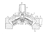
- a turbo blood pump described in Patent Document 1 has a structure as shown in FIG.
- reference numeral 1 denotes a housing, which forms a pump chamber 2 for allowing blood to pass and flow.
- the housing 1 is provided with an inlet port 3 that communicates with an upper portion of the pump chamber 2 and an outlet port 4 that communicates with a side portion of the pump chamber 2.
- An impeller 5 is disposed in the pump chamber 2.
- the impeller 5 includes six vanes 6, a rotating shaft 7, and a ring-shaped annular coupling portion 8.
- FIG. 4 is a top view of the impeller 5 and FIG. 5 is a cross-sectional view of the impeller 5.
- the six vanes include two types of shapes, that is, a main vane 6a and a shorter sub vane 6b, which are alternately arranged.
- the main vane 6a and the sub vane 6b are collectively referred to as vane 6.
- the main vane 6 a has a center side end connected to the rotating shaft 7 and a peripheral side end connected to the annular connecting portion 8.
- the sub vane 6 b has a central end that is not coupled to the rotating shaft 7 but is a free end, and only a peripheral end is coupled to the annular coupling portion 8.
- the number of main vanes 6a is set to a minimum range for supporting the impeller 5 with the rotary shaft 7 and obtaining a sufficient driving force.
- the number of main vanes 6a is set to at least three. 3 shows only the shape along the main vane 6a shown in FIG. 4 for the convenience of illustration.
- the lower end edge of the vane 6 (both the main vane 6a and the sub vane 6b) is arranged so that the apex is along the conical surface with the upward direction. That is, the vane 6 is inclined with respect to the rotating shaft 7 to form a mixed flow pump.
- the shape of the vane 6 is a three-dimensional curved surface. Accordingly, it is possible to realize a blood pump with reduced hemolysis by suppressing cavitation (flow separation, vortex) generated on the outlet side of the vane 6 while having sufficient ejection ability.
- the rotating shaft 7 is rotatably supported by an upper bearing 9 and a lower bearing 10 provided in the housing 1. Therefore, the impeller 5 is supported in a stable state at the vertical position by the upper bearing 9 and the lower bearing 10, and the rotation thereof is stabilized.
- the annular connecting portion 8 is provided with a magnet case 11, and a driven magnet 12 is embedded in the magnet case 11.
- the driven magnets 12 have a columnar shape, and are arranged in the circumferential direction of the annular connecting portion 8 at regular intervals.
- the annular connecting portion 8 and the magnet case 11 form a cylindrical inner peripheral surface.
- a rotor 13 is disposed at the bottom of the housing 1.
- the rotor 13 has a structure in which a substantially cylindrical magnetic coupling portion 15 is provided on the drive shaft 14.
- the drive shaft 14 is rotatably supported and connected to a rotation drive source such as a motor to be rotated. Further, the positional relationship between the rotor 13 and the housing 1 is kept constant by elements not shown.
- a drive magnet 16 is embedded in the upper surface portion of the magnetic coupling portion 15.
- the drive magnets 16 have a cylindrical shape, and are arranged at regular intervals with six pieces in the circumferential direction.
- the driving magnet 16 is disposed so as to be in a positional relationship facing the driven magnet 12 across the wall of the housing 1. Accordingly, a magnetically coupled state is formed between the rotor 13 and the impeller 5, and by rotating the rotor 13, a rotational driving force is transmitted to the impeller 5 through magnetic coupling.
- the upper and lower surfaces of the annular coupling portion 8 on which the driven magnet 12 is installed are not orthogonal to the rotation shaft 7 and are along the same conical surface. Yes.
- the upper surface of the magnetic coupling portion 15 on which the drive magnet 16 is installed is also an inclined surface.
- the driven magnet 12 and the drive magnet 16 form a magnetic coupling on the surface inclined with respect to the rotation axis of the impeller 5, the magnetic attractive force acting between the impeller 5 and the rotor 13 is reduced. It occurs in a direction inclined with respect to the rotation axis of the impeller 5. As a result, the downward load on the lower bearing 10 is reduced.
- the impeller 5 has a space 17 in an inner region of the annular coupling portion 8, and a flow path penetrating vertically between the vanes 6 is formed.
- a pedestal 18 having a cylindrical outer peripheral surface protruding upward, that is, inside the pump chamber 2 is formed at the center of the bottom of the housing 1.
- the pedestal 18 is formed so as to fill the space 17 in the region inside the driven magnet 12 and the annular coupling portion 8 below the impeller 5, and the volume of the space is suppressed to the minimum.
- the upper surface of the pedestal 18 is formed as a conical inclined surface whose apex is directed upward along the lower edge of the vane 6.
- the bottom of the housing 1 around the pedestal 18 is also formed on the same inclined surface.
- the pedestal 18 Since the pedestal 18 is formed, the blood filling amount in the pump chamber 2 is reduced. Further, since the annular connecting portion 8 is not of a size that covers the entire bottom surface of the housing 1 but the space 17 is formed, the impeller 5 becomes light in weight, and the driving force necessary for rotation is reduced.
- the lower bearing 10 is provided at the center of the upper surface of the pedestal 18. The upper bearing 9 is supported at the tips of three bearing columns 19 disposed in the lower end portion of the inlet port 3.
- the above configuration is effective to improve the state where blood stays in the lower part of the impeller 5 and to eliminate the possibility that thrombus may be formed when the blood pump is used for a long time (percutaneous cardiopulmonary assist method, etc.). It is. That is, in the space region inside the annular connecting portion 8, a flow path that penetrates between the vanes 6 is formed, and the blood that flows to the lower portion of the impeller 5 passes through the vicinity of the lower bearing 10 and passes through the vane. This is because an action of flowing out toward the outer diameter direction of 6 is obtained.
- the impeller 5 further has a sealing member 20 arranged at the lower part of the vane 6 in a region extending between the rotary shaft 7 and the annular connecting portion 8.
- the sealing member 20 seals the flow path penetrating between the vane 6 from the space in the region between the rotating shaft 7 and the annular connecting portion 8, leaving a part of the opening 21 around the rotating shaft 7. Yes.
- the sealing member 20 By providing the sealing member 20, the effect of suppressing the formation of thrombus in the vicinity of the lower bearing 10 on the upper surface of the base 18 is improved. That is, the flow of blood on the bottom surface of the housing 1 flowing toward the center of the impeller 5 along the lower surface of the sealing member 20 is strengthened. Since the blood flow then rises through the opening 21 of the sealing member 20, a blood flow having a sufficient speed is formed along the rotary shaft 7 adjacent to the lower bearing 10, and the cleaning effect on the lower bearing 10 is improved. .
- a vertical through-hole is provided in the center of the base 18 to form a bearing mounting hole 22 and an adjustment screw mounting hole 23.
- the lower bearing 10 is mounted in the bearing mounting hole 22, and the adjustment screw 24 is mounted in the adjustment screw mounting hole 23.
- a female screw is formed on the inner peripheral surface of the adjustment screw mounting hole 23, and a male screw is formed on the outer peripheral surface of the adjustment screw 24.
- the housing 1 is divided into an upper half 1a on the side including the inlet port 3 and a lower half 1b on the side including the pedestal 18 at the upper and lower dividing surfaces 25.
- the upper bearing 9 is provided on the upper half 1a.
- the impeller 5 is mounted in the housing 1 by connecting the upper half 1a and the lower half 1b so that the rotary shaft 7 is supported between the upper bearing 9 and the lower bearing 10.
- the position of the adjustment screw 24 can be adjusted by screwing with the adjustment screw mounting hole 23. Accordingly, the lower bearing 10 is mounted in the bearing mounting hole 22, the rotating shaft 7 is supported between the upper bearing 9 and the lower bearing 10, and the upper half 1a and the lower half 1b are coupled, and then the adjusting screw. By rotating 24 and adjusting the vertical position of the lower bearing 10, the inter-bearing distance H between the upper bearing 9 and the lower bearing 10 can be adjusted.
- the rotational torque of the impeller 5 is affected by the distance H between the bearings.
- the distance H between the bearings is not constant due to a slight error in the dimensions of the molded product and the shaft dimension, and there is also an error in the length of the rotating shaft 7. Variation occurs. Therefore, providing the adjusting screw 24 for adjusting the distance H between the bearings is indispensable for stabilizing the quality.
- the adjustment screw 24 is necessary as an element part in addition to the lower bearing 10. Therefore, it is inevitable that the increase in the component cost due to the increase in the number of components and the complexity of the manufacturing process due to the large number of components contribute to the increase in cost.
- the present invention provides a turbo blood pump having a structure capable of improving the structure for adjusting the position of the lower bearing with respect to the rotating shaft of the impeller, reducing the number of parts, and improving the simplicity of the manufacturing process.
- the purpose is to do.
- the turbo blood pump of the present invention includes a housing that forms a pump chamber, an inlet port is provided at an upper portion and an outlet port is provided at a side portion, a rotating shaft, a plurality of vanes, and an annular connecting portion, An inner peripheral end of at least a part of the plurality of vanes is coupled to the rotating shaft, and an outer peripheral end of each vane is formed by projecting an impeller coupled to the annular coupling portion and a bottom wall of the housing upward
- a pedestal having a cylindrical outer peripheral surface corresponding to a space region formed by the cylindrical inner peripheral surface of the annular coupling portion, an upper bearing that rotatably supports an upper end of a rotating shaft of the impeller, and the pedestal
- a lower bearing that is provided on the upper surface of the housing and rotatably supports the lower end of the rotating shaft of the impeller, and is disposed on the outer lower portion of the housing, and rotationally drives the impeller through magnetic coupling with the annular coupling portion.
- a chromatography data is provided on the
- a bearing mounting hole having an inner surface threaded protrusion formed on an inner peripheral surface is provided in the center of the pedestal, and the lower bearing has the lower end of the rotating shaft of the impeller at its upper end.
- an outer surface threaded protrusion is formed on the outer peripheral surface to be screwed with the inner surface threaded protrusion, and is mounted in the bearing mounting hole through the threaded engagement.
- a method for manufacturing a turbo blood pump according to the present invention is a method for manufacturing a turbo blood pump having the above-described configuration, wherein the lower bearing is mounted in the bearing mounting hole, and the rotating shaft is connected to the upper bearing and the lower bearing. After the impeller is mounted in the housing so as to be supported in between, the lower bearing exposed below the bearing mounting hole is rotated to screw the outer thread protrusion and the inner thread protrusion. An operation for adjusting the position of the lower bearing in the vertical direction is performed.
- FIG. 1 is a cross-sectional view of a turbo blood pump according to an embodiment of the present invention.
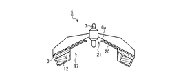
- FIG. 2A is a perspective view showing a configuration of a lower bearing of the turbo blood pump.
- FIG. 2B is a perspective view showing a configuration of a pedestal in the housing of the turbo blood pump.
- FIG. 3 is a cross-sectional view of a conventional turbo blood pump.
- FIG. 4 is a top view of the impeller of the turbo blood pump of FIG.
- FIG. 5 is a cross-sectional view of the impeller.
- FIG. 6 is a cross-sectional view showing the bearing structure of the turbo blood pump of FIG.
- the present invention can take the following aspects based on the above configuration.
- the inner surface thread protrusion forms two threads, and the threads of each thread are set to a length equal to or less than a half circumference in the circumferential direction of the bearing mounting hole.
- the screw threads are preferably arranged in regions that do not overlap each other in the circumferential direction.
- the thread of each strip forming the inner surface thread protrusion is set to a length of a half circumference in the circumferential direction of the bearing mounting hole. According to this configuration, it is easy to form an internal thread protrusion in the bearing mounting hole of the pedestal by injection molding and eliminate the need for additional work on the pedestal after injection molding.
- the bearing mounting hole is a through hole, and an engaging portion with a tool for rotating the lower bearing is provided at a lower end portion of the lower bearing exposed below the bearing mounting hole.
- the impeller is mounted in the pump chamber so that the rotating shaft is supported between the upper bearing and the lower bearing, and the position of the lower bearing in the bearing mounting hole is adjusted to And the process of appropriately setting the distance between the lower bearing and the lower bearing.
- a gap between the inner peripheral surface of the bearing mounting hole and the outer peripheral surface of the lower bearing is sealed with an adhesive on the lower end side of the mounted lower bearing.
- the lower end edge of the vane has an inclination that becomes higher toward the rotation axis, and the impeller is formed with a conical inclined surface along the inclination of the lower end edge of the vane, and the plurality of vanes
- a sealing member that restricts a flow path between the rotating shaft and a region around the rotating shaft is provided at a lower portion of the vane, and the lower bearing has an upper surface that forms an inclined surface along the inclined surface of the sealing member,
- the diameter of the lower bearing can be increased by replacing a part of the upper surface of the pedestal that forms the flow path between the sealing member and the upper surface of the lower bearing.
- the housing is formed by dividing the housing into an upper half on the side including the inlet port and a lower half on the side including the pedestal, and the upper bearing. Is attached to the upper half body, and the upper half body and the lower half body are coupled to each other so that the rotating shaft is supported between the upper bearing and the lower bearing. It may include a step of mounting inside. According to this process, it is possible to easily perform the operation of mounting the impeller in the pump chamber so that the rotating shaft is supported between the upper bearing and the lower bearing.
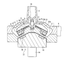
- FIG. 1 is a cross-sectional view showing a turbo blood pump according to Embodiment 1 of the present invention.
- the basic structure of this turbo blood pump is the same as that of the conventional example shown in FIGS. Therefore, elements similar to those shown in FIGS. 3 to 5 are denoted by the same reference numerals, and the repeated description is simplified.
- the impeller 5 disposed in the pump chamber 2 formed by the housing 1 has a plurality of vanes 6 as in the conventional example, and at least a part of the inner peripheral end thereof is The outer peripheral end of each vane 6 is coupled to an annular connecting portion 8 that is coupled to the rotary shaft 7 and forms an outer peripheral edge.
- the rotary shaft 7 is rotatably supported by the upper bearing 9 and the lower bearing 26.
- the lower bearing 26 is mounted in a bearing mounting hole 28 provided in the upper surface portion of the base 27.
- the configuration of the lower bearing 26 is shown in a perspective view in FIG. 2A, and the configuration of a pedestal 27 having a bearing mounting hole 28 is shown in a perspective view in FIG. 2B.
- the housing 1 is divided into two parts by an upper and lower dividing surface 25 into an upper half 1 a including the inlet port 3 and a lower half 1 b including the pedestal 27.
- the upper bearing 9 is provided on the upper half 1a.
- the impeller 5 is mounted in the housing 1 by connecting the upper half 1a and the lower half 1b so that the rotary shaft 7 is supported between the upper bearing 9 and the lower bearing 26.
- the pedestal 27 is formed by projecting upward the central portion inside the bottom wall of the housing 1, and has a cylindrical outer peripheral surface corresponding to a space region formed by the cylindrical inner peripheral surface of the annular coupling portion 8. .
- a part of the upper surface of the pedestal 27 is formed by the upper surface of the lower bearing 26, and is a conical inclined surface whose apex is directed upward. Note that the surface of the bottom surface of the housing 1 that faces the annular connecting portion 8 is also an inclined surface along the annular connecting portion 8.
- the impeller 5 includes a sealing member 20 disposed below the vane 6.
- the blocking member 20 forms a conical inclined surface along the inclination of the lower end edge of the vane 6.
- the sealing member 20 seals the space in the inner region of the annular coupling portion 8 leaving the opening 21 around the rotating shaft 7.
- a through hole is provided in the central portion of the pedestal 27 to form a bearing mounting hole 28.
- the lower bearing 26 has an upper large-diameter portion 29 whose outer peripheral diameter is larger than that of the bearing mounting hole 28, and a cylindrical portion that forms a lower portion thereof and whose outer peripheral diameter is smaller than that of the bearing mounting hole 28. 30.
- a bearing 31 that supports the lower end of the rotating shaft 7 of the impeller 5 is formed at the upper end of the lower bearing 26.
- An internal thread protrusion 28 a is formed on the inner peripheral surface of the bearing mounting hole 28.
- an outer surface thread protrusion 26a that is screwed with the inner surface thread protrusion 28a is formed.
- the large diameter portion 29 of the lower bearing 26 forms an inclined surface whose upper surface is along the inclined surface of the sealing member 20.
- the lower bearing 26 is mounted in the bearing mounting hole 28 by screwing the outer thread protrusion 26a with the inner thread protrusion 28a. Since the bearing mounting hole 28 is a through-hole, when the lower bearing 26 is mounted in the bearing mounting hole 28, the lower end thereof is exposed below the bearing mounting hole 28. An engaging portion 32 (FIG. 1) with a tool for rotating the lower bearing 26 is provided at the lower end portion of the exposed lower bearing 26. Accordingly, in the manufacturing process, an operation of rotating the lower bearing 26 by engaging the tool with the engaging portion 32 is performed. As a result, the vertical position of the lower bearing 26 in the bearing mounting hole 28 can be adjusted via the screwing of the outer thread protrusion 26a and the inner thread protrusion 28a.
- the gap between the inner peripheral surface of the bearing mounting hole 28 and the outer peripheral surface of the lower bearing 26 is blocked by an adhesive. This is because the pump chamber 2 communicates with the outside through a gap between the inner peripheral surface of the bearing mounting hole 28 and the outer peripheral surface of the lower bearing 26 when the lower bearing 26 is simply mounted.
- the bearing mounting hole 28 be a through hole. That is, it is also possible to configure so that the adjustment for rotating the lower bearing 26 is performed by another method.
- the lower bearing 26 can be rotated using the opening of the inlet port 3.
- the internal thread protrusion 28a forms two threads, and the thread of each thread is set to the length of the half circumference in the circumferential direction of the bearing mounting hole 28.
- the threads of the respective strips are arranged in regions that do not overlap with each other in the circumferential direction.
- Each thread of the inner surface thread protrusion 28a may have a length less than a half circumference. However, it is necessary to secure a length that allows an appropriate screwed state with the outer surface screw projection 26a.
- the structure for adjusting the position of the lower bearing 26 is formed with a small number of parts, and no additional work is required for the pedestal 27 after injection molding. Thereby, the lower bearing structure which can adjust rotational torque at lower cost can be provided.
- the turbo blood pump of the present embodiment can be configured using the following materials as an example.
- a synthetic resin such as polycarbonate, polyethylene terephthalate, polysulfone, etc. is used in terms of weight reduction, easy moldability, strength, dimensional stability, and the like. Can do.
- the material of the bearing is not particularly limited as long as it has high wear resistance.
- high durability plastics such as ultra high molecular weight polyethylene and polyether ether ketone (PEEK) can be suitably used.
- PEEK polyether ether ketone
- SUS stainless steel
- the turbo blood pump of the present invention can be manufactured at a low cost for adjusting the position of the lower bearing with respect to the rotation shaft of the impeller, and is useful as a blood pump used for extracorporeal blood circulation in an oxygenator or the like.
Abstract
Description
図1は、本発明の実施の形態1におけるターボ式血液ポンプを示す断面図である。このターボ式血液ポンプの基本的な構造は、図3~図5に示した従来例のものと同様である。従って、図3~図5に示した要素と同様の要素については、同一の参照符号を付して、説明の繰り返しを簡略化する。 (Embodiment)
FIG. 1 is a cross-sectional view showing a turbo blood pump according to
1a 上半体
1b 下半体
2 ポンプ室
3 入口ポート
4 出口ポート
5 インペラ
6 ベーン
6a 主ベーン
6b 副ベーン
7 回転軸
8 環状連結部
9 上部軸受け
10、26 下部軸受け
11 磁石ケース
12 従動磁石
13 ロータ
14 駆動軸
15 磁気結合部
16 駆動磁石
17 空間
18、27 台座
19 軸受け支柱
20 封鎖部材
21 開口部
22、28 軸受け装着孔
23 調節ネジ装着孔
24 調節ネジ
25 上下分割面
26a 外面ネジ突起
28a 内面ネジ突起
29 径大部
30 円筒部
31 軸受け部 DESCRIPTION OF
Claims (8)
- ポンプ室を形成し、上部に入口ポートが設けられ、側部に出口ポートが設けられたハウジングと、
回転軸、複数のベーン及び環状連結部を有し、前記複数のベーンの少なくとも一部の内周端は前記回転軸と結合し、前記各ベーンの外周端は前記環状連結部に結合しているインペラと、
前記ハウジングの底部壁を上方に突出させて形成され、前記環状連結部の円筒状の内周面が形成する空間領域に対応する円筒状の外周面を有する台座と、
前記インペラの回転軸の上端を回転自在に支持する上部軸受けと、
前記台座の上面部に設けられ前記インペラの回転軸の下端を回転自在に支持する下部軸受けと、
前記ハウジングの外側下部に配置され、前記環状連結部との磁気結合を介して前記インペラを回転駆動するロータとを備えたターボ式血液ポンプにおいて、
前記台座の中央部には、内周面に内面ネジ突起が形成された軸受け装着孔が設けられ、
前記下部軸受けは、その上端に前記インペラの回転軸の下端を支持する軸受け部を有するとともに、外周面に前記内面ネジ突起と螺合する外面ネジ突起が形成され、その螺合を介して前記軸受け装着孔に装着されていることを特徴とするターボ式血液ポンプ。 A housing that forms a pump chamber and is provided with an inlet port at the top and an outlet port at the side;
A rotating shaft, a plurality of vanes, and an annular connecting portion, wherein at least some of the inner peripheral ends of the plurality of vanes are connected to the rotating shaft, and the outer peripheral ends of the vanes are connected to the annular connecting portion; Impeller,
A pedestal having a cylindrical outer peripheral surface formed by projecting the bottom wall of the housing upward and corresponding to a space region formed by the cylindrical inner peripheral surface of the annular coupling portion;
An upper bearing that rotatably supports the upper end of the rotating shaft of the impeller;
A lower bearing which is provided on the upper surface of the pedestal and rotatably supports the lower end of the rotating shaft of the impeller;
In the turbo blood pump, which is disposed at the outer lower portion of the housing and includes a rotor that rotationally drives the impeller through magnetic coupling with the annular coupling portion,
In the central part of the pedestal is provided a bearing mounting hole in which an internal thread protrusion is formed on the inner peripheral surface,
The lower bearing has a bearing portion that supports a lower end of the rotating shaft of the impeller at an upper end thereof, and an outer surface threaded protrusion that is screwed with the inner surface threaded protrusion is formed on an outer peripheral surface. A turbo blood pump characterized by being mounted in a mounting hole. - 前記内面ネジ突起は2条のネジ山を形成し、各条のネジ山は前記軸受け装着孔の周方向における半周以下の長さに設定され、各条のネジ山は、相互に周方向の重ならない領域に配置されている請求項1に記載のターボ式血液ポンプ。 The inner surface thread projections form two threads, and each thread is set to a length not more than a half circumference in the circumferential direction of the bearing mounting hole. The turbo type blood pump according to claim 1, wherein the turbo blood pump is disposed in a region that does not become necessary.
- 前記内面ネジ突起を形成する各条のネジ山は、前記軸受け装着孔の周方向における半周の長さに設定されている請求項2に記載のターボ式血液ポンプ。 The turbo blood pump according to claim 2, wherein the thread of each strip forming the internal thread protrusion is set to a length of a half circumference in the circumferential direction of the bearing mounting hole.
- 前記軸受け装着孔は貫通孔であり、前記軸受け装着孔の下方に露出する前記下部軸受けの下端部に、前記下部軸受けを回動させるための工具との係合部が設けられている請求項1~3のいずれか1項に記載のターボ式血液ポンプ。 2. The bearing mounting hole is a through hole, and an engaging portion with a tool for rotating the lower bearing is provided at a lower end portion of the lower bearing exposed below the bearing mounting hole. 4. The turbo blood pump according to any one of items 1 to 3.
- 装着された前記下部軸受けの下端側において、前記軸受け装着孔の内周面と前記下部軸受けの外周面の間の隙間が接着材により目止めされている請求項4に記載のターボ式血液ポンプ。 The turbo blood pump according to claim 4, wherein a gap between an inner peripheral surface of the bearing mounting hole and an outer peripheral surface of the lower bearing is sealed with an adhesive on a lower end side of the mounted lower bearing.
- 前記ベーンの下端縁は、前記回転軸に向かって高くなる傾斜を持ち、
前記インペラには、前記ベーンの下端縁の傾斜に沿った円錐面状の傾斜面を形成し、前記複数のベーンの間の流路を前記回転軸の周囲の領域に制限する封鎖部材が前記ベーンの下部に設けられ、
前記下部軸受けは、上面が前記封鎖部材の傾斜面に沿った傾斜面を形成し、外周径が前記軸受け装着孔よりも大きい上側径大部と、その下部を形成し外周径が前記軸受け装着孔よりも小さく、外周面に前記外面ネジ突起が形成された下側円筒部とを含む請求項1~5のいずれか1項に記載のターボ式血液ポンプ。 The lower edge of the vane has an inclination that increases toward the rotation axis,
The impeller includes a sealing member that forms a conical inclined surface along an inclination of a lower end edge of the vane and restricts a flow path between the plurality of vanes to a region around the rotating shaft. At the bottom of the
The lower bearing has an upper surface forming an inclined surface along the inclined surface of the sealing member, an outer peripheral diameter larger than the bearing mounting hole, and a lower portion thereof, and the outer peripheral diameter is the bearing mounting hole. The turbo blood pump according to any one of claims 1 to 5, further comprising a lower cylindrical portion that is smaller than the lower cylindrical portion and has the outer surface thread projection formed on an outer peripheral surface thereof. - 請求項1に記載のターボ式血液ポンプの製造方法であって、
前記軸受け装着孔を貫通孔とし、
前記下部軸受けを前記軸受け装着孔に装着し、
前記回転軸が前記上部軸受と前記下部軸受けの間に支持された状態になるように前記インペラを前記ハウジング内に装着した後、
前記軸受け装着孔の下方に露出した前記下部軸受けを回動させて、前記外面ネジ突起と前記内面ネジ突起の螺合を介して、前記下部軸受けの上下方向の位置を調整する操作を行うことを特徴とするターボ式血液ポンプの製造方法。 It is a manufacturing method of the turbo type blood pump according to claim 1,
The bearing mounting hole is a through hole,
Attaching the lower bearing to the bearing mounting hole,
After mounting the impeller in the housing so that the rotating shaft is supported between the upper bearing and the lower bearing,
The lower bearing exposed below the bearing mounting hole is rotated, and an operation of adjusting the vertical position of the lower bearing is performed through screwing of the outer surface screw protrusion and the inner surface screw protrusion. A method for producing a turbo blood pump. - 前記ハウジングを前記入口ポートを含む側の上半体と前記台座を含む側の下半体とに2分割して形成し、前記上部軸受けを前記上半体に設け、
前記回転軸が前記上部軸受と前記下部軸受けの間に支持された状態になるように前記上半体と前記下半体とを結合させることにより、前記インペラを前記ハウジング内に装着する請求項7に記載のターボ式血液ポンプの製造方法。 Forming the housing in two divided into an upper half on the side including the inlet port and a lower half on the side including the pedestal, and providing the upper bearing on the upper half;
8. The impeller is mounted in the housing by coupling the upper half and the lower half so that the rotating shaft is supported between the upper bearing and the lower bearing. A method for producing a turbo blood pump according to claim 1.
Priority Applications (2)
| Application Number | Priority Date | Filing Date | Title |
|---|---|---|---|
| BR112013020840A BR112013020840A2 (en) | 2011-02-24 | 2012-02-23 | turbo blood pump and method to produce the same |
| JP2013501115A JP5673795B2 (en) | 2011-02-24 | 2012-02-23 | Turbo blood pump and method for manufacturing the same |
Applications Claiming Priority (2)
| Application Number | Priority Date | Filing Date | Title |
|---|---|---|---|
| JP2011038583 | 2011-02-24 | ||
| JP2011-038583 | 2011-02-24 |
Publications (1)
| Publication Number | Publication Date |
|---|---|
| WO2012115184A1 true WO2012115184A1 (en) | 2012-08-30 |
Family
ID=46720958
Family Applications (1)
| Application Number | Title | Priority Date | Filing Date |
|---|---|---|---|
| PCT/JP2012/054407 WO2012115184A1 (en) | 2011-02-24 | 2012-02-23 | Turbo blood pump and method for producing same |
Country Status (3)
| Country | Link |
|---|---|
| JP (1) | JP5673795B2 (en) |
| BR (1) | BR112013020840A2 (en) |
| WO (1) | WO2012115184A1 (en) |
Cited By (2)
| Publication number | Priority date | Publication date | Assignee | Title |
|---|---|---|---|---|
| WO2014060765A1 (en) * | 2012-10-18 | 2014-04-24 | Calon Cardio Technology Ltd | Centrifugal pump |
| EP3195887A4 (en) * | 2014-09-19 | 2018-03-28 | Terumo Kabushiki Kaisha | Centrifugal pump |
Families Citing this family (5)
| Publication number | Priority date | Publication date | Assignee | Title |
|---|---|---|---|---|
| AU2018280236A1 (en) | 2017-06-07 | 2020-01-16 | Shifamed Holdings, Llc | Intravascular fluid movement devices, systems, and methods of use |
| JP7319266B2 (en) | 2017-11-13 | 2023-08-01 | シファメド・ホールディングス・エルエルシー | Intravascular fluid transfer devices, systems and methods of use |
| CN112004563A (en) | 2018-02-01 | 2020-11-27 | 施菲姆德控股有限责任公司 | Intravascular blood pump and methods of use and manufacture |
| US11654275B2 (en) | 2019-07-22 | 2023-05-23 | Shifamed Holdings, Llc | Intravascular blood pumps with struts and methods of use and manufacture |
| US11724089B2 (en) | 2019-09-25 | 2023-08-15 | Shifamed Holdings, Llc | Intravascular blood pump systems and methods of use and control thereof |
Citations (6)
| Publication number | Priority date | Publication date | Assignee | Title |
|---|---|---|---|---|
| US4507048A (en) * | 1979-03-16 | 1985-03-26 | Jacques Belenger | Centrifugal clinical blood pump |
| JPH08501366A (en) * | 1992-07-30 | 1996-02-13 | スピン コーポレイション | Spiral blood pump |
| JPH11504549A (en) * | 1996-02-20 | 1999-04-27 | クリトン・メディカル・インコーポレーテッド | Sealless rotary blood pump with passive magnetic radial bearing and axial bearing immersed in blood |
| US6227820B1 (en) * | 1999-10-05 | 2001-05-08 | Robert Jarvik | Axial force null position magnetic bearing and rotary blood pumps which use them |
| JP2008183229A (en) * | 2007-01-30 | 2008-08-14 | Jms Co Ltd | Turbo type blood pump |
| JP2010207346A (en) * | 2009-03-09 | 2010-09-24 | Jms Co Ltd | Turbo blood pump |
-
2012
- 2012-02-23 JP JP2013501115A patent/JP5673795B2/en active Active
- 2012-02-23 WO PCT/JP2012/054407 patent/WO2012115184A1/en active Application Filing
- 2012-02-23 BR BR112013020840A patent/BR112013020840A2/en not_active IP Right Cessation
Patent Citations (6)
| Publication number | Priority date | Publication date | Assignee | Title |
|---|---|---|---|---|
| US4507048A (en) * | 1979-03-16 | 1985-03-26 | Jacques Belenger | Centrifugal clinical blood pump |
| JPH08501366A (en) * | 1992-07-30 | 1996-02-13 | スピン コーポレイション | Spiral blood pump |
| JPH11504549A (en) * | 1996-02-20 | 1999-04-27 | クリトン・メディカル・インコーポレーテッド | Sealless rotary blood pump with passive magnetic radial bearing and axial bearing immersed in blood |
| US6227820B1 (en) * | 1999-10-05 | 2001-05-08 | Robert Jarvik | Axial force null position magnetic bearing and rotary blood pumps which use them |
| JP2008183229A (en) * | 2007-01-30 | 2008-08-14 | Jms Co Ltd | Turbo type blood pump |
| JP2010207346A (en) * | 2009-03-09 | 2010-09-24 | Jms Co Ltd | Turbo blood pump |
Cited By (4)
| Publication number | Priority date | Publication date | Assignee | Title |
|---|---|---|---|---|
| WO2014060765A1 (en) * | 2012-10-18 | 2014-04-24 | Calon Cardio Technology Ltd | Centrifugal pump |
| CN104902939A (en) * | 2012-10-18 | 2015-09-09 | 卡龙心脏科技有限公司 | Centrifugal pump |
| EP3195887A4 (en) * | 2014-09-19 | 2018-03-28 | Terumo Kabushiki Kaisha | Centrifugal pump |
| US10363348B2 (en) | 2014-09-19 | 2019-07-30 | Terumo Kabushiki Kaisha | Centrifugal pump |
Also Published As
| Publication number | Publication date |
|---|---|
| JPWO2012115184A1 (en) | 2014-07-07 |
| BR112013020840A2 (en) | 2016-10-04 |
| JP5673795B2 (en) | 2015-02-18 |
Similar Documents
| Publication | Publication Date | Title |
|---|---|---|
| JP5673795B2 (en) | Turbo blood pump and method for manufacturing the same | |
| JP4655231B2 (en) | Turbo blood pump | |
| JP4548450B2 (en) | Turbo blood pump | |
| JP5267227B2 (en) | Turbo blood pump | |
| US8523539B2 (en) | Centrifugal pump | |
| JP6134702B2 (en) | Centrifugal pump and centrifugal pump manufacturing method | |
| KR20190004384A (en) | Reciprocating fluid agitator | |
| CN112524038B (en) | Centrifugal pump and pump housing | |
| JP5590213B2 (en) | Turbo blood pump | |
| JP2018134428A (en) | Centrifugal Pump | |
| JP2018061600A (en) | Centrifugal type blood pump | |
| US20180369467A1 (en) | Blood pump | |
| JP5828459B2 (en) | Centrifugal blood pump | |
| TWI390110B (en) | Vane pump | |
| JP2017048703A (en) | Centrifugal Pump | |
| JP2019117174A (en) | Impeller type flow rate sensor and flow rate control system | |
| JP5885986B2 (en) | Pump device | |
| JP2016188591A (en) | Centrifugal pump device | |
| JP2017158899A (en) | Centrifugal blood pump | |
| JP6720629B2 (en) | Centrifugal pump and method of manufacturing centrifugal pump | |
| JP2016188593A (en) | Centrifugal pump device | |
| CN105736361A (en) | Gear pump | |
| JP2017172500A (en) | Centrifugal Pump | |
| JP2017172499A (en) | Centrifugal Pump | |
| JP2015084792A (en) | Housing and blood pump |
Legal Events
| Date | Code | Title | Description |
|---|---|---|---|
| 121 | Ep: the epo has been informed by wipo that ep was designated in this application |
Ref document number: 12749753 Country of ref document: EP Kind code of ref document: A1 |
|
| ENP | Entry into the national phase |
Ref document number: 2013501115 Country of ref document: JP Kind code of ref document: A |
|
| NENP | Non-entry into the national phase |
Ref country code: DE |
|
| REG | Reference to national code |
Ref country code: BR Ref legal event code: B01A Ref document number: 112013020840 Country of ref document: BR |
|
| 122 | Ep: pct application non-entry in european phase |
Ref document number: 12749753 Country of ref document: EP Kind code of ref document: A1 |
|
| ENP | Entry into the national phase |
Ref document number: 112013020840 Country of ref document: BR Kind code of ref document: A2 Effective date: 20130815 |