WO2012144243A1 - Ultrasound imaging apparatus - Google Patents
Ultrasound imaging apparatus Download PDFInfo
- Publication number
- WO2012144243A1 WO2012144243A1 PCT/JP2012/051259 JP2012051259W WO2012144243A1 WO 2012144243 A1 WO2012144243 A1 WO 2012144243A1 JP 2012051259 W JP2012051259 W JP 2012051259W WO 2012144243 A1 WO2012144243 A1 WO 2012144243A1
- Authority
- WO
- WIPO (PCT)
- Prior art keywords
- transmission
- signal
- imaging apparatus
- ultrasonic
- channels
- Prior art date
Links
Images


Classifications
-
- A—HUMAN NECESSITIES
- A61—MEDICAL OR VETERINARY SCIENCE; HYGIENE
- A61B—DIAGNOSIS; SURGERY; IDENTIFICATION
- A61B8/00—Diagnosis using ultrasonic, sonic or infrasonic waves
- A61B8/13—Tomography
- A61B8/14—Echo-tomography
-
- A—HUMAN NECESSITIES
- A61—MEDICAL OR VETERINARY SCIENCE; HYGIENE
- A61B—DIAGNOSIS; SURGERY; IDENTIFICATION
- A61B8/00—Diagnosis using ultrasonic, sonic or infrasonic waves
- A61B8/48—Diagnostic techniques
-
- A—HUMAN NECESSITIES
- A61—MEDICAL OR VETERINARY SCIENCE; HYGIENE
- A61B—DIAGNOSIS; SURGERY; IDENTIFICATION
- A61B8/00—Diagnosis using ultrasonic, sonic or infrasonic waves
- A61B8/52—Devices using data or image processing specially adapted for diagnosis using ultrasonic, sonic or infrasonic waves
- A61B8/5207—Devices using data or image processing specially adapted for diagnosis using ultrasonic, sonic or infrasonic waves involving processing of raw data to produce diagnostic data, e.g. for generating an image
-
- A—HUMAN NECESSITIES
- A61—MEDICAL OR VETERINARY SCIENCE; HYGIENE
- A61B—DIAGNOSIS; SURGERY; IDENTIFICATION
- A61B8/00—Diagnosis using ultrasonic, sonic or infrasonic waves
- A61B8/54—Control of the diagnostic device
-
- G—PHYSICS
- G01—MEASURING; TESTING
- G01S—RADIO DIRECTION-FINDING; RADIO NAVIGATION; DETERMINING DISTANCE OR VELOCITY BY USE OF RADIO WAVES; LOCATING OR PRESENCE-DETECTING BY USE OF THE REFLECTION OR RERADIATION OF RADIO WAVES; ANALOGOUS ARRANGEMENTS USING OTHER WAVES
- G01S15/00—Systems using the reflection or reradiation of acoustic waves, e.g. sonar systems
- G01S15/88—Sonar systems specially adapted for specific applications
- G01S15/89—Sonar systems specially adapted for specific applications for mapping or imaging
- G01S15/8906—Short-range imaging systems; Acoustic microscope systems using pulse-echo techniques
- G01S15/8909—Short-range imaging systems; Acoustic microscope systems using pulse-echo techniques using a static transducer configuration
- G01S15/8915—Short-range imaging systems; Acoustic microscope systems using pulse-echo techniques using a static transducer configuration using a transducer array
- G01S15/8927—Short-range imaging systems; Acoustic microscope systems using pulse-echo techniques using a static transducer configuration using a transducer array using simultaneously or sequentially two or more subarrays or subapertures
-
- G—PHYSICS
- G01—MEASURING; TESTING
- G01S—RADIO DIRECTION-FINDING; RADIO NAVIGATION; DETERMINING DISTANCE OR VELOCITY BY USE OF RADIO WAVES; LOCATING OR PRESENCE-DETECTING BY USE OF THE REFLECTION OR RERADIATION OF RADIO WAVES; ANALOGOUS ARRANGEMENTS USING OTHER WAVES
- G01S7/00—Details of systems according to groups G01S13/00, G01S15/00, G01S17/00
- G01S7/52—Details of systems according to groups G01S13/00, G01S15/00, G01S17/00 of systems according to group G01S15/00
- G01S7/52017—Details of systems according to groups G01S13/00, G01S15/00, G01S17/00 of systems according to group G01S15/00 particularly adapted to short-range imaging
- G01S7/52023—Details of receivers
- G01S7/52036—Details of receivers using analysis of echo signal for target characterisation
- G01S7/52038—Details of receivers using analysis of echo signal for target characterisation involving non-linear properties of the propagation medium or of the reflective target
-
- G—PHYSICS
- G01—MEASURING; TESTING
- G01S—RADIO DIRECTION-FINDING; RADIO NAVIGATION; DETERMINING DISTANCE OR VELOCITY BY USE OF RADIO WAVES; LOCATING OR PRESENCE-DETECTING BY USE OF THE REFLECTION OR RERADIATION OF RADIO WAVES; ANALOGOUS ARRANGEMENTS USING OTHER WAVES
- G01S7/00—Details of systems according to groups G01S13/00, G01S15/00, G01S17/00
- G01S7/52—Details of systems according to groups G01S13/00, G01S15/00, G01S17/00 of systems according to group G01S15/00
- G01S7/52017—Details of systems according to groups G01S13/00, G01S15/00, G01S17/00 of systems according to group G01S15/00 particularly adapted to short-range imaging
- G01S7/52046—Techniques for image enhancement involving transmitter or receiver
- G01S7/52047—Techniques for image enhancement involving transmitter or receiver for elimination of side lobes or of grating lobes; for increasing resolving power
Definitions
- the present invention relates to harmonic imaging in an ultrasonic imaging apparatus.
- Imaging technology using ultrasonic waves is the conversion of electrical signals into ultrasonic waves by electroacoustic transducers (transducers), irradiating the ultrasonic waves on the object, and the reflected waves (echoes) reflected by the object are electroacoustic again. It is converted into an electric signal by being received by a conversion element, and image data generated based on the signal and time-series data are displayed on a monitor.
- the ultrasonic waves are partially reflected at the boundary where the acoustic impedance is different while traveling through the object, and an echo signal having an intensity depending on the difference in impedance is generated. Therefore, the boundary surface can be displayed as a tomographic image of the object.
- Such an imaging technique is widely used as a non-destructive inspection of a structure or a diagnostic apparatus for imaging a tomographic image of a living body with minimal invasiveness.
- the sound wave waveform As the irradiated ultrasonic wave propagates through the object, the sound wave waveform is distorted. This is due to a phenomenon caused by acoustic nonlinearity in which the high sound pressure portion of the transmitted sound wave waveform advances fast and the low pressure portion advances slowly. Since this phenomenon is accumulated as the sound wave propagates longer, the waveform distortion becomes stronger.
- An ultrasonic diagnostic apparatus is equipped with a higher image quality imaging method using this acoustic nonlinearity.
- an ultrasonic wave is irradiated into a living body, waveform distortion occurs in the process of propagation, and a nonlinear component composed of harmonics is generated in addition to the fundamental frequency component of the irradiated sound wave. Since this nonlinear component is generated approximately in proportion to the square of the amplitude of the fundamental sound pressure, it can be imaged with a greater difference in brightness of the image than in the normal imaging method using the fundamental wave, and an image with high resolution can be obtained. can get. Imaging for imaging such a nonlinear component of biological tissue is called THI (Tissue harmonic imaging).
- the reflected echo intensity due to the generated nonlinear component is smaller than that of the fundamental wave component. Therefore, in order to image only with a non-linear component, it is necessary to separate the non-linear component from the fundamental wave component and extract the non-linear component.
- a method for extracting a non-linear component a method for separating a non-linear component using a filter (for example, Patent Document 1), a PI (Pulse inversion) method (for example, Patent Document 2), and an amplitude modulation method (for example, Patent Document) 3) is known. These techniques are briefly described below.
- the PI (Pulse inversion) method is a method of transmitting two ultrasonic pulses having the sound pressure waveform inverted to each other to the same part of a living body and adding their reflected echoes together. Since the fundamental wave components behave linearly, when transmission pulses that are inverted with respect to each other are transmitted, the fundamental wave components of the reflected echoes are also inverted with each other and canceled by adding them together. On the other hand, since the nonlinear component (second harmonic component) is distorted differently depending on whether the sound pressure is positive or negative, even if an inverted transmission pulse is transmitted, it does not become an inverted waveform and is not canceled even if they are added together. Therefore, when the reflected echoes of the inverted transmission pulse are added together, only the nonlinear component remains.
- the amplitude modulation method transmits ultrasonic waves twice in the same manner as the PI method, but the second transmission pulse does not invert the sound pressure waveform, but the sound pressure level. (Amplitude) is reduced from the first transmission pulse. For example, assume that the amplitude is halved. Since the nonlinear component (second harmonic component) is generated in proportion to the square of the sound pressure of the fundamental component, the nonlinear component in the echo signal of the second transmission is 1 / of the echo signal of the first transmission. The sound pressure is 4. Therefore, by doubling the second transmission echo signal and subtracting it from the first transmission echo signal, the fundamental wave component is canceled and only the nonlinear component remains.
- the waveform of the transmission pulse is formed by an input voltage signal to the electroacoustic transducer. This is done by inverting the waveform.
- the electroacoustic transducer has nonlinearity, a completely inverted transmission pulse cannot be formed even if an inverted input signal is input.
- elements for amplifying the voltage are arranged in the transmission circuit, these elements also have non-linearity. For this reason, a completely inverted transmission pulse cannot be formed due to the nonlinearity of the electroacoustic transducer and the nonlinearity of the transmission circuit, and the linear component in the echo signal cannot be completely canceled. Extraction becomes difficult.
- the amplitude modulation method it is necessary to modulate the amplitude of the second transmission pulse with respect to the first transmission pulse, for example, to halve the amplitude, but when the electroacoustic transducer or the transmission circuit has nonlinearity as described above Even if the amplitude of the input signal is halved, there arises a problem similar to the PI method in which a transmission pulse in which only the amplitude is halved cannot be formed.
- An object of the present invention is to enable THI in which more nonlinear components are extracted even when an electroacoustic transducer having high nonlinearity is used.
- the ultrasonic imaging apparatus delivers a transmission signal to a plurality of electroacoustic transducers and drives it to transmit an ultrasonic beam to a predetermined position of the imaging target, and an echo of the ultrasonic beam from the imaging target
- a reception unit that receives a signal by a plurality of electroacoustic transducers, obtains a reception signal, a signal processing unit that arithmetically processes the reception signal to generate an image, and a control unit that controls the transmission unit and the signal processing unit Have.
- the control unit transmits the ultrasonic beam twice from the transmission unit to the same position of the imaging target, causes the signal processing unit to subtract the reception signal obtained for each two transmissions, and performs a calculation such as reception signal
- the nonlinear component contained in is extracted.
- one transmission is driven by transmitting a transmission signal from the transmission unit to all the electroacoustic transducers having a predetermined area among the plurality of electroacoustic transducers, Only a part of the electroacoustic transducer having a predetermined area is selectively delivered and driven.
- the present invention enables THI that excludes non-linearity caused by any device such as an electroacoustic transducer or a transmission circuit.
- FIG. 1 is a block diagram showing the overall configuration of an ultrasonic imaging apparatus according to a first embodiment of the present invention.
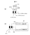
- FIG. 2 is a block diagram of a transmission beamformer of the apparatus of FIG. (A) to (E) are explanatory diagrams showing examples of drive channel patterns when performing imaging according to the first embodiment.
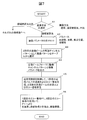
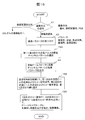
- 6 is a flowchart illustrating a flow of an imaging operation according to the first embodiment.
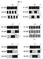
- the table which shows the drive channel pattern which can suppress a grating lobe for every imaging parameter in 2nd Embodiment.
- FIG. 6 is a flowchart illustrating a flow of an imaging operation according to the second embodiment.
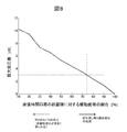
- the graph which showed the maximum sound pressure difference when driving all the channels in a transmission opening part, and driving a part in 2nd Embodiment, changing the drive area.
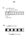
- (A) Explanatory drawing which shows the structure which provided the subchannel in the channel of 3rd Embodiment
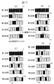
- (A)-(E) Explanatory drawing which shows the drive channel pattern in the case of arranging a channel in two dimensions of 4th Embodiment. Explanatory drawing which shows the frequency band of the filter of 5th Embodiment. 10 is a flowchart illustrating a flow of an imaging operation according to a sixth embodiment.
- the following ultrasonic imaging apparatus is provided as a first aspect. That is, a transmission unit that transmits and transmits transmission signals to a plurality of electroacoustic transducers and transmits an ultrasonic beam to a predetermined position of the imaging target, and an echo of the ultrasonic beam from the imaging target is transmitted to the plurality of electroacoustic transducers A receiving unit that receives the received signal and obtains a received signal, a signal processing unit that performs arithmetic processing on the received signal to generate an image, and a control unit that controls the transmitting unit and the signal processing unit.
- the control unit transmits the ultrasonic beam twice from the transmission unit to the same position of the imaging target, causes the signal processing unit to subtract the reception signal obtained for each two transmissions, and performs a calculation such as reception signal
- the nonlinear component contained in is extracted.
- one transmission is driven by transmitting a transmission signal from the transmission unit to all the electroacoustic transducers having a predetermined area among the plurality of electroacoustic transducers, Only a part of the electroacoustic transducer having a predetermined area is selectively delivered and driven.
- the waveform of the transmission signal delivered to some of the electroacoustic transducers in the other one transmission described above is the same as the waveform of the transmission signal delivered to the electroacoustic transducers in one transmission. Is preferred.
- the receiving unit has a configuration in which, for example, each echo of the ultrasonic beam transmitted twice is received by the same electroacoustic transducer and a received signal is obtained.
- the plurality of electroacoustic transducers described above are configured to be divided into a plurality of channels, for example, and in the other one-time transmission, the electroacoustic transducers that deliver and drive the transmission signal are selected in units of channels. To do.
- the channel may be divided into a plurality of subchannels. In this case, in another transmission, one or more subchannels are selected from the plurality of subchannels for each channel. It is possible to select a channel and deliver the transmission signal to the electroacoustic transducer in the sub-channel to drive it.
- control unit is configured to select another electroacoustic transducer to be driven by one transmission according to a predetermined pattern according to the imaging parameter and deliver the transmission signal.
- control unit can be configured to select the pattern according to the imaging parameter received by the user interface from the operator.
- control unit preferably selects a pattern for minimizing the grating lobe according to the imaging parameter. It is also possible to adopt a configuration in which the control unit sets a filtering process for extracting a received signal for a predetermined frequency region in accordance with the imaging parameter in order to minimize the grating lobe.
- the plurality of electroacoustic transducers described above may be divided into a plurality of channels, and the channels may be further divided into a plurality of subchannels.
- one or more subchannels are selected from a plurality of subchannels for each channel, and a transmission signal is delivered to and driven by the electroacoustic transducer in the subchannel.
- the channels are arranged in a two-dimensional manner in a predetermined major axis direction and minor axis direction, and the channels driven in each column along the major axis are arranged in positions exclusive to each other.
- the signal processing unit performs a filtering process for extracting a received signal in a predetermined frequency band.
- the predetermined frequency band is set to a frequency band equal to or less than c / d, where d is the interval between the plurality of channels to be driven and c is the sound velocity within the imaging target.
- control unit can also be configured to deliver a transmission signal by continuously connecting adjacent channels.
- a plurality of electroacoustic transducers can be capacitive electroacoustic transducers.
- a DC bias voltage and an AC voltage signal supplied as a transmission signal from the transmission unit are applied to the electroacoustic transducer.
- the control unit supplies a DC bias voltage to the electroacoustic transducers that selectively pass the transmission signal in another transmission, and supplies a DC bias voltage to the other electroacoustic elements. By not doing, the selected electroacoustic transducer can be driven.
- the following ultrasonic imaging apparatus is provided as a second aspect.
- a transmission unit that delivers and drives a transmission signal to a plurality of electroacoustic transducers arranged on a predetermined ultrasonic transmission / reception surface and transmits an ultrasonic beam to a predetermined position of the imaging target, and an echo of the ultrasonic beam from the imaging target
- a reception unit for receiving the received signal by a plurality of electroacoustic transducers, a signal processing unit for calculating an image by processing the received signal, and a control unit for controlling the transmission unit and the signal processing unit It is an ultrasonic imaging apparatus.
- This control unit causes an ultrasonic beam with different amplitudes to be transmitted from the transmission unit to the same position of the imaging target two or more times, and causes the signal processing unit to calculate the received signal obtained at each of the two or more transmissions. Then, a nonlinear component included in the received signal is extracted.
- the two or more transmissions include transmission for driving all the electroacoustic transducers on the ultrasonic transmission / reception surface and transmission for driving only the electroacoustic transducers in a part of the ultrasonic transmission / reception surface. .
- the following ultrasonic imaging apparatus includes a reception unit that receives a received signal and obtains a received signal, a signal processing unit that arithmetically processes the received signal to generate an image, and a control unit that controls the transmission unit and the signal processing unit.
- This control unit transmits the ultrasonic beam from the transmission unit three or more times to the same position of the imaging target, causes the signal processing unit to calculate the reception signal obtained every three or more transmissions, Extract non-linear components included.
- one transmission is driven by transmitting a transmission signal from the transmitter to all the electroacoustic transducers having a predetermined area among the plurality of electroacoustic transducers, and the remaining two or more transmissions.
- Some of the electroacoustic transducers selected by the remaining two or more transmissions are exclusively selected between the two transmissions from a plurality of electroacoustic transducers having a predetermined area.
- the signal processing unit can extract a non-linear component included in the reception signal by subtracting all the reception signals obtained by the remaining two or more transmissions from the reception signal obtained by one transmission. .
- control unit selects an electroacoustic transducer that delivers and drives the transmission signal so that the area of the electroacoustic transducer that delivers and drives the transmission signal is constant. Can be configured.
- the plurality of electroacoustic transducers can be divided into a plurality of channels.
- the electroacoustic conversion element that delivers and drives the transmission signal can be selected in units of channels.
- the control unit can be configured to alternately select at least one channel for each of the remaining two or more transmissions to transmit and drive a transmission signal and a channel not to transmit the transmission signal.
- the above-mentioned channel can be divided into a plurality of subchannels.
- the electroacoustic conversion element that delivers and drives the transmission signal can be selected in units of subchannels.
- an ultrasonic imaging apparatus according to an embodiment of the present invention will be described.
- the following description will be given with reference to a medical ultrasonic diagnostic apparatus as an example, but the present invention is not limited to a medical apparatus, and may be applied to other imaging / imaging apparatuses using ultrasonic waves. Applicable.
- FIG. 1 is a block diagram showing a schematic configuration of an ultrasonic diagnostic apparatus.
- this apparatus includes an ultrasonic probe 100, a transmission / reception switching unit 101, a transmission beamformer 104, a reception beamformer 105, a control unit 106, a signal processing unit 107, an image processing unit 108, and a user interface 109. And a display unit 110.
- the ultrasonic probe 100 includes a plurality of electroacoustic transducers (vibrators) having a function of converting electrical signals into sound waves and from sound waves into electrical signals. These electroacoustic transducers are connected to the probe 100. It is arranged in a one-dimensional or two-dimensional manner with a predetermined arrangement to constitute an ultrasonic transmission / reception surface.
- the probe 100 is tailored to have an outer shape suitable for use by bringing the ultrasonic transmission / reception surface into contact with the imaging object 102.
- the plurality of arranged electroacoustic transducers are virtually or physically divided into a plurality of predetermined channels. Each channel is composed of one or more electroacoustic transducers.
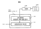
- the transmission beamformer 104 includes a waveform selection unit 130 and a transmission waveform formation / generation unit 131 as shown in FIG.
- the waveform selection unit 130 sets the waveform type corresponding to the values of the parameters (transmission frequency, wave number, transmission focus position, amplitude, etc.) received from the user by the user interface 109, delay time setting for each channel, amplitude modulation, weighting, etc. Select from a predetermined range.
- the transmission waveform generation / generation unit 131 generates a transmission waveform (transmission signal) for each channel using the value selected by the waveform selection unit 130 and passes it to the transmission / reception switching unit 101.
- a transmission signal having a delay time adjusted to the transmission focus for each channel is output from the transmission beam former 104, and the ultrasound probe 100 is transmitted via the transmission / reception switching unit 101. It is sent to the electroacoustic transducer that constitutes each channel.
- Each electroacoustic transducer converts a transmission signal into a sound wave.
- a sound wave transmission pulses
- a sound field ultrasonic beam or transmission beam
- the echo signal of the ultrasonic beam (transmission beam) reflected from the imaging target 120 is received by each electroacoustic transducer of the probe 100 and converted into an electrical signal (reception signal).
- the reception signal of each electroacoustic transducer is transferred to the reception beamformer 105 via the transmission / reception switching unit 101.
- the reception beam former 105 delays the received echo signal to form a reception beam.
- a signal obtained from the reception beam is transferred to the signal processing unit 107.
- the signal processing unit 107 includes a filter processing unit 132, an arithmetic processing unit 133, and a memory 134.
- the signal processing unit 107 performs amplification processing, predetermined filtering processing, and signal calculation processing on the signal obtained from the reception beam under the control of the control unit 106.
- the amplification process is performed according to a TGC (time gain compensation), amplification factor, or the like set by the user via the user interface 109. If necessary, it is temporarily stored in the memory 134.
- the output from the signal processing unit 107 is transferred to the image processing unit 108, and image data and time series data are constructed. Image data and time-series data are output to the display unit 110 and displayed.
- control unit 106 The series of operations of these units is controlled by the control unit 106. Thereby, the control part 106 implement
- THI tissue harmonic imaging
- the user interface 109 receives an operation instruction for the entire apparatus, imaging method selection, parameters necessary for imaging, and the like from the user.
- ultrasound probe 100 of the ultrasound diagnostic apparatus can be mounted as a main body in a separate housing from the ultrasound probe 100, or a part of the probe can be mounted. It is also possible to arrange it inside 100.
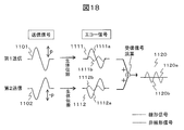
- FIG. 18 is an explanatory diagram of the PI method.
- the echo signal 1111 obtained by the transmission signal 1101 of the first transmission is received in a state where the linear component 1111a and the nonlinear component 1111b generated during biological propagation are mixed.
- the waveform of the transmission signal 1102 of the second transmission is 180 degrees out of phase with the waveform of the transmission signal 1101 of the first transmission, and the linear component 1112a included in the obtained echo signal 1112 is also 1111a. Inverted form.
- the addition calculation of the first and second echo signals becomes the post-computation echo signal 1120, and the linear component of the post-computation echo signal 1120 Since the component of 1120a is 0, only the nonlinear component 1120b can be obtained.
- the amplitude of the waveform of the transmission signal 1202 of the second transmission is 1 / n (n> 1) of the amplitude of the transmission signal 1201 of the first transmission. Modulate.
- the echo signal 1212 obtained by the second transmission has a linear component having a sound pressure of 1 / n and a nonlinear component having a sound pressure of 1 / n 2 with respect to the echo signal 1211 of the first transmission. Accordingly, by performing an operation such as multiplying the echo signal 1212 of the second transmission by n and subtracting it from the echo signal 1211 of the first transmission, it becomes the post-computation echo signal 1220 and the fundamental wave component 1220a becomes 0. Only 1220b remains.
- the PI method it is necessary to accurately invert the phase of the second transmission pulse by 180 degrees with respect to the first transmission pulse, and in the amplitude modulation method, it is necessary to accurately modulate the amplitude of the second transmission pulse. That is, it is necessary to form an accurate waveform of the second transmission pulse.
- the non-linearity of the electroacoustic transducer or the nonlinearity of the transmitter circuit is large, even if the signal waveform input to the electroacoustic transducer is accurately inverted or the amplitude is modulated, linear response is possible.
- the echo signal is mixed with a signal due to the influence of nonlinearity of the electroacoustic transducer, and only the nonlinear component generated by the biological propagation of the imaging target 120 cannot be extracted.
- the entire transmission beam is changed. Adjust the sound pressure (amplitude) and perform the amplitude modulation method. That is, at the time of transmission of the second transmission beam, the sound pressure of the transmission beam is reduced by reducing the drive area on the ultrasonic transmission / reception surface (opening) compared to the transmission of the first transmission beam. This is because the transmitted sound pressure is proportional to the drive area in the ultrasonic transmission / reception surface (opening).
- the waveform of the transmission signal input to the electroacoustic transducer driven in both the first transmission and the second transmission is the same.
- the waveform of the transmission signal supplied is the same when the first and second transmission beams are transmitted. Pulses that are not received can be transmitted, and the sound pressure of the transmission beam can be reduced.
- a channel that is configured by a plurality of electroacoustic transducers and that is driven at the time of transmission of the second transmission beam for each channel that is connected to the same signal line and receives the same transmission signal.
- a non-driven channel non-driven channel
- a transmission signal having the same waveform as that of the first transmission signal is input to the electroacoustic transducer of the drive channel during the second transmission.
- No transmission signal is input to the non-driving channel at the second transmission (the signal voltage is set to 0).
- a desired ratio of channels can be selected to obtain a transmission beam having a desired sound pressure.
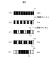
- FIGS. 3A to 3E show an example of the channel arrangement in the opening at the time of transmission and an example of selection of the drive channel at the time of the second transmission.
- the channels 31 composed of 12 channels are arranged in a line in the direction of the transmission aperture (major axis).
- the number of channels in the minor axis direction of the opening during transmission is one.
- Each channel 31 includes a plurality of electroacoustic transducers arranged.
- a gap is provided between adjacent channels 31 for easy understanding. However, in the actual ultrasonic probe 100, between adjacent channels 31. In some cases, there is no gap.
- FIG. 3A shows a drive channel at the time of transmission of the first transmission beam, and all the channels 31 in the opening at the time of transmission are driven.
- FIGS. 3B to 3E show drive channels at the time of transmission of the second transmission beam
- FIGS. 3B, 3C, and 3E show the number of drive channels at the time of transmission of the first time. This is a selection example in which half is a drive channel.
- drive channels 31a and non-drive channels 31b are alternately arranged every other channel
- FIG. 3C shows drive channels 31a and non-drive channels 31b alternately arranged every two channels.
- the drive channel 31a is continuously arranged near the center of the opening at the time of transmission, and the non-drive channel 31b is arranged on both sides.
- the second transmission beam is used if the driving area is half of the entire transmission opening. Can be reduced to half of the first transmission beam.
- FIG. 3D shows an example in which 2/3 of the number of drive channels at the first transmission is used as a drive channel, and one non-drive channel is arranged for every three channels.
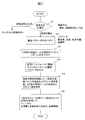
- the control unit 106 reads and executes a program stored in advance in a built-in memory, thereby controlling each unit as shown in the flowchart of FIG. 4 to execute imaging.
- the control unit 106 displays a screen that prompts the user to select an imaging method on the display unit 110, and accepts the user's selection of an imaging method via the user interface 109 (step 41).
- the imaging method it is displayed that the amplitude modulation method, PI method, and normal imaging method that is not THI can be selected, and the user's selection can be accepted.
- the control unit 106 proceeds to step 42 to display a screen for accepting imaging parameters on the display unit 110 via the user interface 109.
- An input of imaging parameters is received from the user.
- imaging parameters the transmission pulse frequency, wave number, focal position, amplitude, and TGC and gain at the time of processing the received signal are received.
- the transmission beam amplitude is also accepted as to whether the amplitude of the second transmission beam is 1 / n times the first amplitude (n> 1). Note that all of these imaging parameters do not need to be selected by the user, and the controller 106 can select parameters prepared in advance according to the imaging method.
- step 41 If the user selects an imaging method other than the amplitude modulation method in step 41, the process proceeds to a step (not shown) for executing the imaging method.
- step 43 the display unit 110 displays what can be selected as the drive channel pattern of the ultrasonic probe 100 at the time of transmitting the second transmission beam.
- a selection is accepted from the user via 109.
- a plurality of types of drive channel patterns as shown in FIGS. 3B to 3E are stored in advance in the memory built in the control unit 106, and 2 received from the user in step 42.
- One or more drive channel patterns corresponding to the amplitude of the transmission beam for the second time are displayed on the display unit 110. For example, if the user sets the amplitude of the second transmission beam to 1 ⁇ 2 times (50%) the amplitude of the first transmission beam and inputs in step 42, the control unit 106 displays the information shown in FIG.
- the patterns (C) and (E) are displayed on the display unit 110.
- the pattern shown in FIG. 3D is displayed on the display unit 110. If the user selects from a plurality of displayed drive channel patterns, or if the user confirms the displayed drive channel pattern, the process proceeds to step 44.
- step 43 the user can select only one pattern in advance according to the amplitude of the second transmission beam, and the control unit 106 can select the pattern instead of selecting from a plurality of patterns. It is.
- the control unit 106 drives the imaging beam (transmission frequency, wave number, transmission focal position, amplitude, etc.) received in step 42 to the transmission beam former 104 and the second transmission beam selected in step 43. Pass the channel pattern.
- the transmission beam former 104 generates a transmission signal for the first transmission beam. That is, the waveform selection unit 130 selects a waveform type corresponding to the imaging parameter, a delay time, an amplitude, a weighting, and the like for each channel from predetermined ranges, and the transmission waveform formation / generation unit 131 A transmission waveform (transmission signal) is generated for each channel with the value selected by the selection unit 130.
- step 45 the control unit 106 switches the transmission / reception switching unit 101 and transfers the first transmission signal to the electroacoustic transducers constituting the respective channels of the transmission opening of the ultrasonic probe 100.
- the transmission signal for the first transmission beam is transferred to the electroacoustic transducers of all the channels 31 in the transmission opening portion of the ultrasonic probe 100 as shown in FIG. Thereby, an ultrasonic beam (transmission beam) having a predetermined amplitude is transmitted to the imaging target 120.
- the echo signal from the living body of the imaging target 120 is received by the electroacoustic transducer in the opening when the ultrasonic probe 100 is received, and converted into an electrical signal.
- the control unit 106 switches the transmission / reception switching unit 101 and passes the reception signal to the reception beamformer 105.
- the reception beamformer 105 delays the received echo signal, forms a reception beam signal, and passes it to the signal processing unit 107.
- the signal processing unit 107 temporarily stores the received beam signal in the memory. Note that the opening at the time of reception does not necessarily coincide with the opening at the time of transmission.
- the transmission beam former 104 generates a transmission signal for the second transmission beam.
- the waveform of the second transmission signal is the same as the first transmission signal waveform for the drive channel 31 a of the drive channel pattern selected in step 44.
- a transmission signal is not generated or a signal having a voltage of zero is generated.
- the control unit 106 switches the transmission / reception switching unit 101 and transfers the transmission signal for the second transmission beam from the transmission beam former 104 to the ultrasound probe 100.
- the ultrasonic probe 100 transmits the second transmission beam only from the drive channel 31a.
- the second transmission beam has a sound pressure smaller than that of the first transmission beam, and is not affected by the non-linear response of the electroacoustic transducer, and only the amplitude is modulated with respect to the first transmission beam. It has a waveform.
- the echo signal from the living body of the second transmission beam is received by the electroacoustic transducer in the reception opening portion of the ultrasonic probe 100 as in the first time.
- the control unit 106 switches the transmission / reception switching unit 101 to deliver the reception signal to the reception beam former 105 and deliver the reception beam signal to the signal processing unit 107.
- the opening at the time of reception may be weighted.
- the signal received by the electroacoustic transducer near the both ends of the opening at the time of reception may be the center of the opening. This is sufficiently small with respect to a signal received by a nearby electroacoustic transducer.
- the opening at the time of the first reception may be different from the opening at the time of the second reception. This is because in imaging, the effect of different openings at the time of reception is small, and is substantially the same when the openings are the same.
- step 46 the control unit 106 performs arithmetic processing on the first and second echo signals, and causes the signal processing unit 107 to perform processing for extracting only the non-linear components.
- the signal processing unit 107 amplifies the received signal obtained from the received beam signal and performs a predetermined filter process, and then multiplies the received signal of the second echo signal by n to obtain the received signal of the first echo signal. Perform the subtraction process.
- the sound pressure level of the linear component is represented by P proportional to p
- the sound pressure level of the non-linear component is proportional to P 2
- the sound pressure of the entire echo signal can be expressed as P + ⁇ P 2 ( ⁇ is an arbitrary number).
- the driving area occupied by the driving channel 31a at the time of transmission of the second transmission beam in the transmission opening is 2/3 as shown in FIG. 3D
- the sound pressure of the second transmission beam is transmitted. is (2/3) p
- the sound pressure of the echo signal is represented as (2/3) P + ⁇ (4/9 ) P 2.
- the second echo signal may be multiplied by 3/2 and subtracted from the first echo signal.
- the term of P is canceled and only ⁇ (1/3) P 2 remains, so that only the nonlinear component can be extracted.
- the first echo signal is multiplied by 2/3 and the second echo signal is subtracted, only the nonlinear component can be extracted in the same manner.
- the signal processing unit 107 determines that the amplitude of the second transmission beam set by the user in step 42 is 1 / n times the amplitude of the first transmission beam (n> 1), and echoes of the first and second transmission beams.
- the sound pressure signal of the signal is P 1 and P 2
- P 1 -nP 2 or (1 / n) P 1 -P 2 is obtained by calculation.
- the linear component is canceled and only the component proportional to the nonlinear component (1- (1 / n)) P 2 or (1 / n) (1- (1 / n)) P 2 can be left.
- the obtained nonlinear component is transferred to the image processing unit 108, and image data is constructed. Thereby, an image by THI can be obtained.
- the second transmission beam having only a part of the channels as the drive channel 31a is transmitted. It is also possible to change the order of the second transmission and the second transmission.
- the entire area when the area of the channel driven at the time of transmission is the largest is the opening at the time of transmission. That is, for example, even when the number of channels of the probe is 196 in the transmission aperture direction, if the 64 channels are the maximum channel region to be driven, the 64 channel region is an opening for transmission.
- the transmission signals are delivered and driven to the plurality of electroacoustic transducers arranged in the ultrasound probe 100 illustrated in FIG.
- the ultrasonic imaging apparatus includes a signal processing unit 107 that performs transmission, a transmission beam former 104, and a control unit 106 that controls the signal processing unit.
- the control unit 106 transmits the ultrasonic beam twice from the transmission beam former 104 to the same position of the imaging target 120 and causes the signal processing unit 107 to calculate a reception signal obtained at each two transmissions.
- the linear component contained in the signal is canceled and the nonlinear component is extracted.
- one transmission is driven by transmitting a transmission signal from the transmission unit to all the electroacoustic transducers having a predetermined area (transmission opening) among the plurality of electroacoustic transducers.
- the transmission signal is selectively delivered and driven only to a part of the electroacoustic transducers having a predetermined area.
- the input voltage having exactly the same waveform is applied to the electroacoustic transducer of the drive channel in both transmissions. Has been. Therefore, it is possible to accurately extract only the non-linear component generated by propagation in the living body without being affected by the waveform distortion due to the voltage dependence resulting from the non-linearity of the device such as the electroacoustic transducer.
- the channels in the transmission opening are driven during the first transmission, and some of the channels in the transmission opening are used during the second transmission.
- the drive channel is used has been described, it is needless to say that the order of the first transmission and the second transmission can be switched.
- the ultrasonic diagnostic apparatus of the second embodiment transmits the transmission beam twice, and determines the number of drive channels (drive area of the opening during transmission) in one transmission.
- This is an ultrasonic diagnostic apparatus that modulates the sound pressure of a transmission beam by making it smaller (smaller) than that in another transmission and performs THI by the amplitude modulation method.
- the generation of grating lobes is further taken into consideration, the linear component remaining after cancellation is reduced, and an appropriate drive channel pattern that can suppress artifacts (virtual images in an image) can be selected.
- the grating lobe will be described.
- the wavefronts of ultrasonic waves emitted from the arrayed electroacoustic transducers are combined to create a transmission beam.
- the electroacoustic transducer is delayed for each channel so that the phase of the ultrasonic wave coincides with the target direction (main axis).
- the transmission pulse emitted from the electroacoustic transducer includes a plurality of waves, it forms a wavefront with one delayed phase of the electroacoustic transducer in adjacent channels. Therefore, a beam is also formed in the direction in which the wavefront is formed, and a strong echo signal is received from a direction different from the main axis.
- a beam having directivity in a direction different from the main axis is called a grating lobe.
- the number of driving channels (driving area in the transmission opening) of the ultrasonic probe 100 is set to the total number of channels (the total of the transmission opening) during one transmission out of two transmissions. THI is performed by eliminating the nonlinearity of the device.
- the normal ultrasonic probe 100 is designed so that a grating lobe does not occur when the channel pitch d is equal to the frequency of the transmission pulse. Therefore, the drive channel pattern selected to reduce the drive area in the transmission opening. Depending on the case, the pitch d may be increased, and the grating lobe generation condition may be satisfied.
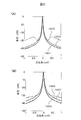
- FIG. 5A shows a simulation result of obtaining a linear component sound field in the vicinity of the focus with a transmission beam depth of 20 mm when a linear array probe is used as the ultrasonic probe 100.
- the ultrasonic transmission / reception surface of the ultrasonic probe 100 has a channel pitch d of 0.2 mm and a total of 42 channels, and the transmission aperture is about 8.4 mm.
- the vertical axis indicates the sound pressure
- the horizontal axis indicates the azimuth angle as a sine function
- 5A is a sound pressure distribution of a linear component of a transmission beam when all channels are driven and a pulse having a center frequency of 9 MHz and a specific bandwidth of 70% is transmitted.
- the specific bandwidth is obtained by dividing the band of the transmission spectrum by the center frequency.
- the plot 1902 uses the drive channel pattern in which the drive channels 31a and the non-drive channels 31b are alternately set as shown in FIG. 3B, and the sound pressure of the transmission beam when the drive area is half that of the drive for all channels. Distribution. However, the plots 1901, 1902 are both normalized by their maximum sound pressures.
- the interval between the drive channels 31a is within the allowable range of the grating lobe. It is necessary to set it accordingly.
- the interval is preferably smaller than two channels.
- the sound pressure distribution of the transmission beam when the drive channel pattern is FIG. 3E and the other conditions are the same as the plot 1902 is the plot 1903 in FIG.
- the drive channel 31a is centered in the transmission opening, and the pitch d between adjacent drive channels does not increase even if the drive area is reduced. No grating lobe is generated. Therefore, the plot 1903 is close to the sound field of the plot 1901.
- the nonlinear signal is extracted by canceling the linear signal in the main axis by the arithmetic processing in step 46 in FIG. 4, the linear signal remaining in the processed signal is smaller than in the case of the plot 1902.
- the grating lobe is set in accordance with the channel pitch d of the mounted ultrasonic probe 100 and the frequency, wave number, focus depth, etc. of the transmission pulse set by the user as the imaging parameter.
- An imaging channel pattern that can be suppressed is obtained in advance by calculation or experiment, and this is stored in advance in a memory in the control unit 106 as a table as shown in FIG.
- the control unit 106 Proceeding to step 83, the optimum drive channel pattern corresponding to the frequency, wave number, and focus depth set as the imaging parameters is read from the table in FIG. 6 in the memory.
- any one of three patterns N, A, and B is selected as the drive channel pattern according to the table of FIG.
- the channel pitch d of the mounted ultrasonic probe 100 may be incorporated in the table as a fixed value when the type of usable ultrasonic probe 100 is fixed. If the user can select and use a plurality of types of ultrasonic probes 100 having different pitches, it is possible to accept an input of pitch d from the user as one of the imaging parameters in step 42. is there. Further, the relationship between the type of ultrasonic probe 100 that can be mounted and the channel pitch d is stored in advance in a memory in the control unit 106 in the form of a table or the like. By selecting the type of the probe 100, the control unit 106 can read out the channel pitch d of the selected ultrasonic probe 100 from the table and use it for selecting the drive channel pattern of the table of FIG. It is.
- the control unit 106 displays the read drive channel pattern and the fact that this pattern is optimal for suppressing the grating lobe on the display unit 110 to indicate to the user. If the user accepts this pattern, go to step 44. In step 83, the user can arbitrarily select a drive channel pattern other than the optimum pattern shown on the display unit 110. In this case, the control unit 106 selects the drive channel pattern. Pattern is used.
- the second embodiment since an optimal drive channel pattern that can suppress the grating lobe can be selected according to the imaging parameter, the cancellation of the linear component due to the grating lobe after processing by the signal processing unit 107 is eliminated. Can be reduced. Therefore, artifacts due to the linear component that remains to be canceled can be suppressed, and a THI image with a higher proportion of nonlinear signals can be obtained.
- CMUT Capacitive micro-machined ultrasonic transducers
- PZT Lead zirconate Titanate
- FIG. 5B shows a simulation result when the specific bandwidth of the transmission pulse is 125% and other conditions are the same as in FIG.
- a plot 1905 is a case where all channels are driven
- a plot 1906 is a case of the drive channel pattern of FIG. 3B
- a plot 1907 is a case of the drive channel pattern of FIG. Comparing the plot 1902 in FIG. 5A and the plot 1906 in FIG. 5B, a drive channel in which the drive channels are alternately set in FIG. 3B by using a broadband pulse having a specific bandwidth of 125%. It can be seen that the grating lobe is suppressed even when the pattern is selected.
- the bandwidth of the transmission pulse may be considered as a parameter for obtaining the optimal drive channel pattern.
- the specific bandwidth corresponds to the wave number in the time domain of the transmission waveform, it is essentially the same even if the wave number of the transmission pulse is used as a parameter.
- the control unit 106 determines the bandwidth of the transmission pulse. Configure to accept from users.
- the horizontal axis of the plot represents the ratio of the area of the drive channel to the total area of the transmission opening
- the vertical axis represents the change in the maximum sound pressure difference of the transmission beam when the drive area is used.
- the maximum sound pressure difference represents the sound pressure difference at the maximum point among the differences from the entire transmission beam when all channels within the transmission aperture are driven. This plot was obtained from the calculation result using the same simulation conditions as the plot 1903 in FIG.
- the smaller the drive area at the time of transmission with a reduced drive area (second transmission) the smaller the sound pressure of the transmitted beam, so that the nonlinear component after the calculation in step 46 in FIG. NHI high THI is possible. For this reason, in order to obtain a large non-linear component, it is desirable that the driving area for the second transmission is small.
- the drive area is set in a range in which the reduction of the remaining linear component and the increase of the nonlinear component can be achieved at the same time.
- the ratio of the driving area is as shown in FIG. In the example, it is desirable to be about 74% or more.
- the drive area of the second transmission is small. Therefore, 74% is selected as the optimum driving area in consideration of both. As a result, it is possible to further reduce the linear component remaining after cancellation while realizing THI having a high S / N ratio.
- the driving area (the number of electroacoustic transducers to be driven is provided by providing the ultrasonic probe 100 with a driving channel and a non-driving channel in one of the two transmissions. )
- the sound pressure of the transmission beam is reduced by providing a driven subchannel and a non-driven subchannel in units of subchannels provided in the channel.
- two or more subchannels 91 are installed in each channel 31.
- the two or more subchannels 91a are driven as shown in FIG. 9B, and the rest are non-driven subchannels. 91b.
- the sound pressure of the transmission beam can be reduced by the ratio of the sub-channel 91a to be driven in the channel 31.
- the pitch of the drive subchannels 91a is always the same as that of the channel 31. It becomes equal to the pitch d.
- the substantial pitch of the channel 31 does not increase, and there is no concern about the occurrence of grating lobes due to the pitch expansion.
- the substantial width of the channel 31 is different by providing the non-driven subchannel 91b, a difference in the sound field due to this slightly occurs.
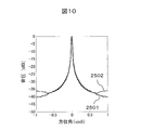
- FIG. 10 is a simulation result of obtaining a linear component sound field in the vicinity of the focus with a transmission beam depth of 20 mm when a linear array probe is used as the ultrasonic probe 100.
- the ultrasonic transmission / reception surface of the ultrasonic probe 100 has a channel pitch d of 0.2 mm and a total of 42 channels, and the transmission aperture is about 8.4 mm.
- the center frequency of the transmission pulse is 9 MHz and the relative bandwidth is 70%.
- a plot 2501 is a sound pressure distribution of a transmission beam when all the subchannels of all the channels 31 are driven, and a plot 2502 shows two subs constituting each channel as shown in FIG. 9B. This is a case where one sub-channel 91a of the channel 91 is driven and the drive area is halved. However, the plots 2501 and 2502 are both normalized by their maximum sound pressures.
- the sound pressure distribution of the transmission beam in the plot 2502 is almost the same as the sound pressure distribution of the transmission beam in the plot 2501, and it can be seen that the generation of grating lobes is suppressed.
- the driving subchannel 91a and the non-driving subchannel 91b in units of subchannels constituting the channel 31, the grating lobe can be suppressed even if the driving area is reduced, and the arc due to the remaining cancellation linear component. Facts can be reduced.
- the switch 2402 is configured to switch so that the transmission signal from the transmission beamformer 104 is transferred to the drive subchannel 91a.
- the switch 2402 is switched by the transmission / reception switching unit 101 under the control of the control unit 106.
- CMUT capacitive transducer
- CMUT electroacoustic transducer
- a DC bias and an AC (alternating current) voltage are applied between the vibrating membrane and two electrodes installed in the lower substrate.
- CMUT if a bias voltage is not applied, the electroacoustic conversion efficiency is extremely poor, and vibration occurs at a frequency twice that of the AC voltage, so that transmission in the band of interest is effectively impossible. Therefore, the ultrasonic probe 100 is connected to a power source 92 that supplies a DC bias to one electrode of each electroacoustic transducer (CMUT).
- the DC bias power source 92 is connected to a DC bias as shown in FIG.
- a control unit 93 that controls the voltage is connected.
- the transmission beam former 104 supplies an AC voltage as a transmission signal for each channel.
- the AC voltage is received only by the CMUT of the subchannel 91a to be driven by the switch 2402, as shown in FIG.
- a DC bias is supplied only to the CMUT of the driven subchannel 91a and a DC bias is not supplied to the non-driven subchannel 91b. It is also possible.
- the DC bias is a constant voltage (common voltage) in the channel to be driven, the same number of DC bias systems 95a and 95b as the number of subchannels arranged in one channel are provided.
- the driving subchannel 91a can be driven by applying a DC bias from the system 95a, and the non-driving subchannel 91b can be driven without applying the DC bias from the system 95b.
- DC bias is supplied from all the systems 95a and 95b.
- a simple configuration in which only two switches are switched can be achieved.
- 11A and 11B show an example in which two subchannels are arranged in one channel, the number of subchannels can be increased to 3 or more, and the driving area can be further reduced. .
- an array type ultrasonic probe 100 such as a linear type or a convex type has an arrangement structure of electroacoustic transducers shaped like a rectangle, and a plurality of channels are arranged in an array shape in the direction of the transmission aperture (long axis).
- the tomographic image to be imaged is drawn in the major axis direction.
- a plurality of channels are arranged in an array in the short axis direction orthogonal to the transmission aperture.
- the focus point of the ultrasonic beam transmission beam
- the short axis direction channel may have a focus point fixed by an acoustic lens or may change the number of drive channels in the short axis direction depending on the depth of the focus point.
- the channel 31a to be driven is selected as follows, one time out of two transmissions.
- the grating lobe can be suppressed when the sound pressure of the transmission beam is reduced by the transmission of. That is, if the pattern of the drive channel 31a in the first column in the short axis direction is set as shown in FIGS. 13B and 13C, the drive channel 31a of the channel in the second and subsequent columns of the short axis is set in one column in the short axis.
- Exclusive to the eye drive channel 31a That is, the channel 31 at a position different from the first row of the short axes is defined as the drive channel 31a.
- the ratio of the area occupied by the drive channels 31a in each column in the minor axis direction may be constant or may be different for each column.
- the drive area of the drive channel pattern of FIG. 13B is 1 ⁇ 2 of the total area of the transmission opening, but when looking in the major axis direction, Since the drive channels 31a in the first and second rows of the short axes are positioned so as to complement the positions of the non-drive channels, the pitch of the drive channels 31a in the major axis direction is the time when all channels in the transmission opening are driven. Is substantially equivalent. Therefore, in the long axis direction, the sound field of the formed transmission beam is equivalent to the sound field due to beam forming when all channels are driven, and generation of grating lobes can be suppressed in the tomographic image to be imaged.
- the drive area of the drive channel pattern in FIG. 13C is 1/3 of the total area of the transmission aperture, but when viewed in the major axis direction, the minor axis first and second columns. Since the drive channels 31a in the third row are in positions that complement each other, in the major axis direction, the pitch of the drive channels 31a is substantially the same as when all the channels in the transmission opening are driven.
- the transmission beam former 104 is arranged two-dimensionally in order to drive the channel 31a as shown in FIGS. 13B and 13C.
- the transmission signals it is possible to configure the transmission signals to be output to all the channels, but it has a configuration to output the transmission signals to the channels for one column along the long axis direction, and via the transmission / reception changeover switch 101, It is also possible to adopt a configuration in which the transmission signal is selectively transferred to any one of the channels in the first, second, and third columns of the short axis. As a result, the drive channel 31a can be driven in a pattern as shown in FIGS. 13B and 13C.
- the channel pattern in which the drive channels in each short axis complement each other has been described.
- the channels in the short axis array may be driven any number of times.
- the pitch of the drive channel 31a is substantially the same as that when all the channels in the transmission opening are driven, so that the generation of grating lobes can be suppressed.
- the drive channel pattern shown in FIG. 13B or the drive channel pattern shown in FIG. 13C is repeatedly arranged. It is also possible to do.
- the drive channel pattern in FIG. 13 (B) is repeatedly arranged twice in the minor axis direction. Can be a pattern.
- the drive channel pattern shown in FIG. 13C can be a pattern that is arranged twice. Further, the drive channel pattern shown in FIG. 13B and the drive channel pattern shown in FIG.
- FIGS. 13B and 13C may be alternately and repeatedly arranged in the minor axis direction. Also in these cases, the effect of suppressing the generation of grating lobes can be obtained as in FIGS. 13B and 13C. In this way, by repeatedly arranging the patterns of FIG. 13B and FIG. 13C, the generation of grating lobes can be suppressed even in a two-dimensional array ultrasonic probe having no distinction between major and minor axes. Therefore, it is effective when tomographic images in a plurality of directions using a two-dimensional array ultrasonic probe that does not distinguish between the long axis and the short axis.
- the configuration other than the channel pattern used for transmission that reduces the drive area is the same as that in the first embodiment, and thus the description thereof is omitted. Note that this embodiment can be combined with the method of reducing the drive area in units of subchannels using the subchannel drive method shown in the third embodiment.
- a configuration in which the frequency of the echo signal is selected by the filter processing unit 132 of the signal processing unit 107 will be described as yet another mode for avoiding the grating lobe. That is, a filter is obtained so as to acquire only a nonlinear signal in a low frequency region, and a grating lobe is avoided.
- the nonlinear signal generated during the propagation through the living body is not limited to the second harmonic component 3115 centered on 2 f 0 . It is known that a non-linear component (difference sound component) 3110 in a low frequency region centering on f s , 2f s and the like is generated.
- the grating lobe generation condition is 0 ⁇ ( ⁇ // where d is the substantial channel pitch and ⁇ is the wavelength of the ultrasonic wave.
- ⁇ ⁇
- ⁇ c / f
- c the speed of sound
- f the frequency. That is, as shown in FIG. 14, the frequency region where the grating lobe 3120 is generated is f> c / d.
- the generated grating lobe component appears in a frequency region of 3.9 MHz or higher. It will be.
- the grating lobe 3120 is removed using this property. That is, in step 46 of FIG. 4, when the filter processing unit 132 of the signal processing unit 107 cuts the high frequency by applying the reception filter, the high-frequency cutoff value is determined from the lower limit c / d of the frequency region of the grating lobe component. Set below and remove. Thereby, the linear signal by the grating lobe 3120 can be prevented from remaining in the received signal, and the non-linear signal of the difference sound component 3110 generated in the low frequency region can be extracted.
- the grating lobe generation condition can be in a wide range. Therefore, the substantial channel pitch d is obtained from the physical channel pitch of the probe 100 and the drive channel pattern, and the high frequency cut-off frequency of the reception filter band is determined from the obtained d and the grating lobe generation condition.
- the filter processing unit 132 of the signal processing unit 107 filters the signal with the reception filter set to a lower frequency than 3.9 MHz, and the difference sound component 3110 The non-linear signal is extracted.
- the grating lobe can be removed by filtering and a nonlinear signal (difference sound component) can be extracted, a THI image using a difference sound component in which artifacts due to the grating lobe are suppressed can be obtained.
- the second to third embodiments and the filter processing of the present embodiment can be combined.
- the drive region (drive channel) having a smaller area than that during one transmission is driven.
- the sum of the overlapping drive areas (drive channels) in the transmission opening at the time of the 2nd to kth transmissions coincides with the drive area (all channels in the transmission opening) at the time of the first transmission.
- a drive region (drive channel) at the time of 2nd to k-th transmission is determined. That is, the drive channels for the 2nd to kth transmissions are mutually exclusive.
- the linear component in the echo signal of the transmission ultrasonic wave is generated in proportion to the sound pressure of the transmission beam.
- the linear signal in the echo signals of the second to kth transmissions having a driving area of 1 / n times (n> 1) with respect to the driving area at the time of the first transmission is a linear signal in the echo signal of the first transmission. 1 / n times (n> 1).
- the 2nd to kth transmission ultrasonic beams transmission beams
- the sum of the linear components of the sound field completely matches the linear component of the sound field of the transmission beam of the first transmission.
- the linear component in the received signal is completely canceled out.
- the grating glove is also a linear component, it is completely removed.
- the nonlinear component mainly including the harmonic component generated while the ultrasonic wave propagates through the living body is generated in proportion to the square of the sound pressure of the transmission beam. Therefore, the non-linear signal in the echo signals of the 2nd to kth transmissions having a driving area of 1 / n times (n> 1) with respect to the driving area at the time of the first transmission is multiplied by 1 / n 2 and 1 Less than / n. That is, since the ratio of the nonlinear signal included in the obtained echo signal is smaller than that of the linear signal, the nonlinear signal remains even if the echo signals of the second to kth transmissions are subtracted from the echo signal of the first transmission. Therefore, the nonlinear component can be extracted by the amplitude modulation method.
- the same imaging method and imaging parameters as those in steps 41 and 42 in FIG. 4 of the first embodiment are received from the user.
- the input of the transmission count k is received together with other parameters.
- step 153 reads out the drive channel pattern corresponding to the set transmission count k from the memory, displays it on the display unit 110, and displays it to the user. The user is prompted to select a desired pattern from the drive channel patterns. If the user selects a pattern via the user interface 109, the control unit 106 accepts this and proceeds to step 44.
- step 44 as in the first embodiment, the imaging channel pattern and imaging parameters are output to the transmission beamformer 104 by the control unit 106.
- the control unit drives the drive channel 31a of the set imaging channel pattern, transmits the first to kth transmission beams, and receives the echo signal each time.
- the received signal is stored in the memory 134 after the signal processing unit 107 performs filter processing or the like. Note that the openings used for each transmission and reception are handled in the same manner as in the first embodiment.
- step 156 the signal processing unit calculates P1- (P2 + P3... + Pk) using the first echo signal (reception signal) P1 to the kth echo signal (reception signal) Pk.
- the linear component is canceled and the nonlinear component is extracted.
- the image processing unit 108 performs image construction and the like.
- FIG. 16A shows a pattern in which the driving channel patterns of the second to third transmissions are exclusively arranged at every other channel.
- FIGS. 16B and 16C show patterns in which drive channels are exclusively arranged every two channels and every three channels, respectively.
- FIG. 16D shows a case where the device having the subchannel structure described in the third embodiment is used, in which two subchannels are arranged in the channel, and the first subchannel is driven as the subchannel in the second transmission. In this pattern, the second subchannel is driven as the drive subchannel 91a in the third transmission. Further, in FIG.
- FIG. 16E shows a pattern in which, in the second transmission, a plurality of channels in the outer region of the transmission opening is the drive channel 31a, and in the third transmission, a plurality of channels in the central region of the transmission opening is the drive channel 31a.
- FIGS. 17A to 17C show patterns for driving two channels at a time in the second to fifth transmissions.
- FIG. 17A shows a pattern in which two adjacent channels are set as drive channels 31a and the positions thereof are shifted for each transmission.
- FIG. 17B drives two channels positioned on both sides of the channel array. In this pattern, the channel 31a is selected, and the inner channel is sequentially selected for each transmission.
- FIG. 17C shows a pattern in which two channels sandwiching three channels are used as drive channels 31a, and the positions of the channels are shifted for each transmission while maintaining an interval between the two drive channels 31a.
- FIG. 17D shows a pattern in which the number and position of channels to be driven are random.
- the nonlinear signal amount of the echo signal P1 of the first transmission is ⁇ P 2 as the nonlinear signal amount that can be extracted by the calculation of the received echo signal
- the driving area of each of the second to Nth transmissions is 1 / (N ⁇ 1) Expressed as double.
- the sound pressure of the echo signal in the first transmission is P
- the echo signal in each of the second to Nth transmissions can be described as (1 / (N ⁇ 1) ) P + ⁇ (1 / (N ⁇ 1) 2 ) P 2
- the sum of echo signals of the 2nd to Nth transmissions is multiplied by (N ⁇ 1) to obtain P + ⁇ (1 / (N-1)) is expressed as P 2.
- transmission / reception is preferably performed three times. In the case of transmission / reception three times, if the areas of the drive channels for the second transmission and the third transmission are made equal, the nonlinear signal obtained after the calculation increases.
- the driving channel pattern for the 2nd to kth transmissions is a pattern in which the nonlinear signal amount is as small as possible. That is, the array pattern for dispersing the sound sources is good, and the array pattern of the drive channels in the transmission openings of the second to kth transmissions should be unbiased.
- the patterns listed in FIGS. 16A and 16D are desirable because these conditions are satisfied.
- the arrangement of the drive channels in the second transmission and the third transmission is biased. Therefore, the nonlinear signals of the second to kth transmissions are larger than the other patterns, and the nonlinearity obtained after the calculation is obtained. The signal amount is reduced.
- This embodiment uses the method of changing the drive area by subchannel driving shown in the third embodiment, and combines the reduction of the drive area in units of subchannels and the reduction of the drive area in units of channels. It is also possible to combine drive patterns to be performed. It is also possible to combine the channel in the minor axis direction shown in the fourth embodiment with the drive array pattern.
- all channels in the transmission opening are driven by the first transmission, and some channels in the transmission opening are driven by the second to kth transmissions, but all the channels are driven.
- the transmission to be performed can be performed by any number of transmissions of the first to kth transmissions. In this case, transmission with driving some channels is performed in the remaining transmissions.
- transmission for driving all channels in the opening during transmission can be performed in a plurality of times.
- the first transmission is performed by driving one-half of all the channels in the opening during transmission
- the second transmission is performed by driving the remaining one-half
- the first transmission and the second transmission are combined to obtain an echo signal similar to that at the time of transmission by driving all channels of the opening at the time of transmission.
- transmission is performed by driving some channels from the remaining third transmission to the (k + 1) th transmission, and by subtracting the obtained echo signal from the sum of the echo signals of the first transmission and the second transmission, Nonlinear components can be extracted.
- the imaging method for performing THI has been described.
- an ultrasound diagnostic apparatus that can selectively execute the imaging methods of the first to sixth embodiments may be used. It is. In that case, it is desirable because the optimum method required can be selected under the actual use conditions.
- the imaging method of the first to fifth embodiments that enables THI by two transmissions is selected, and when high-resolution imaging is required, the sixth implementation is performed. What is necessary is just to comprise so that the imaging method of a form can be adjusted automatically or manually.
Abstract
Description
図1を用いて第1の実施形態の超音波診断装置の全体構成について説明する。図1は、超音波診断装置の概略構成を示すブロック図である。図1のように、本装置は、超音波探触子100と、送受切替部101、送信ビームフォーマ104、受信ビームフォーマ105、制御部106、信号処理部107、画像処理部108、ユーザーインターフェイス109、および、表示部110を備えている。 <First Embodiment>
The overall configuration of the ultrasonic diagnostic apparatus according to the first embodiment will be described with reference to FIG. FIG. 1 is a block diagram showing a schematic configuration of an ultrasonic diagnostic apparatus. As shown in FIG. 1, this apparatus includes an
第2の実施形態の超音波診断装置について説明する。 <Second Embodiment>
An ultrasonic diagnostic apparatus according to the second embodiment will be described.
第3の実施形態の超音波診断装置について説明する。 <Third Embodiment>
An ultrasonic diagnostic apparatus according to the third embodiment will be described.
第4の実施形態では、第2および第3の実施形態で示したグレーティングローブによる打ち消し残り線形成分を抑圧する、さらに別の形態について説明する。 <Fourth Embodiment>
In the fourth embodiment, a description will be given of still another mode in which the cancellation residual linear component due to the grating lobe shown in the second and third embodiments is suppressed.
第5の実施形態では、グレーティングローブを避けるさらに別の形態として、信号処理部107のフィルタ処理部132より、エコー信号の周波数を選択する構成について説明する。すなわち、低周波領域の非線形信号のみを取得するようにフィルタをかけて、グレーティングローブを避ける。 <Fifth Embodiment>
In the fifth embodiment, a configuration in which the frequency of the echo signal is selected by the
第6の実施形態の超音波診断装置について説明する。第2~第5の実施形態では、2回の送受信を行う振幅変調法において、グレーティングローブを抑制し、打ち消し残り線形成分を低減させながらデバイスの非線形性に影響されないTHIを実現する方法について述べた。第6の本実施形態では、3回以上の送受信を行って、グレーティングローブの影響を完全に除外する撮像方法を説明する。 <Sixth Embodiment>
An ultrasonic diagnostic apparatus according to the sixth embodiment will be described. In the second to fifth embodiments, in the amplitude modulation method in which transmission / reception is performed twice, a method for realizing THI that is not affected by the nonlinearity of the device while suppressing the grating lobe and reducing the linear component remaining after cancellation is described. . In the sixth embodiment, an imaging method will be described in which transmission and reception are performed three or more times to completely exclude the influence of the grating lobe.
第1~第6の実施形態は、それぞれTHIを行う撮像方法を説明したが、第1~第6の実施の形態の撮像方法が選択的に実行できる超音波診断装置の構成にすることも可能である。その場合、実際に使用する条件において、必要とされる最適な方法を選択できるため望ましい。 <Seventh Embodiment>
In each of the first to sixth embodiments, the imaging method for performing THI has been described. However, an ultrasound diagnostic apparatus that can selectively execute the imaging methods of the first to sixth embodiments may be used. It is. In that case, it is desirable because the optimum method required can be selected under the actual use conditions.
101 送受切替部
104 送信ビームフォーマ
105 受信ビームフォーマ
106 制御部
107 信号処理部
108 画像処理部
109 ユーザーインターフェイス
110 表示部
120 撮像対象
132 フィルタ処理部
133 演算処理部
134 メモリ
130 波形選択部
131 送信波形形成・発生部
1101 第1送信パルス
1102 第2送信パルス
1111 第1送信のエコー信号
1112 第2送信のエコー信号
1120 演算後のエコー信号
1201 第1送信パルス
1202 第2送信パルス
1211 第1送信のエコー信号
1212 第2送信のエコー信号
1220 演算後のエコー信号 DESCRIPTION OF
Claims (22)
- 複数の電気音響変換素子に送信信号を受け渡して駆動させ、撮像対象の所定位置に超音波ビームを送信させる送信部と、
前記撮像対象からの前記超音波ビームのエコーを前記複数の電気音響変換素子で受信させ、受信信号を得る受信部と、
前記受信信号を演算処理して画像を生成する信号処理部と、
前記送信部と前記信号処理部とを制御する制御部とを有し、
前記制御部は、前記撮像対象の同位置に対して、前記送信部から前記超音波ビームを2回送信させ、該2回の送信のたびに得た前記受信信号を前記信号処理部に演算させ、前記受信信号に含まれる非線形成分を抽出させ、
前記2回の送信のうち、1回の送信は前記複数の電気音響変換素子のうち所定の面積となる電気音響変換素子全てに前記送信部から前記送信信号を受け渡して駆動させ、他の1回の送信は、前記所定の面積となる電気音響変換素子のうちの一部のみに選択的に前記送信信号を受け渡して駆動させることを特徴とする超音波撮像装置。 A transmission unit that delivers and drives transmission signals to a plurality of electroacoustic transducers, and transmits an ultrasonic beam to a predetermined position of an imaging target;
A receiving unit that receives echoes of the ultrasonic beam from the imaging object by the plurality of electroacoustic transducers and obtains a reception signal;
A signal processing unit that performs arithmetic processing on the received signal to generate an image;
A control unit that controls the transmission unit and the signal processing unit;
The control unit causes the ultrasonic beam to be transmitted twice from the transmission unit to the same position of the imaging target, and causes the signal processing unit to calculate the reception signal obtained at each of the two transmissions. , Extracting a nonlinear component contained in the received signal,
Of the two transmissions, one transmission is driven by passing the transmission signal from the transmitter to all the electroacoustic transducers having a predetermined area among the plurality of electroacoustic transducers. Is transmitted by selectively delivering the transmission signal to only a part of the electroacoustic transducer having the predetermined area, and driving the ultrasonic imaging apparatus. - 請求項1に記載の超音波撮像装置において、前記他の1回の送信で、前記一部の電気音響変換素子に受け渡される送信信号の波形は、前記1回の送信でその電気音響変換素子に受け渡される送信信号の波形と同じであることを特徴とする超音波撮像装置。 2. The ultrasonic imaging apparatus according to claim 1, wherein a waveform of a transmission signal delivered to the one part of the electroacoustic transducer in the other one-time transmission is the electroacoustic transducer in the one-time transmission. An ultrasonic imaging apparatus having the same waveform as that of a transmission signal passed to
- 請求項1に記載の超音波撮像装置において、前記受信部は、前記2回の送信の前記超音波ビームのエコーそれぞれを、同一の電気音響変換素子により受信させ、前記受信信号を得ることを特徴とする超音波撮像装置。 2. The ultrasonic imaging apparatus according to claim 1, wherein the reception unit receives the echoes of the ultrasonic beams of the two transmissions by the same electroacoustic transducer to obtain the reception signal. An ultrasonic imaging apparatus.
- 請求項1に記載の超音波撮像装置において、前記複数の電気音響変換素子は、複数のチャンネルに分割された構成であり、前記他の1回の送信では、前記送信信号を受け渡して駆動させる前記電気音響変換素子が、前記チャンネル単位で選択されることを特徴とする超音波撮像装置。 2. The ultrasonic imaging apparatus according to claim 1, wherein the plurality of electroacoustic transducers are configured to be divided into a plurality of channels, and in the other one-time transmission, the transmission signal is delivered and driven. An ultrasonic imaging apparatus, wherein an electroacoustic transducer is selected for each channel.
- 請求項1に記載の超音波撮像装置において、前記制御部は、撮像パラメータに応じて予め定められている前記他の1回の送信で駆動させる電気音響変換素子のパターンに従って、前記送信信号を受け渡す電気音響変換素子を選択することを特徴とする超音波撮像装置。 2. The ultrasonic imaging apparatus according to claim 1, wherein the control unit receives the transmission signal in accordance with a pattern of an electroacoustic transducer that is driven by the other one transmission that is determined in advance according to an imaging parameter. An ultrasonic imaging apparatus, wherein an electroacoustic transducer to be passed is selected.
- 請求項5に記載の超音波撮像装置において、前記制御部は、グレーティングローブを最小にするためのパターンを、前記撮像パラメータに応じて選択することを特徴とする超音波撮像装置。 6. The ultrasonic imaging apparatus according to claim 5, wherein the control unit selects a pattern for minimizing a grating lobe according to the imaging parameter.
- 請求項6に記載の超音波撮像装置において、前記制御部は、グレーティングローブを最小にするために、前記受信信号を所定の周波数領域について取り出すフィルタリング処理を前記撮像パラメータに応じて設定することを特徴とする超音波撮像装置。 7. The ultrasonic imaging apparatus according to claim 6, wherein the control unit sets a filtering process for extracting the received signal for a predetermined frequency region in accordance with the imaging parameter in order to minimize a grating lobe. An ultrasonic imaging apparatus.
- 請求項5に記載の超音波撮像装置において、撮像パラメータの入力を操作者から受け付けるユーザーインターフェイスをさらに有し、前記制御部は、ユーザーインターフェイスが受け付けた撮像パラメータに応じて、前記パターンを選択することを特徴とする超音波撮像装置。 6. The ultrasonic imaging apparatus according to claim 5, further comprising a user interface that receives an input of imaging parameters from an operator, wherein the control unit selects the pattern according to the imaging parameters received by the user interface. An ultrasonic imaging apparatus characterized by the above.
- 請求項1に記載の超音波撮像装置において、前記複数の電気音響変換素子は、複数のチャンネルに分割され、前記チャンネルは、さらに複数のサブチャンネルに分割された構造であり、
前記他の1回の送信では、前記チャンネルごとに、前記複数のサブチャンネルの中から1以上のサブチャンネルが選択され、該サブチャンネル内の前記電気音響変換素子に前記送信信号が受け渡され駆動されることを特徴とする超音波撮像装置。 The ultrasonic imaging apparatus according to claim 1, wherein the plurality of electroacoustic transducers are divided into a plurality of channels, and the channels are further divided into a plurality of subchannels.
In the other one-time transmission, one or more subchannels are selected from the plurality of subchannels for each channel, and the transmission signal is delivered to the electroacoustic transducer in the subchannel and driven. An ultrasonic imaging apparatus. - 請求項1に記載の超音波撮像装置において、前記複数の電気音響変換素子は、静電容量型の電気音響変換素子であり、前記電気音響変換素子には、直流バイアス電圧と、前記送信部から前記送信信号として供給される交流電圧信号とが印加され、
前記制御部は、前記他の1回の送信で、前記所定の面積となる電気音響変換素子のうちの一部のみに選択的に前記送信信号を受け渡す電気音響変換素子に対しては前記直流バイアス電圧を供給し、それ以外の電気音響素子に対しては前記直流バイアス電圧を供給しないことを特徴とする超音波撮像装置。 The ultrasonic imaging apparatus according to claim 1, wherein the plurality of electroacoustic transducers are electrostatic capacitance type electroacoustic transducers, and the electroacoustic transducers include a DC bias voltage and a transmitter. AC voltage signal supplied as the transmission signal is applied,
The controller is configured to transmit the transmission signal selectively to only a part of the electroacoustic transducers having the predetermined area in the other one-time transmission. An ultrasonic imaging apparatus, wherein a bias voltage is supplied and the DC bias voltage is not supplied to other electroacoustic elements. - 請求項4に記載の超音波撮像装置において、前記チャンネルは、所定の長軸方向と短軸方向の2次元に配列され、前記長軸に沿った各列で駆動されるチャンネルは、列同士で排他的な位置に配置されることを特徴とする超音波撮像装置。 5. The ultrasonic imaging apparatus according to claim 4, wherein the channels are two-dimensionally arranged in a predetermined major axis direction and a minor axis direction, and the channels driven in each column along the major axis are columns. An ultrasonic imaging apparatus characterized by being arranged at an exclusive position.
- 請求項4に記載の超音波撮像装置において、前記信号処理部は、受信信号を所定の周波数帯域で取り出すフィルタリング処理を行い、
前記所定の周波数帯域は、駆動される複数のチャンネルの間隔をd、撮像対象内の音速をcとしたとき、c/d以下の周波数帯域であることを特徴とする超音波撮像装置。 The ultrasonic imaging apparatus according to claim 4, wherein the signal processing unit performs a filtering process for extracting a received signal in a predetermined frequency band,
The ultrasonic imaging apparatus according to claim 1, wherein the predetermined frequency band is a frequency band equal to or less than c / d, where d is an interval between a plurality of driven channels and c is a speed of sound within the imaging target. - 請求項4に記載の超音波撮像装置において、前記他の1回の送信では、前記制御部は、隣り合うチャンネルを連続させて前記送信信号を受け渡すことを特徴とする超音波撮像装置。 5. The ultrasonic imaging apparatus according to claim 4, wherein, in the other one-time transmission, the control unit passes the transmission signal continuously in adjacent channels.
- 所定の超音波送受面に配列された複数の電気音響変換素子に送信信号を受け渡して駆動させ、撮像対象の所定位置に超音波ビームを送信させる送信部と、
前記撮像対象からの前記超音波ビームのエコーを前記複数の電気音響変換素子で受信させ、受信信号を得る受信部と、
前記受信信号を演算処理して画像を生成する信号処理部と、
前記送信部と前記信号処理部とを制御する制御部とを有し、
前記制御部は、前記撮像対象の同位置に対して、前記送信部から振幅の異なる前記超音波ビームを2回以上送信させ、該2回以上の送信のたびに得た前記受信信号を前記信号処理部に演算させ、前記受信信号に含まれる非線形成分を抽出させ、
前記2回以上の送信には、前記超音波送受面の全ての電気音響変換素子を駆動させる送信と、前記超音波送受面のうち一部領域の前記電気音響変換素子のみを駆動させる送信とが含まれることを特徴とする超音波撮像装置。 A transmission unit that transmits and transmits a transmission signal to a plurality of electroacoustic transducers arranged on a predetermined ultrasonic transmission / reception surface, and transmits an ultrasonic beam to a predetermined position of an imaging target;
A receiving unit that receives echoes of the ultrasonic beam from the imaging object by the plurality of electroacoustic transducers and obtains a reception signal;
A signal processing unit that performs arithmetic processing on the received signal to generate an image;
A control unit that controls the transmission unit and the signal processing unit;
The control unit transmits the ultrasonic beam having different amplitudes from the transmission unit to the same position of the imaging target two or more times, and the received signal obtained at each of the two or more transmissions is the signal. Let the processing unit calculate, extract non-linear components contained in the received signal,
The two or more transmissions include transmission for driving all the electroacoustic transducers on the ultrasonic transmission / reception surface and transmission for driving only the electroacoustic transducers in a partial area of the ultrasonic transmission / reception surface. An ultrasonic imaging apparatus characterized by being included. - 複数の電気音響変換素子に送信信号を受け渡して駆動させ、撮像対象の所定位置に超音波ビームを送信させる送信部と、
前記撮像対象からの前記超音波ビームのエコーを前記複数の電気音響変換素子で受信させ、受信信号を得る受信部と、
前記受信信号を演算処理して画像を生成する信号処理部と、
前記送信部と前記信号処理部とを制御する制御部とを有し、
前記制御部は、前記撮像対象の同位置に対して、前記送信部から前記超音波ビームを3回以上送信させ、該3回以上の送信のたびに得た前記受信信号を前記信号処理部に演算させ、前記受信信号に含まれる非線形成分を抽出させ、
前記3回以上の送信のうち、1回の送信は前記複数の電気音響変換素子のうち所定の面積となる電気音響変換素子全てに前記送信部から前記送信信号を受け渡して駆動させ、残りの2回以上の送信は、前記所定の面積となる電気音響変換素子のうちの一部のみに選択的に前記送信信号を受け渡して駆動させ、
前記残りの2回以上の送信で選択される前記一部の電気音響変換素子は、前記所定の面積となる複数の電気音響変換素子から、各送信間で排他的に選択されることを特徴とする超音波撮像装置。 A transmission unit that delivers and drives transmission signals to a plurality of electroacoustic transducers, and transmits an ultrasonic beam to a predetermined position of an imaging target;
A receiving unit that receives echoes of the ultrasonic beam from the imaging object by the plurality of electroacoustic transducers and obtains a reception signal;
A signal processing unit that performs arithmetic processing on the received signal to generate an image;
A control unit that controls the transmission unit and the signal processing unit;
The control unit causes the transmission unit to transmit the ultrasonic beam three or more times to the same position of the imaging target, and the received signal obtained at each of the three or more transmissions to the signal processing unit. Calculating, extracting a nonlinear component contained in the received signal,
Of the three or more transmissions, one transmission is driven by passing the transmission signal from the transmitter to all the electroacoustic transducers having a predetermined area among the plurality of electroacoustic transducers, and the remaining two More than once transmission, selectively transmit and transmit the transmission signal only to a part of the electroacoustic transducer having the predetermined area,
The part of the electroacoustic transducers selected in the remaining two or more transmissions are exclusively selected between the transmissions from the plurality of electroacoustic transducers having the predetermined area. An ultrasonic imaging apparatus. - 請求項15に記載の超音波撮像装置において、前記信号処理部は、前記1回の送信で得た受信信号から、前記残りの2回以上の送信で得た受信信号をすべて差し引くことにより、前記受信信号に含まれる非線形成分を抽出することを特徴とする超音波撮像装置。 The ultrasonic imaging apparatus according to claim 15, wherein the signal processing unit subtracts all the received signals obtained by the remaining two or more transmissions from the received signal obtained by the one transmission. An ultrasonic imaging apparatus characterized by extracting a non-linear component contained in a received signal.
- 請求項15に記載の超音波撮像装置において、前記残りの2回以上の送信により、前記所定の面積となる複数の電気音響変換素子の全てが1回ずつ駆動されることを特徴とする超音波撮像装置。 16. The ultrasonic imaging apparatus according to claim 15, wherein all of the plurality of electroacoustic transducers having the predetermined area are driven once by the remaining two or more transmissions. Imaging device.
- 請求項15に記載の超音波撮像装置において、前記残りの2回以上の送信ごとに、前記制御部は、前記送信信号を受け渡して駆動させる前記電気音響変換素子の面積が、それぞれ一定となるように、前記送信信号を受け渡して駆動させる前記電気音響変換素子を選択することを特徴とする超音波撮像装置。 16. The ultrasonic imaging apparatus according to claim 15, wherein each time the remaining two or more transmissions are performed, the control unit delivers and transmits the transmission signal so that the area of the electroacoustic conversion element is constant. And selecting the electroacoustic transducer to be driven by delivering the transmission signal.
- 請求項15に記載の超音波撮像装置において、前記複数の電気音響変換素子は、複数のチャンネルに分割された構成であり、
前記残りの2回以上の送信では、前記送信信号を受け渡して駆動させる前記電気音響変換素子が、前記チャンネル単位で選択されることを特徴とする超音波撮像装置。 The ultrasonic imaging apparatus according to claim 15, wherein the plurality of electroacoustic transducers are configured to be divided into a plurality of channels.
In the remaining two or more transmissions, the electroacoustic transducer that delivers and drives the transmission signal is selected in units of channels. - 請求項15に記載の超音波撮像装置において、前記複数の電気音響変換素子は、複数のチャンネルに分割され、前記チャンネルは、さらに複数のサブチャンネルに分割された構造であり、
前記残りの2回以上の送信では、前記送信信号を受け渡して駆動させる前記電気音響変換素子が、前記サブチャンネル単位で選択されることを特徴とする超音波撮像装置。 The ultrasonic imaging apparatus according to claim 15, wherein the plurality of electroacoustic transducers are divided into a plurality of channels, and the channels are further divided into a plurality of subchannels.
In the remaining two or more transmissions, the electroacoustic transducer for delivering and driving the transmission signal is selected in units of subchannels. - 請求項19に記載の超音波撮像装置において、前記制御部は、前記残りの2回以上の送信で、送信信号を受け渡して駆動させるチャンネルと、前記送信信号を受け渡さないチャンネルとを少なくとも1チャンネルごと交互に選択することを特徴とする超音波撮像装置。 21. The ultrasonic imaging apparatus according to claim 19, wherein the control unit includes at least one channel for delivering and driving a transmission signal in the remaining two or more transmissions and a channel not delivering the transmission signal. An ultrasonic imaging apparatus that alternately selects each image.
- 請求項20に記載の超音波撮像装置において、前記残りの2回以上の送信では、前記チャンネルごとに、前記複数のサブチャンネルの中から送信信号を受け渡して駆動させるサブチャンネルと、前記送信信号を受け渡さないサブチャンネルが少なくとも1サブチャンネルごと交互に選択されることを特徴とする超音波撮像装置。 The ultrasonic imaging apparatus according to claim 20, wherein in the remaining two or more transmissions, for each channel, a subchannel that delivers and drives a transmission signal from the plurality of subchannels, and the transmission signal is transmitted. An ultrasonic imaging apparatus, wherein sub-channels that are not delivered are alternately selected for at least one sub-channel.
Priority Applications (4)
| Application Number | Priority Date | Filing Date | Title |
|---|---|---|---|
| JP2013510902A JP5829680B2 (en) | 2011-04-20 | 2012-01-20 | Ultrasonic imaging device |
| EP12773866.4A EP2700363A4 (en) | 2011-04-20 | 2012-01-20 | Ultrasound imaging apparatus |
| CN201280006196.4A CN103327903B (en) | 2011-04-20 | 2012-01-20 | Ultrasonic imaging apparatus |
| US13/985,122 US9642596B2 (en) | 2011-04-20 | 2012-01-20 | Ultrasound imaging apparatus |
Applications Claiming Priority (2)
| Application Number | Priority Date | Filing Date | Title |
|---|---|---|---|
| JP2011-094418 | 2011-04-20 | ||
| JP2011094418 | 2011-04-20 |
Publications (1)
| Publication Number | Publication Date |
|---|---|
| WO2012144243A1 true WO2012144243A1 (en) | 2012-10-26 |
Family
ID=47041369
Family Applications (1)
| Application Number | Title | Priority Date | Filing Date |
|---|---|---|---|
| PCT/JP2012/051259 WO2012144243A1 (en) | 2011-04-20 | 2012-01-20 | Ultrasound imaging apparatus |
Country Status (5)
| Country | Link |
|---|---|
| US (1) | US9642596B2 (en) |
| EP (1) | EP2700363A4 (en) |
| JP (1) | JP5829680B2 (en) |
| CN (1) | CN103327903B (en) |
| WO (1) | WO2012144243A1 (en) |
Cited By (4)
| Publication number | Priority date | Publication date | Assignee | Title |
|---|---|---|---|---|
| JP2016077510A (en) * | 2014-10-16 | 2016-05-16 | キヤノン株式会社 | Probe and information acquisition apparatus |
| JP2018175373A (en) * | 2017-04-12 | 2018-11-15 | コニカミノルタ株式会社 | Ultrasound diagnostic apparatus and ultrasound probe |
| EP2934333B1 (en) * | 2012-12-21 | 2019-05-15 | Volcano Corporation | Method for multi-frequency imaging using high-bandwidth transducer outputs |
| JP7470167B2 (en) | 2021-10-29 | 2024-04-17 | スーパー ソニック イマジン | Method and system for determining physical properties of a medium - Patents.com |
Families Citing this family (11)
| Publication number | Priority date | Publication date | Assignee | Title |
|---|---|---|---|---|
| JP5924296B2 (en) * | 2013-03-19 | 2016-05-25 | コニカミノルタ株式会社 | Ultrasound diagnostic imaging equipment |
| CN104546005B (en) * | 2015-01-28 | 2017-03-15 | 声泰特(成都)科技有限公司 | A kind of ultrasound non-linear imaging method and system |
| KR102524068B1 (en) * | 2015-02-10 | 2023-04-20 | 삼성전자주식회사 | Ultrasound diagnosis apparatus, ultrasound probe and controlling method of the same |
| JP6542047B2 (en) * | 2015-07-03 | 2019-07-10 | キヤノンメディカルシステムズ株式会社 | Ultrasonic diagnostic equipment |
| KR102560033B1 (en) * | 2015-11-09 | 2023-07-26 | 삼성전자주식회사 | Probe apparatus and the controlling method thereof |
| JP6801469B2 (en) * | 2017-01-20 | 2020-12-16 | コニカミノルタ株式会社 | Ultrasonic diagnostic equipment |
| JP6782649B2 (en) * | 2017-02-28 | 2020-11-11 | 株式会社日立製作所 | Ultrasound imaging device |
| CN107374670A (en) * | 2017-07-20 | 2017-11-24 | 朗昇科技(苏州)有限公司 | A kind of synthetic aperture supersonic imaging device and method |
| EP3658951A1 (en) * | 2017-07-26 | 2020-06-03 | Mayo Foundation for Medical Education and Research | Methods for encoded multi-pulse contrast enhanced ultrasound imaging |
| JP7302163B2 (en) * | 2018-11-22 | 2023-07-04 | コニカミノルタ株式会社 | ULTRASOUND DIAGNOSTIC APPARATUS AND ULTRASOUND IMAGE GENERATING METHOD |
| CN109620291B (en) * | 2019-02-01 | 2021-09-21 | 深圳先进技术研究院 | Ultrasonic signal adjusting method and device and ultrasonic array |
Citations (4)
| Publication number | Priority date | Publication date | Assignee | Title |
|---|---|---|---|---|
| US5577505A (en) | 1996-02-06 | 1996-11-26 | Hewlett-Packard Company | Means for increasing sensitivity in non-linear ultrasound imaging systems |
| US5678553A (en) | 1994-11-01 | 1997-10-21 | Schering Aktiengesellschaft | Ultrasonic processes and circuits for carrying out those processes |
| US6095980A (en) | 1997-10-02 | 2000-08-01 | Sunnybrook Health Science Centre | Pulse inversion doppler ultrasonic diagnostic imaging |
| JP2009018161A (en) * | 2007-07-16 | 2009-01-29 | General Electric Co <Ge> | Method and instrument for multiple transmission contrast enhancement imaging |
Family Cites Families (12)
| Publication number | Priority date | Publication date | Assignee | Title |
|---|---|---|---|---|
| GB2114295B (en) * | 1982-01-29 | 1985-09-04 | Emi Ltd | Improvements in or relating to ultrasonic transducer arrays |
| RU2099698C1 (en) * | 1996-10-17 | 1997-12-20 | Йелстаун Корпорейшн Н.В. | Ultrasonic method measuring characteristics of stressed-deformed state of bolted and studded joints |
| JP3242864B2 (en) | 1997-06-12 | 2001-12-25 | アロカ株式会社 | Ultrasonic diagnostic apparatus and ultrasonic transmitting / receiving method for ultrasonic diagnostic |
| JP4260920B2 (en) | 1998-05-13 | 2009-04-30 | 株式会社東芝 | Ultrasonic diagnostic equipment |
| ITSV20020058A1 (en) * | 2002-11-28 | 2004-05-29 | Esaote Spa | METHOD AND DEVICE FOR THE FORMATION OF BEAMS OF ACOUSTIC WAVES, IN PARTICULAR ULTRASOUND AND IN A SPECIAL WAY FOR |
| US7207942B2 (en) * | 2003-07-25 | 2007-04-24 | Siemens Medical Solutions Usa, Inc. | Adaptive grating lobe suppression in ultrasound imaging |
| US7744532B2 (en) * | 2004-03-31 | 2010-06-29 | Siemens Medical Solutions Usa, Inc. | Coherence factor adaptive ultrasound imaging methods and systems |
| JP4583068B2 (en) | 2004-05-11 | 2010-11-17 | 株式会社東芝 | Ultrasonic diagnostic equipment |
| CN1976635A (en) * | 2004-06-30 | 2007-06-06 | 皇家飞利浦电子股份有限公司 | Non-linear ultrasonic diagnostic imaging using intermodulation component signals |
| JP4790315B2 (en) | 2005-05-31 | 2011-10-12 | オリンパスメディカルシステムズ株式会社 | Capacitive ultrasonic transducer |
| US8465431B2 (en) * | 2005-12-07 | 2013-06-18 | Siemens Medical Solutions Usa, Inc. | Multi-dimensional CMUT array with integrated beamformation |
| US9033888B2 (en) * | 2010-02-08 | 2015-05-19 | Dalhousie University | Ultrasound imaging system using beamforming techniques for phase coherence grating lobe suppression |
-
2012
- 2012-01-20 EP EP12773866.4A patent/EP2700363A4/en not_active Withdrawn
- 2012-01-20 CN CN201280006196.4A patent/CN103327903B/en active Active
- 2012-01-20 JP JP2013510902A patent/JP5829680B2/en active Active
- 2012-01-20 US US13/985,122 patent/US9642596B2/en active Active
- 2012-01-20 WO PCT/JP2012/051259 patent/WO2012144243A1/en active Application Filing
Patent Citations (4)
| Publication number | Priority date | Publication date | Assignee | Title |
|---|---|---|---|---|
| US5678553A (en) | 1994-11-01 | 1997-10-21 | Schering Aktiengesellschaft | Ultrasonic processes and circuits for carrying out those processes |
| US5577505A (en) | 1996-02-06 | 1996-11-26 | Hewlett-Packard Company | Means for increasing sensitivity in non-linear ultrasound imaging systems |
| US6095980A (en) | 1997-10-02 | 2000-08-01 | Sunnybrook Health Science Centre | Pulse inversion doppler ultrasonic diagnostic imaging |
| JP2009018161A (en) * | 2007-07-16 | 2009-01-29 | General Electric Co <Ge> | Method and instrument for multiple transmission contrast enhancement imaging |
Non-Patent Citations (1)
| Title |
|---|
| See also references of EP2700363A4 |
Cited By (4)
| Publication number | Priority date | Publication date | Assignee | Title |
|---|---|---|---|---|
| EP2934333B1 (en) * | 2012-12-21 | 2019-05-15 | Volcano Corporation | Method for multi-frequency imaging using high-bandwidth transducer outputs |
| JP2016077510A (en) * | 2014-10-16 | 2016-05-16 | キヤノン株式会社 | Probe and information acquisition apparatus |
| JP2018175373A (en) * | 2017-04-12 | 2018-11-15 | コニカミノルタ株式会社 | Ultrasound diagnostic apparatus and ultrasound probe |
| JP7470167B2 (en) | 2021-10-29 | 2024-04-17 | スーパー ソニック イマジン | Method and system for determining physical properties of a medium - Patents.com |
Also Published As
| Publication number | Publication date |
|---|---|
| EP2700363A1 (en) | 2014-02-26 |
| CN103327903A (en) | 2013-09-25 |
| CN103327903B (en) | 2015-09-30 |
| JPWO2012144243A1 (en) | 2014-07-28 |
| JP5829680B2 (en) | 2015-12-09 |
| EP2700363A4 (en) | 2014-12-17 |
| US9642596B2 (en) | 2017-05-09 |
| US20130331699A1 (en) | 2013-12-12 |
Similar Documents
| Publication | Publication Date | Title |
|---|---|---|
| JP5829680B2 (en) | Ultrasonic imaging device | |
| JP4551524B2 (en) | Ultrasonic probe and ultrasonic diagnostic apparatus | |
| JP4260920B2 (en) | Ultrasonic diagnostic equipment | |
| US6910380B2 (en) | Ultrasonic transmitting and receiving apparatus | |
| EP2000096B1 (en) | Ultrasound imaging device | |
| JP2002301068A (en) | Ultrasonic diagnostic apparatus | |
| JP2007029745A (en) | Medical diagnostic ultrasound transducer system for harmonics | |
| US20150018688A1 (en) | Ultrasound probe and ultrasound diagnostic apparatus including same | |
| US5081995A (en) | Ultrasonic nondiffracting transducer | |
| JP6344026B2 (en) | Ultrasonic probe and ultrasonic diagnostic imaging apparatus | |
| Ponnle et al. | Suppression of grating lobe artifacts in ultrasound images formed from diverging transmitting beams by modulation of receiving beams | |
| JP4071864B2 (en) | Ultrasonic wave transmitter and ultrasonic imaging device | |
| JP4728466B2 (en) | Method and imaging system for imaging a substance | |
| JP4575014B2 (en) | Ultrasonic diagnostic equipment | |
| JP4393572B2 (en) | Ultrasonic diagnostic equipment | |
| WO2014192466A1 (en) | Ultrasound diagnostic device, method for generating acoustic ray signal of ultrasound diagnostic device, and program for generating acoustic ray signal of ultrasound diagnostic device | |
| JP7080309B2 (en) | Ultrasonic probe, ultrasonic probe control method and ultrasonic system | |
| Trucco et al. | Harmonic beamforming: a new approach to removing the linear contribution from harmonic imaging | |
| JP4083872B2 (en) | Ultrasonic imaging device | |
| JP4976871B2 (en) | Ultrasonic diagnostic equipment | |
| JPH0451940A (en) | Ultrasonic doppler diagnostic device | |
| Trucco et al. | Improving harmonic imaging by a novel beamforming process for ultrasound medical scanners | |
| Ishihara et al. | Tissue harmonic imaging based on amplitude modulation by controlling number of driving elements | |
| JP2000166920A (en) | Ultrasonography and its instrument |
Legal Events
| Date | Code | Title | Description |
|---|---|---|---|
| 121 | Ep: the epo has been informed by wipo that ep was designated in this application |
Ref document number: 12773866 Country of ref document: EP Kind code of ref document: A1 |
|
| ENP | Entry into the national phase |
Ref document number: 2013510902 Country of ref document: JP Kind code of ref document: A |
|
| WWE | Wipo information: entry into national phase |
Ref document number: 13985122 Country of ref document: US Ref document number: 2012773866 Country of ref document: EP |
|
| NENP | Non-entry into the national phase |
Ref country code: DE |