WO2012158709A1 - Thermally managed led arrays assembled by printing - Google Patents
Thermally managed led arrays assembled by printing Download PDFInfo
- Publication number
- WO2012158709A1 WO2012158709A1 PCT/US2012/037973 US2012037973W WO2012158709A1 WO 2012158709 A1 WO2012158709 A1 WO 2012158709A1 US 2012037973 W US2012037973 W US 2012037973W WO 2012158709 A1 WO2012158709 A1 WO 2012158709A1
- Authority
- WO
- WIPO (PCT)
- Prior art keywords
- array
- electronic device
- led elements
- led
- μιη
- Prior art date
Links
Classifications
-
- F—MECHANICAL ENGINEERING; LIGHTING; HEATING; WEAPONS; BLASTING
- F21—LIGHTING
- F21K—NON-ELECTRIC LIGHT SOURCES USING LUMINESCENCE; LIGHT SOURCES USING ELECTROCHEMILUMINESCENCE; LIGHT SOURCES USING CHARGES OF COMBUSTIBLE MATERIAL; LIGHT SOURCES USING SEMICONDUCTOR DEVICES AS LIGHT-GENERATING ELEMENTS; LIGHT SOURCES NOT OTHERWISE PROVIDED FOR
- F21K9/00—Light sources using semiconductor devices as light-generating elements, e.g. using light-emitting diodes [LED] or lasers
-
- F—MECHANICAL ENGINEERING; LIGHTING; HEATING; WEAPONS; BLASTING
- F21—LIGHTING
- F21V—FUNCTIONAL FEATURES OR DETAILS OF LIGHTING DEVICES OR SYSTEMS THEREOF; STRUCTURAL COMBINATIONS OF LIGHTING DEVICES WITH OTHER ARTICLES, NOT OTHERWISE PROVIDED FOR
- F21V29/00—Protecting lighting devices from thermal damage; Cooling or heating arrangements specially adapted for lighting devices or systems
- F21V29/50—Cooling arrangements
- F21V29/70—Cooling arrangements characterised by passive heat-dissipating elements, e.g. heat-sinks
-
- H—ELECTRICITY
- H01—ELECTRIC ELEMENTS
- H01L—SEMICONDUCTOR DEVICES NOT COVERED BY CLASS H10
- H01L24/00—Arrangements for connecting or disconnecting semiconductor or solid-state bodies; Methods or apparatus related thereto
- H01L24/01—Means for bonding being attached to, or being formed on, the surface to be connected, e.g. chip-to-package, die-attach, "first-level" interconnects; Manufacturing methods related thereto
- H01L24/18—High density interconnect [HDI] connectors; Manufacturing methods related thereto
- H01L24/23—Structure, shape, material or disposition of the high density interconnect connectors after the connecting process
- H01L24/24—Structure, shape, material or disposition of the high density interconnect connectors after the connecting process of an individual high density interconnect connector
-
- H—ELECTRICITY
- H01—ELECTRIC ELEMENTS
- H01L—SEMICONDUCTOR DEVICES NOT COVERED BY CLASS H10
- H01L24/00—Arrangements for connecting or disconnecting semiconductor or solid-state bodies; Methods or apparatus related thereto
- H01L24/80—Methods for connecting semiconductor or other solid state bodies using means for bonding being attached to, or being formed on, the surface to be connected
- H01L24/82—Methods for connecting semiconductor or other solid state bodies using means for bonding being attached to, or being formed on, the surface to be connected by forming build-up interconnects at chip-level, e.g. for high density interconnects [HDI]
-
- F—MECHANICAL ENGINEERING; LIGHTING; HEATING; WEAPONS; BLASTING
- F21—LIGHTING
- F21Y—INDEXING SCHEME ASSOCIATED WITH SUBCLASSES F21K, F21L, F21S and F21V, RELATING TO THE FORM OR THE KIND OF THE LIGHT SOURCES OR OF THE COLOUR OF THE LIGHT EMITTED
- F21Y2105/00—Planar light sources
- F21Y2105/10—Planar light sources comprising a two-dimensional array of point-like light-generating elements
- F21Y2105/12—Planar light sources comprising a two-dimensional array of point-like light-generating elements characterised by the geometrical disposition of the light-generating elements, e.g. arranging light-generating elements in differing patterns or densities
-
- F—MECHANICAL ENGINEERING; LIGHTING; HEATING; WEAPONS; BLASTING
- F21—LIGHTING
- F21Y—INDEXING SCHEME ASSOCIATED WITH SUBCLASSES F21K, F21L, F21S and F21V, RELATING TO THE FORM OR THE KIND OF THE LIGHT SOURCES OR OF THE COLOUR OF THE LIGHT EMITTED
- F21Y2115/00—Light-generating elements of semiconductor light sources
- F21Y2115/10—Light-emitting diodes [LED]
-
- H—ELECTRICITY
- H01—ELECTRIC ELEMENTS
- H01L—SEMICONDUCTOR DEVICES NOT COVERED BY CLASS H10
- H01L21/00—Processes or apparatus adapted for the manufacture or treatment of semiconductor or solid state devices or of parts thereof
- H01L21/02—Manufacture or treatment of semiconductor devices or of parts thereof
- H01L21/04—Manufacture or treatment of semiconductor devices or of parts thereof the devices having at least one potential-jump barrier or surface barrier, e.g. PN junction, depletion layer or carrier concentration layer
- H01L21/50—Assembly of semiconductor devices using processes or apparatus not provided for in a single one of the subgroups H01L21/06 - H01L21/326, e.g. sealing of a cap to a base of a container
- H01L21/56—Encapsulations, e.g. encapsulation layers, coatings
- H01L21/568—Temporary substrate used as encapsulation process aid
-
- H—ELECTRICITY
- H01—ELECTRIC ELEMENTS
- H01L—SEMICONDUCTOR DEVICES NOT COVERED BY CLASS H10
- H01L2224/00—Indexing scheme for arrangements for connecting or disconnecting semiconductor or solid-state bodies and methods related thereto as covered by H01L24/00
- H01L2224/01—Means for bonding being attached to, or being formed on, the surface to be connected, e.g. chip-to-package, die-attach, "first-level" interconnects; Manufacturing methods related thereto
- H01L2224/18—High density interconnect [HDI] connectors; Manufacturing methods related thereto
- H01L2224/23—Structure, shape, material or disposition of the high density interconnect connectors after the connecting process
- H01L2224/24—Structure, shape, material or disposition of the high density interconnect connectors after the connecting process of an individual high density interconnect connector
- H01L2224/241—Disposition
- H01L2224/24135—Connecting between different semiconductor or solid-state bodies, i.e. chip-to-chip
- H01L2224/24137—Connecting between different semiconductor or solid-state bodies, i.e. chip-to-chip the bodies being arranged next to each other, e.g. on a common substrate
-
- H—ELECTRICITY
- H01—ELECTRIC ELEMENTS
- H01L—SEMICONDUCTOR DEVICES NOT COVERED BY CLASS H10
- H01L2224/00—Indexing scheme for arrangements for connecting or disconnecting semiconductor or solid-state bodies and methods related thereto as covered by H01L24/00
- H01L2224/73—Means for bonding being of different types provided for in two or more of groups H01L2224/10, H01L2224/18, H01L2224/26, H01L2224/34, H01L2224/42, H01L2224/50, H01L2224/63, H01L2224/71
- H01L2224/732—Location after the connecting process
- H01L2224/73251—Location after the connecting process on different surfaces
- H01L2224/73267—Layer and HDI connectors
-
- H—ELECTRICITY
- H01—ELECTRIC ELEMENTS
- H01L—SEMICONDUCTOR DEVICES NOT COVERED BY CLASS H10
- H01L25/00—Assemblies consisting of a plurality of individual semiconductor or other solid state devices ; Multistep manufacturing processes thereof
- H01L25/03—Assemblies consisting of a plurality of individual semiconductor or other solid state devices ; Multistep manufacturing processes thereof all the devices being of a type provided for in the same subgroup of groups H01L27/00 - H01L33/00, or in a single subclass of H10K, H10N, e.g. assemblies of rectifier diodes
- H01L25/04—Assemblies consisting of a plurality of individual semiconductor or other solid state devices ; Multistep manufacturing processes thereof all the devices being of a type provided for in the same subgroup of groups H01L27/00 - H01L33/00, or in a single subclass of H10K, H10N, e.g. assemblies of rectifier diodes the devices not having separate containers
- H01L25/075—Assemblies consisting of a plurality of individual semiconductor or other solid state devices ; Multistep manufacturing processes thereof all the devices being of a type provided for in the same subgroup of groups H01L27/00 - H01L33/00, or in a single subclass of H10K, H10N, e.g. assemblies of rectifier diodes the devices not having separate containers the devices being of a type provided for in group H01L33/00
- H01L25/0753—Assemblies consisting of a plurality of individual semiconductor or other solid state devices ; Multistep manufacturing processes thereof all the devices being of a type provided for in the same subgroup of groups H01L27/00 - H01L33/00, or in a single subclass of H10K, H10N, e.g. assemblies of rectifier diodes the devices not having separate containers the devices being of a type provided for in group H01L33/00 the devices being arranged next to each other
-
- H—ELECTRICITY
- H01—ELECTRIC ELEMENTS
- H01L—SEMICONDUCTOR DEVICES NOT COVERED BY CLASS H10
- H01L2924/00—Indexing scheme for arrangements or methods for connecting or disconnecting semiconductor or solid-state bodies as covered by H01L24/00
- H01L2924/10—Details of semiconductor or other solid state devices to be connected
- H01L2924/11—Device type
- H01L2924/12—Passive devices, e.g. 2 terminal devices
- H01L2924/1204—Optical Diode
- H01L2924/12041—LED
-
- H—ELECTRICITY
- H01—ELECTRIC ELEMENTS
- H01L—SEMICONDUCTOR DEVICES NOT COVERED BY CLASS H10
- H01L2924/00—Indexing scheme for arrangements or methods for connecting or disconnecting semiconductor or solid-state bodies as covered by H01L24/00
- H01L2924/10—Details of semiconductor or other solid state devices to be connected
- H01L2924/11—Device type
- H01L2924/12—Passive devices, e.g. 2 terminal devices
- H01L2924/1204—Optical Diode
- H01L2924/12042—LASER
-
- H—ELECTRICITY
- H01—ELECTRIC ELEMENTS
- H01L—SEMICONDUCTOR DEVICES NOT COVERED BY CLASS H10
- H01L2924/00—Indexing scheme for arrangements or methods for connecting or disconnecting semiconductor or solid-state bodies as covered by H01L24/00
- H01L2924/10—Details of semiconductor or other solid state devices to be connected
- H01L2924/11—Device type
- H01L2924/12—Passive devices, e.g. 2 terminal devices
- H01L2924/1204—Optical Diode
- H01L2924/12043—Photo diode
-
- H—ELECTRICITY
- H01—ELECTRIC ELEMENTS
- H01L—SEMICONDUCTOR DEVICES NOT COVERED BY CLASS H10
- H01L2924/00—Indexing scheme for arrangements or methods for connecting or disconnecting semiconductor or solid-state bodies as covered by H01L24/00
- H01L2924/10—Details of semiconductor or other solid state devices to be connected
- H01L2924/11—Device type
- H01L2924/13—Discrete devices, e.g. 3 terminal devices
- H01L2924/1304—Transistor
- H01L2924/1306—Field-effect transistor [FET]
- H01L2924/13063—Metal-Semiconductor Field-Effect Transistor [MESFET]
-
- H—ELECTRICITY
- H01—ELECTRIC ELEMENTS
- H01L—SEMICONDUCTOR DEVICES NOT COVERED BY CLASS H10
- H01L2924/00—Indexing scheme for arrangements or methods for connecting or disconnecting semiconductor or solid-state bodies as covered by H01L24/00
- H01L2924/10—Details of semiconductor or other solid state devices to be connected
- H01L2924/11—Device type
- H01L2924/13—Discrete devices, e.g. 3 terminal devices
- H01L2924/1304—Transistor
- H01L2924/1306—Field-effect transistor [FET]
- H01L2924/13091—Metal-Oxide-Semiconductor Field-Effect Transistor [MOSFET]
-
- H—ELECTRICITY
- H01—ELECTRIC ELEMENTS
- H01L—SEMICONDUCTOR DEVICES NOT COVERED BY CLASS H10
- H01L2924/00—Indexing scheme for arrangements or methods for connecting or disconnecting semiconductor or solid-state bodies as covered by H01L24/00
- H01L2924/10—Details of semiconductor or other solid state devices to be connected
- H01L2924/146—Mixed devices
- H01L2924/1461—MEMS
-
- H—ELECTRICITY
- H01—ELECTRIC ELEMENTS
- H01L—SEMICONDUCTOR DEVICES NOT COVERED BY CLASS H10
- H01L2924/00—Indexing scheme for arrangements or methods for connecting or disconnecting semiconductor or solid-state bodies as covered by H01L24/00
- H01L2924/15—Details of package parts other than the semiconductor or other solid state devices to be connected
- H01L2924/151—Die mounting substrate
- H01L2924/156—Material
- H01L2924/15786—Material with a principal constituent of the material being a non metallic, non metalloid inorganic material
- H01L2924/15788—Glasses, e.g. amorphous oxides, nitrides or fluorides
-
- H—ELECTRICITY
- H01—ELECTRIC ELEMENTS
- H01L—SEMICONDUCTOR DEVICES NOT COVERED BY CLASS H10
- H01L2924/00—Indexing scheme for arrangements or methods for connecting or disconnecting semiconductor or solid-state bodies as covered by H01L24/00
- H01L2924/15—Details of package parts other than the semiconductor or other solid state devices to be connected
- H01L2924/181—Encapsulation
-
- H—ELECTRICITY
- H01—ELECTRIC ELEMENTS
- H01L—SEMICONDUCTOR DEVICES NOT COVERED BY CLASS H10
- H01L2924/00—Indexing scheme for arrangements or methods for connecting or disconnecting semiconductor or solid-state bodies as covered by H01L24/00
- H01L2924/30—Technical effects
- H01L2924/35—Mechanical effects
- H01L2924/351—Thermal stress
-
- H—ELECTRICITY
- H01—ELECTRIC ELEMENTS
- H01L—SEMICONDUCTOR DEVICES NOT COVERED BY CLASS H10
- H01L33/00—Semiconductor devices with at least one potential-jump barrier or surface barrier specially adapted for light emission; Processes or apparatus specially adapted for the manufacture or treatment thereof or of parts thereof; Details thereof
- H01L33/48—Semiconductor devices with at least one potential-jump barrier or surface barrier specially adapted for light emission; Processes or apparatus specially adapted for the manufacture or treatment thereof or of parts thereof; Details thereof characterised by the semiconductor body packages
- H01L33/64—Heat extraction or cooling elements
- H01L33/647—Heat extraction or cooling elements the elements conducting electric current to or from the semiconductor body
-
- H—ELECTRICITY
- H05—ELECTRIC TECHNIQUES NOT OTHERWISE PROVIDED FOR
- H05K—PRINTED CIRCUITS; CASINGS OR CONSTRUCTIONAL DETAILS OF ELECTRIC APPARATUS; MANUFACTURE OF ASSEMBLAGES OF ELECTRICAL COMPONENTS
- H05K1/00—Printed circuits
- H05K1/02—Details
- H05K1/0201—Thermal arrangements, e.g. for cooling, heating or preventing overheating
-
- H—ELECTRICITY
- H05—ELECTRIC TECHNIQUES NOT OTHERWISE PROVIDED FOR
- H05K—PRINTED CIRCUITS; CASINGS OR CONSTRUCTIONAL DETAILS OF ELECTRIC APPARATUS; MANUFACTURE OF ASSEMBLAGES OF ELECTRICAL COMPONENTS
- H05K1/00—Printed circuits
- H05K1/16—Printed circuits incorporating printed electric components, e.g. printed resistor, capacitor, inductor
Definitions
- This invention is in the field of printable electronics and optical systems.
- This invention relates generally to methods for making and assembling electronic devices and printable electronic devices, including light devices such as arrays of light emitting diodes.
- a variety of platforms are available for fabricating and assembling printable structures and/or device components on substrates, including printing based assembly of nano- and micro-structures for applications in macroelectronics, flexible electronics, and optical systems (e.g., photovoltaics, displays, lighting, etc.).
- printing based assembly of nano- and micro-structures for applications in macroelectronics, flexible electronics, and optical systems (e.g., photovoltaics, displays, lighting, etc.).
- optical systems e.g., photovoltaics, displays, lighting, etc.
- LED arrays of some embodiments have device geometries and dimensions providing enhanced thermal management and control relative to conventional LED-based lighting systems.
- LED arrays of some embodiments for example, have physical dimensions and form factors that distribute high quality single crystalline
- LEDs so as to achieve a combination of high performance attributes (e.g., useful luminous efficacy, radiant power, and power consumption) and beneficial thermal properties (e.g., useful heat dissipation rates and maximum LED temperatures for reasonable power consumptions).
- high performance attributes e.g., useful luminous efficacy, radiant power, and power consumption
- beneficial thermal properties e.g., useful heat dissipation rates and maximum LED temperatures for reasonable power consumptions.
- the systems and methods described provide large area, transparent, and/or flexible LED arrays useful for a range of applications in microelectronics, including display and lightning technology. Methods are also provided for assembling and using electronic devices including thermally managed arrays of printable light emitting diodes (LEDs).
- LEDs printable light emitting diodes
- Devices of some aspects of the invention utilize printable semiconductor diode structures provided in a sparse array device geometry to achieve useful radiant output characteristics while efficiently managing heat generation and dissipation.
- Devices of some aspects of the invention utilize printable semiconductor LED structures characterized by a size scale small enough so as to access efficient passive heat dissipation by other structures and/or components of the device array.
- printable LEDs having micro- and/or nano-sized physical dimensions are interconnected by electrical interconnects having physical dimensions and physical properties, such as thermal mass and thermal conductivity, such that they simultaneously function to electrically interconnect the LEDs in the array and efficiently dissipate heat generated by the LEDs in the array.
- the physical dimensions of the LEDs and electrical interconnects are selected such that the electrical interconnects function as efficient heat sinks during operation of the device.
- the LED arrays of embodiments have component dimensions and geometries such that electrical interconnects of the device provide an effective route for passively cooling the device during operation. Accordingly, device geometries and LED dimensions of the present systems are useful for reducing peak operating temperatures so as to avoid temperatures wherein LED performance, longevity and functionality is degraded or destroyed.
- aspects of the invention provide device geometries and process strategies for efficiently distributing semiconductor material in the form of thin printable LED structures on a substrate to achieve LED arrays exhibiting useful radiant and thermal management properties, for example.
- Benefits of the present include providing an economically viable and technically robust platform for assembling a wide variety of displays systems including large area display devices, flexible display devices and plastic electronics.
- an electronic device comprising: a substrate; an array of light emitting diodes (LEDs) supported by the substrate, the array of LEDs comprising: a plurality of printable light emitting diode (LED) elements, wherein each LED element in the array of LEDs has one or more lateral dimensions, and optionally all lateral dimensions, less than or equal to 1000 ⁇ and a thickness dimension less than or equal to 50 ⁇ , and wherein a spacing between adjacent LED elements in the array of LEDs is greater than or equal to at least one lateral dimension of an LED element in the array; and a plurality of electrical interconnects, wherein each LED element in the array of LEDs is positioned in electrical communication and thermal communication with at least two of the plurality of electrical interconnects, wherein each of the electrical interconnects has lateral dimensions and a thickness large enough to provide dissipation of heat from the array of LEDs at a rate greater than or equal to 5 ⁇ s ⁇ 1 .
- LEDs light emitting diodes
- LEDs light emitting di
- the lateral dimensions and a thickness of the interconnects is large enough to provide dissipation of heat from the array of LEDs at a rate equal to or greater than the heat power.
- each of the electrical interconnects is in physical contact with one or more of the printable LED elements of the array.
- an electronic device comprising: a substrate; and an array of light emitting diodes (LEDs) supported by the substrate, the array of LEDs comprising: a plurality of printable LED elements, wherein each LED element in the array of LEDs has one or more lateral dimensions, and optionally all lateral dimensions, less than or equal to 1000 ⁇ and a thickness dimension less than or equal to 50 ⁇ , and wherein a spacing between adjacent LED elements in the array of LEDs is greater than or equal to 2 ⁇ ; and a plurality of electrical interconnects, wherein each LED element in the array of LEDs is positioned in electrical communication with at least two of the plurality of electrical interconnects, wherein each of the electrical interconnects is characterized by lateral dimensions and an average thickness.
- LED elements of the array are provided in a sparse geometry.
- each of the electrical interconnects is in thermal communication and/or physical contact with one or more of the printable LED elements of the array.
- an electronic device further comprises one or more encapsulating layers provided to at least partially encapsulate one or more components of the array.
- the device further comprises an encapsulating layer provided on at least a portion of the array, wherein the encapsulating layer has a thickness selected over the range of 1 ⁇ to 10 mm, and optionally a thickness selected over the range of 10 ⁇ to 1 mm.
- the device further comprises one or more adhesive layers on a receiving surface of the substrate for affixing at least a portion of the LED elements.
- the device further comprises one or more planarizing layers on a receiving surface of the substrate for planarizing at least a portion of the LED elements.
- an electronic device further comprises one or more planarizing layers on a receiving surface of the substrate for accommodating at least a portion of the LED elements.
- the printable LED elements of the array and/or the electrical interconnects are positioned proximate to the neutral mechanical surface of the electronic device.
- one or more of the electrical interconnects are stretchable or flexible interconnects, for example, provided in a bent configuration and/or at least partially not in physical contact with the substrate.
- the electronic device has an island - interconnect geometry wherein the printable LED elements comprise device island and the electrical interconnects provide bridge structures between the LED elements, for example, wherein the electrical interconnects provide bridge structures comprising stretchable interconnects.
- Thermally managed devices are also provided herein, wherein the physical dimensions, properties and integration of individual LED structures and electrical interconnect structures of the array are selected to achieve efficient dissipation of heat generated by the LEDs during operation, for example, so as to avoid peak operating temperatures capable of degrading LED performance and longevity.
- Electronic device embodiments are provided, for example, wherein the physical dimensions of the electrical interconnects of the array, such as lateral dimensions and thickness dimensions, are sufficiently large to provide heat dissipation from each of the LEDs in the array during operation at rate selected over the range of 5 ⁇ s "1 to 100 J s "1 , and optionally for some applications selected over the range of 5 ⁇ s "1 to 5 J s ⁇ 1 .
- Certain embodiment are provided, for example, wherein the physical dimensions of electrical interconnects, such as lateral dimensions and thickness dimension, are sufficiently large to provide a maximum temperature of each of the LEDs in the array less than or equal to 373 K for a power consumption equal to or greater than 5 ⁇ .
- the thermal properties of the electrical interconnects are selected so as to achieve efficient dissipation of heat generated by the LED structures of the array during operation.
- the heat capacity of the electrical interconnects is greater than or equal to 7.3 x 10 11 J/K per LED in the array and optionally selected from the range of 7.3 x 10 1 1 J/K to 7.3 x 1 0 10 J/K per LED in the array.
- the electrical interconnects of the array have an average heat capacity that is equal to or greater than 7.3 x 10 11 J/K, and optionally selected from the range of 7.3 x 10 1 1 J/K to 7.3 x 10 10 J/K.
- the specific heat capacity of the electrical interconnect is 2.422 J/cm "3 /K and the specific heat capacity of the LEDs, such as GaN LEDs, is 2.99 J/cm "3 /K.
- the volumetric specific heat capacity of an interconnect is 2.422J/cm 3 /K and, thus, a heat capacity of 7.3 x 10 ⁇ 11 J/K is obtained for an interconnect volume equal to approximately 30 ⁇ 3 .
- the average thermal conductivity of the electrical interconnects is larger than the average thermal conductivity of that of the LED elements.
- the average thermal conductivity of each of the electrical interconnects is a factor of 0.4 to 50 of the average thermal conductivity of the LED elements, and optionally wherein the average thermal conductivity of each of the electrical interconnects is a factor of 0.44 to 1 .54 of the average thermal conductivity of the LED elements.
- Electronic devices of this aspect are provided, for example, wherein the thermal conductivity of each of the
- interconnects is 70, 160, or 247 W/m/k and the thermal conductivity of the LEDs, such as GaN LEDs, is 160W/m/k.
- LEDs of the array are provided in a sparse device geometry.
- a "sparse geometry” refers to arrays having sufficient spacing between adjacent LEDs in the array to allow effective thermal management, while also providing radiant properties useful for a given optical application.
- Sparse geometries useful in embodiments include a diffuse assembly of LEDs printed onto a device substrate and/or arrays characterized by low spatial densities of LEDs.
- arrays of electronic devices feature a density of the LED elements less than or equal to 100 LEDs mm "2 , optionally for some applications less than or equal to 10 LEDs mm "2 , and optionally for some applications less than or equal to 1 LED mm "2 .
- embodiments provide a thermally managed device having an array with a density of the LED elements less than or equal to 81 LEDs mm "2 , and optionally for some applications a density of the LED elements selected over the range of 1 to 81 LEDs mm "2 .
- the spacing between adjacent LED elements in the array of LEDs is greater than or equal to 2 ⁇ and optionally for some applications greater than or equal to 10 ⁇ .
- the term "spacing" with reference to LED structures in an LED array refers to the shortest distance separating adjacent LEDs in the array.
- the spacing between adjacent LED elements in the array of LEDs is selected over the range of 2 ⁇ to 10 cm, and optionally for some applications selected over the range of 10 ⁇ to 100 ⁇ .
- the array has an average spacing between adjacent LED elements selected over the range of 10 ⁇ to 1 ⁇ , and optionally for some applications selected over the range of 2 ⁇ to 100 ⁇ .
- thermally managed devices are provided having an array comprising LEDs with lateral dimensions equal to or less than 10 ⁇ , wherein the spacing between adjacent LEDs in the array is greater than or equal to 2 ⁇ .
- the physical dimensions of the LEDs of the array are selected so as to achieve efficient heat removal via electrical interconnect components provided in thermal communication with the LEDs.
- each LED element in the array of LEDs has one or more, and optionally all, lateral dimensions less than or equal to 500 ⁇ , and optionally for some applications less than or equal to 1 00 ⁇ .
- the thickness dimension of each of the LED elements is less than or equal to 50 ⁇ , and optionally for some embodiments less than or equal to 10 ⁇ . In an embodiment, for example, the thickness dimension of each of the LED elements is selected over the range of 500 nm to 50 ⁇ , and optionally for some applications 1 ⁇ to 50 ⁇ . In an embodiment, for example, each of the LED elements in the array has an average thickness dimension selected over the range of 500 nm to 50 ⁇ and optionally for some applications 1 ⁇ to 50 ⁇ .
- an electronic device of the invention features one or more lateral dimensions of each LED element, and optionally all lateral dimensions of each LED element, selected over the range of 10 ⁇ to 500 ⁇ , selected over the range of 50 ⁇ to 300 ⁇ , or selected over the range of 50 ⁇ to 250 ⁇ .
- the thickness of each LED element is selected over the range of 30 nm to 500 nm, selected over the range of 50 nm to 300 nm or selected over the range of 100 nm to 200 nm.
- each of the electrical interconnects has a thickness selected over the range of 300 nm to 5 ⁇ , selected over the range of 500 nm to 2000 nm, selected over the range of 500 nm to 800 nm or selected over the range of 1000 nm to 1500 nm.
- each of the electrical interconnects has one or more lateral dimensions, and optionally all lateral dimensions, selected over the range of 10 ⁇ to 100 mm, selected over the range of 100 ⁇ to 100 mm or selected over the range of 200 ⁇ to 100 mm.
- the physical dimensions of the electrical interconnects of the array are selected so that they efficiently dissipate heat generated by the LEDs of the array during operation.
- each of the electrical interconnects has an average thickness greater than or equal to 10 nm, and optionally for some applications greater than or equal to 100 nm, and optionally for some applications greater than or equal to 300 nm, and optionally for some applications, greater than or equal to 1 ⁇ .
- each of the electrical interconnects has an average thickness selected over the range of 10 nm to 100 ⁇ , and optionally for some applications selected over the range of 300 nm to 100 ⁇ .
- each of the electrical interconnects has a thickness greater than or equal to 1 0 nm, and optionally for some applications greater than or equal to 300 nm, and optionally for some applications greater than or equal to 1 ⁇ .
- each of the electrical interconnects has an average thickness selected over the range of 10 nm to 1 .5 ⁇ , and optionally for some applications selected over the range of 300 nm to 1 ⁇ .
- each of the electrical interconnects has lateral dimensions selected over the range of 10 ⁇ to 10 cm, and optionally for some applications selected over the range of 500 ⁇ to 100 mm.
- lateral dimensions refer to dimensions perpendicular to the thickness dimension, and optionally dimensions parallel to a receiving surface of the substrate. Lateral dimensions include, for example, length and width dimensions.
- the term "thickness” refers to a dimension of a component
- Electronic devices of this aspect are compatible with a wide range of LED devices, device geometries and device configurations, including LED structures that are assembled on the receiving surface of the substrate via printing-based techniques such as dry transfer contact printing or solution printing.
- printing-based techniques such as dry transfer contact printing or solution printing.
- each LED element in the array comprises a vertical type LED.
- each LED element in the array is
- a plurality of the LED elements is electrically connected in a series configuration. In an embodiment, for example, a plurality of the LED elements is electrically connected in a parallel configuration. In an embodiment, for example, each of the LED elements in the array is independently electrically addressable. In an embodiment, for example, the LED array consumes a power selected over the range of 5 ⁇ / to 100 W, and optionally selected over the range of 5 ⁇ / to 5 W. In an embodiment, for example, the LED array has a luminous efficacy greater than or equal to 0.1 Im/W, and/or optionally for some applications a luminous efficacy selected over the range of 0.1 Im/W to 250 Im/W.
- the LEDs of the array comprise printable semiconductor structures, for example, semiconductor structures that are assembled via soft lithography printing techniques such as dry transfer contact printing.
- the LEDs of the array comprise one or more inorganic semiconductor materials including single crystalline inorganic semiconductors, polycrystalline semiconductors and doped
- each LED element independently comprises a material selected from the group consisting of: GaN, p-type GaN, n- type GaN, InGaN, AIGaN and any combination of these.
- each LED element independently comprises a material selected from the group consisting of: a semiconductor, Si, Ga, Al, N, As, P, In and any combination of these.
- each LED element independently comprises a material selected from the group consisting of: GaN, GaP AIN, GaAs, InAIP, AIGaAs, AIGaN, InGaP, InGaN, AIGalnP, and any combination of these.
- electrical interconnects are positioned in both electrical contact and thermal contact with LEDs in the array.
- the plurality of electrical interconnects provides a current path to and from one or more LED elements.
- the plurality of electrical interconnects provides a path for flow of heat generated by one or more LED elements.
- the plurality of electrical interconnects functions as a heat sink for heat generated by one or more LED elements.
- the plurality of electrical interconnects provides electrical interconnects between individual LED elements.
- each of the electrical interconnects comprises a thin film structure.
- each of the electrical interconnects comprises a thin film structure. In an embodiment, each of the electrical
- each of the electrical interconnects independently comprises a metal, for example, a metal selected from the group consisting of aluminum, copper, gold, platinum, nickel, titanium or any combination of these.
- metals useful for electrical interconnects of devices of this aspect include metals capable of use in sputtering or e-beam evaporation systems.
- the substrate has a receiving surface for supporting the LED elements and electrical interconnects.
- the LED elements and/or electrical interconnects may be in physical contact with the substrate or alternatively in physical contact with one or more intermediate structures (e.g., layers) provided between the LED elements and/or electrical interconnects and the substrate.
- the receiving surface has an adhesive layer to receive and secure the LED elements and/or the electrical interconnects on the substrate.
- the receiving surface has a planarizing layer to receive and accommodate the LED elements and/or the electrical interconnects, thereby planarizing the LED elements and/or the device.
- the receiving surface has an encapsulating layer to receive and at least partially encapsulate the LED elements and/or the electrical interconnects.
- Useful adhesive layers, planarizing layers and encapsulating layers for some applications include polymer layers and/or prepolymer layers.
- the receiving surface is planar.
- useful substrates have a contoured receiving surface, such as a convex surface, a concave surface or a surface having a plurality of convex and/or concave regions.
- the substrate is a flexible substrate, such as a polymer substrate.
- the substrate is at least partially optically transparent, for example, at least partially optically transparent in the visible region of the electromagnetic spectrum or at least partially optically transparent in the ultraviolet region of the electromagnetic spectrum.
- the substrate comprises a dielectric material.
- the substrate comprises a material selected from the group consisting of: a flexible material, a stretchable material, an inorganic material, a ceramic, a polymer, an elastomer and any combination of these.
- the substrate comprises a material selected from the group consisting of: a polymer, an inorganic polymer, an organic polymer, a plastic, an elastomer, a biopolymer, a thermoset, a rubber, fabric, paper, silk, a hydrogel and any combination of these.
- a device of this aspect further comprises an array of phosphors positioned in optical communication with the LED array.
- an array of phosphor elements is provided, for example, as a polymer mold at least partially encapsulating an array of phosphor elements.
- phosphor elements useful with devices and methods described herein include those having one or more lateral dimensions, and optionally all lateral dimensions, less than or equal to 1000 ⁇ , and optionally for some applications having lateral dimensions matching underlying LED elements.
- phosphor elements useful with the devices and methods described herein include those having one or more thickness dimensions selected over the range of 50 ⁇ to 250 ⁇ , or optionally for some applications selected over the range of 60 ⁇ to 105 ⁇ .
- devices of this aspect optionally further comprise an optical diffuser positioned in optical communication with the LED array and/or a phosphor array, if present in the device.
- an optical diffuser has a thickness greater than 1 ⁇ .
- an optical diffuser has a thickness greater than 1 0 ⁇ .
- a phosphor array and/or an optical diffuser are laminated over the top of an LED array.
- spacing layers and/or adhesive layers are provided between an LED array and a phosphor array.
- spacing layers and/or adhesive layers are provided between an LED array and an optical diffuser.
- both phosphor arrays and optical diffusers are incorporated into devices of this aspect, with optional spacing layers and/or adhesive layers positioned adjacent to each.
- Useful spacing layers and/or adhesive layers include polymer and prepolymer layers.
- the electronic device further comprises a phosphor patterned polymer layer in optical contact with the array of printable LED elements, the phosphor patterned polymer layer having a plurality of phosphor- containing reservoirs aligned with one or more of the printable LED elements such that electromagnetic radiation from the printable LED elements is transmitted to the phosphor-containing reservoirs.
- the electronic device further comprises a thin film optical diffuser in optical contact with the array of printable LED elements such that electromagnetic radiation from the printable LED elements or the phosphor-containing reservoirs in optical communication with the printable LED elements is transmitted through the thin film optical diffuser.
- One embodiment of this aspect comprises the steps of providing a substrate; assembling a plurality of printable LED elements onto the substrate by transfer printing the printable LED elements onto a receiving surface of the substrate, thereby making an array of LED elements, wherein each LED element has one or more lateral, and optionally all lateral dimensions, dimensions less than or equal to 1000 ⁇ and a thickness dimension less than or equal to 50 ⁇ and wherein a spacing between adjacent LED elements in the array of LED elements is greater than or equal to at least one lateral dimension of an LED element in the array of LED elements; providing a plurality of electrical interconnects to the array of LED elements, wherein each LED element in the array of LED elements is positioned in electrical communication and thermal communication with two or more of the plurality of electrical interconnects, wherein each of the electrical interconnects has lateral dimensions and an average thickness large enough to provide dissipation of heat from the array of LED
- the invention provides a method of making an electronic device comprising the steps of: (1 ) providing a substrate; (2) assembling a plurality of printable LED elements onto the substrate by transfer printing the printable LED elements onto a receiving surface of the substrate, thereby making an array of LED elements, wherein each LED element has one or more lateral dimensions less than or equal to 1000 ⁇ and a thickness dimension less than or equal to 50 ⁇ and wherein a spacing between adjacent LED elements in the array of LED elements is greater than or equal to 2 ⁇ ; (3) providing a plurality of electrical interconnects to the array of LED elements, wherein each LED element in the array of LED elements is positioned in electrical communication with two or more of the plurality of electrical interconnects, wherein each of the electrical interconnects is characterized by lateral dimensions and an average thickness, thereby making the electronic device.
- the invention provides a method of making an electronic device further comprising the steps of (1 ) providing a conformal patterning device, such as an elastomeric stamp, (2) contacting at least a portion of the printable LED elements with a conformable transfer device having a contact surface, wherein contact between the contact surface and the printable LED elements binds at least a portion of the printable LED elements to the contact surface, thereby forming the contact surface having the printable LED elements disposed thereon; (3) contacting the printable LED elements disposed on the contact surface with the receiving surface of the substrate; and (4) separating the contact surface of the conformable transfer device and the printable LED elements, wherein the LED elements are transferred onto the receiving surface, thereby assembling the printable LED elements on the receiving surface of the substrate.
- a conformal patterning device such as an elastomeric stamp
- the printable LED elements are provided in a selected pattern, for example providing a preselected spacing between adjacent printable LED elements, and the selected pattern is maintain using the transfer printing process, for example, by maintaining the relative positions and orientations of the printable LED elements during transfer printing.
- conformal contact is established between the contact surface of the conformable transfer device and external surfaces of the printable LED elements.
- conformal contact is established between the contact surface having the printable LED elements disposed thereon and the receiving surface of the substrate.
- an adhesive layer is provided on the receiving surface, wherein the printable LED elements are contacted with the adhesive layer during transfer of the printable LED elements to the receiving surface of the substrate.
- a method of the invention further comprises the step of generating the printable LED elements via epitaxial growth of a semiconductor multilayer structure on a host substrate, for example, wherein the semiconductor multilayer structure is an InGaN multilayer.
- the method further comprises selectively removing material from the InGaN multilayer so as to generate a plurality of InGaN multilayer relief structures on the host substrate, for example, wherein the InGaN multilayer relief structures are defined lithographically.
- the method further comprises at least partially releasing the InGaN multilayer relief structures so as to generate freestanding InGaN multilayer structures or InGaN multilayer structures at least partially physically separated from the host substrate, for example, wherein the InGaN multilayer structures are connected to the host substrate via a supporting anchor structure, such as an uncut GaN anchor structure.
- the step of at least partially releasing the InGaN multilayer relief structures generates the printable LED elements.
- the method further comprises depositing one or more metal contact pads on the InGaN multilayer and/or the InGaN multilayer relief structures.
- the host substrate is a Si host substrate having a (1 1 1 ) orientation
- the step of at least partially releasing the InGaN multilayer relief structures comprises: (i) selectively removing material from the InGaN multilayer by vertically etching through selected regions of the InGaN multilayer to a selected depth in the Si host substrate, thereby generating a plurality of recessed regions in the Si host substrate having the (1 1 1 ) orientation; and (ii) anisotropically etching the Si host substrate, wherein etching occurs along ⁇ 1 1 0> directions of the Si host between the recessed features.
- the step of anisotropically etching the Si host substrate is achieved by exposure to a solution of KOH, such as a solution of KOH at a temperature greater than 298 K.
- the host substrate is a sapphire host substrate, wherein the step of at least partially releasing the InGaN multilayer relief structures comprises exposing one or more interfaces between the sapphire host substrate and the InGaN multilayer structures to electromagnetic radiation, such as electromagnetic radiation having a power, wavelength, fluence or any combination of these to provide for decomposition of GaN at the interface, thereby generating Ga metal and nitrogen gas.
- methods of this aspect incorporate phosphors into electronic devices.
- a specific method of this aspect further comprises the steps of providing a phosphor-containing island mold comprising an array of phosphor- containing islands at least partially encapsulated in a polymer mold; and providing the phosphor-containing island mold on the electronic device, wherein at least a portion of the phosphor-containing islands are positioned in optical communication with at least a portion of the LED elements.
- the array of phosphor- containing islands is supported by and/or aligned over the array of LED elements.
- the array of phosphor-containing islands are in physical contact with the array of LED elements.
- Useful phosphor arrays include those incorporated into a phosphor-containing island mold, as described above.
- Methods of this aspect optionally utilize a strategy for forming self-aligned vias, for example vias useful for providing positions for thermal and electrical communication between an LED element and electrical interconnects.
- a method for making an electronic device further comprises the steps of providing a photosensitive prepolymer layer over the array of LED elements, thereby encapsulating the array of LED elements; exposing portions of the photosensitive prepolymer layer to electromagnetic radiation, wherein the
- electromagnetic radiation is passed through the substrate and portions of the array of LED elements, thereby forming developed portions and undeveloped portions of the photosensitive prepolymer layer; and removing the undeveloped portions of the photosensitive prepolymer layer, thereby exposing portions of each LED element in the array of LED elements.
- the prepolymer layer is exposed to ultraviolet electromagnetic radiation.
- a specific method of this aspect comprises the steps of providing an electronic device comprising a substrate and an array of LEDs supported by the substrate, the array of LEDs comprising a plurality of printable LED elements, wherein each LED element in the array of LEDs has one or more lateral dimensions less than or equal to 1000 ⁇ and a thickness dimension less than or equal to 50 ⁇ , and wherein a spacing between adjacent LED elements in the array of LEDs is greater than or equal to at least one lateral dimension of an LED element in the array, and the array of LEDs further comprises a plurality of electrical interconnects, wherein each LED element in the array of LEDs is positioned in electrical communication and thermal communication with at least two of the plurality of electrical interconnects, wherein each of the electrical interconnects has lateral dimensions and an average thickness large enough to provide dissipation of heat from the array of LEDs at
- the invention provides a method of generating electromagnetic radiation comprising the steps of: (1 ) providing an electronic device comprising: a substrate; and an array of light emitting diodes (LEDs) supported by the substrate, the array of LEDs comprising: a plurality of printable LED elements, wherein each LED element in the array of LEDs has one or more lateral dimensions less than or equal to 1000 ⁇ and a thickness dimension less than or equal to 50 ⁇ , and wherein a spacing between adjacent LED elements in the array of LEDs is greater than or equal to 2 ⁇ ; and a plurality of electrical interconnects, wherein each LED element in the array of LEDs is positioned in electrical communication with at least two of the plurality of electrical interconnects, wherein each of the electrical interconnects is characterized by lateral dimensions and an average thickness; and (2) providing a voltage across two or more of the plurality of electrical interconnects, thereby generating electromagnetic radiation from at least a portion of the array of LEDs.
- LEDs light emitting diodes
- the lateral dimensions and the average thickness of the interconnects are provided with large enough dimension to provide heat dissipation from each LED in the array sufficient to maintain a steady state temperature of each LED in the array less than or equal to 373 K, for example, for a power consumption equal to or greater than 5 ⁇ /.
- each of the electrical interconnects has an average thickness greater than or equal to 300 nm.
- the LED array consumes power equal to or greater than 5 ⁇ /.
- the LED array is assembled on the substrate using a dry transfer contact printing method.
- an electronic device further comprises a controller positioned in electrical communication with the plurality of electrical interconnects. A controller is useful for aspects of the methods and devices described herein for selecting one or more individual LED elements for generation of light. Specific electrical
- LED elements in an array for example multiple LED elements in a series configuration, multiple LED elements in a parallel configuration or
- independently addressable LED elements further enhance the utility of a controller.
- the components of electronic devices described herein can be optimized for generation of electromagnetic radiation of a specific wavelength or wavelength region.
- the components of electronic devices described herein can be optimized for generation of electromagnetic radiation of a specific wavelength or wavelength region.
- electromagnetic radiation generated by an electronic device described herein has a wavelength or wavelength range selected over the range of 350 nm to 800 nm.
- an array of phosphors is incorporated into an electronic device. Devices incorporating an array of phosphors optionally provide an additional level of configurability in the selection of output electromagnetic radiation.
- an array of phosphor absorbs at least a portion of electromagnetic radiation generated by an LED array and emits electromagnetic radiation having a wavelength or wavelength range selected over the range of 400 nm to 800 nm. Specific configurations, for example phosphor thickness and identity, can be used to further tune the output electromagnetic energy.
- the phosphor array and LED array together generate electromagnetic radiation having an x chromaticity coordinate in a CIE 1931 color space selected over the range of 0.25 to 0.4. In an exemplary embodiment, the phosphor array and LED array together generate electromagnetic radiation having an y chromaticity coordinate in a CIE 1931 color space selected over the range of 0.25 to 0.45.
- Figure 1 A provides a top plan view of an electronic device and Figure 1 B provides a side view of an electronic device.
- FIG. 1 Schematic illustration of arrays of InGaN ⁇ -ILED arrays (A) before and (B) after anisotropic etching of the near-interfacial region of a supporting Si (1 1 1 ) wafer.
- the colors correspond to the InGaN (light blue), the contact pads (gold) and a thin current spreading layer (red).
- SEM images of a dense array of ⁇ - ILEDs on a Si (1 1 1 ) wafer C) before and (D) after this type of anisotropic etching process.
- the insets provide magnified views (colorized using a scheme similar to that in A).
- FIG. 3 SEM images of the interconnection process for a representative InGaN ⁇ -ILED, shown in sequence, (A) after assembly onto an optically transparent substrate (e.g. glass or plastic), (B) after spin-coating a photo-sensitive polymer, (C) after self-aligned via formation using a back-side exposure process, and (D) after deposition and patterning of a metallic interconnect layer.
- the colorized regions correspond to the contact pads (gold), a thin current spreading layer (red) and Al interconnects (green).
- Optical images of various lighting modules based on arrays of ⁇ -ILEDs E) plastic and (F,G) glass substrates.
- FIG. 4 SEM images of arrays of released InGaN ⁇ -ILEDs with dimensions from (A) 25 x 25 ⁇ 2 , (B) 50 x 50 ⁇ 2 , (C) 75 x 75 ⁇ 2 to (D) 150 x 150 ⁇ 2 .
- the colorized regions correspond to the contact pads (gold), and thin current spreading layers (red).
- E Corresponding current density-voltage (J-V)
- the inset provides a plot of current density as a function of ⁇ -ILED area, measured at 6V.
- F Current density-voltage (J-V) characteristics and emission spectrum (inset) of a representative device before undercut etching on the Si wafer, and after assembly onto a glass substrate.
- FIG. 1 Schematic illustration of the process for fabricating flexible, white lighting modules, achieved by integrating patterned, encapsulated tiles of YAG:Ce phosphor-containing islands with arrays of InGaN ⁇ -ILEDs.
- B Color chromaticity plotted on a CIE 1931 color space diagram for ⁇ -ILEDs integrated with phosphors with thicknesses of 60 ⁇ , 80 ⁇ , and 1 05 ⁇ .
- Optical images of a fully interconnected array of ⁇ -ILEDs C) without phosphor, (D) with a laminated film of encapsulated YAG:Ce phosphor-containing islands (500 x 500 ⁇ 2 ), and (E) with a laminated diffuser film.
- FIG. 7 Temperature distribution for (A) a macro-size LED (i.e. 1 x 1 mm 2 ), and (B) an array of 100 ⁇ -ILEDs (i.e. 100 x 100 ⁇ 2 ) at a spacing of 2 mm. (C) ⁇ -ILEDs surface temperature versus spacing for an array of 100 ⁇ -ILEDs.
- Figure 8 Schematic illustration of epitaxial stack of InGaN MOW LED on Si (1 1 1 ) wafer.
- Figure 9 Schematic overview of a fabrication process for making an electronic device embodiment.
- Figure 10 Ohmic contact characteristics of Ni (1 0 nm) / Au (10 nm) to p- GaN.
- FIG. 11 Scanning electron microscopy (SEM) images of ⁇ -ILEDs on (a) donor substrate after KOH undercut process, (b) donor substrate after transfer- printing process, and (c) receiving substrate (i.e. glass) after the transfer-printing process.
- SEM scanning electron microscopy
- FIG. 12 Schematic illustration of Back-Side Exposure (BSE) process for self-aligned passivation and via formation. Scanning electron
- SEM microscopy
- Figure 13 (a) Forward voltage at 10 mA of current and corresponding current-voltage characteristics (inset) for representative ⁇ -ILEDs printed on a PET substrate measured for varying bending radii, (b) Forward voltage at 10 mA of current and corresponding current-voltage characteristics (inset) for representative ⁇ - ILEDs printed on a PET substrate measured for repetitive cycles.
- Figure 14 (a) Current-voltage (l-V) characteristics of 100 ⁇ -ILEDs from an array, (b) Optical image of an array consisting of 100 ⁇ -ILEDs.
- Figure 15 (a) Optical microscopy images of relief features filled with a PDMS/phosphor slurry (left column) and filled with the phosphor powder only (right column), (b) Emission spectra of white ⁇ -ILEDs with phosphor layer thickness of 60 ⁇ , 80 ⁇ , and 105 ⁇ .
- Figure 16 Reported thermal conductivities of a thin-film Al from several references.
- Figure 17. (a) A plot from analytical results on the surface temperature as a function of LED size up to 1 x 1 mm 2 . Inset provides comparison between analytical solution and FEM simulations on the surface temperature as a function of LED size ranging from 10 x 1 0 ⁇ 2 up to 100 x 100 ⁇ 2 .
- FIG. 18 Schematic illustrations and images corresponding to steps for forming, integrating and interconnecting ultrathin ( ⁇ 6 ⁇ ), microscale inorganic light emitting diodes ( ⁇ -ILEDs) based on GaN materials grown epitaxially on sapphire substrates.
- ⁇ -ILEDs microscale inorganic light emitting diodes
- This etchant also removes unalloyed In, to leave only In-Pd alloy.
- C Schematic illustration (left), optical micrograph (right) and colorized, tilted view scanning electron microscope (SEM) image (right inset) after these etching processes. Only isolated agglomerates of In- Pd (black dots in the optical micrograph and schematic; pink structures in the SEM) remain.
- D Arrays of ⁇ -ILEDs after transfer to the structured surface of a slab of PDMS (arrays of pillars diameters, heights and spacings of 3 ⁇ , 1 .4 ⁇ and 5 ⁇ , respectively) and complete removal of residual metal by etchants for Cr and Pd (left: schematic; right: optical micrograph). A layer of SiN x protects the ⁇ -ILED
- ⁇ -ILEDs (1 00x 1 00 ⁇ 2 ) on a sapphire substrate, and on PET.
- A Current-voltage (l-V) characteristics.
- B Histogram of forward voltage at 1 0 mA current, measured on 25 ⁇ -ILEDs on sapphire and on PET, respectively.
- C Images of single ⁇ -ILED on PET (left; at 3mA) and sapphire (right; at 3mA).
- D Spectral properties of the emission from the devices shown in (C).
- E Light output-current and -voltage (LIV) measurements for a ⁇ -ILED on PET.
- F Radiant flux and radiant efficiency (energy conversion efficiency) as functions of applied current, for a ⁇ -ILED on PET.
- Figure 20 Size scaling effects in the operation of ⁇ -ILEDs on 50 ⁇ thick PET substrate.
- A Optical micrographs of ⁇ -ILEDs with lateral dimensions from 1 x 1 mm 2 , 500x500 ⁇ 2 , 300x300 ⁇ 2 , 1 50x 1 50 ⁇ 2 , 1 00x 1 00 ⁇ 2 , 75x75 ⁇ 2 , 50x50 ⁇ 2 , to 25x25 ⁇ 2 .
- ( ⁇ ) Micrographs of emission from a representative 1 x 1 mm 2 device, showing uniform output at three current densities: 5, 1 0, to 30 ⁇ /mm 2 .
- Figure 21 Thermal management by control of size and spatial distributions of ⁇ -ILEDs on PET. Optical images and emission profiles of a single device with size 500x500 ⁇ m 2 and an equivalent active area consisting of a 5x5 array of devices with sizes of 1 00x 1 00 ⁇ 2 .
- B Measured (red symbols) and calculated (line - analytical model; black squares - FEM) temperature distribution along a dimension in the plane of a ⁇ -ILED (500x500 ⁇ 2 ) on PET, perpendicular to an edge and running through its center, for an applied power of 40 mW.
- C C
- FIG. 22 Thermal behaviors of ⁇ -ILEDs on unusual substrate materials.
- A Measured (left) and calculated (right) temperature distributions for isolated ⁇ - ILEDs (1 00x1 00 ⁇ 2 ). 700 ⁇ thick Al foil at an input power of 40 mW.
- B Results similar to those in (A), for the case of a hydrogel substrate and power of 5 mW.
- C Temperature for a similar ⁇ -ILED on hydrogel with 1 00 (constant power), 70, 50, 30, 10 and 1
- D % duty ratio cycle pulse (30 mW input power with 1 mS period). The peak temperature decreased from 232 °C (at constant power) to 30.3 °C (at 1 % pulsed duty cycle), as duty cycle decreases.
- E Calculated time dependence of the peak temperature, near the switching point (red arrow).
- FIG. 24 LLO results with GaN material delineated at various lateral dimensions (left: 2X2mm 2 , right: 5X5 mm 2 ) (25 ⁇ wide trench).
- Figure 25 Image of a Si wafer removal of LEDs. Residual In-Pd particles remain.
- Figure 26 Array of LEDs on a patterned PDMS slab (before transfer printing (left) and after (right)).
- Figure 27 Via holes formed by backside exposure of a BCB coating.
- FIG. 28 LED arrays on 50 ⁇ thick PET a) 28 LEDs (2 by 14), b) 46 LEDs (2 by 23) and c) 12 LEDs on 5X40 mm 2 strip shape PET.
- Figure 30 Wavelength redshift by external heating (on hot plate) with low input current (power), 0.05 mA (0.14 mW).
- Figure 31 Schematic illustration of the device geometry and parameters used in analytical model for heat.
- Figure 32 Surface temperature of a 500X500 ⁇ 2 LED. (20, 40 mW input power).
- Figure 33 Surface temperature of an array of LEDs with 100 ⁇ spacing, in a 5X5 square arrangement with individual device dimensions of 100X100 ⁇ 2 . 20, 40 mW applied power.
- Figure 34 Surface temperature of an array of LEDs with 200 ⁇ spacing, in a 5X5 square arrangement with individual device dimensions of 100X100 ⁇ 2 . 20, 40 mW applied power.
- Figure 35 Surface temperature of an array of LEDs with 400 ⁇ spacing, in a 5X5 square arrangement with individual device dimensions of 100X100 ⁇ 2 . 20, 40 mW applied power.
- Figure 36 Surface temperature of an array of LEDs with 1000 ⁇ spacing, in a 5X5 square arrangement with individual device dimensions of 100X100 ⁇ 2 . 20, 40 mW applied power.
- Figure 37 Thermal decay length at various PET thicknesses.
- Figure 38 Schematic illustration of a ⁇ -ILED on 700 ⁇ thick Al foil and optical image.
- Figure 39 Schematic illustration of a ⁇ -ILED on 2 mm thick hydrogel and optical image.
- Figure 40 LED on hydrogel at non-pulsed (100% duty cycle) 30 mW input power.
- Figure 41 LED on hydrogel at pulsed (50% duty cycle) 30 mW input power (1 ms period).
- Figure 43 Temperature comparison between averaged pulsed input power and constant input power.
- Transferable or “printable” are used interchangeably and relate to materials, structures, device components and/or integrated functional devices that are capable of transfer, assembly, patterning, organizing and/or integrating onto or into substrates.
- transferring or printing refers to the direct transfer of a structure or element from one substrate to another substrate, such as from a host substrate (e.g. epitaxial growth substrate) to a device substrate or a device or component supported by a device substrate.
- a host substrate e.g. epitaxial growth substrate
- printable refers to a structure or element that is printed via an intermediate substrate, such as an elastomeric stamp that lifts-off the structure or element and then subsequently transfers the structure or element to a device substrate or a component that is on a device substrate.
- printable refers to a structure that is
- transferrable via transfer printing such as dry contact transfer printing using an elastomeric stamp, such as a stamp comprising a high Young's modulus polymer layer or a stamp comprising a low Young's modulus polymer layer or a stamp comprising a combination of a high Young's modulus polymer layer and a low Young's modulus polymer layer.
- the printing occurs without exposure of the substrate to high temperatures (i.e. at temperatures less than or equal to about 400 degrees Celsius).
- printable or transferable materials, elements, device components and devices are capable of transfer, assembly, patterning, organizing and/or integrating onto or into substrates via solution printing or dry transfer contact printing.
- printing is used broadly to refer to the transfer, assembly, patterning, organizing and/or integrating onto or into substrates, such as a substrate that functions as a stamp or a substrate that is itself a target (e.g., device) substrate.
- Substrate refers to a material having a surface that is capable of supporting a component, including a device, or an interconnect.
- An interconnect that is "bonded” to the substrate refers to a portion of the interconnect in physical contact with the substrate and unable to substantially move relative to the substrate surface to which it is bonded. Unbonded portions, in contrast, are capable of substantial movement relative to the substrate.
- the unbonded portion of an interconnect generally corresponds to that portion having a "bent configuration,” such as by strain- induced interconnect bending.
- "Host substrate” and “handle substrate” interchangeably refer to a substrate on which an electronic device is assembled, processed or otherwise manipulated.
- a handle substrate is a substrate useful as a transitory substrate, for example for holding structures for subsequent transfer to another substrate, such as by transfer printing.
- a handle substrate is useful as a processing substrate, where structures present on the handle substrate undergo additional processing steps.
- the host substrate is a "growth substrate", which refers to a substrate useful for growing material, for example via epitaxial growth.
- a growth substrate comprises the same material as is being grown.
- a growth substrate comprises material different from that being grown, optionally having one or more external layers to promote growth, such as epitaxial growth.
- Useful growth substrates include substrates which are lattice matched, or effectively lattice matched, to the material being grown.
- a growth substrate is a host substrate.
- “Device substrate” refers to a substrate useful for assembling device components.
- a device substrate comprises functional device components.
- a device substrate is a flexible substrate, a large area substrate, a pre-metalized substrate, a substrate pre-patterned with one or more device components, or any combination of these.
- a device substrate is a host substrate.
- surfaces are intended to be consistent with its plain meaning which refers to an outer boundary of an object.
- surfaces may be given specific names, such as “receiving surface”, “contact surface”, “external surface”.
- named surfaces can refer to their target use and/or identify subregions of a surface.
- named surfaces can refer to their orientation, for example relative to other nearby or adjacent components.
- “Functional layer” or “device layer” refers to a layer capable of
- a functional layer can include a broad range of compositions.
- a device that is an LED can be made from a starting functional layer of semiconductor material, including a functional layer that is itself made up of a plurality of distinct layers as provided herein.
- release and subsequent printing of such layers provides the basis for constructing an LEDdevice or device component.
- a functional layer for incorporation into electronics (MESFETs), solar cells, or optical systems may have a different layering
- the specific functional layer incorporated into the multilayer structure depends on the final device or device component in which the functional layer will be incorporated.
- Release layer (sometimes referred to as “sacrificial layer”) refers to a layer that at least partially separates one or more layers.
- a release layer is capable of being removed or providing other means for facilitating separation of the functional layer from other layers of a multi-layer structure, such as by a release layer that physically separates in response to a physical, thermal, chemical and/or
- the actual release layer composition is selected to best match the means by which separation will be provided. Separation is by any one or more separating means known in the art, such as by interface failure or by release layer sacrifice.
- a release layer may itself remain connected to a functional layer, such as a functional layer that remains attached to the remaining portion of the multilayer structure, or a functional layer that is separated from the remaining portion of the multilayer structure.
- the release layer is optionally subsequently separated and/or removed from the functional layer.
- Structural layer refers to a layer that imparts structural functionality, for example by supporting and/or encapsulating device components. Specific examples of structural layers include spacing layers and encapsulating layers.
- Buffer layer refers to a layer of a device or device component which is useful for protecting other layers of the device component.
- a buffer layer protects another device layer from etching.
- a buffer layer does not impact or has a minimal impact on the function of the device.
- an etch block layer is a buffer layer.
- Release and “releasing” refer to at least partially separating two layers, devices or device components from one another, for example by mechanical or physical separation, or by removal of at least a portion of one layer, device or device component. In some embodiments, removal of a sacrificial layer results in the release of a layer, device or device component. In some embodiments, layers, devices or device components are released by etching away a portion of the layer, device or device component and/or by etching away a portion of an underlying layer or substrate. In some embodiments, layers, devices or device components are released by exposure to electromagnetic radiation. In certain embodiments, released components remain attached to the object which they are released from by one or more anchors. In some embodiments, released components are
- Etch and etching refer to a process by which a portion of a layer, device or device component is reacted away, dissolved or otherwise removed.
- an anisotropic etch or a directional etch refers to an etching process which preferentially removes material along a specific direction.
- a wet etch refers to removal of material by exposure to a solution, such as a hot (e.g., T >298 K) KOH solution.
- a selective etch refers to removal of a specific material or class of materials.
- a reactive ion etch or an inductively coupled plasma reactive ion etch refers to an etching method which utilizes a plasma to etch away material, for example by reaction with ions in the plasma.
- etchant is used in the present description to broadly refer to a substance which is useful for removal of material by etching.
- electrochemical etching refers to an etching process which utilizes an applied electric potential, electric field or electric current.
- photoelectrochemical etching refers to an etching process which utilizes an applied electric potential, electric field or electric current and exposure to electromagnetic radiation.
- etch mask refers to material useful for preventing underlying material from being etched.
- a thick etch mask refers to an etch mask of a sufficient thickness that the majority of the mask remains after an etching process.
- a thick etch mask has a thickness selected over the range of 100 nm to 5 ⁇ .
- a metal etch mask refers to an etch block layer.
- the term “mask” refers to a material which covers or otherwise blocks portions of an underlying material. Use of the term “mask” is intended to be consistent with use of the term in the art of microfabrication. In embodiments, the term “mask” refers to an etch mask, an optical mask, a deposition mask or any combination of these.
- masked region and “exposed region” respectively refer to portions of an underlying material which are blocked and unblocked by a mask.
- exposed region may also refer to a portion of a substrate, device or device component which is not encapsulated by an encapsulant.
- Epilayer refers to a layer grown via epitaxial growth.
- patterning is used herein as in the art of microfabrication to broadly refer to a process by which portions of a layer, device or device component are selectively removed or deposited to create a specified structure.
- “Supported by a substrate” refers to a structure that is present at least partially on a substrate surface or present at least partially on one or more
- the term "supported by a substrate” may also refer to structures partially or fully embedded in a substrate.
- Printable electronic device or “printable electronic device component” refer to devices and structures that are configured for assembly and/or integration onto substrate surfaces, for example by using dry transfer contact printing and/or solution printing methods.
- a printable electronic device component is a printable semiconductor element.
- printable semiconductor elements are unitary single crystalline, polycrystalline or microcrystalline inorganic semiconductor structures.
- printable semiconductor elements are printable single crystalline LED structures, for example, generated via epitaxial growth and/or doping techniques.
- printable semiconductor elements are connected to a substrate, such as a mother wafer, via one or more bridge or anchor elements.
- a unitary structure is a monolithic element having features that are mechanically connected.
- Semiconductor elements of various embodiments may be undoped or doped, may have a selected spatial distribution of dopants and may be doped with a plurality of different dopant materials, including p- and n-type dopants.
- Certain microstructured printable semiconductor elements include those having at least one cross sectional dimension greater than or equal to about 1 micron and certain nanostructured printable semiconductor elements include those having at least one cross sectional dimension less than or equal to about 1 micron.
- Printable semiconductor elements useful for a variety of applications comprise elements derived from “top down” processing of high purity bulk materials, such as high purity crystalline semiconductor wafers generated using conventional high temperature processing techniques, including epitaxial growth.
- high purity bulk materials such as high purity crystalline semiconductor wafers generated using conventional high temperature processing techniques, including epitaxial growth.
- a printable semiconductor element comprises a composite
- heterogeneous structure having a semiconductor operationally connected to or otherwise integrated with at least one additional device component or structure, such as a conducting layer, dielectric layer, electrode, additional semiconductor structure or any combination of these.
- additional device component or structure such as a conducting layer, dielectric layer, electrode, additional semiconductor structure or any combination of these.
- semiconductor element(s) comprises a semiconductor structure integrated with at least one additional structure selected from the group consisting of: another semiconductor structure; a dielectric structure; a conductive structure, and an optical structure (e.g., optical coatings, reflectors, windows, optical filters, collecting, diffusing or concentration optics, etc.).
- an optical structure e.g., optical coatings, reflectors, windows, optical filters, collecting, diffusing or concentration optics, etc.
- semiconductor element comprises a semiconductor structure integrated with at least one electronic device component selected from the group consisting of: an electrode, a dielectric layer, an optical coating, a metal contact pad, and a semiconductor channel.
- printable semiconductor elements comprise stretchable semiconductor elements, bendable semiconductor elements and/or heterogeneous semiconductor elements (e.g., semiconductor structures integrated with one or more additional materials such as dielectrics, other semiconductors, conductors, ceramics, etc.).
- printable semiconductor elements include printable semiconductor devices and components thereof, including but not limited to printable LEDs, lasers, solar cells, p-n junctions, photovoltaics, photodiodes, diodes, transistors, integrated circuits, and sensors.
- a “component” is used broadly to refer to a material or individual component used in a device.
- An “interconnect” is one example of a component and refers to an electrically conducting material capable of establishing an electrical connection with a component or between components. In particular, an interconnect may establish electrical contact between components that are separate and/or moveable with respect to each other. Depending on the desired device
- an interconnect is made from a suitable material.
- typical interconnect metals may be used, including but not limited to copper, silver, gold, aluminum and the like, and alloys.
- Suitable conductive materials further include semiconductors, such as silicon and GaAs and other conducting materials such as indium tin oxide.
- TFTs thin film transistors
- transistors transistors
- electrodes integrated circuits
- circuit elements control elements
- microprocessors microprocessors
- transducers islands, bridges and combinations thereof.
- Components may be connected to one or more contact pads as known in the art, such as by metal evaporation, wire bonding, and application of solids or conductive pastes, for example.
- An interconnect that is "stretchable” or “flexible” is used herein to broadly refer to an interconnect capable of undergoing a variety of forces and strains such as stretching, bending and/or compression in one or more directions without
- a stretchable interconnect may be formed of a relatively brittle material, such as GaAs, yet remain capable of continued function even when exposed to a significant deformatory force (e.g., stretching, bending, compression) due to the interconnect's geometrical configuration.
- a stretchable interconnect may undergo strain larger than about 1 %, 10% or 30% or up to about 100% without fracturing.
- the strain is generated by stretching an underlying elastomeric substrate to which at least a portion of the interconnect is bonded.
- flexible or stretchable interconnects include interconnects having wavy, meandering or serpentine shapes.
- a “device component” is used to broadly refer to an individual component within an electrical, optical, mechanical or thermal device.
- Components include, but are not limited to, a photodiode, LED, TFT, electrode, semiconductor, other light- collecting/detecting component, transistor, integrated circuit, contact pad capable of receiving a device component, thin film device, circuit element, control element, microprocessor, transducer and combinations thereof.
- a device component can be connected to one or more contact pads as known in the art, such as by metal evaporation, wire bonding, application of solids or conductive pastes, for example.
- Electrode generally refers to a device incorporating a plurality of device components, and includes large area electronics, printed wire boards, integrated circuits, device components, arrays, biological and/or chemical sensors, physical sensors (e.g., temperature, light, radiation, etc.), solar cell or photovoltaic arrays, display arrays, optical collectors, systems and displays.
- Electrode component refers to a printable semiconductor or part of an electrical device.
- Exemplary electronic device component embodiments are configured for performing a function, for example emitting electromagnetic radiation or converting electromagnetic radiation into electrical energy.
- a function for example emitting electromagnetic radiation or converting electromagnetic radiation into electrical energy.
- multiple electronic device components are electrically interconnected and perform a more complex task or function than the individual device components perform alone.
- Useful electronic device components include, but are not limited to P-N junctions, thin film transistors, single junction solar cells, multi-junction solar cells, photodiodes, light emitting diodes, lasers, CMOS devices, MOSFET devices, MESFET devices, photovoltaic cells, microelectromechanical devices,
- nanoelectromechanical devices and HEMT devices are nanoelectromechanical devices and HEMT devices.
- Active circuit and “active circuitry” refer to one or more device components configured for performing a specific function.
- Useful active circuits include, but are not limited to, amplifier circuits, multiplexing circuits, integrated circuits and current limiting circuits.
- Useful active circuit elements include, but are not limited to, transistor elements and diode elements.
- sensing element and “sensor” are used synonymously and refer to a device component useful as a sensor and/or useful for detecting the presence, absence, amount, magnitude or intensity of a physical property, object, radiation and/or chemical.
- sensing refers to detecting the presence, absence, amount, magnitude or intensity of a physical and/or chemical property.
- useful electronic device components for sensing include, but are not limited to electrode elements, chemical or biological sensor elements, pH sensors, optical sensors, temperature sensors, photodiodes, photovoltaic elements, strain sensors, acceleration sensors, movement sensors, displacement sensors, pressure sensors, acoustic sensors and capacitive sensors.
- Actuating element and “actuator” are used synonymously and refer to a device component useful for interacting with, stimulating, controlling, or otherwise affecting another structure, material or fluid.
- actuating elements are used for interacting with, modifying a property of or otherwise affecting a device component, for example a component adjacent to a heating or actuating element.
- Actuating refers to stimulating, controlling, or otherwise affecting an external structure, material or fluid.
- Useful electronic device components for actuating include, but are not limited to, electrode elements, electromagnetic radiation emitting elements, light emitting diodes, lasers, and heating elements.
- Visualizing refers to a method of observing or otherwise detecting electromagnetic radiation, for example with an eye or a photodetector.
- Device island refers to a relatively rigid device element or component of an electronic device comprising one or more semiconductor elements or active semiconductor structures.
- Bridge or “bridge structure” refers to stretchable or flexible structures interconnecting two or more device islands or one device island to another device component. Specific bridge structures include flexible semiconductor interconnects.
- Very type LED refers to a light emitting diode device in which the functional components or layers of the device are arranged in a stacked
- ON/OFF state refers to a configuration of a device component capable of and/or configured for generation of electromagnetic radiation, such as a light emitting diode or a laser.
- an ON/OFF state distinguishes between moments when a device component is generating electromagnetic radiation and when a device component is not generating electromagnetic radiation.
- an ON/OFF state distinguishes between moments when a device component is generating electromagnetic radiation having an intensity above a threshold value and when a device component is generating electromagnetic radiation having an intensity below a threshold value.
- Solution printing is intended to refer to processes whereby one or more structures, such as transferable or printable elements, are dispersed into a carrier medium and delivered in a concerted manner to selected regions of a substrate surface.
- delivery of structures to selected regions of a substrate surface is achieved by methods that are independent of the morphology and/or physical characteristics of the substrate surface undergoing patterning.
- Solution printing methods include, but are not limited to, ink jet printing, thermal transfer printing, and capillary action printing.
- Contact printing refers broadly to a dry transfer contact printing method such as with a stamp that facilitates transfer of structures, such as printable LEDs, from a stamp surface to a substrate surface.
- the transfer can be directly to a target (e.g., device) substrate or host substrate.
- the stamp is an elastomeric stamp, such as a stamp comprising a high Young's modulus polymer layer or a stamp comprising a low Young's modulus polymer layer or a stamp comprising a combination of a high Young's modulus polymer layer and a low Young's modulus polymer layer.
- Useful contact printing methods for assembling, organizing and/or integrating transferable elements include dry transfer contact printing, microcontact or nanocontact printing, microtransfer or nanotransfer printing and self assembly assisted printing.
- Use of contact printing is beneficial because it allows assembly and integration of a plurality of transferable semiconductors in selected orientations and positions relative to each other.
- Contact printing also enables effective transfer, assembly and integration of diverse classes of materials and structures, including semiconductors (e.g., inorganic semiconductors, single crystalline semiconductors, organic semiconductors, carbon nanomaterials etc.), dielectrics, and conductors.
- Contact printing methods optionally provide high precision registered transfer and assembly of transferable semiconductor elements in preselected positions and spatial orientations relative to one or more device components prepatterned on a device substrate.
- Contact printing is also compatible with a wide range of substrate types, including conventional rigid or semi-rigid substrates such as glasses, ceramics and metals, and substrates having physical and mechanical properties attractive for specific applications, such as flexible substrates, bendable substrates, shapeable substrates, conformable substrates and/or stretchable substrates.
- Contact printing assembly of transferable structures is compatible, for example, with low temperature processing (e.g., less than or equal to 298K). This attribute allows the present optical systems to be implemented using a range of substrate materials including those that decompose or degrade at high temperatures, such as polymer and plastic substrates.
- Contact printing transfer, assembly and integration of device elements is also beneficial because it can be implemented via low cost and high-throughput printing techniques and systems, such as roll-to-roll printing and flexographic printing methods and systems.
- “Stretchable” refers to the ability of a material, structure, device or device component to be strained without undergoing fracture.
- a stretchable material, structure, device or device component may undergo strain larger than about 0.5% without fracturing, preferably for some applications strain larger than about 1 % without fracturing and more preferably for some applications strain larger than about 3% without fracturing.
- foldable refers to the ability of a material, structure, device or device component to be deformed into a curved shape without undergoing a transformation that introduces significant strain, such as strain characterizing the failure point of a material, structure, device or device component.
- a flexible material, structure, device or device component may be deformed into a curved shape without introducing strain larger than or equal to about 5%, preferably for some applications without introducing strain larger than or equal to about 1 %, and more preferably for some applications without introducing strain larger than or equal to about 0.5%.
- some, but not necessarily all, flexible structures are also stretchable.
- a variety of properties provide flexible structures (e.g., device components), including materials properties such as a low modulus, bending stiffness and flexural rigidity; physical dimensions such as small average thickness (e.g., less than 100 ⁇ , optionally less than 10 ⁇ and optionally less than 1 ⁇ ) and device geometries such as thin film and mesh geometries.
- materials properties such as a low modulus, bending stiffness and flexural rigidity
- physical dimensions such as small average thickness (e.g., less than 100 ⁇ , optionally less than 10 ⁇ and optionally less than 1 ⁇ )
- device geometries such as thin film and mesh geometries.
- semiconductor refers to any material that is an insulator at very low temperatures, but which has an appreciable electrical conductivity at temperatures of about 300 Kelvin.
- semiconductor is intended to be consistent with use of this term in the art of microelectronics and electrical devices.
- Useful semiconductors include element semiconductors, such as silicon, germanium and diamond, and compound semiconductors, such as group IV compound semiconductors such as SiC and SiGe, group lll-V semiconductors such as AlSb, AIAs, Aln, AIP, BN, GaSb, GaAs, GaN, GaP, InSb, InAs, InN, and InP, group lll-V ternary semiconductor alloys such as Al x Gai- x As, group ll-VI
- semiconductors such as CsSe, CdS, CdTe, ZnO, ZnSe, ZnS, and ZnTe
- group l-VI I semiconductors such as CuCI
- group IV - VI semiconductors such as PbS, PbTe and SnS
- layer semiconductors such as Pbl 2 , MoS 2 and GaSe, and oxide
- semiconductors such as CuO and Cu 2 0.
- semiconductor includes intrinsic semiconductors and extrinsic semiconductors that are doped with one or more selected materials, including semiconductors having p-type doping materials (also known as P-type or p-doped semiconductors) and n-type doping materials (also known as N-type or n-doped semiconductors), to provide beneficial electrical properties useful for a given application or device.
- semiconductor includes composite materials comprising a mixture of semiconductors and/or dopants.
- Specific semiconductor materials useful for some embodiments include, but are not limited to, Si, Ge, Se, diamond, fullerenes, SiC, SiGe, SiO, Si0 2 , SiN, AlSb, AIAs, Alln, AIN, AIP, AIS, BN, BP, BAs, As 2 S 3 , GaSb, GaAs, GaN, GaP, GaSe, InSb, InAs, InN, InP, CsSe, CdS, CdSe, CdTe, Cd 3 P 2 , Cd 3 As 2 , Cd 3 Sb 2 , ZnO, ZnSe, ZnS, ZnTe, Zn 3 P 2 , Zn 3 As 2 , Zn 3 Sb 2 , ZnSiP 2 , CuCI, PbS, PbSe, PbTe, FeO, FeS 2 , NiO, EuO, EuS, PtSi, TIBr, CrBr 3 ,
- Porous silicon semiconductor materials are useful in the field of sensors and light emitting materials, such as light emitting diodes (LEDs) and solid state lasers.
- Impurities of semiconductor materials are atoms, elements, ions and/or molecules other than the semiconductor material(s) themselves or any dopants provided to the semiconductor material. Impurities are undesirable materials present in semiconductor materials which may negatively impact the electrical properties of semiconductor materials, and include but are not limited to oxygen, carbon, and metals including heavy metals. Heavy metal impurities include, but are not limited to, the group of elements between copper and lead on the periodic table, calcium, sodium, and all ions, compounds and/or complexes thereof.
- semiconductor element semiconductor structure
- semiconductor circuit element semiconductor circuit element
- semiconductor element refers to semiconductor- containing devices or components thereof, such as LEDs, lasers, solar cells, semiconductor junctions, p-n junctions, photovoltaics, photodiodes, diodes, transistors, integrated circuits, logic circuits, sensors, heaters, temperature sensors, thermistors and resistive heating elements.
- Semiconductor elements expressly include structures having an average thickness selected over the range of 50 nm to 100 ⁇ , one or more lateral dimensions selected over the range of 250 nm to 100000 ⁇ , and any combinations of these.
- semiconductor elements are provided in physical contact with other dielectric or insulating materials and structures.
- semiconductor elements are provided in physical contact or electrical communication with other metallic, doped or conducting materials and structures.
- semiconductor structures are provided in physical contact or electrical communication with other semiconductor devices, including, but not limited to LEDs, lasers, transistors, integrated circuits, logic circuits, photodiodes, multiplexer circuitry and amplifier circuitry.
- a plurality of semiconductor structures is provided in array configurations, including arrays with a fixed element pitch or a variable element pitch.
- Semiconductor structures may optionally be provided in a plurality of individually encapsulated stacked layers, including stacked layers of array structures.
- Semiconductor elements utilized in the devices and methods described herein include high purity semiconductor elements having oxygen impurities less than about 5 to 25 parts per million atoms, carbon impurities less than about 1 to 5 parts per million atoms, and heavy metal impurities less than or equal to about 1 part per million atoms (ppma), preferably less than or equal to about 100 parts per billion atoms (ppba) for some applications, and more preferably less than or equal to about 1 part per billion atoms (ppba) for some applications.
- Semiconductor elements having low levels of heavy metal impurities are beneficial for applications and devices requiring good electronic performance, as the presence of heavy metals in semiconductor materials can severely degrade their electrical properties.
- the term “orientation” refers to a specific plane of a crystal structure, for example a semiconductor crystal.
- the term “direction” refers to a specific axis, or equivalent axes, of a crystal structure.
- use of the terms orientation and direction with a specific numeric indicator is intended to be consistent with use in the fields of crystallography and microfabrication.
- Quantum well refers to an active layer of a light emitting diode device.
- a quantum well is a layer of an LED device having a relatively narrow bandgap, surrounded on two sides by layers each having a relatively wider bandgap.
- Barrier layer refers to a layer of a light emitting diode device which is positioned adjacent to a quantum well layer and has a larger bandgap than the quantum well material.
- a quantum well layer is sandwiched between two barrier layers. In another embodiment, multiple quantum well layers are sandwiched between multiple barrier layers.
- Contact layer refers to a layer of a light emitting diode device, for example used to make electrical contact with external circuit components, such as electrical interconnects.
- Film layer refers to a layer of a light emitting diode device, for example useful for providing voltage or current from a contact layer across the area of a light emitting diode device.
- Fusion layer refers to a layer of a light emitting diode device, for example a layer surrounding the barrier layer and quantum well layer.
- Exemplary printable elements exhibiting good electronic performance may have intrinsic field effect mobilities greater than or equal about 100 cm 2 V "1 s "1 , and for some applications, greater than or equal to about 300 cm 2 V "1 s ⁇ 1 .
- Exemplary transistors exhibiting good electronic performance may have device field effect mobilities great than or equal to about 1 00 cm 2 V "1 s ⁇ ⁇ for some applications, greater than or equal to about 300 cm 2 V "1 s "1 , and for other applications, greater than or equal to about 800 cm 2 V "1 s ⁇ 1 .
- Exemplary transistors exhibiting good electronic performance may have threshold voltages less than about 5 volts and/or on - off ratios greater than about 1 x 10 4 .
- Plastic refers to any synthetic or naturally occurring material or combination of materials that can be molded or shaped, generally when heated, and hardened into a desired shape.
- Useful plastics include, but are not limited to, polymers, resins and cellulose derivatives.
- the term plastic is intended to include composite plastic materials comprising one or more plastics with one or more additives, such as structural enhancers, fillers, fibers, plasticizers, stabilizers or additives which may provide desired chemical or physical properties.
- Prepolymer refers to a material which is a polymer precursor and/or a material which, when cured, is a polymer.
- a “liquid prepolymer” refers to a prepolymer which exhibits one or more properties of a liquid, for example flow properties.
- Specific prepolymers include, but are not limited to, photocurable polymers, thermally curable polymers and photocurable polyurethanes.
- Use of the term "developed” in reference to a prepolymer material refers to prepolymer materials that have been cured or partially cured. For example, in one embodiment, a developed prepolymer refers to a prepolymer that has been exposed to
- undeveloped in reference to a prepolymer material refers to prepolymer materials that have not undergone curing.
- an undeveloped prepolymer refers to a prepolymer that has not been exposed to electromagnetic radiation and, thus, has not begun the curing process.
- the term undeveloped is used to specifically distinguish an uncured portion of a single prepolymer region that is adjacent to other portions of the same prepolymer region that are cured or have begun the curing process.
- “Curing” refers to a process by which a material is transformed such that the transformed material exhibits one or more properties different from the original, non-transformed material.
- a curing process allows a liquid material to become solid or rigid.
- curing transforms a prepolymer material into a polymer material.
- Useful curing processes include, but are not limited to, exposure to electromagnetic radiation (photocuring processes), for example exposure to electromagnetic radiation of a specific wavelength or wavelength range (e.g., ultraviolet or infrared electromagnetic radiation); thermal curing processes, for example heating to a specific temperature or within a specific temperature range (e.g., 150 °C or between 125 and 175 °C); temporal curing processes, for example waiting for a specified time or time duration (e.g., 5 minutes or between 10 and 20 hours); drying processes, for example removal of all or a percentage of water or other solvent molecules; and any combination of these.
- electromagnetic radiation photocuring processes
- electromagnetic radiation of a specific wavelength or wavelength range e.g., ultraviolet or infrared electromagnetic radiation
- thermal curing processes for example heating to a specific temperature or within a specific temperature range (e.g., 150 °C or between 125 and 175 °C)
- temporal curing processes for example waiting for a specified time or time duration (e.g., 5 minutes or between
- Polymer refers to a molecule comprising a plurality of repeating chemical groups, typically referred to as monomers. Polymers are often characterized by high molecular masses. Polymers are typically composed of repeating structural units connected by covalent chemical bonds or the polymerization product of one or more monomers.
- the term polymer includes homopolymers, or polymers consisting essentially of a single repeating monomer subunit. The term polymer also includes copolymers, or polymers consisting essentially of two or more monomer subunits, such as random, block, alternating, segmented, graft, tapered and other copolymers.
- Useful polymers include organic polymers and inorganic polymers, both of which may be in amorphous, semi-amorphous, crystalline or partially crystalline states. Polymers may comprise monomers having the same chemical composition or may comprise a plurality of monomers having different chemical compositions, such as a copolymer. Cross linked polymers having linked monomer chains are also useful for some embodiments. Useful polymers include, but are not limited to, plastics, elastomers, thermoplastic elastomers, elastoplastics, thermoplastics and acrylates.
- Exemplary polymers include, but are not limited to, acetal polymers, biodegradable polymers, cellulosic polymers, fluoropolymers, nylons, polyacrylonitrile polymers, polyamide-imide polymers, polyimides, polyarylates, polybenzimidazole,
- polybutylene polycarbonate, polyesters, polyetherimide, polyethylene, polyethylene copolymers and modified polyethylenes, polyketones, poly(methyl methacrylate), polymethylpentene, polyphenylene oxides and polyphenylene sulfides,
- polyphthalamide polypropylene, polyurethanes, styrenic resins, sulfone based resins, vinyl-based resins, rubber (including natural rubber, styrene-butadiene, polybutadiene, neoprene, ethylene-propylene, butyl, nitrile, silicones), acrylic, polystyrene, polyvinyl chloride, polyolefin or any combinations of these.
- Elastomer refers to a polymeric material which can be stretched or deformed and return to its original shape without substantial permanent deformation. Elastomers commonly undergo substantially elastic deformations.
- Useful elastomers may comprise polymers, copolymers, composite materials or mixtures of polymers and copolymers.
- An elastomeric layer refers to a layer comprising at least one elastomer. Elastomeric layers may also include dopants and other non-elastomeric materials.
- Useful elastomer embodiments include, but are not limited to,
- thermoplastic elastomers styrenic materials, olefenic materials, polyolefin, polyurethane thermoplastic elastomers, polyamides, synthetic rubbers, PDMS, polybutadiene, polyisobutylene, poly(styrene-butadiene-styrene), polyurethanes, polychloroprene and silicones.
- an elastomeric stamp comprises an elastomer.
- Exemplary elastomers include, but are not limited to silicon containing polymers such as polysiloxanes including poly(dimethyl siloxane) (i.e.
- a flexible polymer is a flexible elastomer.
- Transfer device or “transfer substrate” refers to a substrate, device or device component capable of and/or configured for receiving and/or relocating an element or array of elements, such as printable elements.
- Useful transfer devices include conformal transfer devices, such as devices having one or more contact surfaces capable of establishing conformal contact with elements undergoing transfer.
- An elastomeric stamp and/or transfer device is useful with a variety of the methods and devices described herein.
- Useful elastomeric transfer devices include, but are not limited to, elastomeric stamps, composite elastomeric stamps, an elastomeric layer, a plurality of elastomeric layers and an elastomeric layer coupled to a substrate such as a glass, ceramic, metal or polymer substrate.
- stamps and transfer devices may be used for assembling components via transfer printing, such as dry contact transfer printing.
- Target substrate is used broadly to refer to the desired final substrate that will support the transferred structure(s).
- the target substrate is a device substrate.
- the target substrate is a device component or element that is itself supported by a substrate.
- Large area refers to an area, such as the area of a receiving surface of a substrate used for device fabrication, greater than or equal to about 36 square inches.
- Pre-metalized refers to a structure which includes metallic layers, components or features.
- Pre-patterned refers to a structure which includes one or more devices, components or relief features.
- Optical communication refers to a configuration of two or more elements wherein one or more beams of electromagnetic radiation are capable of propagating from one element to the other element. Elements in optical communication may be in direct optical communication or indirect optical communication.
- Direct optical communication refers to a configuration of two or more elements wherein one or more beams of electromagnetic radiation propagate directly from a first device element to another without use of optical components for steering and/or combining the beams.
- Indirect optical communication refers to a configuration of two or more elements wherein one or more beams of electromagnetic radiation propagate between two elements via one or more device components including, but not limited to, wave guides, fiber optic elements, reflectors, filters, prisms, lenses, gratings and any combination of these device components.
- Luminous efficacy and “luminous efficiency” refer to a relative measure of an amount of luminous flux generated by a device or device element that consumes a specific power.
- phosphor refers to a luminescent material, for example a material that emits electromagnetic radiation by a non-incandescent mechanism.
- a phosphor emits electromagnetic radiation of one wavelength or wavelength distribution when exposed to electromagnetic radiation of a second wavelength or wavelength distribution.
- the term phosphor expressly includes phosphorescent materials and fluorescent materials.
- An "optical diffuser” refers to a device component used for scattering, spreading or otherwise redirecting electromagnetic radiation.
- an optical diffuser is used to enlarge the apparent size of a source of electromagnetic radiation.
- a diffuser is used to make multiple discrete sources of light appear as a single, continuous, larger area source of light.
- chromaticity refers to an apparent color of electromagnetic radiation or a distribution of electromagnetic radiation. In some embodiments, chromaticity is defined according to a defined color space. In a specific embodiment, chromaticity is referred to according to coordinates of the CIE 1931 color space, for example x and y coordinates.
- an electrical contact can also refer to a
- Electrode contact also refers to the ability of two or more materials and/or structures to transfer charge between them, such as in the form of the transfer of electrons or ions.
- Electrical communication also refers to a configuration of two or more components such that an electronic signal or charge carrier can be directly or indirectly transferred from one component to another.
- electrical communication includes one-way and two-way electrical communication.
- components in electrical communication are in direct electrical communication wherein an electronic signal or charge carrier is directly transferred from one component to another.
- components in electrical communication are in indirect electrical communication wherein an electronic signal or charge carrier is indirectly transferred from one component to another via one or more intermediate structures, such as circuit elements, separating the components.
- Electrode resistivity refers to a property of a material characteristic of the resistance to flow of electrons through the material.
- Electrode interconnection and “electrical interconnect” refer to a component of an electrical device used for providing electrical communication between two or more device components.
- an electrical interconnect is used to provide electrical communication between two device components spatially separated from one another, for example spatially separated by a distance greater than 50 nm, for some applications greater than 100 nm, for other applications greater than 1 ⁇ , and for yet other applications greater than 50 ⁇ .
- Electrode contact refers to a component of an electronic device or device component to which an electrical interconnect attaches or provides electrical communication to or from.
- Independently electrically addressable refers to an electrical circuit wiring scheme where currents or potentials are provided to individual device components irrespective of currents or potentials provided to other device components.
- Series configuration refers to an electrical circuit wiring scheme where multiple device components carry the same current due to a single conduction path through all the device components.
- Parallel configuration refers to an electrical circuit wiring scheme where a single potential difference is applied across multiple device components.
- Embed refers to a process by which one object or device is buried, conformally surrounded or otherwise placed or positioned within or below the surface of another object, layer or material.
- Encapsulate refers to the orientation of one structure such that it is entirely surrounded by one or more other structures.
- Partially encapsulated refers to the orientation of one structure such that it is partially surrounded by one or more other structures or has one or more exposed regions, such as regions exposed to the surrounding environment.
- Fully encapsulated refers to the orientation of one structure such that it is completely surrounded by one or more other structures.
- Laminate refers to a process by which two or more layers are joined together to form a single multilayer structure. In one embodiment, two or more layers are laminated by positioning an adhesive layer between each layer. In one embodiment, two or more layers are laminated by positioning the layers adjacent to one another and then encapsulating all layers into a single encapsulated structure.
- Replicate refers to a process by which one or more relief features are transferred and/or recreated during casting, molding, embedding, or embossing processes. Replicated features generally resemble the features they originate from except that the replicated features represent the negative of the original features; that is where the original features are raised features, the replicated features are recessed features and where the original features are recessed features, the replicated features are raised features.
- Replica molding and “nano imprint lithography” refer to specific replicating methods known in the art of microfabrication.
- Relief feature refers to portions of an object or layer exhibiting
- Raised features refer to relief features which extend above the surface or average surface level of an object or layer or relief features which have elevations higher than other portions of the surface of an object or layer.
- Relief features refer to relief features which extend below the surface or average surface level of an object or layer or relief features which have elevations lower than other portions of the surface of an object or layer.
- Unit structure refers to a structure having one or more components within a single continuous or monolithic body, and includes structures having a uniform or non-uniform composition.
- Contiguous refers to materials or layers that are touching or connected throughout in an unbroken sequence.
- a contiguous layer of a device has not been etched to remove a substantial portion (e.g., 10% or more) of the originally provided material or layer.
- a surface which accommodates a device or device component is a microstructured or nanostructured surface having relief features which match the shape, contours and or dimensions of the device or device component.
- Conformal contact refers to contact established between surfaces, coated surfaces, and/or surfaces having materials deposited thereon which may be useful for transferring, assembling, organizing and integrating structures (such as printable elements) on a substrate surface.
- conformal contact involves a macroscopic adaptation of one or more contact surfaces of a conformal transfer device to the overall shape of a substrate surface or the surface of an object such as a printable element.
- conformal contact involves a microscopic adaptation of one or more contact surfaces of a conformal transfer device to a substrate surface leading to an intimate contact without voids.
- conformal contact is intended to be consistent with use of this term in the art of soft lithography. Conformal contact may be established between one or more bare contact surfaces of a conformal transfer device and a substrate surface.
- conformal contact may be established between one or more coated contact surfaces, for example contact surfaces having a transfer material, printable element, device component, and/or device deposited thereon, of a conformal transfer device and a substrate surface.
- conformal contact may be established between one or more bare or coated contact surfaces of a conformal transfer device and a substrate surface coated with a material such as a transfer material, solid photoresist layer, prepolymer layer, liquid, thin film or fluid.
- Conformable refers to a device, material or substrate which has a bending stiffness sufficiently low to allow the device, material or substrate to adopt any desired contour profile, for example a contour profile allowing for conformal contact with a surface having a pattern of relief features.
- Bind and bond refer to the physical attachment of one object to another. Bind and bond can also refer the retention of one object on another. In one embodiment an object can bind to another by establishing a force between the objects. In some embodiments, objects are bound to one another through use of an adhesion layer. In one embodiment, an adhesion layer refers to a layer used for establishing a bonding force between two objects.
- “Placement accuracy” refers to the ability of a transfer method or device to transfer a printable element, to a selected position, either relative to the position of other device components, such as electrodes, or relative to a selected region of a receiving surface.
- “Good placement accuracy” refers to methods and devices capable of transferring a printable element to a selected position relative to another device or device component or relative to a selected region of a receiving surface with spatial deviations from the absolutely correct position less than or equal to 50 microns, more preferably less than or equal to 20 microns for some applications and even more preferably less than or equal to 5 microns for some applications.
- Methods and devices described herein include those comprising at least one printable element transferred with good placement accuracy.
- “Fidelity” refers to a measure of how well a selected pattern of elements, such as a pattern of printable elements, is transferred to a receiving surface of a substrate.
- Good fidelity refers to transfer of a selected pattern of elements wherein the relative positions and orientations of individual elements are preserved during transfer, for example wherein spatial deviations of individual elements from their positions in the selected pattern are less than or equal to 500 nanometers, more preferably less than or equal to 100 nanometers.
- Undercut refers to a structural configuration wherein the bottom surfaces of an element, such as a printable element, bridge element and/or anchor element, are at least partially detached from or not fixed to another structure, such as a mother wafer or bulk material.
- Entirely undercut refers to a structural configuration wherein the bottom surface of an element, such as printable element, bridge element and/or anchor element, is completely detached from another structure, such as a host substrate or bulk material.
- Undercut structures may be partially or entirely free standing structures. Undercut structures may be partially or fully supported by another structure, such as a host substrate, mother wafer or bulk material, that they are detached from. Undercut structures may be attached, affixed and/or connected to another structure, such as a wafer or other bulk material, at surfaces other than the bottom surfaces.
- Anchor refers to a structure useful for connecting or tethering one device or device component to another.
- Anchoring refers to a process resulting in the connection or tethering of one device or device component to another.
- Printable LED elements of the invention such as printable InGaN structures, may be connected or otherwise attached to a host substrate via homogeneous anchoring or heterogeneous anchoring.
- Anchor structures useful in some embodiments include partially or fully undercut structures.
- “Homogeneous anchoring” refers to an anchor that is an integral part of the functional layer.
- methods of making transferable elements by homogenous anchoring systems is optionally by providing a wafer, depositing a sacrificial layer on at least a portion of a wafer surface, defining semiconductor elements by any means known in the art, and defining anchor regions.
- the anchor regions correspond to specific regions of the semiconductor element.
- the anchor regions can correspond to a geometrical configuration of a semiconductor layer, e.g., anchors defined by relatively large surface areas and connected to transferable elements by bridge or tether elements. Such geometry provides a means for facilitating lift-off of specific non-anchored regions for either single-layer or multi-layer embodiments.
- anchors correspond to semiconductor regions that are attached or connected to the underlying wafer. Removing the sacrificial layer provides a means for removing or transferring semiconductor elements while the portion of semiconductor physically connected to the underlying wafer remains.
- Heterogeneous anchoring refers to an anchor that is not an integral part of the functional layer, such as an anchor that is made of a different material than the semiconductor layer or is made of the same material, but that is defined after the transferable semiconductor elements are placed in the system.
- One advantage of heterogeneous anchoring compared to homogeneous anchoring relates to better transfer defining strategies and further improvement to the effective useable wafer footprint.
- a wafer is provided, the wafer is coated with a sacrificial layer, semiconductor elements are defined, and heterogeneous anchor elements are deposited that anchor semiconductor regions.
- the anchor is a resist material, such as a photoresist or SiN (silicon nitride), or other material that has a degree of rigidity capable of anchoring and resisting a lift-off force that is not similarly resisted by non-anchored regions.
- the anchor may span from the top-most semiconductor layer through underlying layers to the underlying wafer substrate. Removal of the sacrificial layer provides a means for removing unanchored regions while the anchored regions remain connected to the wafer, such as by contact transfer, for example.
- the anchor provides anchoring of a top layer to an underlying semiconductor layer.
- the anchoring system is for single-layer semiconductor layer systems.
- Carrier film refers to a material that facilitates separation of layers.
- the carrier film may be a layer of material, such as a metal or metal-containing material positioned adjacent to a layer that is desired to be removed.
- the carrier film may be a composite of materials, including incorporated or attached to a polymeric material or photoresist material, wherein a lift-off force applied to the material provides release of the composite of materials from the underlying layer (such as a functional layer, for example).
- a "bent configuration” refers to a structure having a curved conformation resulting from the application of a force.
- Bent structures may have one or more folded regions, convex regions, concave regions, and any combinations thereof.
- Useful bent structures for example, may be provided in a coiled conformation, a wrinkled conformation, a buckled conformation and/or a wavy (i.e., wave-shaped) conformation.
- Bent structures such as stretchable bent interconnects, may be bonded to a flexible substrate, such as a polymer and/or elastic substrate, in a conformation wherein the bent structure is under strain.
- the bent structure such as a bent ribbon structure, is under a strain equal to or less than about 30%, a strain equal to or less than about 1 0%, a strain equal to or less than about 5% or a strain equal to or less than about 1 % in embodiments preferred for some
- the bent structure such as a bent ribbon structure, is under a strain selected from the range of about 0.5% to about 30%, a strain selected from the range of about 0.5% to about 10%, or a strain selected from the range of about 0.5% to about 5%.
- interconnects may be bonded to a substrate that is a substrate of a device component, including a substrate that is itself not flexible.
- the substrate itself may be planar, substantially planar, curved, have sharp edges, or any combination thereof. Stretchable bent interconnects are available for transferring to any one or more of these complex substrate surface shapes.
- Thermal contact or “thermal communication” refers to the arrangement of two materials or structures such that they are capable of substantial heat transfer from the higher temperature material to the lower temperature material, such as by conduction.
- electrical interconnects positioned in electrical contact with printable LED elements are also provided in thermal communication with the printable LED elements and/or are also provided in physical contact with the printable LED elements.
- electrical interconnects positioned in thermal communication with printable LED elements are also provided in physical contact with the printable LED elements.
- Heat dissipation refers to a process of transferring heat from one object to another object or fluid. In embodiments, dissipation of heat is achieved by providing two objects in thermal communication, for example an electrical interconnect and a device element. In embodiments, heat dissipation is referred to in units of a rate of energy transferred, for example J/s or W.
- Heat capacity refers to a property of a material corresponding to the amount of heat required to increase the temperature of the material by a specific amount, for example the amount of heat required to increase the temperature by 1 K.
- Specific heat capacity refers to a property of a material corresponding to the amount of heat required to increase the temperature of a specified mass of material by a specific amount, for example the amount of heat required to increase the temperature of 1 g of a material by 1 K.
- Thermal conductivity refers to a property of a material describing the relative ability of the material to transfer heat. For example, a material with a higher thermal conductivity transfers heat more quickly than a material with a lower thermal conductivity. In specific embodiments, materials having relatively high thermal conductivities are useful for managing the temperature of objects that generate heat by transferring heat away from the objects more efficiently than would materials having relatively lower thermal conductivity.
- Ultrathin refers to devices of thin geometries that exhibit extreme levels of bendability.
- ultrathin refers to circuits having a thickness less than 1 ⁇ , less than 600 nm or less than 500 nm.
- a multilayer device that is ultrathin has a thickness less than 200 ⁇ , less than 50 ⁇ , or less than 10 ⁇ .
- Thin layer refers to a material that at least partially covers an underlying substrate, wherein the thickness is less than or equal to 300 ⁇ , less than or equal to 200 ⁇ , or less than or equal to 50 ⁇ .
- a thin layer may be described in terms of a functional parameter, such as a thickness that is sufficient to isolate or substantially reduce the strain on the electronic device.
- a thin layer may be a functional layer (e.g. a layer that is sensitive to strain) in the electronic device.
- Isolate refers to the presence of an elastomer layer that substantially reduces the strain or stress exerted on a functional layer when the device undergoes a stretching or folding deformation.
- strain is said to be
- dielectric and “dielectric material” are used synonymously in the present description and refer to a substance that is highly resistant to flow of electric current.
- Useful dielectric materials include, but are not limited to, Si0 2 , Ta 2 0 5 , Ti0 2 , Zr0 2 , Y 2 0 3 , Si 3 N , STO, BST, PLZT, PMN, and PZT.
- an inorganic dielectric comprises a dielectric material substantially free of carbon. Specific examples of inorganic dielectric materials include, but are not limited to, silicon nitride and silicon dioxide.
- Device field effect mobility refers to the field effect mobility of an electronic device, such as a transistor, as computed using output current data corresponding to the electronic device.
- Frill factor refers to the percentage of the two-dimensional or three- dimensional area between two elements, such as between two electrodes, that is occupied by a material, element and/or device component.
- two electrodes are provided in electrical contact with one or more printable
- semiconductor elements that provide a fill factor between first and second electrodes greater than or equal to 20%, preferably greater than or equal to 50% for some applications, and more preferably greater than or equal to 80% for some
- the term “density” refers to a specific number of elements found in a specified area.
- Multilayer stacked geometry refers to a device comprising a plurality of functional layers in a stacked configuration.
- stacked multilayers are provided in an offset configuration such that one or more device components in a first functional layer are not provided directly adjacent to one or more device components in a second functional layer, such as a first functional layer positioned adjacent to, above or below a second functional layer.
- Collecting and “concentrating”, as applied to optics and optical components, refers to the characteristic of optical components and device components that collect light from a first area, in some cases a large area, and optionally direct that light to another area, in some cases a relatively smaller area.
- collecting and concentrating optical components are useful for light detection or power harvesting by printed solar cells or
- Conductive material refers to a substance or compound possessing an electrical resistivity which is typical of or equivalent to that of a metal, for example copper, silver or aluminum.
- the electrical resistivity of a conductive material is selected over the range of 1 x 1 0 "10 ⁇ -cm to 1 ⁇ 1 0 "2 ⁇ -cm.
- conductive material is intended to be consistent with use of this term in the art of electronic devices and electric circuits.
- conductive materials are useful as electrical interconnections and/or for providing electrical communication between two devices.
- a "conductive paste” refers to a conductive material comprising a mixture which is generally soft and malleable.
- cured conductive pastes lose their soft and malleable nature and generally exhibit properties of a solid or a monolithic body.
- Exemplary conductive pastes comprise metal micro- and/or nano-particles.
- Silver epoxy refers to a conductive paste comprising micro- and/or nano particles including metallic silver (Ag) and which, when cured, exhibits a low electrical resistivity, for example an electrical resistivity lower than 1 x 1 0 "5 ⁇ -cm or selected over the range of 1 x 1 0 "10 ⁇ -cm to 1 x 1 0 "5 ⁇ -cm.
- Filling and “filling” refer to a process of depositing a material into a recessed feature.
- a recessed region is filled by scraping material across and into the recessed feature.
- a filling tool generally refers to a device for moving material into a recessed feature.
- a filling tool refers to a device for scraping material across and/or into a recessed region.
- a filling tool comprises a layer or solid body of PDMS.
- a filling process is conceptually similar to a screen printing process where a material is scraped across a recessed feature by a tool or device having dimensions larger than the recessed feature, thereby at least partially filling the recessed feature with the material.
- aligned off center refers to a process by which the centers of two objects or two areas are arranged such that the two centers are not coincident with respect to one or more spatial dimensions.
- aligned off center refers to alignment of the center of two objects such that the centers of the objects are spatially separated by a distance greater than 50 nm, for some applications greater than 1 00 nm, for other applications greater than 1 ⁇ , and for yet other applications greater than 50 ⁇ .
- NMS neutral mechanical surface
- NMP neutral mechanical plane
- a NMS or NMP is a plane positioned between two regions or layers of a device or component under strain, such as a plane between regions under compressive strain and regions under expansive strain.
- the NMP is less susceptible to bending stress than other planes of the device that lie at more extreme positions along a vertical axis of the device and/or within more bendable layers of the device.
- the position of the NMP is determined by both the thickness of the device and the materials forming the layer(s) of the device.
- a "NMS adjusting layer” refers to a layer whose primary function is adjusting the position of the NMS in the device.
- the NMS adjusting layer may be an encapsulating layer or an add layer such as an elastomeric material.
- Coupled refers to the relative position of two or more objects, planes or surfaces, for example a surface such as a NMS or NMP that is positioned within or is adjacent to a layer, such as a functional layer, substrate layer, or other layer.
- a NMS or NMP is positioned to correspond to the most strain- sensitive layer or material within the layer.
- Proximate refers to the relative position of two or more objects, planes or surfaces.
- a NMS or NMP is proximate to or closely follows the position of a layer, such as a functional layer, substrate layer, or other layer while still providing desired foldability or bendability without an adverse impact on the strain- sensitive material physical properties.
- Stress-sensitive refers to a material that fractures or is otherwise impaired in response to a relatively low level of strain.
- a layer having a high strain sensitivity, and consequently being prone to being the first layer to fracture is located in the functional layer, such as a functional layer containing a relatively brittle semiconductor or other strain-sensitive device element.
- a NMS or NMP that is proximate to a layer need not be constrained within that layer, but may be positioned proximate or sufficiently near to provide a functional benefit of reducing the strain on the strain-sensitive device element when the device is folded.
- proximate refers to the position of two or more structures, such as device components, that are located next to each other.
- proximate LED elements are positioned such that they are located next to each other in an LED array geometry.
- Adjacent structures such as adjacent LED elements are not necessarily provided in physical contact, and in some embodiments, for example, adjacent structures, such as adjacent LED elements, are separated by a distance greater than or equal to 2 ⁇ , optionally for some applications are separated by a distance greater than or equal to 1 0 ⁇ , optionally for some applications are separated by a distance greater than or equal to 100 ⁇ , optionally for some applications are separated by a distance greater than or equal to 1000 ⁇ , and optionally for some applications are separated by a distance greater than or equal to 10000 ⁇ .
- Young's modulus refers to a mechanical property of a material, device or layer which refers to the ratio of stress to strain for a given substance. Young's modulus may be provided by the expression;
- E Young's modulus
- L 0 is the equilibrium length
- AL is the length change under the applied stress
- F is the force applied
- A is the area over which the force is applied.
- Young's modulus may also be expressed in terms of Lame constants via the equation: ⁇ (3 ⁇ + 2 ⁇ )
- High Young's modulus (or “high modulus”) and low Young's modulus (or “low modulus”) are relative descriptors of the magnitude of Young's modulus in a given material, layer or device.
- a high Young's modulus is larger than a low Young's modulus, about 10 times larger for some applications, more preferably about 100 times larger for other applications and even more preferably about 1000 times larger for yet other applications.
- a polymer layer having a high Young's modulus comprises a polymer having a Young's modulus selected over the range of about 1 GPa to about 10 GPa.
- Exemplary high Young's modulus polymer layers may comprise polyimide, polyester, polyetheretherketone, polyethersulphone, polyetherimide, polyethyleneapthalate, polyketones, poly(phenylene sulfide), any combinations of these materials or other polymeric materials having similar mechanical properties.
- a polymer layer having a low Young's modulus comprises a polymer having a Young's modulus selected over the range of about 1 MPa to about 10 MPa.
- Exemplary low Young's modulus polymer layers may comprise elastomers such as, PDMS, h-PDMS, polybutadiene, polyisobutylene, poly(styrene-butadiene-styrene), polyurethanes, polychloroprene and silicones.
- elastomers such as, PDMS, h-PDMS, polybutadiene, polyisobutylene, poly(styrene-butadiene-styrene), polyurethanes, polychloroprene and silicones.
- Figure 1 A provides a top plan view of an electronic device 100 and Figure 1 B provides a side view of electronic device 100.
- electronic device 100 comprises a LED array comprising LED elements 200 and electrical interconnects 300A (top side) and 300B (bottom side) supported by a receiving surface 410 of a substrate 400.
- LED elements 200 are provided in a sparse array geometry wherein adjacent LED elements are spaced apart from each other by distances 150 and 160.
- LED elements 200 are characterized by lateral dimensions, such as width 250 and length 260, and a thickness dimension 270.
- Each LED element 200 includes two electrical contacts 210.
- Electrical interconnects are also characterized by lateral dimensions, such as widths 350 and lengths 360, and a thickness dimension 370A and 370B.
- lateral and thickness dimensions of LED elements 200 are small enough so as to provide useful thermal properties, such as the ability to efficiently passively cool LED elements 200 via heat transfer and dissipation by electrical interconnects 300A and 300B.
- lateral and thickness dimensions of electrical interconnects 300A and 300B are large enough such that electrical interconnects 300A and 300B function as efficient heat sinks for dissipating heat generated by LED elements 200 during operation.
- device 100 further comprises planarizing layer 680 and/or encapsulating layer 690.
- Quantitative modeling and experimental evaluation of heat flow in such structures illustrates one particular, important aspect of their operation: small, distributed LEDs can be passively cooled simply by direct thermal transport through thin film metallization used for electrical interconnect, providing an enhanced and scalable means to integrate these devices in modules for white light generation.
- InGaN-based blue LEDs hold a dominant position in the rapidly growing solid-state lighting industry.
- the materials and designs for the active components of these devices are increasingly well developed, due to widespread research focus on these aspects over the last one and a half decades.
- Internal and external quantum efficiencies of greater than 70% and 60%, respectively, with luminous efficacies larger than 200 Im/W and lifetimes of >50,000 hours are now possible.
- High luminous efficacy of these LEDs i.e. 249 Im/W
- a tri-phosphor fluorescent lamp i.e. 90 Im/W
- electricity consumption for lighting could potentially be cut in half using solid-state lighting.
- the process begins with removal of InGaN epitaxial material grown on silicon wafers with (1 1 1 ) orientation, using lithographically defined structures and anisotropic wet chemical etching, in ways that bypass conventional laser liftoff techniques and wafer dicing.
- these ideas can be combined with precision assembly via transfer printing, to allow high-throughput manipulation of devices with geometries that are orders of magnitude smaller than those compatible with robotic pick-and-place procedures.
- Self-aligned techniques for thin film metallization that exploit the large band-gap of GaN provide remarkably simple routes to interconnect large collections of devices.
- the outcome consists of finely distributed sources of illumination that naturally manage the thermal aspects of operation through dramatically accelerated rates for passive heat spreading, consistent with analytical models for heat flow. Laminating such systems with patterned layers of phosphors and film type optical diffusers yields thin, flexible lighting modules whose formats make them attractive for wide ranging applications in general illumination, both conventional and unconventional.
- lithographically patterned n-type ohmic contacts (Ti:1 5 nm/AI:60 nm/Mo:20 nm/Au:100 nm) result from electron beam (e-beam) evaporation and rapid thermal annealing (RTA, in N 2 ambient) of metal deposited on regions of n-GaN exposed by inductively coupled plasma reactive ion etching (ICP-RIE).
- ICP-RIE inductively coupled plasma reactive ion etching
- Similar procedures yield partially transparent p-type ohmic contacts (Ni:10 nm/Au:1 0 nm) to the top p-GaN layer, as shown in Figure 10.
- Opaque pads (Ti:10 nm/Au:120 nm) e-beam
- Etching by ICP-RIE defines the lateral dimensions of individual devices, in densely packed, arrayed layouts. Etching proceeds through the entire thickness of the InGaN material, and to a controlled depth ( ⁇ 1 ⁇ ) into the silicon, for purposes of release described next.
- ICP-RIE i.e. mesa etch
- Etching proceeds through the entire thickness of the InGaN material, and to a controlled depth ( ⁇ 1 ⁇ ) into the silicon, for purposes of release described next.
- a representative array of such devices appears in graphic illustration in Figure 2A, and in a corresponding scanning electron microscope (SEM) image in shown in Figure 2C.
- the procedure for releasing these devices from the underlying substrate exploits the large differences in rates (>100x) for removing planes of Si(1 10) compared to Si(1 1 1 ) with wet chemical etching baths of potassium hydroxide (KOH) or tetramethylammonium hydroxide (TMAH).
- KOH potassium hydroxide
- TMAH tetramethylammonium hydroxide
- the arrays are configured such that two sides of each device lie perpendicular to ⁇ 1 1 0>.
- the devices are tightly packed in this direction (i.e. spacing of 10 ⁇ for this example, but with values that can be as small as 2 ⁇ ), and somewhat less so in the orthogonal direction (i.e. 40 ⁇ shown here).
- Figures 2E and 2F show magnified views of the anchor regions before and after anisotropic silicon etching.
- the devices can be removed, in a non-destructive, high-speed and parallel operation, using soft stamps and the techniques of transfer printing.
- assembly into arrayed layouts on glass, plastic or other classes of substrate can be achieved at room temperature, with throughputs of millions of devices per hour and micron-scale positioning accuracy, in deterministic and adjustable ranges of pitch ( Figure 1 1 ) over areas that can be much larger than those defined by the devices on the source wafer.
- the SEM images of Figures 2G-2I show a progression of a representative device from delineation on a donor substrate, to removal and delivery onto a receiving substrate, respectively.
- the LEDs formed in this manner have emission areas and thicknesses that can be up to 1600x and 1 00x smaller, respectively than conventional devices (i.e. 1 x 1 mm 2 ). For these reasons, the devices are referred to herein as microscale inorganic light emitting diodes ( ⁇ -ILEDs).
- Figure 3A shows an SEM image of a single 1 00 x 1 00 ⁇ 2 ⁇ -ILED printed on a glass substrate.
- a photosensitive polymer (Dow Chemical, Benzocyclobutene (BCB), Cyclotene 4024-40 Resin) fully encapsulates the device (Figure 3B).
- H-line radiation incident on the backside of the structure passes through the transparent substrate (e.g. glass or plastic) and the GaN (band gap ⁇ 3.4 eV), to flood expose the polymer in all regions except those shadowed by the opaque contact pads, shown in colorized gold in Figure 3C.
- Figures 4A-4D show SEM images of exemplary ⁇ -ILEDs with various sizes from ( Figure 4A) 25 x 25 ⁇ 2 , ( Figure 4B) 50 x 50 ⁇ 2 , ( Figure 4C) 75 x 75 ⁇ 2 , and ( Figure 4D) 150 x 1 50 ⁇ 2 .
- the sizes of the smallest and largest devices are limited by the resolution in device processing (i.e. lithography and mesa etching) and by degradation of etch-resist layers during silicon etching, respectively.
- the current density-voltage (J- V) characteristics of these ⁇ - ILEDs show a noticeable increase in J as the size of ⁇ -ILEDs decreases ( Figure 4E).
- the substrate consists of a thin sheet of PDMS embossed with an array of square wells of relief.
- a slurry incorporating a cerium-doped yttrium aluminum garnet phosphor (Intematix, NYAG- 1 ) in an uncured PDMS matrix uniformly disperses the phosphor particles (Figure 15), in a manner that allows their delivery to the wells using a doctor blade.
- the LED component of the system consists of 100 ⁇ -ILEDs, each 1 00 x 100 ⁇ 2 , in a hexagonal array, printed with an inter-device spacing of 2 mm, set to exceed the characteristic thermal diffusion length in this system.
- Figures 5C and 5D show images of the array before and after lamination against a sheet of patterned phosphor, respectively.
- the PET substrate provides a spacer between the ⁇ -ILEDs and the phosphor tiles.
- a thin plastic diffuser film laminates onto the array to achieve diffuse, larger area emission, as in Figure 5E.
- This sparse array of printed ⁇ -ILEDs provides an effective illuminated area >1 00 times larger than the area of a traditional LED die, in a way that uses the same amount of InGaN in a configuration that has strong optical and thermal benefits.
- Figure 6A shows the thicknesses H, thermal conductivity k, (the subscripts denote metal interconnect, BCB, ⁇ -ILED, and glass, respectively), and surrounding temperature T ⁇ .
- the heat source is modeled as a disk with a radius r 0 , and total heat generation Q, which is approximately equal to the input power to ⁇ -ILED that does not result in light emission.
- the boundary conditions include the free convection
- the interconnect surface temperature is obtained as
- the thermal conductivity for Al interconnects is thickness dependent, and is taken as 70 W/m/°C and 1 60 W/m/°C for 300 nm-thick and 1 000 nm-thick interconnects, respectively.
- FIG. 6B-6G show a set of experiments involving infrared thermal imaging of temperature distributions (QFI Infra-Scope Micro-Thermal Imager) and analytical predictions, respectively. These experiments compare surface temperatures for cases of Al interconnect with thicknesses of 300 nm and 1 000 nm ( Figures 6B-6D for 300 nm and Figures 6E-6G for 1 000 nm), for input power ranging from 7.8 mW to 43.2 mW (i.e. power density ranging from 78 W/cm 2 to 432 W/cm 2 ).
- Figure 6H presents surface temperatures as a function of power, where analytical model results (lines) agree very well the experimental measurements (symbols) for devices with these two interconnect thicknesses.
- T t ( ⁇ , ⁇ ) is the temperature distribution due to ith ⁇ -ILED.
- the surface temperature distributions for a macro-size LED and ⁇ -I LED array with spacing 2 mm are shown in Figures 7A-7B, respectively.
- the maximum temperature occurs at the center of the array and it decreases as the spacing increases ( Figure 7C).
- the conventional LED would reach a temperature of over 1000 °C, whereas the array of ⁇ -ILEDs would operate at - " ⁇ ⁇ ( Figure 17). In real devices, the conventional LED would be completely destroyed under these conditions, thereby motivating the requirement for advanced heat sinking structures of the type that are presently in use commercially.
- the ⁇ -ILEDs experience temperatures that enable stable operation, without any additional components.
- GaN/Si(1 1 1 ) wafer (Azzurro Semiconductor) with layers of GaN:Mg (1 10 nm), five repeats of lnGaN/GaN:Si (3 nm:1 0 nm), GaN:Si (1700 nm), AIN:Si/GaN:Si (1900 nm), GaN (750 nm), and AIN/AIGaN (300 nm) served as the starting material.
- n-type ohmic contact metal Ti:15 nm/AI:60 nm/Mo:20 nm/Au:100 nm.
- PECVD PECVD
- the geometry of the device array was photo-lithographically defined by patterning a metal etch mask of metal (Ti:50 nm/Ni:450 nm) by lift-off, and then removing the exposed silicon nitride by RIE with SF 6 .
- An ICP-RIE step provided the mesa etch, to generate an isolated array of devices.
- a commercial etchant Na Etchant Type TFB, Transene
- Anisotropic undercut etching of the silicon was performed by complete immersion in a solution of KOH (PSE-200, Transene) at 100 ⁇ (hot plate temperature). Removing the silicon nitride by RIE completed the fabrication.
- Interconnect metal Ti/AI in desired thickness
- Fabrication of thin, flexible white light modules Fabricating supports for the phosphor involved casting and curing PDMS (10:1 mixture of base to curing agent) against a functionalized silicon wafer (trichlorosilane, United Chemical Technologies) with a photodefined set of structures of epoxy (SU-8 50, MicroChem Corp.) with desired thicknesses. Peeling away the cured PDMS yielded an array of relief features (500 x 500 ⁇ 2 ) matching the spatial geometry of interconnected ⁇ - ILEDs.
- Phosphor-containing islands were created by scraping a PDMS-based slurry of phosphor (NYAG-1 , Intematix, created by mixing with uncured PDMS) across the PDMS substrate using a doctor-blade type implement consisting of a PDMS-coated razor blade. Thermal curing (70 °C for >3 hr) completed the process.
- the phosphor mold was manually aligned and laminated to a matching array of ⁇ -ILEDs.
- the module was completed by bonding an optical diffuser film (AX27425, Anchor Optics) to the phosphor mold.
- Bending measurements involved determining the forward voltage needed to produce 10 mA current with the sample mounted on cylindrical tubes with various radii, ranging from 5.9 mm to 65.3 mm. Fatigue measurements were performed by repeatedly bending the specimen from a flat state to the bent state with a bending radius of 5.9 mm. Thermal measurements of the surface temperature of ⁇ -ILEDs were performed using MWIR-based InSb thermal imager (InfraScope, QFI) with the base temperature of 50 °C.
- FIG. 8 shows a schematic illustration of the epitaxial semiconductor multilayer stack of InGaN MOW LED on a Si(1 1 1 ) wafer.
- Active layers consist of a Si-doped n-GaN layer with a thickness of 1700 nm, 5 layers of multi-quantum well (MOW) of 3 nm InGaN and 1 0 nm of Si-doped GaN capped with Mg-doped p-GaN layer with a thickness of 1 10 nm.
- This wafer was purchased from Azzurro Semiconductor in Germany.
- FIG. 9 shows a schematic overview of the fabrication process. The process starts with InGaN epitaxial layers grown on a Si (1 1 1 ) wafer, as illustrated in Figure 8.
- photo-resist AZ5214 was used as both a positive tone and negative tone resist. The steps for photolithography with this material appear below.
- Photolithography using AZ5214 as a positive tone resist a. Spin-coat at 4000 rpm for 30 seconds, b. Pre-bake at 1 1 0 °C for 60 seconds, c. Exposure dose of 78.5 mJ/cm 2 at 365nm. d. Develop in MIF 327 for 35 seconds, e. Hard bake at 130 °C for 180 seconds, f. 0 2 descuum for 45 seconds in 250 mTorr, 20 seem of 0 2 under 50 W.
- PEB Post-exposure bake
- N-ohmic contact recession P-GaN and MQW layers must be etched in the region where n-ohmic contacts are to be formed.
- n-ohmic contact regions are photo-lithographically defined using AZ positive-tone process (see above).
- Etching the GaN can be achieved using ICP-RIE with BCI 3 and Cl 2 gases, with pressures of 3 mTorr and temperatures of 25 °C.
- a two-step etching process was employed. The first step consisted of 15 seem of BCI 3 with RF power of 300 W and parallel plate DC voltage of 100 V for 90 seconds. The second step consisted of 15 seem of Cl 2 gas with RF power of 300 W and parallel plate DC voltage of 100 V for an additional 120 seconds. An etch depth of 350 nm to 400 nm can be achieved with this recipe.
- the photo-resist (PR) was removed using acetone in an ultrasonic bath for about 1 20 seconds. The total etching depth was about 350 nm to 400 nm, as measured using profilometry.
- N-ohmic contact Deposition and Annealing Image Reversal of AZ5214- E (see above) and lift-off process were used to define n-ohmic contact metal.
- the native oxide on the surface n-GaN was removed using Buffered Oxide Etchant (BOE) at a 10:1 mixing ratio for 120 seconds prior to metal deposition.
- BOE Buffered Oxide Etchant
- Ti:1 5 nm /
- Al:60 nm) / (Mo:20 nm) / (Au:100 nm) were evaporated at base pressures of 8 x 10 ⁇ 7 Torr as ohmic contacts to the n-GaN.
- Heatpulse 610 RTP was used for rapid thermal annealing at 860 °C for 30 seconds under N 2 environment.
- Opaque Contact Pad Image reversal with AZ5214-E (see above) was used to define the opaque contact pad regions on both p-ohmic contact region and n-ohmic contact region. Opaque contact pads served not only as contact electrodes, but also as mask patterns for the self-aligned passivation process, as illustrated in Figure 12. As an opaque contact pad, Ti(10 nm) / Au(120 nm) was deposited using an e-beam evaporator. After deposition, PR was removed using acetone in an ultrasonic bath for 120 seconds.
- SiN passivation layer deposition condition Si N, which served as an etch barrier during the KOH undercut process, was deposited using an STS Multiplex PECVD system. 300 nm of SiN film was deposited at a pressure of 650 mTorr, temperature of 300 °C, and gas flow rates of 1960 seem (N 2 ) + 40 seem (SiH 4 ) + 35 seem (NH 3 ). Mixed frequency RF power of 20 W, with frequencies of 13.56 MHz for 6 seconds and 380 KHz for 2 seconds was used.
- Ni etch mask deposition On top of SiN film, AZ5214-E was used in an image reversal mode (see above) to define the lateral dimensions of the ⁇ -ILEDs and the geometries of the anchors. Ti (50 nm) / Ni (450 nm) was deposited using an e-beam evaporator at relatively high deposition rate of approx. 6A/sec to minimize the thermal stress caused by the heating inside the chamber. After the deposition, PR was removed using acetone in an ultrasonic bath for 60 seconds.
- SiN + GaN Dry etching SiN was dry-etched using a parallel plate RIE (Unaxis/Plasma Therm) with 40 seem of SF 6 , 35 mTorr pressure, and 100 W RF power, for an etch rate of SiN of -100 nm/min.
- RIE Uniaxis/Plasma Therm
- GaN / InGaN / AIN / AIGaN epi-layers were all etched with a gas combination of BCI 3 / Cl 2 / Ar in inductively coupled plasma reactive ion etching (ICP-RIE, Plasma Therm SLR770). Two etching steps were incorporated in etching GaN / AIN based epitaxial layers, as in the following.
- GaN etching step 1 in ICP-RIE A. Pressure: 5 mTorr. B. Temperature: 25 °C. C. Gas: 1 0 seem of BCI 3 + 16 seem of Cl 2 + 4 seem of Ar. D. ICP coil power of 500 W and parallel plate voltage of 300 V. E. Etching time: 1 minute.
- GaN etching step 2 in ICP-RIE A. Pressure: 5 mTorr. B. Temperature of 25 °C. C. Gas: 20 seem of C ⁇ 2 + 4 seem of Ar. D. ICP coil RF power of 500 W and parallel plate voltage of 260 V. E. Etching time: 8 additional minutes.
- Ni etchant (Transene TFB).
- Etch rate 3 nm/sec at 25 °C.
- SiN is dry etched using conditions described above.
- Transfer-printing Transfer-printing of ⁇ -ILEDs was carried out onto either glass or PET substrates. Glass substrates were prepared by cleaving a slide into appropriate dimensions. PET substrates were prepared by spinning uncured PDMS (1 0:1 mixture of base to curing agent) on a glass slide cleaved to appropriate dimensions at 2000 rpm for 30 seconds. The PET film (Dura-Lar, Grafix) was laminated to the uncured PDMS and the entire substrate was cured at 70 °C for 3 hours. A thin-film adhesive was spin-coated onto the secondary substrate after 0 2 plasma (see above) at 3000 rpm for 30 seconds and soft-baked at 1 10 °C for 1 0 min. Transfer printing of ⁇ -ILEDs was carried out in an automated printer system using PDMS as a stamp. Step and repeat printing allowed formation of arrays with arbitrary configurations. The thin-film adhesive was cured under UV light for 10 minutes.
- BSE Self-aligned passivation by Back-Side Exposure
- A. Adhesion promoter (AP3000) is spin-coated at 2000 rpm for 30 seconds.
- B. Soft-baking at 80°C for 30 seconds.
- C. BCB (Cyclotene 4024-40, Dow) is spin-coated at 2000 rpm for 60 seconds.
- D. Pre-baking at 80°C for 120 seconds.
- E. Flood exposure dose from the back side of 123 mJ/cm 2 at 405 nm.
- H. Curing of BCB is carried out in oxygen-free environment at 210 °C for 60 minutes. I. Descuum process using RIE at the pressure of 200 mTorr with 18 seem of 0 2 with 2 seem of CF with 150 W RF power for 30 seconds.
- Metallization Sputtered or e-beam evaporated Al was used for reflective interconnection. Aluminum was deposited and patterned photo-lithographically using AZ5214 and an etch-back process (Type A, Transene). Fully interconnected arrays of ⁇ -ILED resulted from this metallization process.
- FIG. 10 illustrates the ohmic contact characteristics of Ni (1 0 nm) / Au (10 nm) to p-GaN.
- Figure 10A shows the current-voltage characteristics of Ni/Au contact to p-GaN with TLM pad spacings of 21 ⁇ in three different annealing conditions (i.e. as deposited, 5 minutes annealing, 1 0 minutes annealing, and 15 minutes annealing).
- Figure 10B shows a plot of total resistance at four different pad spacings ranging from 2.5 ⁇ to 17 ⁇ . The specific contact resistance could not be extracted due to the large sheet resistance associated with the highly resistive p-GaN. It is, however, qualitatively shown that 10 minutes annealing at 500 °C exhibits better ohmic characteristics than 15 minutes or 5 minutes annealing at the same temperature.
- FIG. 1 2A a schematic illustration of an unusual passivation scheme using a Back-Side Exposure (BSE) process is shown.
- the self-aligned passivation starts with a transparent substrate such as a glass or a plastic.
- a transfer-printed ⁇ -ILED exhibits transparency in wavelengths above its band-gap.
- a photosensitive polymer with a significant sensitivity (absorption) in the wavelength regime higher than the corresponding wavelength of the band-gap of GaN (-365 nm) is applied (e.g. by spin-coating) on the surface of printed ⁇ -ILEDs.
- the polymer can effectively be cross-linked by the irradiation through the GaN and the substrate.
- the opaque contact pads serve as a masking layer.
- Corresponding SEM images of ⁇ -ILEDs are shown in Figures 12B and 12C with a 100 x 100 ⁇ 2 device and in Figure 12D with a 25 x 2 5 ⁇ 2 device after the BSE process.
- Cross- sectional profiles of a passivated ⁇ -ILED (acquired using profilometry) are shown in Figure 12E. This process naturally generates vias with positive sidewalls.
- Figures 13A and 1 3B show electrical properties (l-V characteristics and forward voltage at 1 0 mA of current) for representative ⁇ -ILEDs printed on a PET substrate measured for varying bending radii and repetitive cycles. These l-V data
- FIG. 15A shows optical microscope images of relief features filled with a PDMS/phosphor slurry (left column) and filled with the phosphor powder only (right column). Compared to the "dry filling" method, the PDMS/phosphor slurry provides excellent dispersion and uniformity of phosphor in the PDMS matrix. Emission spectra of white ⁇ -ILEDs are shown in Figure 15B with phosphor layer thicknesses of 60 ⁇ , 80 ⁇ , and 105 ⁇ .
- SU-8 mold for phosphor-containing island mold.
- A. Spin coat SU-8 5 on Si(100) wafer 1800 rpm for 30 sec.
- C. Flood exposure dose of 21 6 mJ/cm 2 at 365 nm.
- D. Spin SU-8 50 and expose: a. For 60 ⁇ film: Spin 1800 rpm for 30 sec, Exposure dose of 432 mJ/cm 2 at 365 nm; b. For 80 ⁇ film: 1600 rpm for 30 sec, Exposure dose of 513 mJ/cm 2 at 365 nm; c.
- Creating white light, u-ILED A. Cast 10:1 mixture (base to curing agent) of uncured PDMS over SU-8 master. B. Cure at 70 °C for 3 hrs. C. Create phosphor/PDMS slurry: Mix 37.35 wt% phosphor in 10:1 PDMS with glass stir rod. D. Drip small amount of slurry on PDMS mold. E. With PDMS-coated razor blade, squeegee slurry into relief features of PDMS mold. F. Repeat in orthogonal direction. G. Cure at 70 °C for 3 hrs. H. Phosphor-containing island mold is manually aligned to the back side of a functioning ⁇ -ILED array.
- Analytical Model of printed u-ILED on a glass substrate Basic equations. A half space with built-in disk heat source is used to model the present problem. The cylindrical coordinate system is set such that the origin is coincident with the center of the heat source. The steady-state axisymmetric heat conduction in cylindrical coordinates is
- k m is the thermal conductivity of metal interconnect.
- h is the coefficient of convection at the lower surface of a plate.
- Equation (3) is solved via the Hankel transform, for which the following transform pair of the first kind is used,
- ⁇ ( ⁇ , ⁇ ) [ ⁇ ( ⁇ , ⁇ ) ⁇ ) ⁇
- the boundary and continuity conditions can also be expressed in Hankel transform. Using (5-8), the two unknowns A and B for each layer can be solved. For glass,
- the temperature in each layer can be obtained by Eq. (9).
- the temperature in interconnect is given by
- T m (r, z ) T ⁇ + [ (A m e ⁇ + B m ' ) j 0 ⁇ ) ⁇ . (1 4)
- the LED temperature can be approximated by its average value over the entire active region as
- the thermal conductivity of Al decreases as the film thickness decreases as shown in Figure 1 6.
- the thermal conductivity of Al is used as a fitting parameter, but with constraints to approximate literature values.
- the thermal conductivities of 70 W/m/k and 1 60 W/m/k, respectively are used in the model. These values were compared with reported values to make sure they are within the reasonable range as depicted in Figure 1 6.
- Finite element model to determine the temperature distribution A 3D finite element model is established to study the temperature distribution in the LED system and validate the analytical model. Eight-node, hexahedral brick elements in the finite element software ABAQUS are used to discretize the geometry. A volume heat source is applied on the LED. The thermal convection boundary is applied at the air- interconnect interface and a constant temperature is applied at the bottom of the glass substrate. For LED arrays, a 1 ⁇ 4 unit cell is used to take advantage of symmetry and periodic boundaries are applied. The finite element simulations agree well with analytical modeling as shown in Figure 1 7. [00236] Experimental setup for measuring the LED temperature.
- the printed ⁇ - ILED is placed on a heated chuck with a base temperature of 50 °C, and pixel-by- pixel calibration is performed to yield a reference irradiance image of an unpowered sample in order to account for the emissivity differences on the sample surface.
- emissivity ⁇ 0.1 such as Al
- Incropera FP DeWitt DP, Bergman TL, & Layine AS. (2006) Introduction to heat transfer (Wiley).
- Example 2 High Efficiency. Microscale GaN Light Emitting Diodes and Their
- This Example presents materials and assembly methods that enable efficient, ultrathin (slightly larger than 6 ⁇ ) LEDs based on GaN, with lateral dimensions ranging from -1 x1 mm 2 to -25x25 ⁇ 2 , and their integration onto substrates of unconventional materials, including hydrogels.
- LEDs inorganic light emitting diodes
- Conventional routes to devices involve epitaxial growth of active materials followed by wafer dicing and pick-and-place robotic manipulation into individually packaged components, for interconnection by bulk wire bonding.
- Recently reported schemes based on advanced methods in epitaxial liftoff and deterministic assembly allow devices with extremely thin geometries, in layouts that can be interconnected by planar metallization and photolithography.
- Alternative, related strategies involve LEDs comprised of vertically aligned arrays of micro or nanowires to offer similar advantages, including the ability to form devices on thin, plastic substrates' 7"81 , but also with relaxed constraints on growth conditions.
- This Example presents materials and fabrication strategies that enable efficient, ultrathin (slightly larger than 6 ⁇ ) LEDs based on GaN, with lateral dimensions ranging from -1 x1 mm 2 to -25x25 ⁇ 2 , and their integration onto unconventional substrates.
- the process begins with high quality epitaxial material grown using state-of-the-art techniques on sapphire substrates, but with unusual methods for releasing this material in the form of completed devices suitable for assembly using the techniques of transfer printing.
- This strategy represents a significant improvement over recently reported [1] routes to similar classes of devices, which rely critically on comparatively low performance active materials grown on silicon.
- Particular additional points of emphasis in the following are theoretical and experimental aspects of heat dissipation with devices mounted on hydrogels and other 'soft' substrate materials, as models for their integration with organs of the body.
- Figure 18 outlines the growth and processing steps, in a sequence of schematic illustrations, micrographs and images.
- Fig. 18A shows commercially obtained epitaxial material on sapphire, etched into square islands (100x1 00 ⁇ 2 ) with L-shaped current spreading layers (Ni: 15 nm/Au 15 nm) and pads in the corners for top p-contacts (upper right; 25x25 ⁇ 2 ; Cr: 15 nm / Au: 300 nm), and recessed n-contacts (lower left; 25x25 ⁇ 2 ; Cr: 15 nm / Au: 300 nm). Details appear in the Methods section and in Fig. 23.
- Uniform deposition of a thin layer (200 nm) of SiN x passivates and protects the top surfaces and sidewalls of these structures, as preparation for coating with a bilayer of Cr (adhesion layer: 15 nm) / Pd (150 nm) that facilitates bonding to another substrate (silicon or glass) which supports metallization of Cr (adhesion layer: 1 5 nm) / Pd (150 nm) / In (900 nm). Bonding at pressures and temperatures of 400 bar and 220 °C, respectively, causes the In (melting point -156 °C; Brinell hardness 8.83 MPa (cf.
- Fig. 24 Immersing the exposed ⁇ -ILEDs in dilute HCI (5 wt%) etches away the residual Ga, to yield clean surfaces on top. This same etchant removes unalloyed In, leaving only agglomerates of lnPd x . This remaining metal is important because it tethers the ⁇ -ILEDs to the underlying substrate, in their transferred locations.
- the micrograph in Fig. 18C shows a sample after these process steps.
- the tilted scanning electron microscope (SEM) image in the inset reveals voids and lnPd x agglomerates between a representative ⁇ -ILED and the substrate.
- 1 8D presents optical micrographs of the results; the inset shows an individual ⁇ -ILED on a structured PDMS slab. (As shown in this image, a fraction of the devices, typically -10%, undergo some translational and rotational misalignment during the transfer. This aspect of the process can be further minimized through optimized processing, or it can be accommodated in the steps described next.) Techniques of transfer printing are used to remove individual ⁇ - ILEDs, or selected collections of them, from this PDMS slab and then to deliver them to nearly any substrate of interest, where they can be electrically interconnected to yield functional lighting systems using procedures described elsewhere (see Fig.
- FIG. 18E shows an interconnected string of 12 ⁇ -ILEDs on a strip (5x40 mm 2 ) of poly(ethylene terephthalate) (PET, 50 ⁇ thick; Grafix ® Dura-LarTM film roll) and a square array of 100 ⁇ -ILEDs on glass (right).
- PET poly(ethylene terephthalate)
- Fig. 19 A-D Comparisons of performance in ⁇ -ILEDs on sapphire and on PET (50 ⁇ thick) reveal nearly identical behaviors at low power.
- the ⁇ -ILEDs on sapphire show a slight blue-shift in emission wavelength (from 447 nm at 1 mA to 445.2 nm at 10 mA), consistent with charge accumulation that results from band filling effects described previously [12 13] .
- ⁇ -ILEDs on PET exhibit red-shift (from 447.3 nm at 1 mA to 451 .7 nm at 10 mA) due to heating associated with the low thermal conductivity of the PET
- Figure 19 shows a comparison of the ⁇ -ILED properties to a commercialized LED. These properties can be enhanced through optimized processing and use of a high quality wafer stack.
- Fig. 18 shows examples, from 1 x 1 mm 2 , 500x500 ⁇ 2 , 300x300 ⁇ 2 , 1 50x 1 50 ⁇ 2 , 100x 1 00 ⁇ 2 , 75x75 ⁇ 2 , 50x50 ⁇ 2 to 25x25 ⁇ 2 .
- Fig. 20C shows a sharp decrease in operating temperatures of ⁇ -ILEDs on a 50 ⁇ thick PET substrate, at the same power per unit area, with decreasing ⁇ -ILED size. The results are significant reductions in the operating temperatures, and corresponding
- FIG. 21 provides detailed experimental evidence of the effects.
- two device designs are compared (Fig. 21 A). The first involves a single, 500x500 m 2 ⁇ -ILED; the second is a 5 by 5 array of 100x100 ⁇ 2 ⁇ -ILEDs, separated by 200 ⁇ .
- Fig. 21 B and Fig. 32 show heat dissipation results for the first case (red symbols o experimental; black lines - analytical models; black symbols ⁇ finite element models) at 40 mW of applied power at room temperature.
- the peak device temperature is -86 °C, with a characteristic lateral decay length of -200 ⁇ along the PET substrate (-50 ⁇ thick). Separating adjacent ⁇ -ILEDs in the 5x5 array by slightly more than 200 ⁇ can yield significant reductions in peak
- pulsed mode can provide additional benefits, especially in applications of optogenetics, where the biological response can be suppressed with continuous mode operation.
- Fig. 22C The thermal behaviors under pulsed operation are shown in Fig. 22C for an ⁇ -ILED on hydrogel, to simulate biological tissue, for various duty cycles (1 , 10, 30, 50, 70, 90 and 100 %) at 30 mW peak power.
- the various duty cycles of 1 , 10, 30, 50, 70, 90 and 100% correspond to on and (off) times of 10 ⁇ (990 ⁇ ), 100 ⁇ (900 ⁇ ), 300 ⁇ (700 ⁇ ), 500 ⁇ (500 ⁇ ), 700 ⁇ (300 ⁇ ), 900 ⁇ (100 ⁇ ).
- the time dependent behavior of the temperature reflects the pulsed operational mode, with decreases in temperature between pulses, due to thermal diffusion. As the duty cycle decreases, so does the temperature, from 232 °C at 100 % (Fig.
- reducing the duty cycle of the pulsed mode at short period has similar effects to reducing the average power in a continuous (i.e. non- pulsed) mode (Fig. 43).
- the temperature of a ⁇ -ILED with 50 % duty cycle and 1 ms period at 30 mW is about 128 °C (maximum and minimum of 154 °C and 102 °C, respectively), similar to the temperature (125 °C) at 15 mW continuous power.
- the characteristic times for passive cooling in this case are -20 ms.
- the pulsed mode shows promise for achieving challenging requirements in optogenetics, where peak powers must be -10 mW/mm 2 with sustained changes in temperature of less than 1 -2 °C. [1 ]
- contact pads to the n- and p- regions, each 25x25 ⁇ 2 were formed by electron beam evaporation (Temescal, FC-1800) of 15 nm of Cr and then 300 nm of Au.
- a low-stress silicon nitride (200 nm; SiN x ) was then formed uniformly over the entire substrate, using plasma enhanced chemical vapor deposition (PECVD; STS, Mesc Multiple).
- a negative tone photoresist PR, 7 ⁇ thick; MicroChemicals Inc., AZ nLOF 2070
- PR positive tone photoresist
- AZ nLOF 2070 a negative tone photoresist
- residual PR was removed by immersion in piranha solution (3:1 mixture of surfuric acid with hydrogen peroxide at 90 5 C) for 5 min.
- the LLO used 0.9 J/cm 2 from a krypton fluoride (KrF) laser (JSPA, excimer laser with 248 nm wavelength) or 0.3 J/cm 2 from yttrium aluminum garnet (YAG) laser (Sandia Nat. Lab, third harmonic of a Q-switched YAG:Nd laser, 266 nm wavelength, single pulse with 5 ns exposure time), directed through the polished bottom surface of the sapphire. Absorption occurred at the GaN-sapphire interface, to cause decomposition of the undoped GaN into nitrogen (N 2 ) and gallium (Ga) metal according to: 2GaN ⁇ 2Ga (m) + N 2 (g). The sample was then heated to 70 °C, to melt the Ga. Afterward, the sapphire substrate could be removed easily, to complete the transfer of GaN.
- KrF krypton fluoride
- YAG yttrium aluminum garnet
- a PDMS stamp with posts (100 ⁇ 100 ⁇ and heights of 100 ⁇ ) was positioned above the ⁇ -ILEDs to allow their retrieval and printing to a substrate of interest. The printing was performed using a slightly modified mask aligner (Karl Suss, MJB) or an automated printing machine.
- the structured PDMS slab is important because it allows the ⁇ -ILEDs to be flipped over for further processing, in a way that provides sufficiently weak adhesion (defined by van der Waals interactions, and contact area) for efficient retrieval by transfer printing.
- Interconnect To form interconnected arrays of ⁇ -ILEDs, or for electrically probing individual devices, the SiN x layer was first etched away by reactive ion etching (RIE; a mixture of CF (40 seem) and 0 2 (1 .2 seem); Plasmatherm 790). Coating with an adhesion promoter (Dow, AP3000) and then a layer of
- photosensitive benzocyclobutene (6 ⁇ thick; BCB) prepared the devices for backside exposure to ultraviolet light, through a transparent substrate. This light exposes the BCB in all regions except those above the opaque n-, and p- contact pads. Developing away the unexposed BCB (Advanced Developer, DS21 00) and blowing with a stream of N 2 removed the residual developer, to complete the patterning process. After fully curing the BCB in an Ar atmosphere glove box, remaining BCB residue was removed by oxygen RIE. To form metallization lines to the contacts, 15 nm of Cr and 300 nm of Au were sputtered, and then etched using a mask of patterned PR. [00251 ] Characterization of electrical, optical and thermal properties. A
- semiconductor parameter analyzer (4155C, Agilent) was used to measure the electrical properties.
- Optical measurements of the emission spectra and light output were performed with a spectrometer (H R4000 and FOIS-1 fiber optics integrating sphere, Ocean Optics). Radiant efficiency was simply calculated by Pout/Pin- Thermal measurements were performed using a MWIR-based InDb thermal imager (InfraScope, GFI) with a base temperature of 30°C.
- the approximately axisymmetric nature of the problem allows an analytical study of the thermal transport properties.
- Schematic illustration of the device geometric and thermal parameters used in the model is shown in Fig. 31 .
- the BCB layer encapsulating the entire LED on a PET substrate can be divided into two layers.
- the top layer (thickness H B and thermal conductivity k B ) is BCB only while the bottom layer (thickness H L and thermal conductivity k L ) includes both BCB and LED.
- the surface temperature is obtained as
- the LED temperature is given by
- Tu T ⁇ + - ⁇ ( 1 + 3 ⁇ 4 ) ( ⁇ , ) A B d ⁇
- the method of superposition is used to determine the temperature of ⁇ - ILED arrays based on the solution for a single LED, i.e.,
- T t (r, z) ⁇ °° + ⁇ ] >
- T t (r, z) is the temperature distribution due to the /* ⁇ -ILED.
- the surface temperature distributions for a single 500x500 ⁇ 2 ⁇ - ILED and 5 by 5 arrays of 100x 100 ⁇ 2 ⁇ -ILEDs with different separations are shown in Fig. 33-36 at applied powers of 20 mW and 40 mW.
- the maximum temperature occurs at the center of the array and it decreases with increasing the spacing (Fig. 21 C). Once the spacing is larger than the characteristic lateral decay length -200 ⁇ , the temperature remains unchanged and is equal to that of a single 100x 100 ⁇ 2 ⁇ - ⁇ .
- a 3D finite element model is established using ABAQUS finite element software to obtain the temperature distribution in the LED systems (LED on a PET substrate in Fig. 31 , LED on an aluminum substrate in Fig. 38 and LED on a hydrogel substrate in Fig. 39).
- the geometry is discretized by eight-node, hexahedral brick elements.
- a volume heat source is applied on the LED.
- the thermal convection boundary condition is imposed at the air-BCB or air-SU8 interface and a constant temperature is applied at the bottom of the substrate.
- the thermal properties for the LED/PET system are given in the previous section.
- the properties for LED/aluminum and LED/hydrogel include the thermal conductivity, thermal capacity and mass density of 0.2 W/m/K, 1200 J/kg/K and 1 190 kg/m 3 for SU8 [4,5], 0.52 W/m/K, 1 150 J/kg/K and 1430 kg/m 3 for PI [6,7], 0.6 W/m/K, 2375 J/kg/K and 1 1 1 2 kg/m 3 for hydrogel [8], and 148 W/m/K, 700 J/kg/K and 2330 kg/m 3 for an LED that is approximated by the properties of Si [9].
- the thermal conductivity of aluminum and PDMS are 237 W/m/K [10] and 0.1 5 W/m/K [1 1 ], respectively.
- the comparisons of FEM simulations with experiments for constant power and pulsed power are shown in Fig. 22 and Fig. 40-42.
- Isotopic variants of a molecule are generally useful as standards in assays for the molecule and in chemical and biological research related to the molecule or its use. Methods for making such isotopic variants are known in the art. Specific names of compounds are intended to be exemplary, as it is known that one of ordinary skill in the art can name the same compounds differently.
- ionizable groups groups from which a proton can be removed (e.g., -COOH) or added (e.g., amines) or which can be quaternized (e.g., amines)]. All possible ionic forms of such molecules and salts thereof are intended to be included individually in the disclosure herein.
- salts of the compounds herein one of ordinary skill in the art can select from among a wide variety of available counterions those that are appropriate for preparation of salts of this invention for a given application. In specific applications, the selection of a given anion or cation for preparation of a salt may result in increased or decreased solubility of that salt.
- references cited herein are incorporated by reference here in their entirety to indicate the state of the art as of their publication or filing date and it is intended that this information can be employed herein, if needed, to exclude specific embodiments that are in the prior art.
- compositions of matter are claimed, it should be understood that compounds known and available in the art prior to Applicant's invention, including compounds for which an enabling disclosure is provided in the references cited herein, are not intended to be included in the composition of matter claims herein.
Abstract
Provided herein are electronic devices including arrays of printable light emitting diodes (LEDs) having device geometries and dimensions providing enhanced thermal management and control relative to conventional LED-based lighting systems. The systems and methods described provide large area, transparent, and/or flexible LED arrays useful for a range of applications in microelectronics, including display and lightning technology. Methods are also provided for assembling and using electronic devices including thermally managed arrays of printable light emitting diodes (LEDs).
Description
THERMALLY MANAGED LED ARRAYS ASSEMBLED BY PRINTING
CROSS-REFERENCE TO RELATED APPLICATIONS
[001] This application claims the benefit of priority from U.S. Provisional Patent Application Nos. 61/486,487, filed May 16, 201 1 , and 61 /608,839, filed March 9, 2012, each of which is hereby incorporated by reference in its entirety.
STATEMENT REGARDING FEDERALLY SPONSORED RESEARCH OR
DEVELOPMENT
[002] This invention was made with United States governmental support under Award No. DEFG02-91 ER45439 awarded by the U.S. Department of Energy. The U.S. government has certain rights in the invention.
BACKGROUND
[003] This invention is in the field of printable electronics and optical systems. This invention relates generally to methods for making and assembling electronic devices and printable electronic devices, including light devices such as arrays of light emitting diodes.
[004] A variety of platforms are available for fabricating and assembling printable structures and/or device components on substrates, including printing based assembly of nano- and micro-structures for applications in macroelectronics, flexible electronics, and optical systems (e.g., photovoltaics, displays, lighting, etc.). For example, a number of patents and patent applications describe different methods and systems for making and printing a wide range of structures, including U.S.
Patent Nos. 7,1 95,733, 7,557,367, 7,622,367 and 7,521 ,292, U.S. Patent Application Publication Nos. 2009/0199960, 2007/0032089, 2008/0108171 , 2008/0157235, 2010/0059863, 2010/00521 12, 201 0/0002402, 2010/0283069 and 2010/0317132, and U.S. Patent Application Nos. 13/046,191 (filed 03/1 1 /201 1 ); all of which are hereby incorporated by reference in their entireties to the extent not inconsistent herewith.
SUMMARY
[005] Provided herein are electronic devices including arrays of printable light emitting diodes (LEDs) having device geometries and dimensions providing enhanced thermal management and control relative to conventional LED-based lighting systems. LED arrays of some embodiments, for example, have physical dimensions and form factors that distribute high quality single crystalline
semiconductor LEDs so as to achieve a combination of high performance attributes (e.g., useful luminous efficacy, radiant power, and power consumption) and beneficial thermal properties (e.g., useful heat dissipation rates and maximum LED temperatures for reasonable power consumptions). The systems and methods described provide large area, transparent, and/or flexible LED arrays useful for a range of applications in microelectronics, including display and lightning technology. Methods are also provided for assembling and using electronic devices including thermally managed arrays of printable light emitting diodes (LEDs).
[006] Devices of some aspects of the invention utilize printable semiconductor diode structures provided in a sparse array device geometry to achieve useful radiant output characteristics while efficiently managing heat generation and dissipation. Devices of some aspects of the invention utilize printable semiconductor LED structures characterized by a size scale small enough so as to access efficient passive heat dissipation by other structures and/or components of the device array. In some embodiments, printable LEDs having micro- and/or nano-sized physical dimensions are interconnected by electrical interconnects having physical dimensions and physical properties, such as thermal mass and thermal conductivity, such that they simultaneously function to electrically interconnect the LEDs in the array and efficiently dissipate heat generated by the LEDs in the array. In some embodiments, the physical dimensions of the LEDs and electrical interconnects are selected such that the electrical interconnects function as efficient heat sinks during operation of the device. In some embodiments, the LED arrays of embodiments have component dimensions and geometries such that electrical interconnects of the device provide an effective route for passively cooling the device during operation. Accordingly, device geometries and LED dimensions of the present systems are
useful for reducing peak operating temperatures so as to avoid temperatures wherein LED performance, longevity and functionality is degraded or destroyed.
[007] Aspects of the invention provide device geometries and process strategies for efficiently distributing semiconductor material in the form of thin printable LED structures on a substrate to achieve LED arrays exhibiting useful radiant and thermal management properties, for example. Benefits of the present include providing an economically viable and technically robust platform for assembling a wide variety of displays systems including large area display devices, flexible display devices and plastic electronics.
[008] In an embodiment, for example, provided is an electronic device comprising: a substrate; an array of light emitting diodes (LEDs) supported by the substrate, the array of LEDs comprising: a plurality of printable light emitting diode (LED) elements, wherein each LED element in the array of LEDs has one or more lateral dimensions, and optionally all lateral dimensions, less than or equal to 1000 μιη and a thickness dimension less than or equal to 50 μιη, and wherein a spacing between adjacent LED elements in the array of LEDs is greater than or equal to at least one lateral dimension of an LED element in the array; and a plurality of electrical interconnects, wherein each LED element in the array of LEDs is positioned in electrical communication and thermal communication with at least two of the plurality of electrical interconnects, wherein each of the electrical interconnects has lateral dimensions and a thickness large enough to provide dissipation of heat from the array of LEDs at a rate greater than or equal to 5 μύ s~1. In an embodiment, for example, the lateral dimensions and a thickness of the interconnects is large enough to provide dissipation of heat from the array of LEDs at a rate equal to or greater than the heat power. In an embodiment, each of the electrical interconnects is in physical contact with one or more of the printable LED elements of the array.
[009] In an embodiment, for example, provided is an electronic device comprising: a substrate; and an array of light emitting diodes (LEDs) supported by the substrate, the array of LEDs comprising: a plurality of printable LED elements, wherein each LED element in the array of LEDs has one or more lateral dimensions, and optionally all lateral dimensions, less than or equal to 1000 μιη and a thickness dimension less than or equal to 50 μιη, and wherein a spacing between adjacent
LED elements in the array of LEDs is greater than or equal to 2 μιη; and a plurality of electrical interconnects, wherein each LED element in the array of LEDs is positioned in electrical communication with at least two of the plurality of electrical interconnects, wherein each of the electrical interconnects is characterized by lateral dimensions and an average thickness. In an embodiment, LED elements of the array are provided in a sparse geometry. In an embodiment, each of the electrical interconnects is in thermal communication and/or physical contact with one or more of the printable LED elements of the array.
[0010] In an embodiment, an electronic device further comprises one or more encapsulating layers provided to at least partially encapsulate one or more components of the array. In an embodiment, for example, the device further comprises an encapsulating layer provided on at least a portion of the array, wherein the encapsulating layer has a thickness selected over the range of 1 μιη to 10 mm, and optionally a thickness selected over the range of 10 μιη to 1 mm. In an embodiment, the device further comprises one or more adhesive layers on a receiving surface of the substrate for affixing at least a portion of the LED elements. In an embodiment, the device further comprises one or more planarizing layers on a receiving surface of the substrate for planarizing at least a portion of the LED elements. In an embodiment, an electronic device further comprises one or more planarizing layers on a receiving surface of the substrate for accommodating at least a portion of the LED elements. In an embodiment, the printable LED elements of the array and/or the electrical interconnects are positioned proximate to the neutral mechanical surface of the electronic device.
[0011] In an embodiment, one or more of the electrical interconnects are stretchable or flexible interconnects, for example, provided in a bent configuration and/or at least partially not in physical contact with the substrate. In an embodiment, the electronic device has an island - interconnect geometry wherein the printable LED elements comprise device island and the electrical interconnects provide bridge structures between the LED elements, for example, wherein the electrical interconnects provide bridge structures comprising stretchable interconnects.
[0012] Thermally managed devices are also provided herein, wherein the physical dimensions, properties and integration of individual LED structures and
electrical interconnect structures of the array are selected to achieve efficient dissipation of heat generated by the LEDs during operation, for example, so as to avoid peak operating temperatures capable of degrading LED performance and longevity. Electronic device embodiments are provided, for example, wherein the physical dimensions of the electrical interconnects of the array, such as lateral dimensions and thickness dimensions, are sufficiently large to provide heat dissipation from each of the LEDs in the array during operation at rate selected over the range of 5 μύ s"1 to 100 J s"1 , and optionally for some applications selected over the range of 5 μύ s"1 to 5 J s~1. Certain embodiment are provided, for example, wherein the physical dimensions of electrical interconnects, such as lateral dimensions and thickness dimension, are sufficiently large to provide a maximum temperature of each of the LEDs in the array less than or equal to 373 K for a power consumption equal to or greater than 5 μ\Λ .
[0013] In some devices of this aspect, the thermal properties of the electrical interconnects are selected so as to achieve efficient dissipation of heat generated by the LED structures of the array during operation. In an embodiment, for example, the heat capacity of the electrical interconnects is greater than or equal to 7.3 x 10 11 J/K per LED in the array and optionally selected from the range of 7.3 x 10 1 1 J/K to 7.3 x 1 0 10 J/K per LED in the array. In an embodiment, for example, the electrical interconnects of the array have an average heat capacity that is equal to or greater than 7.3 x 10 11 J/K, and optionally selected from the range of 7.3 x 10 1 1 J/K to 7.3 x 10 10 J/K. In an embodiment, for example, the specific heat capacity of the electrical interconnect is 2.422 J/cm"3/K and the specific heat capacity of the LEDs, such as GaN LEDs, is 2.99 J/cm"3/K. In an embodiment, for example, the volumetric specific heat capacity of an interconnect is 2.422J/cm3/K and, thus, a heat capacity of 7.3 x 10~11 J/K is obtained for an interconnect volume equal to approximately 30 μιη3.
[0014] In an embodiment, the average thermal conductivity of the electrical interconnects is larger than the average thermal conductivity of that of the LED elements. In an embodiment, for example, the average thermal conductivity of each of the electrical interconnects is a factor of 0.4 to 50 of the average thermal conductivity of the LED elements, and optionally wherein the average thermal
conductivity of each of the electrical interconnects is a factor of 0.44 to 1 .54 of the average thermal conductivity of the LED elements. Electronic devices of this aspect are provided, for example, wherein the thermal conductivity of each of the
interconnects is 70, 160, or 247 W/m/k and the thermal conductivity of the LEDs, such as GaN LEDs, is 160W/m/k.
[0015] In some devices of this aspect, LEDs of the array are provided in a sparse device geometry. As used herein, a "sparse geometry" refers to arrays having sufficient spacing between adjacent LEDs in the array to allow effective thermal management, while also providing radiant properties useful for a given optical application. Sparse geometries useful in embodiments include a diffuse assembly of LEDs printed onto a device substrate and/or arrays characterized by low spatial densities of LEDs. In embodiments, for example, arrays of electronic devices feature a density of the LED elements less than or equal to 100 LEDs mm"2, optionally for some applications less than or equal to 10 LEDs mm"2, and optionally for some applications less than or equal to 1 LED mm"2. In an embodiment, for example, embodiments provide a thermally managed device having an array with a density of the LED elements less than or equal to 81 LEDs mm"2, and optionally for some applications a density of the LED elements selected over the range of 1 to 81 LEDs mm"2. In an embodiment, for example, the spacing between adjacent LED elements in the array of LEDs is greater than or equal to 2 μιη and optionally for some applications greater than or equal to 10 μιη. As used herein, the term "spacing" with reference to LED structures in an LED array refers to the shortest distance separating adjacent LEDs in the array. In an embodiment, for example, the spacing between adjacent LED elements in the array of LEDs is selected over the range of 2 μιη to 10 cm, and optionally for some applications selected over the range of 10 μιη to 100 μιη. In an embodiment, for example, the array has an average spacing between adjacent LED elements selected over the range of 10 μιη to 1 μιη, and optionally for some applications selected over the range of 2 μιη to 100 μιη. In an embodiment, thermally managed devices are provided having an array comprising LEDs with lateral dimensions equal to or less than 10 μιη, wherein the spacing between adjacent LEDs in the array is greater than or equal to 2 μιη.
[0016] In some devices of this aspect, the physical dimensions of the LEDs of the array are selected so as to achieve efficient heat removal via electrical interconnect components provided in thermal communication with the LEDs. In an embodiment, for example, each LED element in the array of LEDs has one or more, and optionally all, lateral dimensions less than or equal to 500 μιη, and optionally for some applications less than or equal to 1 00 μιη. In an embodiment, for example, provided is a device wherein the lateral dimensions of each of the LED elements are selected over the range of 10 μιη to 500 μιη, and optionally for some applications wherein each of the LED elements in the array has average lateral dimensions selected over the range of 10 μιη to 500 μιη. In an embodiment, for example, the thickness dimension of each of the LED elements is less than or equal to 50 μιη, and optionally for some embodiments less than or equal to 10 μιη. In an embodiment, for example, the thickness dimension of each of the LED elements is selected over the range of 500 nm to 50 μιη, and optionally for some applications 1 μιη to 50 μιη. In an embodiment, for example, each of the LED elements in the array has an average thickness dimension selected over the range of 500 nm to 50 μιη and optionally for some applications 1 μιη to 50 μιη. In an embodiment, for example, an electronic device of the invention features one or more lateral dimensions of each LED element, and optionally all lateral dimensions of each LED element, selected over the range of 10 μιη to 500 μιη, selected over the range of 50 μιη to 300 μιη, or selected over the range of 50 μιη to 250 μιη. In an embodiment, for example, the thickness of each LED element is selected over the range of 30 nm to 500 nm, selected over the range of 50 nm to 300 nm or selected over the range of 100 nm to 200 nm. In an embodiment, for example, each of the electrical interconnects has a thickness selected over the range of 300 nm to 5 μιη, selected over the range of 500 nm to 2000 nm, selected over the range of 500 nm to 800 nm or selected over the range of 1000 nm to 1500 nm. In an embodiment, for example, each of the electrical interconnects has one or more lateral dimensions, and optionally all lateral dimensions, selected over the range of 10 μιη to 100 mm, selected over the range of 100 μιη to 100 mm or selected over the range of 200 μιη to 100 mm.
[0017] In some devices of this aspect, the physical dimensions of the electrical interconnects of the array are selected so that they efficiently dissipate heat generated by the LEDs of the array during operation. In an embodiment, for
example, each of the electrical interconnects has an average thickness greater than or equal to 10 nm, and optionally for some applications greater than or equal to 100 nm, and optionally for some applications greater than or equal to 300 nm, and optionally for some applications, greater than or equal to 1 μιη. In an embodiment, for example, each of the electrical interconnects has an average thickness selected over the range of 10 nm to 100 μιη, and optionally for some applications selected over the range of 300 nm to 100 μιη. In an embodiment, for example, each of the electrical interconnects has a thickness greater than or equal to 1 0 nm, and optionally for some applications greater than or equal to 300 nm, and optionally for some applications greater than or equal to 1 μιη. In an embodiment, for example, each of the electrical interconnects has an average thickness selected over the range of 10 nm to 1 .5 μιη, and optionally for some applications selected over the range of 300 nm to 1 μιη. In an embodiment, for example, each of the electrical interconnects has lateral dimensions selected over the range of 10 μιη to 10 cm, and optionally for some applications selected over the range of 500 μιη to 100 mm. As used herein, "lateral dimensions" refer to dimensions perpendicular to the thickness dimension, and optionally dimensions parallel to a receiving surface of the substrate. Lateral dimensions include, for example, length and width dimensions. In
embodiments, the term "thickness" refers to a dimension of a component
perpendicular to a supporting substrate.
[0018] Electronic devices of this aspect are compatible with a wide range of LED devices, device geometries and device configurations, including LED structures that are assembled on the receiving surface of the substrate via printing-based techniques such as dry transfer contact printing or solution printing. In an
embodiment, for example, each LED element in the array comprises a vertical type LED. In an embodiment, for example, each LED element in the array is
encapsulated by one or more polymer encapsulants, such as one or more elastomer encapsulating layers. In an embodiment, for example, a plurality of the LED elements is electrically connected in a series configuration. In an embodiment, for example, a plurality of the LED elements is electrically connected in a parallel configuration. In an embodiment, for example, each of the LED elements in the array is independently electrically addressable. In an embodiment, for example, the LED array consumes a power selected over the range of 5 μ\Λ/ to 100 W, and
optionally selected over the range of 5 μ\Λ/ to 5 W. In an embodiment, for example, the LED array has a luminous efficacy greater than or equal to 0.1 Im/W, and/or optionally for some applications a luminous efficacy selected over the range of 0.1 Im/W to 250 Im/W.
[0019] Electronic devices of this aspect are compatible with LEDs comprising a wide range of semiconductor materials. In an embodiment, for example, the LEDs of the array comprise printable semiconductor structures, for example, semiconductor structures that are assembled via soft lithography printing techniques such as dry transfer contact printing. In an embodiment, for example, the LEDs of the array comprise one or more inorganic semiconductor materials including single crystalline inorganic semiconductors, polycrystalline semiconductors and doped
semiconductors. In an embodiment, for example, each LED element independently comprises a material selected from the group consisting of: GaN, p-type GaN, n- type GaN, InGaN, AIGaN and any combination of these. In an embodiment, for example, each LED element independently comprises a material selected from the group consisting of: a semiconductor, Si, Ga, Al, N, As, P, In and any combination of these. In an embodiment, for example, each LED element independently comprises a material selected from the group consisting of: GaN, GaP AIN, GaAs, InAIP, AIGaAs, AIGaN, InGaP, InGaN, AIGalnP, and any combination of these.
[0020] A range of electrical interconnect geometries and materials are useful in the devices described herein. In embodiments, electrical interconnects are positioned in both electrical contact and thermal contact with LEDs in the array. In an embodiment, the plurality of electrical interconnects provides a current path to and from one or more LED elements. In an embodiment, the plurality of electrical interconnects provides a path for flow of heat generated by one or more LED elements. In an embodiment, the plurality of electrical interconnects functions as a heat sink for heat generated by one or more LED elements. In an embodiment, the plurality of electrical interconnects provides electrical interconnects between individual LED elements. In an embodiment, each of the electrical interconnects comprises a thin film structure. In an embodiment, each of the electrical
interconnects comprises a unitary structure. In an embodiment, each of the electrical interconnects independently comprises a metal, for example, a metal
selected from the group consisting of aluminum, copper, gold, platinum, nickel, titanium or any combination of these. In certain embodiments, metals useful for electrical interconnects of devices of this aspect include metals capable of use in sputtering or e-beam evaporation systems.
[0021] A range of substrate geometries and materials are useful in the devices of this aspect. In an embodiment, the substrate has a receiving surface for supporting the LED elements and electrical interconnects. The LED elements and/or electrical interconnects may be in physical contact with the substrate or alternatively in physical contact with one or more intermediate structures (e.g., layers) provided between the LED elements and/or electrical interconnects and the substrate. In some embodiments, for example, the receiving surface has an adhesive layer to receive and secure the LED elements and/or the electrical interconnects on the substrate. In some embodiments, for example, the receiving surface has a planarizing layer to receive and accommodate the LED elements and/or the electrical interconnects, thereby planarizing the LED elements and/or the device. In some embodiments, for example, the receiving surface has an encapsulating layer to receive and at least partially encapsulate the LED elements and/or the electrical interconnects. Useful adhesive layers, planarizing layers and encapsulating layers for some applications include polymer layers and/or prepolymer layers. In an embodiment, the receiving surface is planar. Alternatively, useful substrates have a contoured receiving surface, such as a convex surface, a concave surface or a surface having a plurality of convex and/or concave regions. In an embodiment, the substrate is a flexible substrate, such as a polymer substrate. In an embodiment, the substrate is at least partially optically transparent, for example, at least partially optically transparent in the visible region of the electromagnetic spectrum or at least partially optically transparent in the ultraviolet region of the electromagnetic spectrum. In an embodiment, the substrate comprises a dielectric material. In an embodiment, the substrate comprises a material selected from the group consisting of: a flexible material, a stretchable material, an inorganic material, a ceramic, a polymer, an elastomer and any combination of these. In an embodiment, the substrate comprises a material selected from the group consisting of: a polymer, an inorganic polymer, an organic polymer, a plastic, an elastomer, a biopolymer, a thermoset, a rubber, fabric, paper, silk, a hydrogel and any combination of these.
[0022] Additional optical and device components are useful with the devices and methods described herein. In one embodiment, a device of this aspect further comprises an array of phosphors positioned in optical communication with the LED array. In a specific embodiment, an array of phosphor elements is provided, for example, as a polymer mold at least partially encapsulating an array of phosphor elements. In specific embodiments, phosphor elements useful with devices and methods described herein include those having one or more lateral dimensions, and optionally all lateral dimensions, less than or equal to 1000 μιη, and optionally for some applications having lateral dimensions matching underlying LED elements. In some embodiments, phosphor elements useful with the devices and methods described herein include those having one or more thickness dimensions selected over the range of 50 μιη to 250 μιη, or optionally for some applications selected over the range of 60 μιη to 105 μιη. In embodiments, devices of this aspect optionally further comprise an optical diffuser positioned in optical communication with the LED array and/or a phosphor array, if present in the device. For certain embodiments, an optical diffuser has a thickness greater than 1 μιη. Optionally, an optical diffuser has a thickness greater than 1 0 μιη. In certain embodiments, a phosphor array and/or an optical diffuser are laminated over the top of an LED array. In some embodiments, spacing layers and/or adhesive layers are provided between an LED array and a phosphor array. In some embodiments, spacing layers and/or adhesive layers are provided between an LED array and an optical diffuser. In certain embodiments, both phosphor arrays and optical diffusers are incorporated into devices of this aspect, with optional spacing layers and/or adhesive layers positioned adjacent to each. Useful spacing layers and/or adhesive layers include polymer and prepolymer layers.
[0023] In an embodiment, for example, the electronic device further comprises a phosphor patterned polymer layer in optical contact with the array of printable LED elements, the phosphor patterned polymer layer having a plurality of phosphor- containing reservoirs aligned with one or more of the printable LED elements such that electromagnetic radiation from the printable LED elements is transmitted to the phosphor-containing reservoirs. In an embodiment, for example, the electronic device further comprises a thin film optical diffuser in optical contact with the array of printable LED elements such that electromagnetic radiation from the printable LED
elements or the phosphor-containing reservoirs in optical communication with the printable LED elements is transmitted through the thin film optical diffuser.
[0024] In another aspect, provided are methods of making electronic devices. Specific embodiments of this aspect provide methods for making electronic devices, for example devices described in the above aspects. One embodiment of this aspect comprises the steps of providing a substrate; assembling a plurality of printable LED elements onto the substrate by transfer printing the printable LED elements onto a receiving surface of the substrate, thereby making an array of LED elements, wherein each LED element has one or more lateral, and optionally all lateral dimensions, dimensions less than or equal to 1000 μιη and a thickness dimension less than or equal to 50 μιη and wherein a spacing between adjacent LED elements in the array of LED elements is greater than or equal to at least one lateral dimension of an LED element in the array of LED elements; providing a plurality of electrical interconnects to the array of LED elements, wherein each LED element in the array of LED elements is positioned in electrical communication and thermal communication with two or more of the plurality of electrical interconnects, wherein each of the electrical interconnects has lateral dimensions and an average thickness large enough to provide dissipation of heat from the array of LED elements at a rate greater than or equal to 5 μύ s~1. In a an embodiment, the step of assembling a plurality of printable LED elements onto the substrate by transfer printing the printable LED elements onto a receiving surface of the substrate is achieved via dry contact transfer printing.
[0025] In an embodiment, for example, the invention provides a method of making an electronic device comprising the steps of: (1 ) providing a substrate; (2) assembling a plurality of printable LED elements onto the substrate by transfer printing the printable LED elements onto a receiving surface of the substrate, thereby making an array of LED elements, wherein each LED element has one or more lateral dimensions less than or equal to 1000 μιη and a thickness dimension less than or equal to 50 μιη and wherein a spacing between adjacent LED elements in the array of LED elements is greater than or equal to 2 μιη; (3) providing a plurality of electrical interconnects to the array of LED elements, wherein each LED element in the array of LED elements is positioned in electrical communication with two or more
of the plurality of electrical interconnects, wherein each of the electrical interconnects is characterized by lateral dimensions and an average thickness, thereby making the electronic device.
[0026] In an embodiment, for example, the invention provides a method of making an electronic device further comprising the steps of (1 ) providing a conformal patterning device, such as an elastomeric stamp, (2) contacting at least a portion of the printable LED elements with a conformable transfer device having a contact surface, wherein contact between the contact surface and the printable LED elements binds at least a portion of the printable LED elements to the contact surface, thereby forming the contact surface having the printable LED elements disposed thereon; (3) contacting the printable LED elements disposed on the contact surface with the receiving surface of the substrate; and (4) separating the contact surface of the conformable transfer device and the printable LED elements, wherein the LED elements are transferred onto the receiving surface, thereby assembling the printable LED elements on the receiving surface of the substrate. In an embodiment, for example, the printable LED elements are provided in a selected pattern, for example providing a preselected spacing between adjacent printable LED elements, and the selected pattern is maintain using the transfer printing process, for example, by maintaining the relative positions and orientations of the printable LED elements during transfer printing. In an embodiment, for example, conformal contact is established between the contact surface of the conformable transfer device and external surfaces of the printable LED elements. In an embodiment, for example, conformal contact is established between the contact surface having the printable LED elements disposed thereon and the receiving surface of the substrate. In an embodiment, for example, an adhesive layer is provided on the receiving surface, wherein the printable LED elements are contacted with the adhesive layer during transfer of the printable LED elements to the receiving surface of the substrate.
[0027] In an embodiment, a method of the invention further comprises the step of generating the printable LED elements via epitaxial growth of a semiconductor multilayer structure on a host substrate, for example, wherein the semiconductor multilayer structure is an InGaN multilayer. In an embodiment, the method further comprises selectively removing material from the InGaN multilayer so as to generate
a plurality of InGaN multilayer relief structures on the host substrate, for example, wherein the InGaN multilayer relief structures are defined lithographically. In an embodiment, the method further comprises at least partially releasing the InGaN multilayer relief structures so as to generate freestanding InGaN multilayer structures or InGaN multilayer structures at least partially physically separated from the host substrate, for example, wherein the InGaN multilayer structures are connected to the host substrate via a supporting anchor structure, such as an uncut GaN anchor structure. In an embodiment, the step of at least partially releasing the InGaN multilayer relief structures generates the printable LED elements. In an embodiment, the method further comprises depositing one or more metal contact pads on the InGaN multilayer and/or the InGaN multilayer relief structures.
[0028] In an embodiment, the host substrate is a Si host substrate having a (1 1 1 ) orientation, and the step of at least partially releasing the InGaN multilayer relief structures comprises: (i) selectively removing material from the InGaN multilayer by vertically etching through selected regions of the InGaN multilayer to a selected depth in the Si host substrate, thereby generating a plurality of recessed regions in the Si host substrate having the (1 1 1 ) orientation; and (ii) anisotropically etching the Si host substrate, wherein etching occurs along <1 1 0> directions of the Si host between the recessed features. In an embodiment, the step of anisotropically etching the Si host substrate is achieved by exposure to a solution of KOH, such as a solution of KOH at a temperature greater than 298 K. In an embodiment, the host substrate is a sapphire host substrate, wherein the step of at least partially releasing the InGaN multilayer relief structures comprises exposing one or more interfaces between the sapphire host substrate and the InGaN multilayer structures to electromagnetic radiation, such as electromagnetic radiation having a power, wavelength, fluence or any combination of these to provide for decomposition of GaN at the interface, thereby generating Ga metal and nitrogen gas.
[0029] In embodiments, methods of this aspect incorporate phosphors into electronic devices. A specific method of this aspect further comprises the steps of providing a phosphor-containing island mold comprising an array of phosphor- containing islands at least partially encapsulated in a polymer mold; and providing the phosphor-containing island mold on the electronic device, wherein at least a
portion of the phosphor-containing islands are positioned in optical communication with at least a portion of the LED elements. Optionally, the array of phosphor- containing islands is supported by and/or aligned over the array of LED elements. Optionally, the array of phosphor-containing islands are in physical contact with the array of LED elements. Useful phosphor arrays include those incorporated into a phosphor-containing island mold, as described above.
[0030] Methods of this aspect optionally utilize a strategy for forming self-aligned vias, for example vias useful for providing positions for thermal and electrical communication between an LED element and electrical interconnects. In a specific embodiment, a method for making an electronic device further comprises the steps of providing a photosensitive prepolymer layer over the array of LED elements, thereby encapsulating the array of LED elements; exposing portions of the photosensitive prepolymer layer to electromagnetic radiation, wherein the
electromagnetic radiation is passed through the substrate and portions of the array of LED elements, thereby forming developed portions and undeveloped portions of the photosensitive prepolymer layer; and removing the undeveloped portions of the photosensitive prepolymer layer, thereby exposing portions of each LED element in the array of LED elements. In certain embodiments, the prepolymer layer is exposed to ultraviolet electromagnetic radiation.
[0031] In another aspect, provided are methods for generating electromagnetic radiation, for example methods for generating electromagnetic radiation using an electronic device comprising a substrate and an array of LEDs supported by the substrate. A specific method of this aspect comprises the steps of providing an electronic device comprising a substrate and an array of LEDs supported by the substrate, the array of LEDs comprising a plurality of printable LED elements, wherein each LED element in the array of LEDs has one or more lateral dimensions less than or equal to 1000 μιη and a thickness dimension less than or equal to 50 μιη, and wherein a spacing between adjacent LED elements in the array of LEDs is greater than or equal to at least one lateral dimension of an LED element in the array, and the array of LEDs further comprises a plurality of electrical interconnects, wherein each LED element in the array of LEDs is positioned in electrical communication and thermal communication with at least two of the plurality of
electrical interconnects, wherein each of the electrical interconnects has lateral dimensions and an average thickness large enough to provide dissipation of heat from the array of LEDs at a rate greater than or equal to 5 μύ s"1 ; and providing a voltage and/or current across two or more of the plurality of electrical interconnects to generate electromagnetic radiation from at least a portion of the array of LEDs.
[0032] In an embodiment, for example, the invention provides a method of generating electromagnetic radiation comprising the steps of: (1 ) providing an electronic device comprising: a substrate; and an array of light emitting diodes (LEDs) supported by the substrate, the array of LEDs comprising: a plurality of printable LED elements, wherein each LED element in the array of LEDs has one or more lateral dimensions less than or equal to 1000 μιη and a thickness dimension less than or equal to 50 μιη, and wherein a spacing between adjacent LED elements in the array of LEDs is greater than or equal to 2 μιη; and a plurality of electrical interconnects, wherein each LED element in the array of LEDs is positioned in electrical communication with at least two of the plurality of electrical interconnects, wherein each of the electrical interconnects is characterized by lateral dimensions and an average thickness; and (2) providing a voltage across two or more of the plurality of electrical interconnects, thereby generating electromagnetic radiation from at least a portion of the array of LEDs.
[0033] As described above, various parameters of the LED elements, electrical interconnects, and device configurations can be selected to achieve efficient heat removal from the LED elements while they are generating light. In an embodiment, the lateral dimensions and the average thickness of the interconnects are provided with large enough dimension to provide heat dissipation from each LED in the array sufficient to maintain a steady state temperature of each LED in the array less than or equal to 373 K, for example, for a power consumption equal to or greater than 5 μ\Λ/. In an embodiment, for example, each of the electrical interconnects has an average thickness greater than or equal to 300 nm. In an embodiment, for example, the LED array consumes power equal to or greater than 5 μ\Λ/. Optionally, the LED array is assembled on the substrate using a dry transfer contact printing method. In one embodiment, an electronic device further comprises a controller positioned in electrical communication with the plurality of electrical interconnects. A controller is
useful for aspects of the methods and devices described herein for selecting one or more individual LED elements for generation of light. Specific electrical
configurations of LED elements in an array, for example multiple LED elements in a series configuration, multiple LED elements in a parallel configuration or
independently addressable LED elements further enhance the utility of a controller.
[0034] In certain embodiments, the components of electronic devices described herein can be optimized for generation of electromagnetic radiation of a specific wavelength or wavelength region. For example, in one embodiment,
electromagnetic radiation generated by an electronic device described herein has a wavelength or wavelength range selected over the range of 350 nm to 800 nm. Optionally, an array of phosphors is incorporated into an electronic device. Devices incorporating an array of phosphors optionally provide an additional level of configurability in the selection of output electromagnetic radiation. In one embodiment, an array of phosphor absorbs at least a portion of electromagnetic radiation generated by an LED array and emits electromagnetic radiation having a wavelength or wavelength range selected over the range of 400 nm to 800 nm. Specific configurations, for example phosphor thickness and identity, can be used to further tune the output electromagnetic energy. In an exemplary embodiment, the phosphor array and LED array together generate electromagnetic radiation having an x chromaticity coordinate in a CIE 1931 color space selected over the range of 0.25 to 0.4. In an exemplary embodiment, the phosphor array and LED array together generate electromagnetic radiation having an y chromaticity coordinate in a CIE 1931 color space selected over the range of 0.25 to 0.45.
[0035] Various features discussed here in relation to one or more of the exemplary embodiments can be incorporated into any of the described aspects of the present invention alone or in any combination. Certain exemplary aspects of the invention are set forth herein. It should be understood that these aspects are presented merely to provide the reader with a brief summary of certain forms the invention might take and that these aspects are not intended to limit the scope of the invention. Indeed, the invention may encompass a variety of aspects that may not be explicitly set forth herein as would be understood by one of ordinary skill in the relevant art without undue experimentation.
BRIEF DESCRIPTION OF THE DRAWINGS
[0036] Figure 1. Figure 1 A provides a top plan view of an electronic device and Figure 1 B provides a side view of an electronic device.
[0037] Figure 2. Schematic illustration of arrays of InGaN μ-ILED arrays (A) before and (B) after anisotropic etching of the near-interfacial region of a supporting Si (1 1 1 ) wafer. The colors correspond to the InGaN (light blue), the contact pads (gold) and a thin current spreading layer (red). SEM images of a dense array of μ- ILEDs on a Si (1 1 1 ) wafer (C) before and (D) after this type of anisotropic etching process. The insets provide magnified views (colorized using a scheme similar to that in A). SEM images of the region of the μ-ILED structure that connects to the underlying silicon wafer (E) before and (F) after etching. Break-away anchors serve as fracture points during retrieval of μ-ILEDs from the Si (1 1 1 ) wafer. SEM images of a representative μ-ILED, shown in sequence, (G) after undercut, (H) after removal from the Si wafer, and (I) after assembly onto a receiving substrate (colorized for ease of viewing).
[0038] Figure 3. SEM images of the interconnection process for a representative InGaN μ-ILED, shown in sequence, (A) after assembly onto an optically transparent substrate (e.g. glass or plastic), (B) after spin-coating a photo-sensitive polymer, (C) after self-aligned via formation using a back-side exposure process, and (D) after deposition and patterning of a metallic interconnect layer. The colorized regions correspond to the contact pads (gold), a thin current spreading layer (red) and Al interconnects (green). Optical images of various lighting modules based on arrays of μ-ILEDs (E) plastic and (F,G) glass substrates.
[0039] Figure 4. SEM images of arrays of released InGaN μ-ILEDs with dimensions from (A) 25 x 25 μιη2, (B) 50 x 50 μιη2, (C) 75 x 75 μιη2 to (D) 150 x 150 μιη2. The colorized regions correspond to the contact pads (gold), and thin current spreading layers (red). (E) Corresponding current density-voltage (J-V)
characteristics for μ-ILEDs with the dimensions shown in (A). The inset provides a plot of current density as a function of μ-ILED area, measured at 6V. (F) Current density-voltage (J-V) characteristics and emission spectrum (inset) of a
representative device before undercut etching on the Si wafer, and after assembly onto a glass substrate.
[0040] Figure 5. (A) Schematic illustration of the process for fabricating flexible, white lighting modules, achieved by integrating patterned, encapsulated tiles of YAG:Ce phosphor-containing islands with arrays of InGaN μ-ILEDs. (B) Color chromaticity plotted on a CIE 1931 color space diagram for μ-ILEDs integrated with phosphors with thicknesses of 60 μιη, 80 μιη, and 1 05 μιη. Optical images of a fully interconnected array of μ-ILEDs (C) without phosphor, (D) with a laminated film of encapsulated YAG:Ce phosphor-containing islands (500 x 500 μιη2), and (E) with a laminated diffuser film.
[0041] Figure 6. (A) Schematic illustration of the device geometry and
parameters used in the analytical model of heat flow. (B-G) Temperature
distributions for isolated InGaN μ-ILEDs with Al interconnects (300 nm and 1000 nm thick for (B-D) and (E-G), respectively) at input powers of (B) 7.8 mW, (C) 16.4 mW, (D) 25.2 mW, (E) 8.4 mW, (F) 18.0 mW, (G) 27.6 mW captured using a QFI Infra- Scope Micro-Thermal Imager (left) and calculated by analytical models (right). (H) Surface temperature for μ-ILEDs with Al interconnect thicknesses of 300 nm (black) and 1000 nm (red) extracted from experiments (dots) and computed using the analytical model (lines) as a function of input power. (H) 3D plot of the surface temperature as function of device size and interconnect thickness, at a constant heat flux of 400 W/cm2.
[0042] Figure 7. Temperature distribution for (A) a macro-size LED (i.e. 1 x 1 mm2), and (B) an array of 100 μ-ILEDs (i.e. 100 x 100 μιη2) at a spacing of 2 mm. (C) μ-ILEDs surface temperature versus spacing for an array of 100 μ-ILEDs.
[0043] Figure 8. Schematic illustration of epitaxial stack of InGaN MOW LED on Si (1 1 1 ) wafer.
[0044] Figure 9. Schematic overview of a fabrication process for making an electronic device embodiment.
[0045] Figure 10. Ohmic contact characteristics of Ni (1 0 nm) / Au (10 nm) to p- GaN. (a) Current-voltage characteristics of Ni/Au contact to p-GaN with TLM pad
spacing of 21 μιη in three different annealing conditions (i.e. As deposited, 5 mins, 10 mins, and 15 mins annealing), (b) Plot of total resistance at four different pad spacing of 2.5 μιη, 7.25 μιη, 12 μιη, and 17 μιη.
[0046] Figure 11. Scanning electron microscopy (SEM) images of μ-ILEDs on (a) donor substrate after KOH undercut process, (b) donor substrate after transfer- printing process, and (c) receiving substrate (i.e. glass) after the transfer-printing process. μ-ILEDs are transfer-printed onto a glass substrate with varying pitches ranging from 25μιη to 500μιη.
[0047] Figure 12. (a) Schematic illustration of Back-Side Exposure (BSE) process for self-aligned passivation and via formation. Scanning electron
microscopy (SEM) image of a 100 x 100 μιη2 printed μ-ILED (b) before, and (c) after BSE process, (d) SEM image of 25 x 25 μιη2 μ-ILED after BSE process (colorized for easy of viewing). (E) Cross-sectional profile of μ-ILEDs after BSE process.
[0048] Figure 13. (a) Forward voltage at 10 mA of current and corresponding current-voltage characteristics (inset) for representative μ-ILEDs printed on a PET substrate measured for varying bending radii, (b) Forward voltage at 10 mA of current and corresponding current-voltage characteristics (inset) for representative μ- ILEDs printed on a PET substrate measured for repetitive cycles.
[0049] Figure 14. (a) Current-voltage (l-V) characteristics of 100 μ-ILEDs from an array, (b) Optical image of an array consisting of 100 μ-ILEDs.
[0050] Figure 15. (a) Optical microscopy images of relief features filled with a PDMS/phosphor slurry (left column) and filled with the phosphor powder only (right column), (b) Emission spectra of white μ-ILEDs with phosphor layer thickness of 60 μιη, 80 μιη, and 105 μιη.
[0051] Figure 16. Reported thermal conductivities of a thin-film Al from several references.
[0052] Figure 17. (a) A plot from analytical results on the surface temperature as a function of LED size up to 1 x 1 mm2. Inset provides comparison between
analytical solution and FEM simulations on the surface temperature as a function of LED size ranging from 10 x 1 0 μιη2 up to 100 x 100 μιη2.
[0053] Figure 18. Schematic illustrations and images corresponding to steps for forming, integrating and interconnecting ultrathin (~6 μιτι), microscale inorganic light emitting diodes (μ-ILEDs) based on GaN materials grown epitaxially on sapphire substrates. (A) Arrays of μ-ILEDs ( 1 00x 1 00 μιη2 separated by 20 μιη; left:
schematic; right: optical micrograph) are first defined, completely, on the sapphire substrate, including L-shaped current spreading p-contacts (Ni:1 5 nm/Au:15 nm) and square (25x25 μιη2) n- and p- contact pads (Cr: 15 nm/Au:300 nm). (B) Bonding to a silicon wafer using an In-Pd alloy, followed by laser liftoff and removal of the sapphire substrate yields arrays of μ-ILEDs on Si (dark blue). The top sides of the devices (left: schematic; right: optical micrograph), coated with Ga (gray) from the LLO process, can be cleaned by etching with HCI. This etchant also removes unalloyed In, to leave only In-Pd alloy. (C) Schematic illustration (left), optical micrograph (right) and colorized, tilted view scanning electron microscope (SEM) image (right inset) after these etching processes. Only isolated agglomerates of In- Pd (black dots in the optical micrograph and schematic; pink structures in the SEM) remain. (D) Arrays of μ-ILEDs after transfer to the structured surface of a slab of PDMS (arrays of pillars diameters, heights and spacings of 3 μιη, 1 .4 μιη and 5 μιη, respectively) and complete removal of residual metal by etchants for Cr and Pd (left: schematic; right: optical micrograph). A layer of SiNx protects the μ-ILED
metallization from these etchants. The inset on the right shows an individual device. (E) Arrays of μ-ILEDs (12 devices) on a 4x15 mm2 strip of PET, tied into a knot to illustrate its deformability (left) and on glass (1 00 devices; right).
[0054] Figure 19. Electrical (A and B) and optical properties (C-F) of
representative μ-ILEDs (1 00x 1 00 μιη2) on a sapphire substrate, and on PET. (A) Current-voltage (l-V) characteristics. (B) Histogram of forward voltage at 1 0 mA current, measured on 25 μ-ILEDs on sapphire and on PET, respectively. (C) Images of single μ-ILED on PET (left; at 3mA) and sapphire (right; at 3mA). (D) Spectral properties of the emission from the devices shown in (C). (E) Light output-current and -voltage (LIV) measurements for a μ-ILED on PET. (F) Radiant flux and radiant
efficiency (energy conversion efficiency) as functions of applied current, for a μ-ILED on PET.
[0055] Figure 20. Size scaling effects in the operation of μ-ILEDs on 50 μηι thick PET substrate. (A) Optical micrographs of μ-ILEDs with lateral dimensions from 1 x 1 mm2, 500x500 μιη2, 300x300 μιη2, 1 50x 1 50 μιη2, 1 00x 1 00 μιη2, 75x75 μιη2, 50x50 μιη2, to 25x25 μιη2. (Β) Micrographs of emission from a representative 1 x 1 mm2 device, showing uniform output at three current densities: 5, 1 0, to 30 μΑ/mm2. (C) Measured (black symbols) and simulated (black line) maximum temperature as a function of μ-ILED size (lateral dimension), at 1 60 mW/mm2 (For example, 40 mW at 500x500 μιη2 μ-ILED and 1 60 mW at 1 000x 1 000 μιη2 μ-ILED) Red symbols show radiant efficiencies. (D) Output (optical) power density as a function of input
(electrical) power density, for μ-ILEDs with different sizes.
[0056] Figure 21. Thermal management by control of size and spatial distributions of μ-ILEDs on PET. Optical images and emission profiles of a single device with size 500x500 μm2 and an equivalent active area consisting of a 5x5 array of devices with sizes of 1 00x 1 00 μιη2. (B) Measured (red symbols) and calculated (line - analytical model; black squares - FEM) temperature distribution along a dimension in the plane of a μ-ILED (500x500 μιη2) on PET, perpendicular to an edge and running through its center, for an applied power of 40 mW. (C)
Measured (red symbols) and calculated (line - analytical model) maximum
temperature of regular, square arrays (5x5) of μ-ILEDs ( 1 00x 1 00 μιη2), with spacings of 0, 1 00, 200, 400 and 1 000 μιη. (D) Total light output power as a function of electrical input power, for a single μ-ILED with size 500x500 μm2 and for a regular, square array of 1 00x 1 00 μιη2 μ-ΙΙ_Ε05 (5x5) , corresponding to the case shown in (A).
[0057] Figure 22. Thermal behaviors of μ-ILEDs on unusual substrate materials. (A) Measured (left) and calculated (right) temperature distributions for isolated μ- ILEDs (1 00x1 00 μιη2). 700 μιη thick Al foil at an input power of 40 mW. (B) Results similar to those in (A), for the case of a hydrogel substrate and power of 5 mW. (C) Temperature for a similar μ-ILED on hydrogel with 1 00 (constant power), 70, 50, 30,
10 and 1 (D) % duty ratio cycle pulse (30 mW input power with 1 mS period). The peak temperature decreased from 232 °C (at constant power) to 30.3 °C (at 1 % pulsed duty cycle), as duty cycle decreases. (E) Calculated time dependence of the peak temperature, near the switching point (red arrow).
[0058] Figure 23. Illustration of full process.
[0059] Figure 24. LLO results with GaN material delineated at various lateral dimensions (left: 2X2mm2, right: 5X5 mm2) (25 μιη wide trench).
[0060] Figure 25. Image of a Si wafer removal of LEDs. Residual In-Pd particles remain.
[0061] Figure 26. Array of LEDs on a patterned PDMS slab (before transfer printing (left) and after (right)).
[0062] Figure 27. Via holes formed by backside exposure of a BCB coating.
[0063] Figure 28. LED arrays on 50 μιη thick PET a) 28 LEDs (2 by 14), b) 46 LEDs (2 by 23) and c) 12 LEDs on 5X40 mm2 strip shape PET.
[0064] Figure 29. Wavelength shift with various applied current.
[0065] Figure 30. Wavelength redshift by external heating (on hot plate) with low input current (power), 0.05 mA (0.14 mW).
[0066] Figure 31. Schematic illustration of the device geometry and parameters used in analytical model for heat.
[0067] Figure 32. Surface temperature of a 500X500 μιη2 LED. (20, 40 mW input power).
[0068] Figure 33. Surface temperature of an array of LEDs with 100 μιη spacing, in a 5X5 square arrangement with individual device dimensions of 100X100 μιη2. 20, 40 mW applied power.
[0069] Figure 34. Surface temperature of an array of LEDs with 200 μιη spacing, in a 5X5 square arrangement with individual device dimensions of 100X100 μιη2. 20, 40 mW applied power.
[0070] Figure 35. Surface temperature of an array of LEDs with 400 μιη spacing, in a 5X5 square arrangement with individual device dimensions of 100X100 μιη2. 20, 40 mW applied power.
[0071] Figure 36. Surface temperature of an array of LEDs with 1000 μιη spacing, in a 5X5 square arrangement with individual device dimensions of 100X100 μιη2. 20, 40 mW applied power.
[0072] Figure 37. Thermal decay length at various PET thicknesses.
[0073] Figure 38. Schematic illustration of a μ-ILED on 700 μιη thick Al foil and optical image.
[0074] Figure 39. Schematic illustration of a μ-ILED on 2 mm thick hydrogel and optical image.
[0075] Figure 40. LED on hydrogel at non-pulsed (100% duty cycle) 30 mW input power.
[0076] Figure 41. LED on hydrogel at pulsed (50% duty cycle) 30 mW input power (1 ms period).
[0077] Figure 42. Temperature change of LED on hydrogel at pulsed (1 % duty cycle) 30 mW input power (1 ms period).
[0078] Figure 43. Temperature comparison between averaged pulsed input power and constant input power.
DETAILED DESCRIPTION
[0079] In general the terms and phrases used herein have their art-recognized meaning, which can be found by reference to standard texts, journal references and contexts known to those skilled in the art. The following definitions are provided to clarify their specific use in the context of the invention.
[0080] "Transferable" or "printable" are used interchangeably and relate to materials, structures, device components and/or integrated functional devices that are capable of transfer, assembly, patterning, organizing and/or integrating onto or into substrates. In an embodiment, transferring or printing refers to the direct transfer of a structure or element from one substrate to another substrate, such as from a host substrate (e.g. epitaxial growth substrate) to a device substrate or a device or component supported by a device substrate. Alternatively, printable refers to a structure or element that is printed via an intermediate substrate, such as an elastomeric stamp that lifts-off the structure or element and then subsequently transfers the structure or element to a device substrate or a component that is on a device substrate. In an embodiment, printable refers to a structure that is
transferrable via transfer printing, such as dry contact transfer printing using an elastomeric stamp, such as a stamp comprising a high Young's modulus polymer layer or a stamp comprising a low Young's modulus polymer layer or a stamp comprising a combination of a high Young's modulus polymer layer and a low Young's modulus polymer layer. In an embodiment, the printing occurs without exposure of the substrate to high temperatures (i.e. at temperatures less than or equal to about 400 degrees Celsius). In one embodiment, printable or transferable materials, elements, device components and devices are capable of transfer, assembly, patterning, organizing and/or integrating onto or into substrates via solution printing or dry transfer contact printing. Similarly, "printing" is used broadly to refer to the transfer, assembly, patterning, organizing and/or integrating onto or into substrates, such as a substrate that functions as a stamp or a substrate that is itself a target (e.g., device) substrate.
[0081] "Substrate" refers to a material having a surface that is capable of supporting a component, including a device, or an interconnect. An interconnect that is "bonded" to the substrate refers to a portion of the interconnect in physical contact with the substrate and unable to substantially move relative to the substrate surface to which it is bonded. Unbonded portions, in contrast, are capable of substantial movement relative to the substrate. The unbonded portion of an interconnect generally corresponds to that portion having a "bent configuration," such as by strain- induced interconnect bending.
[0082] "Host substrate" and "handle substrate" interchangeably refer to a substrate on which an electronic device is assembled, processed or otherwise manipulated. In certain embodiments, a handle substrate is a substrate useful as a transitory substrate, for example for holding structures for subsequent transfer to another substrate, such as by transfer printing. In some embodiments, a handle substrate is useful as a processing substrate, where structures present on the handle substrate undergo additional processing steps. In an embodiment, the host substrate is a "growth substrate", which refers to a substrate useful for growing material, for example via epitaxial growth. In some embodiments, a growth substrate comprises the same material as is being grown. In some embodiments a growth substrate comprises material different from that being grown, optionally having one or more external layers to promote growth, such as epitaxial growth. Useful growth substrates include substrates which are lattice matched, or effectively lattice matched, to the material being grown. In some embodiments a growth substrate is a host substrate. "Device substrate" refers to a substrate useful for assembling device components. In some embodiments, a device substrate comprises functional device components. In some embodiments, a device substrate is a flexible substrate, a large area substrate, a pre-metalized substrate, a substrate pre-patterned with one or more device components, or any combination of these. In some embodiments a device substrate is a host substrate.
[0083] The term "surface" as used herein is intended to be consistent with its plain meaning which refers to an outer boundary of an object. In embodiments, surfaces may be given specific names, such as "receiving surface", "contact surface", "external surface". In some embodiments, named surfaces can refer to their target use and/or identify subregions of a surface. In some embodiments, named surfaces can refer to their orientation, for example relative to other nearby or adjacent components.
[0084] "Functional layer" or "device layer" refers to a layer capable of
incorporation into a device or device component and that provides at least partial functionality to that device or device component. Depending on the particular device or device component, a functional layer can include a broad range of compositions. For example, a device that is an LED can be made from a starting functional layer of
semiconductor material, including a functional layer that is itself made up of a plurality of distinct layers as provided herein. In certain embodiments, release and subsequent printing of such layers provides the basis for constructing an LEDdevice or device component. In contrast, a functional layer for incorporation into electronics (MESFETs), solar cells, or optical systems may have a different layering
configuration and/or compositions. Accordingly, the specific functional layer incorporated into the multilayer structure depends on the final device or device component in which the functional layer will be incorporated.
[0085] "Release layer" (sometimes referred to as "sacrificial layer") refers to a layer that at least partially separates one or more layers. A release layer is capable of being removed or providing other means for facilitating separation of the functional layer from other layers of a multi-layer structure, such as by a release layer that physically separates in response to a physical, thermal, chemical and/or
electromagnetic stimulation, for example. Accordingly, the actual release layer composition is selected to best match the means by which separation will be provided. Separation is by any one or more separating means known in the art, such as by interface failure or by release layer sacrifice. A release layer may itself remain connected to a functional layer, such as a functional layer that remains attached to the remaining portion of the multilayer structure, or a functional layer that is separated from the remaining portion of the multilayer structure. The release layer is optionally subsequently separated and/or removed from the functional layer.
[0086] "Structural layer" refers to a layer that imparts structural functionality, for example by supporting and/or encapsulating device components. Specific examples of structural layers include spacing layers and encapsulating layers.
[0087] "Buffer layer" refers to a layer of a device or device component which is useful for protecting other layers of the device component. In one embodiment, a buffer layer protects another device layer from etching. In an embodiment, a buffer layer does not impact or has a minimal impact on the function of the device. In one embodiment, an etch block layer is a buffer layer.
[0088] "Release" and "releasing" refer to at least partially separating two layers, devices or device components from one another, for example by mechanical or
physical separation, or by removal of at least a portion of one layer, device or device component. In some embodiments, removal of a sacrificial layer results in the release of a layer, device or device component. In some embodiments, layers, devices or device components are released by etching away a portion of the layer, device or device component and/or by etching away a portion of an underlying layer or substrate. In some embodiments, layers, devices or device components are released by exposure to electromagnetic radiation. In certain embodiments, released components remain attached to the object which they are released from by one or more anchors. In some embodiments, released components are
subsequently attached to the object they are released from by one or more anchors.
[0089] "Etch" and "etching" refer to a process by which a portion of a layer, device or device component is reacted away, dissolved or otherwise removed. In embodiments, an anisotropic etch or a directional etch refers to an etching process which preferentially removes material along a specific direction. In embodiments, a wet etch refers to removal of material by exposure to a solution, such as a hot (e.g., T >298 K) KOH solution. In embodiments, a selective etch refers to removal of a specific material or class of materials. In embodiments, a reactive ion etch or an inductively coupled plasma reactive ion etch refers to an etching method which utilizes a plasma to etch away material, for example by reaction with ions in the plasma. The term "etchant" is used in the present description to broadly refer to a substance which is useful for removal of material by etching. The term
"electrochemical etching" refers to an etching process which utilizes an applied electric potential, electric field or electric current. The term "photoelectrochemical etching" refers to an etching process which utilizes an applied electric potential, electric field or electric current and exposure to electromagnetic radiation.
[0090] An "etch mask" refers to material useful for preventing underlying material from being etched. In some embodiments, a thick etch mask refers to an etch mask of a sufficient thickness that the majority of the mask remains after an etching process. In embodiments a thick etch mask has a thickness selected over the range of 100 nm to 5 μιη. In some embodiments a metal etch mask refers to an etch block layer.
[0091] The term "mask" refers to a material which covers or otherwise blocks portions of an underlying material. Use of the term "mask" is intended to be consistent with use of the term in the art of microfabrication. In embodiments, the term "mask" refers to an etch mask, an optical mask, a deposition mask or any combination of these.
[0092] The terms "masked region" and "exposed region" respectively refer to portions of an underlying material which are blocked and unblocked by a mask. The term "exposed region" may also refer to a portion of a substrate, device or device component which is not encapsulated by an encapsulant.
[0093] "Epitaxial regrowth" and "epitaxial growth" refer to methods of growing a crystalline layer by deposition of material, for example gas or liquid phase deposition. The term "epilayer" refers to a layer grown via epitaxial growth.
[0094] The term "patterning" is used herein as in the art of microfabrication to broadly refer to a process by which portions of a layer, device or device component are selectively removed or deposited to create a specified structure.
[0095] "Supported by a substrate" refers to a structure that is present at least partially on a substrate surface or present at least partially on one or more
intermediate structures positioned between the structure and the substrate surface. The term "supported by a substrate" may also refer to structures partially or fully embedded in a substrate.
[0096] "Printable electronic device" or "printable electronic device component" refer to devices and structures that are configured for assembly and/or integration onto substrate surfaces, for example by using dry transfer contact printing and/or solution printing methods. In embodiments, a printable electronic device component is a printable semiconductor element. In embodiments, printable semiconductor elements are unitary single crystalline, polycrystalline or microcrystalline inorganic semiconductor structures. In preferred embodiments, printable semiconductor elements are printable single crystalline LED structures, for example, generated via epitaxial growth and/or doping techniques. In various embodiments, printable semiconductor elements are connected to a substrate, such as a mother wafer, via one or more bridge or anchor elements. In this context of this description, a unitary
structure is a monolithic element having features that are mechanically connected. Semiconductor elements of various embodiments may be undoped or doped, may have a selected spatial distribution of dopants and may be doped with a plurality of different dopant materials, including p- and n-type dopants. Certain microstructured printable semiconductor elements include those having at least one cross sectional dimension greater than or equal to about 1 micron and certain nanostructured printable semiconductor elements include those having at least one cross sectional dimension less than or equal to about 1 micron.
[0097] Printable semiconductor elements useful for a variety of applications comprise elements derived from "top down" processing of high purity bulk materials, such as high purity crystalline semiconductor wafers generated using conventional high temperature processing techniques, including epitaxial growth. In an
embodiment, a printable semiconductor element comprises a composite
heterogeneous structure having a semiconductor operationally connected to or otherwise integrated with at least one additional device component or structure, such as a conducting layer, dielectric layer, electrode, additional semiconductor structure or any combination of these. In some methods and systems, the printable
semiconductor element(s) comprises a semiconductor structure integrated with at least one additional structure selected from the group consisting of: another semiconductor structure; a dielectric structure; a conductive structure, and an optical structure (e.g., optical coatings, reflectors, windows, optical filters, collecting, diffusing or concentration optics, etc.). In some embodiments a printable
semiconductor element comprises a semiconductor structure integrated with at least one electronic device component selected from the group consisting of: an electrode, a dielectric layer, an optical coating, a metal contact pad, and a semiconductor channel. In some embodiments, printable semiconductor elements comprise stretchable semiconductor elements, bendable semiconductor elements and/or heterogeneous semiconductor elements (e.g., semiconductor structures integrated with one or more additional materials such as dielectrics, other semiconductors, conductors, ceramics, etc.). Printable semiconductor elements include printable semiconductor devices and components thereof, including but not limited to printable LEDs, lasers, solar cells, p-n junctions, photovoltaics, photodiodes, diodes, transistors, integrated circuits, and sensors.
[0098] A "component" is used broadly to refer to a material or individual component used in a device. An "interconnect" is one example of a component and refers to an electrically conducting material capable of establishing an electrical connection with a component or between components. In particular, an interconnect may establish electrical contact between components that are separate and/or moveable with respect to each other. Depending on the desired device
specifications, operation, and application, an interconnect is made from a suitable material. For applications where a high conductivity is required, typical interconnect metals may be used, including but not limited to copper, silver, gold, aluminum and the like, and alloys. Suitable conductive materials further include semiconductors, such as silicon and GaAs and other conducting materials such as indium tin oxide.
[0099] Other components include, but are not limited to, thin film transistors (TFTs), transistors, electrodes, integrated circuits, circuit elements, control elements, microprocessors, transducers, islands, bridges and combinations thereof.
Components may be connected to one or more contact pads as known in the art, such as by metal evaporation, wire bonding, and application of solids or conductive pastes, for example.
[00100] An interconnect that is "stretchable" or "flexible" is used herein to broadly refer to an interconnect capable of undergoing a variety of forces and strains such as stretching, bending and/or compression in one or more directions without
substantially adversely impacting electrical connection to, or electrical conduction from, a device component. Accordingly, a stretchable interconnect may be formed of a relatively brittle material, such as GaAs, yet remain capable of continued function even when exposed to a significant deformatory force (e.g., stretching, bending, compression) due to the interconnect's geometrical configuration. In an exemplary embodiment, a stretchable interconnect may undergo strain larger than about 1 %, 10% or 30% or up to about 100% without fracturing. In an example, the strain is generated by stretching an underlying elastomeric substrate to which at least a portion of the interconnect is bonded. For certain embodiments, flexible or stretchable interconnects include interconnects having wavy, meandering or serpentine shapes.
[00101] A "device component" is used to broadly refer to an individual component within an electrical, optical, mechanical or thermal device. Components include, but are not limited to, a photodiode, LED, TFT, electrode, semiconductor, other light- collecting/detecting component, transistor, integrated circuit, contact pad capable of receiving a device component, thin film device, circuit element, control element, microprocessor, transducer and combinations thereof. A device component can be connected to one or more contact pads as known in the art, such as by metal evaporation, wire bonding, application of solids or conductive pastes, for example.
[00102] "Electrical device" generally refers to a device incorporating a plurality of device components, and includes large area electronics, printed wire boards, integrated circuits, device components, arrays, biological and/or chemical sensors, physical sensors (e.g., temperature, light, radiation, etc.), solar cell or photovoltaic arrays, display arrays, optical collectors, systems and displays.
[00103] "Electronic device component" refers to a printable semiconductor or part of an electrical device. Exemplary electronic device component embodiments are configured for performing a function, for example emitting electromagnetic radiation or converting electromagnetic radiation into electrical energy. In specific
embodiments, multiple electronic device components are electrically interconnected and perform a more complex task or function than the individual device components perform alone. Useful electronic device components include, but are not limited to P-N junctions, thin film transistors, single junction solar cells, multi-junction solar cells, photodiodes, light emitting diodes, lasers, CMOS devices, MOSFET devices, MESFET devices, photovoltaic cells, microelectromechanical devices,
nanoelectromechanical devices and HEMT devices.
[00104] "Active circuit" and "active circuitry" refer to one or more device components configured for performing a specific function. Useful active circuits include, but are not limited to, amplifier circuits, multiplexing circuits, integrated circuits and current limiting circuits. Useful active circuit elements include, but are not limited to, transistor elements and diode elements.
[00105] "Sensing element" and "sensor" are used synonymously and refer to a device component useful as a sensor and/or useful for detecting the presence,
absence, amount, magnitude or intensity of a physical property, object, radiation and/or chemical.
[00106] "Sensing" refers to detecting the presence, absence, amount, magnitude or intensity of a physical and/or chemical property. Useful electronic device components for sensing include, but are not limited to electrode elements, chemical or biological sensor elements, pH sensors, optical sensors, temperature sensors, photodiodes, photovoltaic elements, strain sensors, acceleration sensors, movement sensors, displacement sensors, pressure sensors, acoustic sensors and capacitive sensors.
[00107] "Actuating element" and "actuator" are used synonymously and refer to a device component useful for interacting with, stimulating, controlling, or otherwise affecting another structure, material or fluid. In some embodiments, actuating elements are used for interacting with, modifying a property of or otherwise affecting a device component, for example a component adjacent to a heating or actuating element.
[00108] "Actuating" refers to stimulating, controlling, or otherwise affecting an external structure, material or fluid. Useful electronic device components for actuating include, but are not limited to, electrode elements, electromagnetic radiation emitting elements, light emitting diodes, lasers, and heating elements.
[00109] "Visualizing" refers to a method of observing or otherwise detecting electromagnetic radiation, for example with an eye or a photodetector.
[00110] "Device island" refers to a relatively rigid device element or component of an electronic device comprising one or more semiconductor elements or active semiconductor structures. "Bridge" or "bridge structure" refers to stretchable or flexible structures interconnecting two or more device islands or one device island to another device component. Specific bridge structures include flexible semiconductor interconnects.
[00111] "Vertical type LED" refers to a light emitting diode device in which the functional components or layers of the device are arranged in a stacked
configuration and the electrical contacts are made at the top and bottom of the stack.
[00112] "ON/OFF state" refers to a configuration of a device component capable of and/or configured for generation of electromagnetic radiation, such as a light emitting diode or a laser. In one embodiment, an ON/OFF state distinguishes between moments when a device component is generating electromagnetic radiation and when a device component is not generating electromagnetic radiation. In an embodiment, an ON/OFF state distinguishes between moments when a device component is generating electromagnetic radiation having an intensity above a threshold value and when a device component is generating electromagnetic radiation having an intensity below a threshold value.
[00113] "Solution printing" is intended to refer to processes whereby one or more structures, such as transferable or printable elements, are dispersed into a carrier medium and delivered in a concerted manner to selected regions of a substrate surface. In an exemplary solution printing method, delivery of structures to selected regions of a substrate surface is achieved by methods that are independent of the morphology and/or physical characteristics of the substrate surface undergoing patterning. Solution printing methods include, but are not limited to, ink jet printing, thermal transfer printing, and capillary action printing.
[00114] "Contact printing" refers broadly to a dry transfer contact printing method such as with a stamp that facilitates transfer of structures, such as printable LEDs, from a stamp surface to a substrate surface. Alternatively, the transfer can be directly to a target (e.g., device) substrate or host substrate. In an embodiment, the stamp is an elastomeric stamp, such as a stamp comprising a high Young's modulus polymer layer or a stamp comprising a low Young's modulus polymer layer or a stamp comprising a combination of a high Young's modulus polymer layer and a low Young's modulus polymer layer. The following references relate to self-assembly techniques which may be used in methods described herein to transfer, assemble and interconnect transferable semiconductor elements via contact printing and/or solution printing techniques and are incorporated by reference in their entireties herein: (1 ) "Guided molecular self-assembly: a review of recent efforts", Jiyun C Huie Smart Mater. Struct. (2003) 12, 264-271 ; (2) "Large-Scale Hierarchical Organization of Nanowire Arrays for Integrated Nanosystems", Whang, D.; Jin, S.; Wu, Y. ; Lieber, C. M. Nano Lett. (2003) 3(9), 1255-1259; (3) "Directed Assembly of One-
Dimensional Nanostructures into Functional Networks", Yu Huang, Xiangfeng Duan, Qingqiao Wei, and Charles M. Lieber, Science (2001 ) 291 , 630-633; and (4)
"Electric-field assisted assembly and alignment of metallic nanowires", Peter A. Smith et al., Appl. Phys. Lett. (2000) 77(9), 1399-1401 .
[00115] Useful contact printing methods for assembling, organizing and/or integrating transferable elements include dry transfer contact printing, microcontact or nanocontact printing, microtransfer or nanotransfer printing and self assembly assisted printing. Use of contact printing is beneficial because it allows assembly and integration of a plurality of transferable semiconductors in selected orientations and positions relative to each other. Contact printing also enables effective transfer, assembly and integration of diverse classes of materials and structures, including semiconductors (e.g., inorganic semiconductors, single crystalline semiconductors, organic semiconductors, carbon nanomaterials etc.), dielectrics, and conductors. Contact printing methods optionally provide high precision registered transfer and assembly of transferable semiconductor elements in preselected positions and spatial orientations relative to one or more device components prepatterned on a device substrate. Contact printing is also compatible with a wide range of substrate types, including conventional rigid or semi-rigid substrates such as glasses, ceramics and metals, and substrates having physical and mechanical properties attractive for specific applications, such as flexible substrates, bendable substrates, shapeable substrates, conformable substrates and/or stretchable substrates. Contact printing assembly of transferable structures is compatible, for example, with low temperature processing (e.g., less than or equal to 298K). This attribute allows the present optical systems to be implemented using a range of substrate materials including those that decompose or degrade at high temperatures, such as polymer and plastic substrates. Contact printing transfer, assembly and integration of device elements is also beneficial because it can be implemented via low cost and high-throughput printing techniques and systems, such as roll-to-roll printing and flexographic printing methods and systems.
[00116] "Stretchable" refers to the ability of a material, structure, device or device component to be strained without undergoing fracture. In an exemplary
embodiment, a stretchable material, structure, device or device component may
undergo strain larger than about 0.5% without fracturing, preferably for some applications strain larger than about 1 % without fracturing and more preferably for some applications strain larger than about 3% without fracturing.
[00117] The terms "foldable," "flexible" and "bendable" are used synonymously in the present description and refer to the ability of a material, structure, device or device component to be deformed into a curved shape without undergoing a transformation that introduces significant strain, such as strain characterizing the failure point of a material, structure, device or device component. In an exemplary embodiment, a flexible material, structure, device or device component may be deformed into a curved shape without introducing strain larger than or equal to about 5%, preferably for some applications without introducing strain larger than or equal to about 1 %, and more preferably for some applications without introducing strain larger than or equal to about 0.5%. As used herein, some, but not necessarily all, flexible structures are also stretchable. A variety of properties provide flexible structures (e.g., device components), including materials properties such as a low modulus, bending stiffness and flexural rigidity; physical dimensions such as small average thickness (e.g., less than 100 μιη, optionally less than 10 μιη and optionally less than 1 μιη) and device geometries such as thin film and mesh geometries.
[00118] "Semiconductor" refers to any material that is an insulator at very low temperatures, but which has an appreciable electrical conductivity at temperatures of about 300 Kelvin. In the present description, use of the term semiconductor is intended to be consistent with use of this term in the art of microelectronics and electrical devices. Useful semiconductors include element semiconductors, such as silicon, germanium and diamond, and compound semiconductors, such as group IV compound semiconductors such as SiC and SiGe, group lll-V semiconductors such as AlSb, AIAs, Aln, AIP, BN, GaSb, GaAs, GaN, GaP, InSb, InAs, InN, and InP, group lll-V ternary semiconductor alloys such as AlxGai-xAs, group ll-VI
semiconductors such as CsSe, CdS, CdTe, ZnO, ZnSe, ZnS, and ZnTe, group l-VI I semiconductors such as CuCI, group IV - VI semiconductors such as PbS, PbTe and SnS, layer semiconductors such as Pbl2, MoS2 and GaSe, and oxide
semiconductors such as CuO and Cu20.
[00119] The term semiconductor includes intrinsic semiconductors and extrinsic semiconductors that are doped with one or more selected materials, including semiconductors having p-type doping materials (also known as P-type or p-doped semiconductors) and n-type doping materials (also known as N-type or n-doped semiconductors), to provide beneficial electrical properties useful for a given application or device. The term semiconductor includes composite materials comprising a mixture of semiconductors and/or dopants. Specific semiconductor materials useful for some embodiments include, but are not limited to, Si, Ge, Se, diamond, fullerenes, SiC, SiGe, SiO, Si02, SiN, AlSb, AIAs, Alln, AIN, AIP, AIS, BN, BP, BAs, As2S3, GaSb, GaAs, GaN, GaP, GaSe, InSb, InAs, InN, InP, CsSe, CdS, CdSe, CdTe, Cd3P2, Cd3As2, Cd3Sb2, ZnO, ZnSe, ZnS, ZnTe, Zn3P2, Zn3As2, Zn3Sb2, ZnSiP2, CuCI, PbS, PbSe, PbTe, FeO, FeS2, NiO, EuO, EuS, PtSi, TIBr, CrBr3, SnS, SnTe, Pbl2, MoS2, GaSe, CuO, Cu20, HgS, HgSe, HgTe, Hgl2, MgS, MgSe, MgTe, CaS, CaSe, SrS, SrTe, BaS, BaSe, BaTe, Sn02, TiO, Ti02, Bi2S3, Bi203, Bi2Te3, Bil3, U02, U03, AgGaS2, PbMnTe, BaTi03, SrTi03, LiNb03, La2Cu0 , La0.7Cao.3Mn03, CdZnTe, CdMnTe, CulnSe2, copper indium gallium selenide (CIGS), HgCdTe, HgZnTe, HgZnSe, PbSnTe, TI2SnTe5, TI2GeTe5, AIGaAs, AIGaN, AIGaP, AllnAs, AllnSb, AllnP, AllnAsP, AIGaAsN, GaAsP, GaAsN, GaMnAs, GaAsSbN, GalnAs, GalnP, AIGaAsSb, AIGaAsP, AIGalnP, GalnAsP, InGaAs, InGaP, InGaN, InAsSb, InGaSb, InMnAs, InGaAsP, InGaAsN, InAIAsN, GalnNAsSb, GalnAsSbP, and any combination of these. Porous silicon semiconductor materials are useful in the field of sensors and light emitting materials, such as light emitting diodes (LEDs) and solid state lasers. Impurities of semiconductor materials are atoms, elements, ions and/or molecules other than the semiconductor material(s) themselves or any dopants provided to the semiconductor material. Impurities are undesirable materials present in semiconductor materials which may negatively impact the electrical properties of semiconductor materials, and include but are not limited to oxygen, carbon, and metals including heavy metals. Heavy metal impurities include, but are not limited to, the group of elements between copper and lead on the periodic table, calcium, sodium, and all ions, compounds and/or complexes thereof.
[00120] "Semiconductor element", "semiconductor structure" and "semiconductor circuit element" are used synonymously in the present description and broadly refer to any semiconductor material, composition, structure, device or device component,
and expressly include high quality, single crystalline and polycrystalline
semiconductors, semiconductor materials fabricated via high temperature processing, doped semiconductor materials, inorganic semiconductors and composite semiconductor materials and structures having one or more additional semiconductor components and/or non-semiconductor components, such as dielectric layers or materials and/or conducting layers or materials. In some embodiments, for example, semiconductor element refers to semiconductor- containing devices or components thereof, such as LEDs, lasers, solar cells, semiconductor junctions, p-n junctions, photovoltaics, photodiodes, diodes, transistors, integrated circuits, logic circuits, sensors, heaters, temperature sensors, thermistors and resistive heating elements. Semiconductor elements expressly include structures having an average thickness selected over the range of 50 nm to 100 μιη, one or more lateral dimensions selected over the range of 250 nm to 100000 μιη, and any combinations of these. Optionally, semiconductor elements are provided in physical contact with other dielectric or insulating materials and structures. Optionally, semiconductor elements are provided in physical contact or electrical communication with other metallic, doped or conducting materials and structures. Optionally, semiconductor structures are provided in physical contact or electrical communication with other semiconductor devices, including, but not limited to LEDs, lasers, transistors, integrated circuits, logic circuits, photodiodes, multiplexer circuitry and amplifier circuitry. Optionally, a plurality of semiconductor structures is provided in array configurations, including arrays with a fixed element pitch or a variable element pitch. Semiconductor structures may optionally be provided in a plurality of individually encapsulated stacked layers, including stacked layers of array structures. Semiconductor elements utilized in the devices and methods described herein include high purity semiconductor elements having oxygen impurities less than about 5 to 25 parts per million atoms, carbon impurities less than about 1 to 5 parts per million atoms, and heavy metal impurities less than or equal to about 1 part per million atoms (ppma), preferably less than or equal to about 100 parts per billion atoms (ppba) for some applications, and more preferably less than or equal to about 1 part per billion atoms (ppba) for some applications. Semiconductor elements having low levels of heavy metal impurities (e.g. less than about 1 part per million atoms) are beneficial for applications and devices requiring
good electronic performance, as the presence of heavy metals in semiconductor materials can severely degrade their electrical properties.
[00121] In certain embodiments, the term "orientation" refers to a specific plane of a crystal structure, for example a semiconductor crystal. In certain embodiments, the term "direction" refers to a specific axis, or equivalent axes, of a crystal structure. In embodiments, use of the terms orientation and direction with a specific numeric indicator is intended to be consistent with use in the fields of crystallography and microfabrication.
[00122] "Quantum well" refers to an active layer of a light emitting diode device. In one embodiment, a quantum well is a layer of an LED device having a relatively narrow bandgap, surrounded on two sides by layers each having a relatively wider bandgap. "Barrier layer" refers to a layer of a light emitting diode device which is positioned adjacent to a quantum well layer and has a larger bandgap than the quantum well material. In one embodiment, a quantum well layer is sandwiched between two barrier layers. In another embodiment, multiple quantum well layers are sandwiched between multiple barrier layers.
[00123] "Contact layer" refers to a layer of a light emitting diode device, for example used to make electrical contact with external circuit components, such as electrical interconnects. "Spreader layer" refers to a layer of a light emitting diode device, for example useful for providing voltage or current from a contact layer across the area of a light emitting diode device. "Cladding layer" refers to a layer of a light emitting diode device, for example a layer surrounding the barrier layer and quantum well layer.
[00124] "Good electronic performance" and "high performance" are used synonymously in the present description and refer to devices and device
components having electronic characteristics, such as field effect mobilities, threshold voltages and on - off ratios, providing a desired functionality, such as electronic signal switching and/or amplification. Exemplary printable elements exhibiting good electronic performance may have intrinsic field effect mobilities greater than or equal about 100 cm2 V"1 s"1 , and for some applications, greater than or equal to about 300 cm2 V"1 s~1. Exemplary transistors exhibiting good electronic
performance may have device field effect mobilities great than or equal to about 1 00 cm2 V"1 s~\ for some applications, greater than or equal to about 300 cm2 V"1 s"1 , and for other applications, greater than or equal to about 800 cm2 V"1 s~1. Exemplary transistors exhibiting good electronic performance may have threshold voltages less than about 5 volts and/or on - off ratios greater than about 1 x 10⁴.
[00125] "Plastic" refers to any synthetic or naturally occurring material or combination of materials that can be molded or shaped, generally when heated, and hardened into a desired shape. Useful plastics include, but are not limited to, polymers, resins and cellulose derivatives. In the present description, the term plastic is intended to include composite plastic materials comprising one or more plastics with one or more additives, such as structural enhancers, fillers, fibers, plasticizers, stabilizers or additives which may provide desired chemical or physical properties.
[00126] "Prepolymer" refers to a material which is a polymer precursor and/or a material which, when cured, is a polymer. A "liquid prepolymer" refers to a prepolymer which exhibits one or more properties of a liquid, for example flow properties. Specific prepolymers include, but are not limited to, photocurable polymers, thermally curable polymers and photocurable polyurethanes. Use of the term "developed" in reference to a prepolymer material refers to prepolymer materials that have been cured or partially cured. For example, in one embodiment, a developed prepolymer refers to a prepolymer that has been exposed to
electromagnetic radiation, initiating the curing process. Use of the term
"undeveloped" in reference to a prepolymer material refers to prepolymer materials that have not undergone curing. For example, in one embodiment, an undeveloped prepolymer refers to a prepolymer that has not been exposed to electromagnetic radiation and, thus, has not begun the curing process. In one embodiment, the term undeveloped is used to specifically distinguish an uncured portion of a single prepolymer region that is adjacent to other portions of the same prepolymer region that are cured or have begun the curing process.
[00127] "Curing" refers to a process by which a material is transformed such that the transformed material exhibits one or more properties different from the original, non-transformed material. In some embodiments, a curing process allows a liquid
material to become solid or rigid. In an embodiment, curing transforms a prepolymer material into a polymer material. Useful curing processes include, but are not limited to, exposure to electromagnetic radiation (photocuring processes), for example exposure to electromagnetic radiation of a specific wavelength or wavelength range (e.g., ultraviolet or infrared electromagnetic radiation); thermal curing processes, for example heating to a specific temperature or within a specific temperature range (e.g., 150 °C or between 125 and 175 °C); temporal curing processes, for example waiting for a specified time or time duration (e.g., 5 minutes or between 10 and 20 hours); drying processes, for example removal of all or a percentage of water or other solvent molecules; and any combination of these.
[00128] "Polymer" refers to a molecule comprising a plurality of repeating chemical groups, typically referred to as monomers. Polymers are often characterized by high molecular masses. Polymers are typically composed of repeating structural units connected by covalent chemical bonds or the polymerization product of one or more monomers. The term polymer includes homopolymers, or polymers consisting essentially of a single repeating monomer subunit. The term polymer also includes copolymers, or polymers consisting essentially of two or more monomer subunits, such as random, block, alternating, segmented, graft, tapered and other copolymers. Useful polymers include organic polymers and inorganic polymers, both of which may be in amorphous, semi-amorphous, crystalline or partially crystalline states. Polymers may comprise monomers having the same chemical composition or may comprise a plurality of monomers having different chemical compositions, such as a copolymer. Cross linked polymers having linked monomer chains are also useful for some embodiments. Useful polymers include, but are not limited to, plastics, elastomers, thermoplastic elastomers, elastoplastics, thermoplastics and acrylates. Exemplary polymers include, but are not limited to, acetal polymers, biodegradable polymers, cellulosic polymers, fluoropolymers, nylons, polyacrylonitrile polymers, polyamide-imide polymers, polyimides, polyarylates, polybenzimidazole,
polybutylene, polycarbonate, polyesters, polyetherimide, polyethylene, polyethylene copolymers and modified polyethylenes, polyketones, poly(methyl methacrylate), polymethylpentene, polyphenylene oxides and polyphenylene sulfides,
polyphthalamide, polypropylene, polyurethanes, styrenic resins, sulfone based resins, vinyl-based resins, rubber (including natural rubber, styrene-butadiene,
polybutadiene, neoprene, ethylene-propylene, butyl, nitrile, silicones), acrylic, polystyrene, polyvinyl chloride, polyolefin or any combinations of these.
[00129] "Elastomer" refers to a polymeric material which can be stretched or deformed and return to its original shape without substantial permanent deformation. Elastomers commonly undergo substantially elastic deformations. Useful elastomers may comprise polymers, copolymers, composite materials or mixtures of polymers and copolymers. An elastomeric layer refers to a layer comprising at least one elastomer. Elastomeric layers may also include dopants and other non-elastomeric materials. Useful elastomer embodiments include, but are not limited to,
thermoplastic elastomers, styrenic materials, olefenic materials, polyolefin, polyurethane thermoplastic elastomers, polyamides, synthetic rubbers, PDMS, polybutadiene, polyisobutylene, poly(styrene-butadiene-styrene), polyurethanes, polychloroprene and silicones. In some embodiments, an elastomeric stamp comprises an elastomer. Exemplary elastomers include, but are not limited to silicon containing polymers such as polysiloxanes including poly(dimethyl siloxane) (i.e. PDMS and h-PDMS), poly(methyl siloxane), partially alkylated poly(methyl siloxane), poly(alkyl methyl siloxane) and poly(phenyl methyl siloxane), silicon modified elastomers, thermoplastic elastomers, styrenic materials, olefenic materials, polyolefin, polyurethane thermoplastic elastomers, polyamides, synthetic rubbers, polyisobutylene, poly(styrene-butadiene-styrene), polyurethanes, polychloroprene and silicones. In an embodiment, a flexible polymer is a flexible elastomer.
[00130] "Transfer device" or "transfer substrate" refers to a substrate, device or device component capable of and/or configured for receiving and/or relocating an element or array of elements, such as printable elements. Useful transfer devices include conformal transfer devices, such as devices having one or more contact surfaces capable of establishing conformal contact with elements undergoing transfer. An elastomeric stamp and/or transfer device is useful with a variety of the methods and devices described herein. Useful elastomeric transfer devices include, but are not limited to, elastomeric stamps, composite elastomeric stamps, an elastomeric layer, a plurality of elastomeric layers and an elastomeric layer coupled to a substrate such as a glass, ceramic, metal or polymer substrate.
[00131] "Elastomeric stamp" and "elastomeric transfer device" are used
interchangeably and refer to an elastomeric material having a surface that can receive as well as transfer a feature. Exemplary elastomeric transfer devices include stamps, molds and masks. The transfer device affects and/or facilitates feature transfer from a donor material to a receiver material. Stamps and transfer devices may be used for assembling components via transfer printing, such as dry contact transfer printing.
[00132] "Target substrate" is used broadly to refer to the desired final substrate that will support the transferred structure(s). In an embodiment, the target substrate is a device substrate. In an embodiment, the target substrate is a device component or element that is itself supported by a substrate.
[00133] "Large area" refers to an area, such as the area of a receiving surface of a substrate used for device fabrication, greater than or equal to about 36 square inches.
[00134] "Pre-metalized" refers to a structure which includes metallic layers, components or features.
[00135] "Pre-patterned" refers to a structure which includes one or more devices, components or relief features.
[00136] "Optical communication" refers to a configuration of two or more elements wherein one or more beams of electromagnetic radiation are capable of propagating from one element to the other element. Elements in optical communication may be in direct optical communication or indirect optical communication. "Direct optical communication" refers to a configuration of two or more elements wherein one or more beams of electromagnetic radiation propagate directly from a first device element to another without use of optical components for steering and/or combining the beams. "Indirect optical communication" refers to a configuration of two or more elements wherein one or more beams of electromagnetic radiation propagate between two elements via one or more device components including, but not limited to, wave guides, fiber optic elements, reflectors, filters, prisms, lenses, gratings and any combination of these device components.
[00137] "Luminous efficacy" and "luminous efficiency" refer to a relative measure of an amount of luminous flux generated by a device or device element that consumes a specific power.
[00138] The term "phosphor" as used herein refers to a luminescent material, for example a material that emits electromagnetic radiation by a non-incandescent mechanism. In one embodiment, a phosphor emits electromagnetic radiation of one wavelength or wavelength distribution when exposed to electromagnetic radiation of a second wavelength or wavelength distribution. The term phosphor expressly includes phosphorescent materials and fluorescent materials.
[00139] An "optical diffuser" refers to a device component used for scattering, spreading or otherwise redirecting electromagnetic radiation. In one embodiment, an optical diffuser is used to enlarge the apparent size of a source of electromagnetic radiation. In one embodiment, a diffuser is used to make multiple discrete sources of light appear as a single, continuous, larger area source of light.
[00140] The term "chromaticity" as used herein refers to an apparent color of electromagnetic radiation or a distribution of electromagnetic radiation. In some embodiments, chromaticity is defined according to a defined color space. In a specific embodiment, chromaticity is referred to according to coordinates of the CIE 1931 color space, for example x and y coordinates.
[00141] "Electrical contact" and "electrical communication" refer to the
arrangement of one or more objects such that an electric current efficiently flows from one object to another. For example, in some embodiments, two objects having an electrical resistance between them less than 100 Ω are considered in electrical communication with one another. An electrical contact can also refer to a
component of a device or object used for establishing electrical communication with external devices or circuits, for example an electrical interconnection. "Electrical contact" also refers to the ability of two or more materials and/or structures to transfer charge between them, such as in the form of the transfer of electrons or ions. "Electrical communication" also refers to a configuration of two or more components such that an electronic signal or charge carrier can be directly or indirectly transferred from one component to another. As used herein, electrical
communication includes one-way and two-way electrical communication. In some embodiments, components in electrical communication are in direct electrical communication wherein an electronic signal or charge carrier is directly transferred from one component to another. In some embodiments, components in electrical communication are in indirect electrical communication wherein an electronic signal or charge carrier is indirectly transferred from one component to another via one or more intermediate structures, such as circuit elements, separating the components.
[00142] "Electrical resistivity" refers to a property of a material characteristic of the resistance to flow of electrons through the material. In certain embodiments, the resistivity of a material (p) is related to the resistance (R) of a length of material (L) having a specific cross sectional area (A), e.g., p = RxA/L.
[00143] "Electrical interconnection" and "electrical interconnect" refer to a component of an electrical device used for providing electrical communication between two or more device components. In some embodiments, an electrical interconnect is used to provide electrical communication between two device components spatially separated from one another, for example spatially separated by a distance greater than 50 nm, for some applications greater than 100 nm, for other applications greater than 1 μιη, and for yet other applications greater than 50 μιη. "Electrode contact" refers to a component of an electronic device or device component to which an electrical interconnect attaches or provides electrical communication to or from.
[00144] "Independently electrically addressable" refers to an electrical circuit wiring scheme where currents or potentials are provided to individual device components irrespective of currents or potentials provided to other device components. "Series configuration" refers to an electrical circuit wiring scheme where multiple device components carry the same current due to a single conduction path through all the device components. "Parallel configuration" refers to an electrical circuit wiring scheme where a single potential difference is applied across multiple device components.
[00145] "Embed" refers to a process by which one object or device is buried, conformally surrounded or otherwise placed or positioned within or below the surface of another object, layer or material.
[00146] "Encapsulate" refers to the orientation of one structure such that it is entirely surrounded by one or more other structures. "Partially encapsulated" refers to the orientation of one structure such that it is partially surrounded by one or more other structures or has one or more exposed regions, such as regions exposed to the surrounding environment. "Completely encapsulated" refers to the orientation of one structure such that it is completely surrounded by one or more other structures. Some embodiments contemplate devices having partially or completely
encapsulated electronic devices, device components and/or inorganic semiconductor components and/or electrodes.
[00147] "Laminate" refers to a process by which two or more layers are joined together to form a single multilayer structure. In one embodiment, two or more layers are laminated by positioning an adhesive layer between each layer. In one embodiment, two or more layers are laminated by positioning the layers adjacent to one another and then encapsulating all layers into a single encapsulated structure.
[00148] "Replicate" refers to a process by which one or more relief features are transferred and/or recreated during casting, molding, embedding, or embossing processes. Replicated features generally resemble the features they originate from except that the replicated features represent the negative of the original features; that is where the original features are raised features, the replicated features are recessed features and where the original features are recessed features, the replicated features are raised features. "Replica molding" and "nano imprint lithography" refer to specific replicating methods known in the art of microfabrication.
[00149] "Relief feature" refers to portions of an object or layer exhibiting
differences in elevation and slope between the higher and lower parts of the surface of a given area or portion of the object or layer. "Raised features" refer to relief features which extend above the surface or average surface level of an object or layer or relief features which have elevations higher than other portions of the surface of an object or layer. "Recessed features" refer to relief features which
extend below the surface or average surface level of an object or layer or relief features which have elevations lower than other portions of the surface of an object or layer.
[00150] "Unitary structure" refers to a structure having one or more components within a single continuous or monolithic body, and includes structures having a uniform or non-uniform composition.
[00151] "Contiguous" refers to materials or layers that are touching or connected throughout in an unbroken sequence. In one embodiment, a contiguous layer of a device has not been etched to remove a substantial portion (e.g., 10% or more) of the originally provided material or layer.
[00152] "Accommodate" and "accommodation" refer to the configuration of one surface or device to match the contours or relief features of another surface or device such that the two surfaces/devices are in intimate contact. In one
embodiment, a surface which accommodates a device or device component is a microstructured or nanostructured surface having relief features which match the shape, contours and or dimensions of the device or device component.
[00153] "Conformal contact" refers to contact established between surfaces, coated surfaces, and/or surfaces having materials deposited thereon which may be useful for transferring, assembling, organizing and integrating structures (such as printable elements) on a substrate surface. In one aspect, conformal contact involves a macroscopic adaptation of one or more contact surfaces of a conformal transfer device to the overall shape of a substrate surface or the surface of an object such as a printable element. In another aspect, conformal contact involves a microscopic adaptation of one or more contact surfaces of a conformal transfer device to a substrate surface leading to an intimate contact without voids. The term conformal contact is intended to be consistent with use of this term in the art of soft lithography. Conformal contact may be established between one or more bare contact surfaces of a conformal transfer device and a substrate surface.
Alternatively, conformal contact may be established between one or more coated contact surfaces, for example contact surfaces having a transfer material, printable element, device component, and/or device deposited thereon, of a conformal
transfer device and a substrate surface. Alternatively, conformal contact may be established between one or more bare or coated contact surfaces of a conformal transfer device and a substrate surface coated with a material such as a transfer material, solid photoresist layer, prepolymer layer, liquid, thin film or fluid.
[00154] "Conformable" refers to a device, material or substrate which has a bending stiffness sufficiently low to allow the device, material or substrate to adopt any desired contour profile, for example a contour profile allowing for conformal contact with a surface having a pattern of relief features.
[00155] "Bind" and "bond" refer to the physical attachment of one object to another. Bind and bond can also refer the retention of one object on another. In one embodiment an object can bind to another by establishing a force between the objects. In some embodiments, objects are bound to one another through use of an adhesion layer. In one embodiment, an adhesion layer refers to a layer used for establishing a bonding force between two objects.
[00156] "Placement accuracy" refers to the ability of a transfer method or device to transfer a printable element, to a selected position, either relative to the position of other device components, such as electrodes, or relative to a selected region of a receiving surface. "Good placement accuracy" refers to methods and devices capable of transferring a printable element to a selected position relative to another device or device component or relative to a selected region of a receiving surface with spatial deviations from the absolutely correct position less than or equal to 50 microns, more preferably less than or equal to 20 microns for some applications and even more preferably less than or equal to 5 microns for some applications.
Methods and devices described herein include those comprising at least one printable element transferred with good placement accuracy.
[00157] "Fidelity" refers to a measure of how well a selected pattern of elements, such as a pattern of printable elements, is transferred to a receiving surface of a substrate. Good fidelity refers to transfer of a selected pattern of elements wherein the relative positions and orientations of individual elements are preserved during transfer, for example wherein spatial deviations of individual elements from their
positions in the selected pattern are less than or equal to 500 nanometers, more preferably less than or equal to 100 nanometers.
[00158] "Undercut" refers to a structural configuration wherein the bottom surfaces of an element, such as a printable element, bridge element and/or anchor element, are at least partially detached from or not fixed to another structure, such as a mother wafer or bulk material. Entirely undercut refers to a structural configuration wherein the bottom surface of an element, such as printable element, bridge element and/or anchor element, is completely detached from another structure, such as a host substrate or bulk material. Undercut structures may be partially or entirely free standing structures. Undercut structures may be partially or fully supported by another structure, such as a host substrate, mother wafer or bulk material, that they are detached from. Undercut structures may be attached, affixed and/or connected to another structure, such as a wafer or other bulk material, at surfaces other than the bottom surfaces.
[00159] "Anchor" refers to a structure useful for connecting or tethering one device or device component to another. "Anchoring" refers to a process resulting in the connection or tethering of one device or device component to another. Printable LED elements of the invention, such as printable InGaN structures, may be connected or otherwise attached to a host substrate via homogeneous anchoring or heterogeneous anchoring. Anchor structures useful in some embodiments include partially or fully undercut structures.
[00160] "Homogeneous anchoring" refers to an anchor that is an integral part of the functional layer. In general, methods of making transferable elements by homogenous anchoring systems is optionally by providing a wafer, depositing a sacrificial layer on at least a portion of a wafer surface, defining semiconductor elements by any means known in the art, and defining anchor regions. The anchor regions correspond to specific regions of the semiconductor element. The anchor regions can correspond to a geometrical configuration of a semiconductor layer, e.g., anchors defined by relatively large surface areas and connected to transferable elements by bridge or tether elements. Such geometry provides a means for facilitating lift-off of specific non-anchored regions for either single-layer or multi-layer embodiments. Alternatively, anchors correspond to semiconductor regions that are
attached or connected to the underlying wafer. Removing the sacrificial layer provides a means for removing or transferring semiconductor elements while the portion of semiconductor physically connected to the underlying wafer remains.
[00161] "Heterogeneous anchoring" refers to an anchor that is not an integral part of the functional layer, such as an anchor that is made of a different material than the semiconductor layer or is made of the same material, but that is defined after the transferable semiconductor elements are placed in the system. One advantage of heterogeneous anchoring compared to homogeneous anchoring relates to better transfer defining strategies and further improvement to the effective useable wafer footprint. In the heterogeneous strategy embodiment, a wafer is provided, the wafer is coated with a sacrificial layer, semiconductor elements are defined, and heterogeneous anchor elements are deposited that anchor semiconductor regions. In an aspect, the anchor is a resist material, such as a photoresist or SiN (silicon nitride), or other material that has a degree of rigidity capable of anchoring and resisting a lift-off force that is not similarly resisted by non-anchored regions. The anchor may span from the top-most semiconductor layer through underlying layers to the underlying wafer substrate. Removal of the sacrificial layer provides a means for removing unanchored regions while the anchored regions remain connected to the wafer, such as by contact transfer, for example. In another embodiment, for a multi-layer system, the anchor provides anchoring of a top layer to an underlying semiconductor layer. Alternatively, the anchoring system is for single-layer semiconductor layer systems.
[00162] "Carrier film" refers to a material that facilitates separation of layers. The carrier film may be a layer of material, such as a metal or metal-containing material positioned adjacent to a layer that is desired to be removed. The carrier film may be a composite of materials, including incorporated or attached to a polymeric material or photoresist material, wherein a lift-off force applied to the material provides release of the composite of materials from the underlying layer (such as a functional layer, for example).
[00163] In the context of this description, a "bent configuration" refers to a structure having a curved conformation resulting from the application of a force. Bent structures may have one or more folded regions, convex regions, concave regions,
and any combinations thereof. Useful bent structures, for example, may be provided in a coiled conformation, a wrinkled conformation, a buckled conformation and/or a wavy (i.e., wave-shaped) conformation.
[00164] Bent structures, such as stretchable bent interconnects, may be bonded to a flexible substrate, such as a polymer and/or elastic substrate, in a conformation wherein the bent structure is under strain. In some embodiments, the bent structure, such as a bent ribbon structure, is under a strain equal to or less than about 30%, a strain equal to or less than about 1 0%, a strain equal to or less than about 5% or a strain equal to or less than about 1 % in embodiments preferred for some
applications. In some embodiments, the bent structure, such as a bent ribbon structure, is under a strain selected from the range of about 0.5% to about 30%, a strain selected from the range of about 0.5% to about 10%, or a strain selected from the range of about 0.5% to about 5%. Alternatively, the stretchable bent
interconnects may be bonded to a substrate that is a substrate of a device component, including a substrate that is itself not flexible. The substrate itself may be planar, substantially planar, curved, have sharp edges, or any combination thereof. Stretchable bent interconnects are available for transferring to any one or more of these complex substrate surface shapes.
[00165] "Thermal contact" or "thermal communication" refers to the arrangement of two materials or structures such that they are capable of substantial heat transfer from the higher temperature material to the lower temperature material, such as by conduction. In embodiments, electrical interconnects positioned in electrical contact with printable LED elements are also provided in thermal communication with the printable LED elements and/or are also provided in physical contact with the printable LED elements. In embodiments, electrical interconnects positioned in thermal communication with printable LED elements are also provided in physical contact with the printable LED elements.
[00166] "Heat dissipation" refers to a process of transferring heat from one object to another object or fluid. In embodiments, dissipation of heat is achieved by providing two objects in thermal communication, for example an electrical interconnect and a device element. In embodiments, heat dissipation is referred to in units of a rate of energy transferred, for example J/s or W.
[00167] "Heat capacity" refers to a property of a material corresponding to the amount of heat required to increase the temperature of the material by a specific amount, for example the amount of heat required to increase the temperature by 1 K. "Specific heat capacity" refers to a property of a material corresponding to the amount of heat required to increase the temperature of a specified mass of material by a specific amount, for example the amount of heat required to increase the temperature of 1 g of a material by 1 K.
[00168] "Thermal conductivity" refers to a property of a material describing the relative ability of the material to transfer heat. For example, a material with a higher thermal conductivity transfers heat more quickly than a material with a lower thermal conductivity. In specific embodiments, materials having relatively high thermal conductivities are useful for managing the temperature of objects that generate heat by transferring heat away from the objects more efficiently than would materials having relatively lower thermal conductivity.
[00169] "Ultrathin" refers to devices of thin geometries that exhibit extreme levels of bendability. In an embodiment, ultrathin refers to circuits having a thickness less than 1 μιη, less than 600 nm or less than 500 nm. In an embodiment, a multilayer device that is ultrathin has a thickness less than 200 μιη, less than 50 μιη, or less than 10 μιη.
[00170] "Thin layer" refers to a material that at least partially covers an underlying substrate, wherein the thickness is less than or equal to 300 μιη, less than or equal to 200 μιη, or less than or equal to 50 μιη. Alternatively, a thin layer may be described in terms of a functional parameter, such as a thickness that is sufficient to isolate or substantially reduce the strain on the electronic device. A thin layer may be a functional layer (e.g. a layer that is sensitive to strain) in the electronic device.
[00171] "Isolate" refers to the presence of an elastomer layer that substantially reduces the strain or stress exerted on a functional layer when the device undergoes a stretching or folding deformation. In an embodiment, strain is said to be
"substantially" reduced if the strain is at least a factor of 20, at least a factor of 50, or at least a factor of 100 times reduced compared to the strain of the same system without the elastomer layer.
[00172] "Dielectric" and "dielectric material" are used synonymously in the present description and refer to a substance that is highly resistant to flow of electric current. Useful dielectric materials include, but are not limited to, Si02, Ta205, Ti02, Zr02, Y203, Si3N , STO, BST, PLZT, PMN, and PZT. In an embodiment, an inorganic dielectric comprises a dielectric material substantially free of carbon. Specific examples of inorganic dielectric materials include, but are not limited to, silicon nitride and silicon dioxide.
[00173] "Device field effect mobility" refers to the field effect mobility of an electronic device, such as a transistor, as computed using output current data corresponding to the electronic device.
[00174] "Fill factor" refers to the percentage of the two-dimensional or three- dimensional area between two elements, such as between two electrodes, that is occupied by a material, element and/or device component. In one embodiment, two electrodes are provided in electrical contact with one or more printable
semiconductor elements that provide a fill factor between first and second electrodes greater than or equal to 20%, preferably greater than or equal to 50% for some applications, and more preferably greater than or equal to 80% for some
applications. In some embodiments, the term "density" refers to a specific number of elements found in a specified area.
[00175] "Multilayer stacked geometry" refers to a device comprising a plurality of functional layers in a stacked configuration. In some embodiments, stacked multilayers are provided in an offset configuration such that one or more device components in a first functional layer are not provided directly adjacent to one or more device components in a second functional layer, such as a first functional layer positioned adjacent to, above or below a second functional layer.
[00176] "Collecting" and "concentrating", as applied to optics and optical components, refers to the characteristic of optical components and device components that collect light from a first area, in some cases a large area, and optionally direct that light to another area, in some cases a relatively smaller area. In the context of some embodiments, collecting and concentrating optical components
are useful for light detection or power harvesting by printed solar cells or
photodiodes.
[00177] "Conductive material" refers to a substance or compound possessing an electrical resistivity which is typical of or equivalent to that of a metal, for example copper, silver or aluminum. In embodiments, the electrical resistivity of a conductive material is selected over the range of 1 x 1 0"10 Ω-cm to 1 χ 1 0"2 Ω-cm. In the present description, use of the term conductive material is intended to be consistent with use of this term in the art of electronic devices and electric circuits. In embodiments, conductive materials are useful as electrical interconnections and/or for providing electrical communication between two devices. A "conductive paste" refers to a conductive material comprising a mixture which is generally soft and malleable. In some embodiments, cured conductive pastes lose their soft and malleable nature and generally exhibit properties of a solid or a monolithic body. Exemplary conductive pastes comprise metal micro- and/or nano-particles. Silver epoxy refers to a conductive paste comprising micro- and/or nano particles including metallic silver (Ag) and which, when cured, exhibits a low electrical resistivity, for example an electrical resistivity lower than 1 x 1 0"5 Ω-cm or selected over the range of 1 x 1 0"10 Ω-cm to 1 x 1 0"5 Ω-cm.
[00178] "Fill" and "filling" refer to a process of depositing a material into a recessed feature. In one embodiment, a recessed region is filled by scraping material across and into the recessed feature. A filling tool generally refers to a device for moving material into a recessed feature. In an embodiment, a filling tool refers to a device for scraping material across and/or into a recessed region. In a specific
embodiment, a filling tool comprises a layer or solid body of PDMS. For certain embodiments, a filling process is conceptually similar to a screen printing process where a material is scraped across a recessed feature by a tool or device having dimensions larger than the recessed feature, thereby at least partially filling the recessed feature with the material.
[00179] "Align" refers to a process by which two objects are arranged with respect to one another. "Aligned off center" refers to a process by which the centers of two objects or two areas are arranged such that the two centers are not coincident with respect to one or more spatial dimensions. For certain embodiments, the term
aligned off center refers to alignment of the center of two objects such that the centers of the objects are spatially separated by a distance greater than 50 nm, for some applications greater than 1 00 nm, for other applications greater than 1 μιη, and for yet other applications greater than 50 μιη.
[00180] "Neutral mechanical surface," "NMS," "neutral mechanical plane," and "NMP" interchangeably refer to a position within a device or component under strain that experiences an absence of strain. In some embodiments a NMS or NMP is a plane positioned between two regions or layers of a device or component under strain, such as a plane between regions under compressive strain and regions under expansive strain. The NMP is less susceptible to bending stress than other planes of the device that lie at more extreme positions along a vertical axis of the device and/or within more bendable layers of the device. Thus, the position of the NMP is determined by both the thickness of the device and the materials forming the layer(s) of the device.
[00181] A "NMS adjusting layer" refers to a layer whose primary function is adjusting the position of the NMS in the device. For example, the NMS adjusting layer may be an encapsulating layer or an add layer such as an elastomeric material.
[00182] "Coincident" refers to the relative position of two or more objects, planes or surfaces, for example a surface such as a NMS or NMP that is positioned within or is adjacent to a layer, such as a functional layer, substrate layer, or other layer. In an embodiment, a NMS or NMP is positioned to correspond to the most strain- sensitive layer or material within the layer.
[00183] "Proximate" refers to the relative position of two or more objects, planes or surfaces. For example, a NMS or NMP is proximate to or closely follows the position of a layer, such as a functional layer, substrate layer, or other layer while still providing desired foldability or bendability without an adverse impact on the strain- sensitive material physical properties. "Strain-sensitive" refers to a material that fractures or is otherwise impaired in response to a relatively low level of strain. In general, a layer having a high strain sensitivity, and consequently being prone to being the first layer to fracture, is located in the functional layer, such as a functional layer containing a relatively brittle semiconductor or other strain-sensitive device
element. A NMS or NMP that is proximate to a layer need not be constrained within that layer, but may be positioned proximate or sufficiently near to provide a functional benefit of reducing the strain on the strain-sensitive device element when the device is folded.
[00184] "Adjacent" refers to the position of two or more structures, such as device components, that are located next to each other. In an embodiment, for example, proximate LED elements are positioned such that they are located next to each other in an LED array geometry. Adjacent structures, such as adjacent LED elements, are not necessarily provided in physical contact, and in some embodiments, for example, adjacent structures, such as adjacent LED elements, are separated by a distance greater than or equal to 2 μιη, optionally for some applications are separated by a distance greater than or equal to 1 0 μιη, optionally for some applications are separated by a distance greater than or equal to 100 μιη, optionally for some applications are separated by a distance greater than or equal to 1000 μιη, and optionally for some applications are separated by a distance greater than or equal to 10000 μιτι.
[00185] "Young's modulus" refers to a mechanical property of a material, device or layer which refers to the ratio of stress to strain for a given substance. Young's modulus may be provided by the expression;

E = λ i + μ
where μ and λ are Lame constants. High Young's modulus (or "high modulus") and low Young's modulus (or "low modulus") are relative descriptors of the magnitude of Young's modulus in a given material, layer or device. In the present description, a high Young's modulus is larger than a low Young's modulus, about 10 times larger for some applications, more preferably about 100 times larger for other applications and even more preferably about 1000 times larger for yet other applications. In an embodiment of the present invention, a polymer layer having a high Young's modulus comprises a polymer having a Young's modulus selected over the range of about 1 GPa to about 10 GPa. Exemplary high Young's modulus polymer layers may comprise polyimide, polyester, polyetheretherketone, polyethersulphone, polyetherimide, polyethyleneapthalate, polyketones, poly(phenylene sulfide), any combinations of these materials or other polymeric materials having similar mechanical properties. In an embodiment of the present invention, a polymer layer having a low Young's modulus comprises a polymer having a Young's modulus selected over the range of about 1 MPa to about 10 MPa. Exemplary low Young's modulus polymer layers may comprise elastomers such as, PDMS, h-PDMS, polybutadiene, polyisobutylene, poly(styrene-butadiene-styrene), polyurethanes, polychloroprene and silicones.
[00186] Figure 1 A provides a top plan view of an electronic device 100 and Figure 1 B provides a side view of electronic device 100. As show in Figures 1 A and 1 B, electronic device 100 comprises a LED array comprising LED elements 200 and electrical interconnects 300A (top side) and 300B (bottom side) supported by a receiving surface 410 of a substrate 400. LED elements 200 are provided in a sparse array geometry wherein adjacent LED elements are spaced apart from each other by distances 150 and 160. LED elements 200 are characterized by lateral dimensions, such as width 250 and length 260, and a thickness dimension 270. Each LED element 200 includes two electrical contacts 210. Electrical interconnects are also characterized by lateral dimensions, such as widths 350 and lengths 360, and a thickness dimension 370A and 370B. In some embodiments, lateral and thickness dimensions of LED elements 200 are small enough so as to provide useful thermal properties, such as the ability to efficiently passively cool LED elements 200 via heat transfer and dissipation by electrical interconnects 300A and 300B. In some embodiments, lateral and thickness dimensions of electrical interconnects 300A and
300B are large enough such that electrical interconnects 300A and 300B function as efficient heat sinks for dissipating heat generated by LED elements 200 during operation. Optionally, device 100 further comprises planarizing layer 680 and/or encapsulating layer 690.
Example 1 : Unusual Strategies for Using InGaN Grown on Silicon (1 1 1 ) for Solid
State Lighting
[00187] Properties that can now be achieved with advanced, blue InGaN light emitting diodes (LEDs) lead to their potential as replacements for existing
infrastructure in general illumination, with enormous positive implications on power efficiency. Further advances in this technology will benefit from re-examination of the modes for incorporating this materials technology into lighting modules that manage light conversion, extraction and distribution in ways that most critically minimize adverse thermal effects associated with operation, with packages that fully exploit the unique aspects of these light sources. This example describes techniques including anisotropic etching, microscale device assembly/integration, and module configuration that address these challenges in unconventional ways. Various device demonstrations provide examples of the capabilities, including thin, flexible lighting 'tapes' based on patterned phosphors and large collections of small, light emitters on plastic substrates. Quantitative modeling and experimental evaluation of heat flow in such structures illustrates one particular, important aspect of their operation: small, distributed LEDs can be passively cooled simply by direct thermal transport through thin film metallization used for electrical interconnect, providing an enhanced and scalable means to integrate these devices in modules for white light generation.
[00188] InGaN-based blue LEDs hold a dominant position in the rapidly growing solid-state lighting industry. The materials and designs for the active components of these devices are increasingly well developed, due to widespread research focus on these aspects over the last one and a half decades. Internal and external quantum efficiencies of greater than 70% and 60%, respectively, with luminous efficacies larger than 200 Im/W and lifetimes of >50,000 hours are now possible. High luminous efficacy of these LEDs (i.e. 249 Im/W) compared to that of a tri-phosphor fluorescent lamp (i.e. 90 Im/W) represents an appealing solution to more energy-
efficient lighting systems. In particular, electricity consumption for lighting could potentially be cut in half using solid-state lighting. Although there remain
opportunities for further improvements in these parameters, the emergence of LEDs into a ubiquitous technology for general illumination will rely critically on cost effective techniques for integrating the active materials into device packages, interconnecting them into modules, managing the accumulation of heat during their operation, and spatially homogenizing their light output at desired levels of chromaticity. Existing commercial methods use sophisticated, high-speed tools, but which are based on conceptually old procedures that exploit robotic systems to assemble material mechanically diced from a source wafer, with collections of bulk wires, lenses and heat sinks in millimeter-scale packages, on a device-by-device basis, followed by separate steps to form integrated lighting modules. The intrinsic features of such processes prohibit cost competitive realization of some of the most appealing configurations of LEDs for lighting, such as those that involve large collections of ultra-small, thin devices distributed uniformly, but sparsely, over emissive areas of large modules that could serve as direct replacements for troffers currently used in fluorescent building lights. Alternative techniques, such as those that use directed assembly of solution suspensions of LEDs, first reported nearly twenty years ago, appear interesting but efforts to design commercially relevant manufacturing schemes have been unsuccessful. This example describes a set of procedures that address the limitations of existing approaches in a different way, using ideas that extend beyond previous flexible electronics, information displays and photo-voltaics systems, to the area of solid-state lighting by introducing new materials, etching strategies, interconnection methods, thermal management techniques and schemes for wavelength conversion and light distribution. The process begins with removal of InGaN epitaxial material grown on silicon wafers with (1 1 1 ) orientation, using lithographically defined structures and anisotropic wet chemical etching, in ways that bypass conventional laser liftoff techniques and wafer dicing. When implemented with fully formed LEDs, these ideas can be combined with precision assembly via transfer printing, to allow high-throughput manipulation of devices with geometries that are orders of magnitude smaller than those compatible with robotic pick-and-place procedures. Self-aligned techniques for thin film metallization that exploit the large band-gap of GaN provide remarkably simple
routes to interconnect large collections of devices. The outcome consists of finely distributed sources of illumination that naturally manage the thermal aspects of operation through dramatically accelerated rates for passive heat spreading, consistent with analytical models for heat flow. Laminating such systems with patterned layers of phosphors and film type optical diffusers yields thin, flexible lighting modules whose formats make them attractive for wide ranging applications in general illumination, both conventional and unconventional.
[00189] The work described in this example focuses on model multilayer InGaN epitaxial stacks grown on Si wafers with (1 1 1 ) orientation, due to the cost and throughput advantages that are expected to result from this materials technology when optimized to offer levels of quality (e.g. threading dislocation densities < 109 cm"2) currently available from material grown on conventional substrates such as sapphire or SiC. The layer configurations appear in Figure 8. As illustrated in Figure 9, lithographically patterned n-type ohmic contacts (Ti:1 5 nm/AI:60 nm/Mo:20 nm/Au:100 nm) result from electron beam (e-beam) evaporation and rapid thermal annealing (RTA, in N2 ambient) of metal deposited on regions of n-GaN exposed by inductively coupled plasma reactive ion etching (ICP-RIE). Similar procedures yield partially transparent p-type ohmic contacts (Ni:10 nm/Au:1 0 nm) to the top p-GaN layer, as shown in Figure 10. Opaque pads (Ti:10 nm/Au:120 nm) e-beam
evaporated on top of the p- and n- contacts enable single-step planarization and self- aligned passivation, using procedures outlined subsequently. Etching by ICP-RIE (i.e. mesa etch) defines the lateral dimensions of individual devices, in densely packed, arrayed layouts. Etching proceeds through the entire thickness of the InGaN material, and to a controlled depth (~1 μιη) into the silicon, for purposes of release described next. A representative array of such devices appears in graphic illustration in Figure 2A, and in a corresponding scanning electron microscope (SEM) image in shown in Figure 2C.
[00190] The procedure for releasing these devices from the underlying substrate exploits the large differences in rates (>100x) for removing planes of Si(1 10) compared to Si(1 1 1 ) with wet chemical etching baths of potassium hydroxide (KOH) or tetramethylammonium hydroxide (TMAH). To take advantage of this effect, the arrays are configured such that two sides of each device lie perpendicular to <1 1 0>.
The devices are tightly packed in this direction (i.e. spacing of 10 μηι for this example, but with values that can be as small as 2 μιη), and somewhat less so in the orthogonal direction (i.e. 40 μιη shown here). Immersion in a hot, aqueous solution of KOH rapidly removes silicon along the Si(1 10) planes exposed by the mesa etch, thereby undercutting the devices without etching into the depth of the silicon wafer. Because the etching proceeds only along <1 10>, relief structures of silicon remain in the orthogonal (<1 1 1 >) direction between devices. A pair of small supporting structures (i.e. anchors) of GaN, also defined during the mesa etch, connects each of the devices to the silicon in these regions (i.e. anchor bars), to yield freely suspended configurations after the KOH etching self-terminates on the (1 1 1 ) planes. A graphical illustration and corresponding SEM image appear in Figure 2B and Figure 2D, respectively. Figures 2E and 2F show magnified views of the anchor regions before and after anisotropic silicon etching. At this stage, the devices can be removed, in a non-destructive, high-speed and parallel operation, using soft stamps and the techniques of transfer printing. In this way, assembly into arrayed layouts on glass, plastic or other classes of substrate can be achieved at room temperature, with throughputs of millions of devices per hour and micron-scale positioning accuracy, in deterministic and adjustable ranges of pitch (Figure 1 1 ) over areas that can be much larger than those defined by the devices on the source wafer. The SEM images of Figures 2G-2I show a progression of a representative device from delineation on a donor substrate, to removal and delivery onto a receiving substrate, respectively. The LEDs formed in this manner have emission areas and thicknesses that can be up to 1600x and 1 00x smaller, respectively than conventional devices (i.e. 1 x 1 mm2). For these reasons, the devices are referred to herein as microscale inorganic light emitting diodes (μ-ILEDs).
[00191] The small thicknesses of μ-ILEDs make them amenable to interconnect based on thin film metallization, to provide a high-speed, parallel alternative to traditional wire bonds. Practical challenges exist for applications in lighting, however, due to requirements on overlay and registration, especially for large area modules (i.e. troffer-scale). Fortunately, the properties of GaN devices allow a remarkably simple method for accomplishing precise registration, without the need for lithographic alignment or photo-resist processing. In this "back-side exposure" (BSE) technique, both planarization and via formation occur simultaneously in a
single-step, self-aligned process. Here, the device structures themselves serve as a mask for photo-induced cross-linking of a polymer overcoat (Figure 1 2). Figure 3A shows an SEM image of a single 1 00 x 1 00 μιη2 μ-ILED printed on a glass substrate. Spin-coating a photosensitive polymer (Dow Chemical, Benzocyclobutene (BCB), Cyclotene 4024-40 Resin) fully encapsulates the device (Figure 3B). H-line radiation incident on the backside of the structure passes through the transparent substrate (e.g. glass or plastic) and the GaN (band gap ~ 3.4 eV), to flood expose the polymer in all regions except those shadowed by the opaque contact pads, shown in colorized gold in Figure 3C. Washing away the unexposed regions leaves a pattern of polymer with openings at the contacts, and with positively sloped sidewalls for conformal deposition of interconnect metal (Figure 3D). Due to the encapsulating nature of the polymer coating, requirements on registration for the interconnects are greatly relaxed compared to those for the contact pads themselves. In particular, the relevant length scale for registration decreases from roughly the size of a contact pad to the size of an entire device. This improvement corresponds to a factor of four for the case considered here with 25 x 25 μιη2 contact pads, but could be as large as a factor of 20 with 5 x 5 μιη2 contact pads. As shown in Figure 3D, arrays were interconnected with overly wide leads (which easily accommodates small
misalignments in the printed location of devices) by edge-over metallization, photolithographic patterning, and subsequent metal etching. This method is amenable to interconnecting large numbers of μ-ILEDs over large area arrays (e.g. 396 μ-ILEDs over - 1 2 cm2 in Figure 3G), shown here for arrays integrated on PET (Figure 3E) and on glass (Figures 3F and 3G) substrates, and for exceptionally small devices. As an example of the latter capability, vias of ~4 x 4 μιη2 were easily formed on devices with lateral dimensions as small as 25 x 25 μιη2 (Figure 1 2D).
[00192] To illustrate the versatility, Figures 4A-4D show SEM images of exemplary μ-ILEDs with various sizes from (Figure 4A) 25 x 25 μιη2, (Figure 4B) 50 x 50 μιη2, (Figure 4C) 75 x 75 μιη2, and (Figure 4D) 150 x 1 50 μιη2. The sizes of the smallest and largest devices are limited by the resolution in device processing (i.e. lithography and mesa etching) and by degradation of etch-resist layers during silicon etching, respectively. The current density-voltage (J- V) characteristics of these μ- ILEDs show a noticeable increase in J as the size of μ-ILEDs decreases (Figure 4E). This behavior might be attributed to superior current spreading in small devices. The
properties are unaltered by the processing, as shown in Figure 4F. The small, thin geometries also provide enhanced mechanical bendability (Figure 13) and dramatically improved rates for passive thermal spreading. Both of these qualities facilitate integration with flexible sheets of plastic, as shown in Figure 3E. Details related to the bending mechanics appear below; the thermal properties represent a focus discussed shortly below.
[00193] To demonstrate integrated sources of white light that exploit these unique capabilities, schemes were developed for integrating phosphors, patterned into small tiles, with arrays of μ-ILEDs and thin film optical diff users. As an example, a flexible lighting device that incorporates an amount of active material equal to that of a single, conventional 1 x 1 mm2 LED, but spread sparsely across an area of -300 mm2 at an areal coverage corresponding to -0.3%, was built to optimize the thermal and optical properties (Figure 5 and Figure 14). The process for constructing these systems follows two parallel routes: (i), μ-ILED fabrication, array assembly and interconnection as shown in Figure 8 using a thin, PET substrate similar to the one in Figure 3, but with interconnects patterned such that 90% of each device is covered by reflective metal (Ti:3 nm/AI:500 nm), and the remaining 10% comprises the separation of leads to the p- and n- contacts; and, (ii), generation of a separate, patterned array of phosphor tiles matching the spatial geometry of the printed devices, on a soft, flexible sheet of the elastomer poly(dimethylsiloxane) (PDMS). The design of this second sub-module allows the use of phosphor only where required, i.e. directly above each of the μ-ILEDs in the array. A schematic representation of the processing steps appears in Figure 5A. The substrate consists of a thin sheet of PDMS embossed with an array of square wells of relief. A slurry incorporating a cerium-doped yttrium aluminum garnet phosphor (Intematix, NYAG- 1 ) in an uncured PDMS matrix uniformly disperses the phosphor particles (Figure 15), in a manner that allows their delivery to the wells using a doctor blade.
Thermally curing the slurry completes this part of the fabrication process. Soft contact lamination against a patterned, interconnected array of μ-ILEDs yields white light output, with chromaticity that can be tuned by controlling the well depth using slurries at a constant phosphor-in-PDMS weight loading (37.35 wt%). Chromaticity data at different phosphor thicknesses appear in a CIE 1931 color space diagram in Figure 5B. As expected, the chromaticity follows an approximately linear path
between the limits of the blue emission of the μ-ILED and yellow emission of the phosphor, with increasing thickness. For this PDMS-phosphor composition CIE coordinates of x = 0.321 and y = 0.376 with a phosphor thickness of 80 μιη were obtained.
[00194] The LED component of the system consists of 100 μ-ILEDs, each 1 00 x 100 μιη2, in a hexagonal array, printed with an inter-device spacing of 2 mm, set to exceed the characteristic thermal diffusion length in this system. Figures 5C and 5D show images of the array before and after lamination against a sheet of patterned phosphor, respectively. (In this layout, the PET substrate provides a spacer between the μ-ILEDs and the phosphor tiles.) To complete the fabrication, a thin plastic diffuser film laminates onto the array to achieve diffuse, larger area emission, as in Figure 5E. This sparse array of printed μ-ILEDs provides an effective illuminated area >1 00 times larger than the area of a traditional LED die, in a way that uses the same amount of InGaN in a configuration that has strong optical and thermal benefits.
[00195] The thermal benefits of the type of layout in Figure 5 are critically important, due to the adverse effects of excessive heating that can occur in devices with conventional sizes (e.g. 1 x 1 mm2), in the absence of bulk, or miniature, heat sinking structures. Quantitative study shows that for the sparse, μ-ILED designs, the electrical interconnects serve simultaneously as effective heat sinks. This example examines the system using both analytical treatments and rigorous finite element methods (FEM) simulations. For the former, the approximately axi-symmetric nature of the system allows a precise analytical study of the thermal transport properties. Figure 6A shows the thicknesses H, thermal conductivity k, (the subscripts denote metal interconnect, BCB, μ-ILED, and glass, respectively), and surrounding temperature T∞. The heat source is modeled as a disk with a radius r0, and total heat generation Q, which is approximately equal to the input power to μ-ILED that does not result in light emission. The temperature distribution is obtained from the steady-state heat transfer governing equation— + +— = 0 in cylindrical dr r dr dz
coordinates (r, z) (Figure 6A). The boundary conditions include the free convection
-km— = h (T -T ) at the top (air-interconnect) surface, and constant temperature T dz
= T∞ at the bottom (glass) surface, where h is the coefficient of natural convection. The continuity of tem e and heat flux across interconnect-BCB interface requires [τ] = 0 and = 0 , where [ ] stands for the discontinuity between two

adjacent layers. The above continuity conditions also hold at other interfaces. Heat generation requires ( r≤ r0) across the top and bottom surfaces of a μ-

ILED. The interconnect surface temperature is obtained as
(r) = Γ. +^ J0 "[Q ( ) + 2 (<?)e* -^-j, &0)J0 (ξ άξ
(1) where
U{HL+Hg
c1^)=(i+k km)^(i+kg/kh)-(i-kg/kh β{ξ)+
C2(i) = (l-tb/tiI1)([(l-ti/tb)-(l +
β(ξ)= —
(ι-^Α)-(ι+^Λ)*·]-[(ι+^Λ)-(ι-^Λ)*·]^ +¾

and Jl being the Bessel functions of order 0 and 1, respectively. The operating μ- ILED temperature is given by

[00196] This analytical treatment agrees well with full three-dimensional FEM simulations as shown in Figure 17. The differences between temperatures in Equations (1) and (2) and FEM simulations are less than 3% for μ-ILED sizes from 10 μιη to 100 μιη with 1000 nm-thick interconnects at a power density 400 W/cm2. The coefficient of natural convection is h = 25 \N/m2/°C. Other conditions in experiments include the surrounding temperature T∞ = 50 °C, thickness and thermal conductivity Hb = 1 μητι, kb= 0.3W/m/°C for BCB; Hg = 800 μητι, kg = 1.1 W/m/Ό for
glass; HL = 5 μιη for μ-ILED. The thermal conductivity for Al interconnects is thickness dependent, and is taken as 70 W/m/°C and 1 60 W/m/°C for 300 nm-thick and 1 000 nm-thick interconnects, respectively. The radius of disk heat source is r0 = 56 μιη to yield the same area as the square μ-I LED with dimensions of 1 00 x 1 00 μιη2.
[00197] The left and right frames of Figures 6B-6G show a set of experiments involving infrared thermal imaging of temperature distributions (QFI Infra-Scope Micro-Thermal Imager) and analytical predictions, respectively. These experiments compare surface temperatures for cases of Al interconnect with thicknesses of 300 nm and 1 000 nm (Figures 6B-6D for 300 nm and Figures 6E-6G for 1 000 nm), for input power ranging from 7.8 mW to 43.2 mW (i.e. power density ranging from 78 W/cm2 to 432 W/cm2). Figure 6H presents surface temperatures as a function of power, where analytical model results (lines) agree very well the experimental measurements (symbols) for devices with these two interconnect thicknesses.
[00198] The results of Figures 6B-6H clearly show pronounced decreases in the temperatures with thicker Al interconnects, thereby demonstrating that the interconnects themselves serve a dual role as efficient heat sinks by accelerating the rates of lateral thermal diffusion. These effects can be attributed predominantly to the significant thermal mass of the interconnects compared to the μ-I LEDs, and to their higher thermal conductivities. By consequence, both the thickness of the interconnects and the size of the devices are important. A theoretical parametric study, summarized in Figure 6I, shows the surface temperatures at a constant heat flux density of 400 W/cm2, as a function of these two variables. Clearly, the temperature can be greatly reduced by decreasing the sizes of the LEDs and by increasing the thicknesses of the interconnects. As a particular example, consider a conventional, macro-size LED (i.e. 1 x 1 mm2) and an array of 1 00 μ-ILEDs (i.e. 100 x 1 00 μιη2) at a spacing of 2 mm on otherwise identical platforms, both at total input power densities of 400 W/cm2. The method of superposition is used to determine the temperature of μ-ILED arrays based on the solution for a single LED, i.e.,
( r ' z) = τ °° +∑
 > where Tt (τ, ζ) is the temperature distribution due to ith μ-ILED. The surface temperature distributions for a macro-size LED and μ-I LED array with spacing 2 mm are shown in Figures 7A-7B, respectively. The maximum
temperature occurs at the center of the array and it decreases as the spacing increases (Figure 7C). The conventional LED would reach a temperature of over 1000 °C, whereas the array of μ-ILEDs would operate at -"Ι ΟΟΌ (Figure 17). In real devices, the conventional LED would be completely destroyed under these conditions, thereby motivating the requirement for advanced heat sinking structures of the type that are presently in use commercially. By contrast, the μ-ILEDs experience temperatures that enable stable operation, without any additional components.
> where Tt (τ, ζ) is the temperature distribution due to ith μ-ILED. The surface temperature distributions for a macro-size LED and μ-I LED array with spacing 2 mm are shown in Figures 7A-7B, respectively. The maximum
temperature occurs at the center of the array and it decreases as the spacing increases (Figure 7C). The conventional LED would reach a temperature of over 1000 °C, whereas the array of μ-ILEDs would operate at -"Ι ΟΟΌ (Figure 17). In real devices, the conventional LED would be completely destroyed under these conditions, thereby motivating the requirement for advanced heat sinking structures of the type that are presently in use commercially. By contrast, the μ-ILEDs experience temperatures that enable stable operation, without any additional components.
[00199] The strategies described in this example incorporate advanced ideas in etching to release thin devices, self-aligned photo-exposures to form metal features that serve simultaneously as electrical interconnect and thermal heat spreaders, and module designs that include thin, patterned phosphors with film diffusers. This collection of procedures, combined with analytical models of heat flow, create new design opportunities in solid state lighting. Although all of these processes were combined to yield integrated systems, each can be implemented separately and matched to existing techniques for certain steps, to add new capabilities to otherwise conventional module designs. For example, the same concepts can be applied to active materials derived from epitaxial growth on sapphire substrates.
[00200] Materials and Methods. Fabrication of GaN u-ILEDs. A GaN/Si(1 1 1 ) wafer (Azzurro Semiconductor) with layers of GaN:Mg (1 10 nm), five repeats of lnGaN/GaN:Si (3 nm:1 0 nm), GaN:Si (1700 nm), AIN:Si/GaN:Si (1900 nm), GaN (750 nm), and AIN/AIGaN (300 nm) served as the starting material. Spin casting, exposing, and developing a layer of photoresist (AZ5214-E, Clariant; developer, AZ327, Clariant) formed a square array of holes that provided an etch mask for ICP- RIE etching to expose the GaN:Si layer. After removing the resist with acetone, image-reversal photolithography defined another square array of holes, aligned to the first. Immersing the sample in a buffered oxide etchant (BOE) for 2 min, rinsing in deionized (Dl) water and immediately loading into an e-beam evaporator enabled deposition of n-type ohmic contact metal (Ti:15 nm/AI:60 nm/Mo:20 nm/Au:100 nm). Rinsing the resist away with acetone and then annealing at 860 °C for 30 sec in N2 ambient completed the formation of the n contacts. Image-reversal photolithography defined another array of holes. Immersing the sample is a solution of hydrochloric
acid (HCI:H20 = 3:1 ) for 5 min and immediately loading into an e-beam evaporator enabled deposition of p-type ohmic contact metal (Ni:10 nm/Au:10 nm). Rinsing the resist away with acetone and subsequently annealing at 500 °C for 10 min N2:02 (80:20) ambient completed the formation of p contacts. Next, image-reversal photolithography defined another array of holes for deposition of opaque contact pads by e-beam evaporation (Ti:10 nm/Au:120 nm), patterned by lift-off, as with the contact metal. As a resist for KOH attack on ohmic contacts, a 300 nm layer of silicon nitride was deposited by plasma enhanced chemical vapor deposition
(PECVD). The geometry of the device array was photo-lithographically defined by patterning a metal etch mask of metal (Ti:50 nm/Ni:450 nm) by lift-off, and then removing the exposed silicon nitride by RIE with SF6. An ICP-RIE step provided the mesa etch, to generate an isolated array of devices. A commercial etchant (Ni Etchant Type TFB, Transene) removed the Ni mask. Anisotropic undercut etching of the silicon was performed by complete immersion in a solution of KOH (PSE-200, Transene) at 100 Ό (hot plate temperature). Removing the silicon nitride by RIE completed the fabrication.
[00201] Fabrication of arrays of InGaN u-ILEDs. Devices were transfer printed from the source wafer to a target substrate. BSE was performed by spin-casting and baking an adhesion layer (AP3000, Dow Chemical, 2000 rpm for 30 sec, 80 °C for 30 sec) and then spin-casting and pre-baking a layer of benzocyclobutene (Cyclotene 4024-40 Resin, 2000 rpm for 60 sec, 80 °C for 2 min). Samples were inverted, placed on a Cr-coated glass slide, exposed under a MJB3 Mask Aligner (Karl Suss), and then developed (DS2100). After curing (210°C for 60 min 02-free glove box), the sample was exposed to RIE (02:CF 4:1 mixture) to remove any residual cyclotene. Interconnect metal (Ti/AI in desired thickness) was sputter deposited and patterned by photolithography and metal etching (Ti-6:1 BOE, AI-AI Etchant Type A (Transene)).
[00202] Fabrication of thin, flexible white light modules. Fabricating supports for the phosphor involved casting and curing PDMS (10:1 mixture of base to curing agent) against a functionalized silicon wafer (trichlorosilane, United Chemical Technologies) with a photodefined set of structures of epoxy (SU-8 50, MicroChem Corp.) with desired thicknesses. Peeling away the cured PDMS yielded an array of
relief features (500 x 500 μιη2) matching the spatial geometry of interconnected μ- ILEDs. Phosphor-containing islands were created by scraping a PDMS-based slurry of phosphor (NYAG-1 , Intematix, created by mixing with uncured PDMS) across the PDMS substrate using a doctor-blade type implement consisting of a PDMS-coated razor blade. Thermal curing (70 °C for >3 hr) completed the process. The phosphor mold was manually aligned and laminated to a matching array of μ-ILEDs. The module was completed by bonding an optical diffuser film (AX27425, Anchor Optics) to the phosphor mold.
[00203] Characterization of electrical, optical, mechanical, and thermal properties. Electrical measurements were performed with a semiconductor parameter analyzer (4155C, Agilent or 2400 Sourcemeter, Keithley). Optical measurements of the emission spectra were performed with a high resolution spectrometer (HR4000, Ocean Optics). Color chromaticity was determined using SpectraSuite (Ocean Optics) with a radiometric calibration source (HL-2000, Mikropack) and an Ocean Optics spectrometer optical fiber in a fixed location ~1 mm above the sample.
Bending measurements involved determining the forward voltage needed to produce 10 mA current with the sample mounted on cylindrical tubes with various radii, ranging from 5.9 mm to 65.3 mm. Fatigue measurements were performed by repeatedly bending the specimen from a flat state to the bent state with a bending radius of 5.9 mm. Thermal measurements of the surface temperature of μ-ILEDs were performed using MWIR-based InSb thermal imager (InfraScope, QFI) with the base temperature of 50 °C.
[00204] Stack Design of InGaN/GaN Multiple Quantum Well (MOW) LED on Sid 1 1 ) Substrate. Figure 8 shows a schematic illustration of the epitaxial semiconductor multilayer stack of InGaN MOW LED on a Si(1 1 1 ) wafer. Active layers consist of a Si-doped n-GaN layer with a thickness of 1700 nm, 5 layers of multi-quantum well (MOW) of 3 nm InGaN and 1 0 nm of Si-doped GaN capped with Mg-doped p-GaN layer with a thickness of 1 10 nm. This wafer was purchased from Azzurro Semiconductor in Germany.
[00205] Fabrication Process of InGaN/GaN MOW u-ILEDs on Flexible Substrates. Figure 9 shows a schematic overview of the fabrication process. The process starts with InGaN epitaxial layers grown on a Si (1 1 1 ) wafer, as illustrated in Figure 8. For
photolithography, photo-resist AZ5214 was used as both a positive tone and negative tone resist. The steps for photolithography with this material appear below.
[00206] Photolithography using AZ5214 as a positive tone resist, a. Spin-coat at 4000 rpm for 30 seconds, b. Pre-bake at 1 1 0 °C for 60 seconds, c. Exposure dose of 78.5 mJ/cm2 at 365nm. d. Develop in MIF 327 for 35 seconds, e. Hard bake at 130 °C for 180 seconds, f. 02 descuum for 45 seconds in 250 mTorr, 20 seem of 02 under 50 W.
[00207] Photolithography using AZ5214 as a negative tone resist (Image
Reversal), a. Spin-coat at 5000 rpm for 30 seconds, b. Pre-bake at 1 1 0°C for 60 seconds, c. Exposure dose of 1 10 mJ/cm2 at 320 nm. d. Post-exposure bake (PEB) at 1 10 °C for 65 seconds, e. Flood UV exposure of 400 mJ/cm2. f. Develop in MIF 327 for 35 seconds. More negatively sloped sidewalls can be achieved for easy liftoff if developed in MIF327 for longer time (i.e. additional 10-15 seconds), g. 02 descuum for 45 seconds in 250 mTorr, 20 seem of 02 under 50 W.
[00208] N-ohmic contact recession. P-GaN and MQW layers must be etched in the region where n-ohmic contacts are to be formed. First, n-ohmic contact regions are photo-lithographically defined using AZ positive-tone process (see above).
Etching the GaN can be achieved using ICP-RIE with BCI3 and Cl2 gases, with pressures of 3 mTorr and temperatures of 25 °C. A two-step etching process was employed. The first step consisted of 15 seem of BCI3 with RF power of 300 W and parallel plate DC voltage of 100 V for 90 seconds. The second step consisted of 15 seem of Cl2 gas with RF power of 300 W and parallel plate DC voltage of 100 V for an additional 120 seconds. An etch depth of 350 nm to 400 nm can be achieved with this recipe. After the ICP-RIE etching of GaN, the photo-resist (PR) was removed using acetone in an ultrasonic bath for about 1 20 seconds. The total etching depth was about 350 nm to 400 nm, as measured using profilometry.
[00209] N-ohmic contact Deposition and Annealing. Image Reversal of AZ5214- E (see above) and lift-off process were used to define n-ohmic contact metal. The native oxide on the surface n-GaN was removed using Buffered Oxide Etchant (BOE) at a 10:1 mixing ratio for 120 seconds prior to metal deposition. (Ti:1 5 nm) / (Al:60 nm) / (Mo:20 nm) / (Au:100 nm) were evaporated at base pressures of 8 x 10~7
Torr as ohmic contacts to the n-GaN. An AG Assoc. Heatpulse 610 RTP was used for rapid thermal annealing at 860 °C for 30 seconds under N2 environment.
[00210] P-ohmic contact Deposition and Annealing. Image reversal with AZ5214- E (see above) was used to define the p-ohmic contact regions. Immersion of p-GaN in HCI:DI=3:1 for 5 mins removed the native oxide. Ni (1 0nm)/Au (10nm) layers were deposited in an e-beam evaporator at a base pressure of <5x10"7 Torr at a relatively slow rate (approx. 0.5A/s). After deposition, PR was removed using acetone in an ultrasonic bath for 1 20 seconds, and then Ni/Au layers were annealed in a furnace at 500 Ό for 10 minutes in air (80% N2 + 20% O2) to improve the ohmic properties. Ohmic contact characteristics are depicted in Figure 10.
[00211] Opaque Contact Pad. Image reversal with AZ5214-E (see above) was used to define the opaque contact pad regions on both p-ohmic contact region and n-ohmic contact region. Opaque contact pads served not only as contact electrodes, but also as mask patterns for the self-aligned passivation process, as illustrated in Figure 12. As an opaque contact pad, Ti(10 nm) / Au(120 nm) was deposited using an e-beam evaporator. After deposition, PR was removed using acetone in an ultrasonic bath for 120 seconds.
[00212] SiN passivation layer deposition condition. Si N, which served as an etch barrier during the KOH undercut process, was deposited using an STS Multiplex PECVD system. 300 nm of SiN film was deposited at a pressure of 650 mTorr, temperature of 300 °C, and gas flow rates of 1960 seem (N2) + 40 seem (SiH4) + 35 seem (NH3). Mixed frequency RF power of 20 W, with frequencies of 13.56 MHz for 6 seconds and 380 KHz for 2 seconds was used.
[00213] Ni etch mask deposition. On top of SiN film, AZ5214-E was used in an image reversal mode (see above) to define the lateral dimensions of the μ-ILEDs and the geometries of the anchors. Ti (50 nm) / Ni (450 nm) was deposited using an e-beam evaporator at relatively high deposition rate of approx. 6A/sec to minimize the thermal stress caused by the heating inside the chamber. After the deposition, PR was removed using acetone in an ultrasonic bath for 60 seconds.
[00214] SiN + GaN Dry etching. SiN was dry-etched using a parallel plate RIE (Unaxis/Plasma Therm) with 40 seem of SF6, 35 mTorr pressure, and 100 W RF
power, for an etch rate of SiN of -100 nm/min. Upon the removal of SiN, GaN / InGaN / AIN / AIGaN epi-layers were all etched with a gas combination of BCI3 / Cl2 / Ar in inductively coupled plasma reactive ion etching (ICP-RIE, Plasma Therm SLR770). Two etching steps were incorporated in etching GaN / AIN based epitaxial layers, as in the following.
[00215] GaN etching step 1 in ICP-RIE. A. Pressure: 5 mTorr. B. Temperature: 25 °C. C. Gas: 1 0 seem of BCI3 + 16 seem of Cl2 + 4 seem of Ar. D. ICP coil power of 500 W and parallel plate voltage of 300 V. E. Etching time: 1 minute.
[00216] GaN etching step 2 in ICP-RIE. A. Pressure: 5 mTorr. B. Temperature of 25 °C. C. Gas: 20 seem of C\2 + 4 seem of Ar. D. ICP coil RF power of 500 W and parallel plate voltage of 260 V. E. Etching time: 8 additional minutes.
[00217] Anisotropic etching of silicon using KOH (Transene PSE-200). A. Hot plate temperature: 100 °C. B. Etching time: 45 minutes for a 100 x 100 μιη2 device.
[00218] Ti / Ni, SiN removal. A. Ni etchant: (Transene TFB). B. Etch rate: 3 nm/sec at 25 °C. C. SiN is dry etched using conditions described above.
[00219] Transfer-printing. Transfer-printing of μ-ILEDs was carried out onto either glass or PET substrates. Glass substrates were prepared by cleaving a slide into appropriate dimensions. PET substrates were prepared by spinning uncured PDMS (1 0:1 mixture of base to curing agent) on a glass slide cleaved to appropriate dimensions at 2000 rpm for 30 seconds. The PET film (Dura-Lar, Grafix) was laminated to the uncured PDMS and the entire substrate was cured at 70 °C for 3 hours. A thin-film adhesive was spin-coated onto the secondary substrate after 02 plasma (see above) at 3000 rpm for 30 seconds and soft-baked at 1 10 °C for 1 0 min. Transfer printing of μ-ILEDs was carried out in an automated printer system using PDMS as a stamp. Step and repeat printing allowed formation of arrays with arbitrary configurations. The thin-film adhesive was cured under UV light for 10 minutes.
[00220] Self-aligned passivation by Back-Side Exposure (BSE). A. Adhesion promoter (AP3000) is spin-coated at 2000 rpm for 30 seconds. B. Soft-baking at 80°C for 30 seconds. C. BCB (Cyclotene 4024-40, Dow) is spin-coated at 2000 rpm
for 60 seconds. D. Pre-baking at 80°C for 120 seconds. E. Flood exposure dose from the back side of 123 mJ/cm2 at 405 nm. F. Post-exposure baking (PEB) at 70 °C for 30 seconds. G. Develop in DS21 00 for 70 seconds. H. Curing of BCB is carried out in oxygen-free environment at 210 °C for 60 minutes. I. Descuum process using RIE at the pressure of 200 mTorr with 18 seem of 02 with 2 seem of CF with 150 W RF power for 30 seconds.
[00221] Metallization. Sputtered or e-beam evaporated Al was used for reflective interconnection. Aluminum was deposited and patterned photo-lithographically using AZ5214 and an etch-back process (Type A, Transene). Fully interconnected arrays of μ-ILED resulted from this metallization process.
[00222] Ohmic contact characterization of Ni / Au layers to p-GaN. Figure 10 illustrates the ohmic contact characteristics of Ni (1 0 nm) / Au (10 nm) to p-GaN. Figure 10A shows the current-voltage characteristics of Ni/Au contact to p-GaN with TLM pad spacings of 21 μιη in three different annealing conditions (i.e. as deposited, 5 minutes annealing, 1 0 minutes annealing, and 15 minutes annealing). Figure 10B shows a plot of total resistance at four different pad spacings ranging from 2.5 μιη to 17 μιη. The specific contact resistance could not be extracted due to the large sheet resistance associated with the highly resistive p-GaN. It is, however, qualitatively shown that 10 minutes annealing at 500 °C exhibits better ohmic characteristics than 15 minutes or 5 minutes annealing at the same temperature.
[00223] Versatility of transfer-printing process. The versatility of the transfer printing process is shown in Figure 1 1 via corresponding SEM images of (a) after KOH undercut and (b) after transfer printing. In Figure 1 1 C, μ-ILEDs are transfer printed onto a glass substrate with varying pitches ranging from 25 μιη to 500 μιη.
[00224] Schematic for Passivation and Via formation using Back-side Exposure (BSE) Process. In Figure 1 2A, a schematic illustration of an unusual passivation scheme using a Back-Side Exposure (BSE) process is shown. The self-aligned passivation starts with a transparent substrate such as a glass or a plastic. A transfer-printed μ-ILED exhibits transparency in wavelengths above its band-gap. First, a photosensitive polymer with a significant sensitivity (absorption) in the wavelength regime higher than the corresponding wavelength of the band-gap of
GaN (-365 nm) is applied (e.g. by spin-coating) on the surface of printed μ-ILEDs. The polymer can effectively be cross-linked by the irradiation through the GaN and the substrate. The opaque contact pads serve as a masking layer. Corresponding SEM images of μ-ILEDs are shown in Figures 12B and 12C with a 100 x 100 μιη2 device and in Figure 12D with a 25 x 2 5μιη2 device after the BSE process. Cross- sectional profiles of a passivated μ-ILED (acquired using profilometry) are shown in Figure 12E. This process naturally generates vias with positive sidewalls.
[00225] Uniformity in electrical properties of μ-ILED on mechanical deformation. Figures 13A and 1 3B show electrical properties (l-V characteristics and forward voltage at 1 0 mA of current) for representative μ-ILEDs printed on a PET substrate measured for varying bending radii and repetitive cycles. These l-V data
demonstrate that the μ-ILEDs do not change in an appreciable way to bending radii down to -5.9 mm and up to 1000 bending cycles. For this specific substrate configuration, these results indicate robust operation of the devices to strains up to 0.18%.
[00226] Uniformity in electrical properties of μ-ILED in an array. Current-voltage characteristics of 100 μ-ILEDs from an array, shown in Figure 14A, exhibit excellent uniformity. For example, less than 100 mV difference in the forward voltage is shown at 3 mA current. An array consists of 100 μ-ILEDs in a hexagonal arrangement (e.g. equal spacing between all μ-ILEDs) are shown in Figure 14B.
[00227] Integration YAG:Ce Phosphors with μ-ILED in an array. Phosphors must be dispersed uniformly to generate uniform white light. Figure 15A shows optical microscope images of relief features filled with a PDMS/phosphor slurry (left column) and filled with the phosphor powder only (right column). Compared to the "dry filling" method, the PDMS/phosphor slurry provides excellent dispersion and uniformity of phosphor in the PDMS matrix. Emission spectra of white μ-ILEDs are shown in Figure 15B with phosphor layer thicknesses of 60 μιη, 80 μιη, and 105 μιη.
[00228] Fabricating SU-8 mold for phosphor-containing island mold. A. Spin coat SU-8 5 on Si(100) wafer 1800 rpm for 30 sec. B. Bake at 95 °C for 5 min. C. Flood exposure dose of 21 6 mJ/cm2 at 365 nm. D. Spin SU-8 50 and expose: a. For 60 μιη film: Spin 1800 rpm for 30 sec, Exposure dose of 432 mJ/cm2 at 365 nm; b. For
80 μιη film: 1600 rpm for 30 sec, Exposure dose of 513 mJ/cm2 at 365 nm; c. For 105 μιη film: 1250 rpm for 30 sec, Exposure dose of 583 mJ/cm2 at 365 nm. E. Bake at 65 °C for 1 min then ramp to 95 °C, total bake time 1 1 min. F. Develop in SU-8 Developer 12 min. G. Bake 180 <C for 10 min. H. UVO treatment for 2 min. I. Treat with tridecafluoro-1 ,1 ,2,2-tetrahydrooctyl trichlorosilane for 2 hr in air-tight container.
[00229] Creating white light, u-ILED. A. Cast 10:1 mixture (base to curing agent) of uncured PDMS over SU-8 master. B. Cure at 70 °C for 3 hrs. C. Create phosphor/PDMS slurry: Mix 37.35 wt% phosphor in 10:1 PDMS with glass stir rod. D. Drip small amount of slurry on PDMS mold. E. With PDMS-coated razor blade, squeegee slurry into relief features of PDMS mold. F. Repeat in orthogonal direction. G. Cure at 70 °C for 3 hrs. H. Phosphor-containing island mold is manually aligned to the back side of a functioning μ-ILED array.
[00230] Analytical Model of printed u-ILED on a glass substrate. Basic equations. A half space with built-in disk heat source is used to model the present problem. The cylindrical coordinate system is set such that the origin is coincident with the center of the heat source. The steady-state axisymmetric heat conduction in cylindrical coordinates is

Setting Θ = Τ -Τ∞, where T∞ is the remote temperature, the above equation is equivalent to
u u i u u u u „
dr2 r dr ¾2
Boundary and continuity conditions are as follows:
(Boundary Condition 1 ) z = -Hg - HL = hl (Glass bottom surface):

(Boundary Condition 2) z = (BCB-glass interface):
Downward heat flux

Upward heat flux

Here the heat flux satisfy the following conditions:
OT,2 + ¾^r0 2 = Q , (C)
(BC2)

where £g and ¾ are the thermal conductivities of glass and BCB, r0 is equivalent radius of LED and Q is the total heat generated in the LED.
(Boundar Condition 3 z = Hb=h2 (BCB-interconnect interface):

where km is the thermal conductivity of metal interconnect.
(Boundar Condition 4) z = Hb + Hm=h3 (Interconnect-air in

where h is the coefficient of convection at the lower surface of a plate.
[00231] Solution. Equation (3) is solved via the Hankel transform, for which the following transform pair of the first kind is used,
φ(Γ,ζ) = [φ(ξ,ζ) ξΓ)ξάξ
(5a,b) p{^z) = (p{ ,z)J0^r)rdr
where <p(r,z) is the original function and φ(ξ,ζ) is the transform.
[00232] The Hankel transform of (4) is
and the heat flux is
(8) where A and B are two unknown functions to be determined according to boundary and continuit conditions. The temperature and heat flux are obtained as
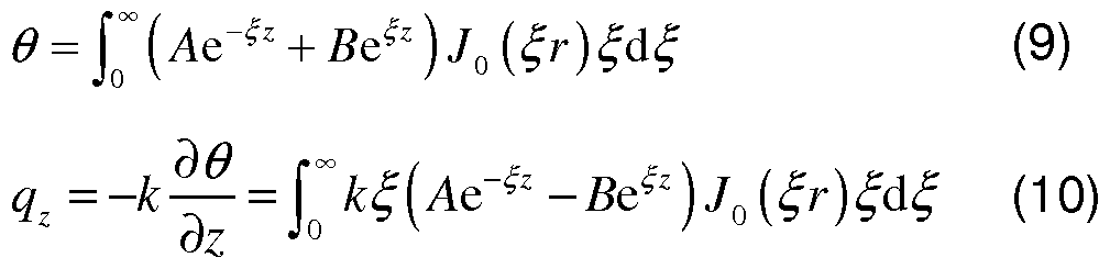
[00233] The boundary and continuity conditions can also be expressed in Hankel transform. Using (5-8), the two unknowns A and B for each layer can be solved. For glass,

B g = -A s e
For BC

For interconnect,


The temperature in each layer can be obtained by Eq. (9). For example, the temperature in interconnect is given by
Tm (r, z ) = T∞ + [ (Ame^ + Bm ' ) j0 {ξτ)ξάξ . (1 4)
The interconnect surface temperature is then obtained by setting z = h3. The LED temperature can be approximated by its average value over the entire active region as
2
Τ,ΕΒ = Τ^ (ΐ-ε-^ )Α^ (ξ ξ . (1 5)
[00234] The thermal conductivity of Al decreases as the film thickness decreases as shown in Figure 1 6. For the model described here, the thermal conductivity of Al is used as a fitting parameter, but with constraints to approximate literature values. In the case of 300 nm and 1 000 nm Al interconnects, the thermal conductivities of 70 W/m/k and 1 60 W/m/k, respectively, are used in the model. These values were compared with reported values to make sure they are within the reasonable range as depicted in Figure 1 6.
[00235] Finite element model to determine the temperature distribution. A 3D finite element model is established to study the temperature distribution in the LED system and validate the analytical model. Eight-node, hexahedral brick elements in the finite element software ABAQUS are used to discretize the geometry. A volume heat source is applied on the LED. The thermal convection boundary is applied at the air- interconnect interface and a constant temperature is applied at the bottom of the glass substrate. For LED arrays, a ¼ unit cell is used to take advantage of symmetry and periodic boundaries are applied. The finite element simulations agree well with analytical modeling as shown in Figure 1 7.
[00236] Experimental setup for measuring the LED temperature. The printed μ- ILED is placed on a heated chuck with a base temperature of 50 °C, and pixel-by- pixel calibration is performed to yield a reference irradiance image of an unpowered sample in order to account for the emissivity differences on the sample surface. In some cases, however, when the material has emissivity <0.1 , such as Al,
temperature measurement could be inaccurate due to very low thermal emission. A surface ink or polymer that emits as a blackbody can be placed on top of the sample and to eliminate variation in emissivity. This procedure was not used because of the destructive nature of this material to electrical devices. As a result, quantitative values were extracted for the temperature only at the open areas between Al interconnects.
REFERENCES
Tsao JY, Coltrin ME, Crawford MH, & Simmons JA (2010) Solid-state lighting: An integrated human factors, technology, and economic perspective. P IEEE 98:1 1 62- 1 179.
Schubert EF & Kim JK (2005) Solid-state light sources getting smart. Science 308:1274-1 278.
Chen G, et al. (2008) Performance of high-power I ll-nitride light emitting diodes, phys. stat. sol. (a) 205:1086-1 092.
Narukawa Y, lchikawa M, Sanga D, Sano M, & Mukai T (2010) White light emitting diodes with super-high luminous efficacy. J Phys D: Appl Phys 43:354002.
Solid-state lighting research and development: Multi-year program plan, (Energy USDo). available from http://www1 .eere.energy.gov/buildings/ssl/techroadmaps.html (201 0)
Karlicek Jr. RF (2005) High power LED packaging. CLEO.
Yeh H-JJ & Smith JS (1994) Fluidic self-assembly for the integration of GaAs light- emitting diodes on Si substrates. IEEE Photonic Tech L 6:706-708.
Kim D-H, et al. (2008) Materials and noncoplanar mesh designs for integrated circuits with linear elastic responses to extreme mechanical deformations. Proc Natl Acad Sci USA 105:1 8675-1 8680.
Park S-l, et al. (2009) Printed assemblies of inorganic light-emitting diodes for deformable and semitransparent displays. Science 325:977-981 .
Yoon J, et al. (2008) Ultrathin silicon solar microcells for semitransparent, mechanically flexible and microconcentrator module designs. Nat Mater 7:907-915.
Yoon J, et al. (2010) GaAs photovoltaics and optoelectronics using releasable multilayer epitaxial assemblies. Nature 465:329-334.
Meitl MA, et al. (2006) Transfer printing by kinetic control of adhesion to an elastomeric stamp. Nat Mater 5:33-38.
Lee J, et al. (201 1 ) Growth of high-quality InGaN/GaN LED structures on (1 1 1 ) Si substrates with internal quantum efficiency exceeding 50%. J Cryst Growth 315:263- 266.
Kumar V, Zhou L, Selvanathan D, & Adesida I (2002) Thermally-stable low- resistance Ti/AI/Mo/Au multilayer ohmic contacts on n-GaN. J Appl Phys 92:1712- 1714.
Baca AJ, et al. (2007) Printable single-crystal silicon micro/nanoscale ribbons, platelets and bars generated from bulk wafers. Adv Funct Mater 17:3051 -3062.
Bean KE (1978) Anisotropic etching of silicon. IEEE T Electron Dev ED-25:1 185- 1 193.
Kim R-H, et al. (2010) Waterproof AllnGaP optoelectronics on stretchable substrates with applications in biomedicine and robotics. Nat Mater 9:929-937.
Gong Z, et al. (2010) Size-dependent light output, spectral shift, and self-heating of 400 nm InGaN light-emitting diodes. J Appl Phys 107:01 3103.
Sou Z, Ma EY, Gleskova H, & Wagner S (1 999) Mechanics of rollable and foldable film-on-foil electronics. Appl Phys Lett 74:1 177-1 1 79.
Moon S-M & Kwak JS (2009) High-current electro-optical degradation of InGaN/GaN light-emitting diodes fabricated with Ag-based reflectors. J Korean Phys Soc
55:1 128-1 1 31 .
Arik M & Weaver S (2004) Chip scale thermal management of high brightness LED packages. Proc. of SPIE 5530:214-223
Senawiratne J, et al. (2008) Junction temperature measurements and thermal modeling of GalnN/GaN quantum well light-emitting diodes. J Electron Mater 37:607- 610.
Incropera FP, DeWitt DP, Bergman TL, & Layine AS. (2006) Introduction to heat transfer (Wiley).
Christiaens I, Roelkens G, Mesel KD, Thourhout DV, & Baets R. (2005) Thin-film devices fabricated with benzocyclobutene adhesive wafer bonding. J. Lightwave Technol. 23:517-523.
Lee SM, & Cahill G. (1997) Heat transport in thin dielectric films. J. Appl. Phys.
81 :2590-2595.
Bourgoin J-P, Allogho G-G, & Hache A (2010) Thermal conduction in thin films measured by optical surface thermal lensing. J Appl Phys 108:073520.
Schmidt AJ, Cheaito R, & Chiesa M (201 0) Characterization of thin metal films via frequency-domain thermoreflectance. J Appl Phys 107:024908.
Spina LL, et al. (2006) MEMS test structure for measuring thermal conductivity of thin films. Proc IEEE International Conference on Microelectronic Test Structures Austin, USA:137-142.
Stojanovic N, et al. (2007) Thin-film thermal conductivity measurement using microelectrothermal test structures and finite-element-model-based data analysis. J Microelectromech S 16:1269-1275.
Webb PW. (1991 ) Thermal imaging of electronic devices with low surface emissivity. Proc. Inst. Electr. Eng. 138:390-400
Sarua A, et al. (2006) Combined Infrared and Raman temperature measurements on device structures. CS Mantech Conf: 179-182.
Example 2: High Efficiency. Microscale GaN Light Emitting Diodes and Their
Thermal Properties on Unusual Substrates
[00237] This Example presents materials and assembly methods that enable efficient, ultrathin (slightly larger than 6 μιτι) LEDs based on GaN, with lateral dimensions ranging from -1 x1 mm2 to -25x25 μιη2, and their integration onto substrates of unconventional materials, including hydrogels. Quantitative
experimental and theoretical studies shows the benefits of thermal management that results from these geometries, for both continuous and pulsed mode operation, the latter of which demonstrates potential for use of these technologies in bio-integrated contexts.
[00238] Materials and processing schemes for inorganic light emitting diodes (LEDs) are increasingly important for applications in areas ranging from consumer electronics to energy efficient lighting. Conventional routes to devices involve epitaxial growth of active materials followed by wafer dicing and pick-and-place robotic manipulation into individually packaged components, for interconnection by bulk wire bonding. Recently reported schemes based on advanced methods in epitaxial liftoff and deterministic assembly allow devices with extremely thin geometries, in layouts that can be interconnected by planar metallization and photolithography. [1 6] Alternative, related strategies involve LEDs comprised of vertically aligned arrays of micro or nanowires to offer similar advantages, including the ability to form devices on thin, plastic substrates'7"81, but also with relaxed constraints on growth conditions. These and other recent advances have the potential to create new engineering opportunities and application possibilities for LED technologies. Even if flexible LEDs are in high demand and have a lot of applications, high efficiency and robust, flexible LEDs and their thermal analysis have not been addressed or only theoretical analysis'11 is reported. Importantly, these LEDs should be utilized in commercial/biomedical applications in the near future.
[00239] This Example presents materials and fabrication strategies that enable efficient, ultrathin (slightly larger than 6 μιτι) LEDs based on GaN, with lateral
dimensions ranging from -1 x1 mm2 to -25x25 μιη2, and their integration onto unconventional substrates. The process begins with high quality epitaxial material grown using state-of-the-art techniques on sapphire substrates, but with unusual methods for releasing this material in the form of completed devices suitable for assembly using the techniques of transfer printing. This strategy represents a significant improvement over recently reported [1] routes to similar classes of devices, which rely critically on comparatively low performance active materials grown on silicon. Particular additional points of emphasis in the following are theoretical and experimental aspects of heat dissipation with devices mounted on hydrogels and other 'soft' substrate materials, as models for their integration with organs of the body.
[00240] Figure 18 outlines the growth and processing steps, in a sequence of schematic illustrations, micrographs and images. Fig. 18A shows commercially obtained epitaxial material on sapphire, etched into square islands (100x1 00 μιη2) with L-shaped current spreading layers (Ni: 15 nm/Au 15 nm) and pads in the corners for top p-contacts (upper right; 25x25 μιη2; Cr: 15 nm / Au: 300 nm), and recessed n-contacts (lower left; 25x25 μιη2; Cr: 15 nm / Au: 300 nm). Details appear in the Methods section and in Fig. 23. Uniform deposition of a thin layer (200 nm) of SiNx passivates and protects the top surfaces and sidewalls of these structures, as preparation for coating with a bilayer of Cr (adhesion layer: 15 nm) / Pd (150 nm) that facilitates bonding to another substrate (silicon or glass) which supports metallization of Cr (adhesion layer: 1 5 nm) / Pd (150 nm) / In (900 nm). Bonding at pressures and temperatures of 400 bar and 220 °C, respectively, causes the In (melting point -156 °C; Brinell hardness 8.83 MPa (cf. lead (Pb): 38.3 MPa))[9] to flow and partially fill the recessed n-contacts and the trenches between the devices. A fraction of the In forms an alloy with the Pd, [10 1 1] to form a solid layer (lnPdx) that prevents cracking in the LEDs during subsequent processing, including laser lift off (LLO) as described next.
[00241] Passing light from a krypton fluoride (KrF) (0.9 J/cm2, 248 nm wavelength) or yttrium aluminum garnet (YAG): Nd laser (0.3 J/cm2, 266 nm, single pulse with 5 ns exposure time) through the sapphire leads to strong absorption at the interface with the GaN, where thermal decomposition forms Ga metal and nitrogen gas.
Pressure associated with this process releases the GaN from the sapphire, in the form of individual microscale inorganic LEDs (μ-ILEDs). Heating to 70 °C (melting point of Ga is 29.7 °C[9]) and applying mild mechanical force enables complete removal of the sapphire, as in Fig. 1 8B and Fig. 24. Immersing the exposed μ-ILEDs in dilute HCI (5 wt%) etches away the residual Ga, to yield clean surfaces on top. This same etchant removes unalloyed In, leaving only agglomerates of lnPdx. This remaining metal is important because it tethers the μ-ILEDs to the underlying substrate, in their transferred locations. The micrograph in Fig. 18C shows a sample after these process steps. The tilted scanning electron microscope (SEM) image in the inset reveals voids and lnPdx agglomerates between a representative μ-ILED and the substrate.
[00242] Contacting a bulk slab of poly(dimethylsiloxane) (PDMS) that has an array of vertical pillars (3 μιη in diameter, 1 .2 μιη in height, and 5 μιη spacings) embossed on its surface, and then peeling it away retrieves, in a single step, all of the μ-ILEDs from their substrate via separation at the contact points defined by the lnPdx, leaving the devices bound by van der Waals forces to the structured surface of the PDMS. Etching the exposed Pd and Cr layers removes all residual metal particles (Fig. 25 shows a Si wafer after removal of all μ-ILEDs) including, by liftoff, any remaining particulates of lnPdx. Fig. 1 8D presents optical micrographs of the results; the inset shows an individual μ-ILED on a structured PDMS slab. (As shown in this image, a fraction of the devices, typically -10%, undergo some translational and rotational misalignment during the transfer. This aspect of the process can be further minimized through optimized processing, or it can be accommodated in the steps described next.) Techniques of transfer printing are used to remove individual μ- ILEDs, or selected collections of them, from this PDMS slab and then to deliver them to nearly any substrate of interest, where they can be electrically interconnected to yield functional lighting systems using procedures described elsewhere (see Fig. 26-28) The printed μ-ILEDs on PET or any other transparent substrates were electrically interconnected after passivation by a "back side exposure" method[1] using light sensitive tone resist. In case of a non-transparent, high heat dissipation substrate, like Al foil, the whole device layer including the printed μ-ILED and interconnects is transferred onto a non-transparent substrate (i.e. Al foil) by
additional transfer printing. The main focus of work presented here corresponds to systems in which the densely arrayed μ-ILEDs on the structured PDMS are distributed over large areas, in sparse coverages on soft substrates. Fig. 18E (left) shows an interconnected string of 12 μ-ILEDs on a strip (5x40 mm2) of poly(ethylene terephthalate) (PET, 50 μιη thick; Grafix® Dura-Lar™ film roll) and a square array of 100 μ-ILEDs on glass (right). Comparisons of performance in μ-ILEDs on sapphire and on PET (50 μιη thick) (Fig. 19 A-D) reveal nearly identical behaviors at low power. At high power, the μ-ILEDs on sapphire show a slight blue-shift in emission wavelength (from 447 nm at 1 mA to 445.2 nm at 10 mA), consistent with charge accumulation that results from band filling effects described previously [12 13]. By contrast, μ-ILEDs on PET exhibit red-shift (from 447.3 nm at 1 mA to 451 .7 nm at 10 mA) due to heating associated with the low thermal conductivity of the PET
(compared to the sapphire). [13] (See Fig. 29 and 30.) Figure 19 shows a comparison of the μ-ILED properties to a commercialized LED. These properties can be enhanced through optimized processing and use of a high quality wafer stack.
[00243] As suggested by previous thermal modeling results, an advantage of μ- ILEDs on plastic substrates is their accelerated rates of passive heat spreading due to favorable size scaling effects in thermal transport. [1] The strategy of Fig. 18 is compatible with a wide range of μ-ILED sizes (much wider than previously possible111), in a manner that allows the first quantitative experimental investigations of these effects. Fig. 20A shows examples, from 1 x 1 mm2, 500x500 μιη2, 300x300 μιη2, 1 50x 1 50 μιη2, 100x 1 00 μιη2, 75x75 μιη2, 50x50 μιη2 to 25x25 μιη2. This size range spans the commercial regime to dimensions limited only by resolution and alignment accuracy set by tools for photolithography used in this work. Even the largest devices show spatially uniform emission across the active regions (Fig. 20B). Studies of size dependent operational characteristics over this available range illustrate clearly the relevant behaviors. Fig. 20C, for example, shows a sharp decrease in operating temperatures of μ-ILEDs on a 50 μιη thick PET substrate, at the same power per unit area, with decreasing μ-ILED size. The results are significant reductions in the operating temperatures, and corresponding
enhancements in efficiency (Fig. 20C). These improvements can be illustrated in
plots of the input and output power densities, shown in Fig. 20D. The overlap of these data at low power densities demonstrates that the beneficial aspects of small device geometries (in the regime studied) are due mostly to thermal effects and not, for example, to increases in optical output coupling efficiency which might also occur. These output power and junction temperature results from LEDs on PET show quite similar trends compared to LEDs on sapphire. [12 13]
[00244] This improvement in thermal behavior with decreasing size can be exploited by structuring an LED with conventional dimensions into an array of interconnected μ-ILEDs with sufficient spacing, as suggested theoretically in our recent report.[1] Figure 21 provides detailed experimental evidence of the effects. Here, two device designs are compared (Fig. 21 A). The first involves a single, 500x500 m2 μ-ILED; the second is a 5 by 5 array of 100x100 μιη2 μ-ILEDs, separated by 200 μιη. Fig. 21 B and Fig. 32 show heat dissipation results for the first case (red symbols o experimental; black lines - analytical models; black symbols■ finite element models) at 40 mW of applied power at room temperature. The peak device temperature is -86 °C, with a characteristic lateral decay length of -200 μιη along the PET substrate (-50 μιη thick). Separating adjacent μ-ILEDs in the 5x5 array by slightly more than 200 μιη can yield significant reductions in peak
temperatures. Measurements on arrays with various separations were performed; the results for the peak temperatures appear in Fig. 21 C and Fig. 33-36, at applied powers of 20 mW and 40 mW. (The characteristic lateral decay length will be sensitive to many parameters, including the PET thickness, i.e. increasing the thickness increases this length. Some modeling results appear in Fig. 30-37.)
[00245] As with the thickness, the intrinsic thermal properties of the substrate materials have a large effect on heat dissipation, consistent with expectation. Figure 22 shows results from two dramatically different cases: 700 μιη thick Al foil and 2 mm thick hydrogel. The μ-ILED on Al foil reaches only 48 °C at 40 mW of applied power (Fig. 22A and Fig. 38) and it cannot be degraded even after 5 min operation while an identical one on hydrogel reaches 65 °C even at only 5 mW (Fig. 22B and Fig. 39). At 40 mW, this latter case leads to strong degradation of both the device and the substrate even at 5 sec operation, due to the high temperatures that are reached (cf. 232 °C at 30 mW). Nevertheless, as discussed above, small device
geometries create opportunities for reliable operation even on such substrates, thereby demonstrating their potential use on or under the skin or integrated with internal tissues of the body. Here, pulsed mode can provide additional benefits, especially in applications of optogenetics, where the biological response can be suppressed with continuous mode operation. [1 ] The thermal behaviors under pulsed operation are shown in Fig. 22C for an μ-ILED on hydrogel, to simulate biological tissue, for various duty cycles (1 , 10, 30, 50, 70, 90 and 100 %) at 30 mW peak power. The various duty cycles of 1 , 10, 30, 50, 70, 90 and 100% correspond to on and (off) times of 10 με (990 με), 100 με (900 με), 300 με (700 με), 500 με (500 με), 700 με (300 με), 900 με (100 με). As can be seen in simulation results in Fig. 22C (black symbols, o(minimum) and•(maximum temperature)) and right images of Figs. 22D, 40 and 41 , the time dependent behavior of the temperature reflects the pulsed operational mode, with decreases in temperature between pulses, due to thermal diffusion. As the duty cycle decreases, so does the temperature, from 232 °C at 100 % (Fig. 40) to 30.3 °C at 1 % (Fig. 22D and Fig. 42). For the regimes of operation explored here, reducing the duty cycle of the pulsed mode at short period (less than 1 ms) has similar effects to reducing the average power in a continuous (i.e. non- pulsed) mode (Fig. 43). For example, the temperature of a μ-ILED with 50 % duty cycle and 1 ms period at 30 mW is about 128 °C (maximum and minimum of 154 °C and 102 °C, respectively), similar to the temperature (125 °C) at 15 mW continuous power. The characteristic times for passive cooling in this case are -20 ms. (Fig. 22E) The pulsed mode shows promise for achieving challenging requirements in optogenetics, where peak powers must be -10 mW/mm2 with sustained changes in temperature of less than 1 -2 °C.[1 ]
[00246] The results reported here demonstrate that state-of-the-art GaN epitaxial materials grown on sapphire substrates can be manipulated in the form of μ-ILEDs, for use in applications that would be difficult or impossible to address with
conventional LED technologies.
Experimental Section
[00247] Delineating μ-ILEDs and forming Ohmic contacts on them. The fabrication began with GaN epitaxially grown on a double-sided polished sapphire wafer (2 inch
diameter; Cermet Inc.). The epitaxial layers consisted of undoped GaN (3.8 μιη), n- type doped GaN (2 μιη), multiple quantum wells (0.14 μητι), and p-type doped GaN (0.2 μιη). Rinsing with diluted HCI (HCI:DI=1 :3) for 5 min removed residual metal ions and oxided GaN. Sputter deposition (AJA, ATC 2000) formed a bilayer of Ni (1 5 nm) and Au (15 nm) as a thin p-contact. Wet etching the Au (for 3 s) and Ni (for 2 min) with commercial etchants (Transene) patterned this bilayer into a L-shape for effective current spreading. The sample was annealed in an oxygen and nitrogen atmosphere at 500 °C for 5 min to enhance the contact properties. Next, patterning photoresist near the inner edges of the L-shaped pad and then removing the exposed epitaxial material by chlorine based inductively coupled reactive ion etching (ICP-RIE; PlasmaTherm, SLR-770) formed square (40x40 μιη2) recessed regions to open access to the n-type layers at the base. In a single step, contact pads to the n- and p- regions, each 25x25 μιη2, were formed by electron beam evaporation (Temescal, FC-1800) of 15 nm of Cr and then 300 nm of Au. A low-stress silicon nitride (200 nm; SiNx) was then formed uniformly over the entire substrate, using plasma enhanced chemical vapor deposition (PECVD; STS, Mesc Multiple). Next, a negative tone photoresist (PR, 7 μιη thick; MicroChemicals Inc., AZ nLOF 2070) was patterned by photolithography, to serve as a mask for etching the SiNx as well as the GaN to define the lateral dimensions of arrays of μ-ILEDs. As a final step, residual PR was removed by immersion in piranha solution (3:1 mixture of surfuric acid with hydrogen peroxide at 90 5C) for 5 min.
[00248] Bonding and Laser Lift Off (LLO). After delineating and forming contacts for the μ-ILEDs, another layer of SiNx (200 nm) was deposited for passivation, as preparation for wafer bonding and transfer. The process used Cr (15 nm) / Pd (1 50 nm) on the SiNx-coated μ-ILED substrate and Cr (15 nm) / Pd (150 nm) / In (900 nm) on a target silicon wafer. The bonding occurred upon contact with a pressure of 400 bar and heating to 220 °C. The LLO used 0.9 J/cm2 from a krypton fluoride (KrF) laser (JSPA, excimer laser with 248 nm wavelength) or 0.3 J/cm2 from yttrium aluminum garnet (YAG) laser (Sandia Nat. Lab, third harmonic of a Q-switched YAG:Nd laser, 266 nm wavelength, single pulse with 5 ns exposure time), directed through the polished bottom surface of the sapphire. Absorption occurred at the GaN-sapphire interface, to cause decomposition of the undoped GaN into nitrogen (N2) and gallium (Ga) metal according to: 2GaN→ 2Ga (m) + N2 (g). The sample
was then heated to 70 °C, to melt the Ga. Afterward, the sapphire substrate could be removed easily, to complete the transfer of GaN.
[00249] Transfer printing individual μ-ILEDs. Immersion in dilute HCI (5 % volume ratio) removed the unalloyed In in the vicinity of the bonding layer. The In-Pd alloy was not removed in this etchant, thereby leaving it to serve as distributed tethers (i.e. anchors) to hold the μ-ILEDs to the underlying silicon. Next, the residual Pd and Cr material on the passivated μ-ILEDs was eliminated by Pd and Cr etchant (Transene Inc.), respectively. Contacting a bulk slab of PDMS with an array of vertical pillars (3 μιη in diameter, 1 .2 μιη in height, and 5 μιη in space) against the processed substrate and then quickly peeling it back transferred all of the μ-ILEDs to the structured surface of the PDMS. Etching the exposed Pd and Cr layers removed substantially all residual metal. A PDMS stamp with posts (100 χ 100 μιη and heights of 100 μιη) was positioned above the μ-ILEDs to allow their retrieval and printing to a substrate of interest. The printing was performed using a slightly modified mask aligner (Karl Suss, MJB) or an automated printing machine. The structured PDMS slab is important because it allows the μ-ILEDs to be flipped over for further processing, in a way that provides sufficiently weak adhesion (defined by van der Waals interactions, and contact area) for efficient retrieval by transfer printing.
[00250] Interconnect. To form interconnected arrays of μ-ILEDs, or for electrically probing individual devices, the SiNx layer was first etched away by reactive ion etching (RIE; a mixture of CF (40 seem) and 02 (1 .2 seem); Plasmatherm 790). Coating with an adhesion promoter (Dow, AP3000) and then a layer of
photosensitive benzocyclobutene (6 μιη thick; BCB) prepared the devices for backside exposure to ultraviolet light, through a transparent substrate. This light exposes the BCB in all regions except those above the opaque n-, and p- contact pads. Developing away the unexposed BCB (Advanced Developer, DS21 00) and blowing with a stream of N2 removed the residual developer, to complete the patterning process. After fully curing the BCB in an Ar atmosphere glove box, remaining BCB residue was removed by oxygen RIE. To form metallization lines to the contacts, 15 nm of Cr and 300 nm of Au were sputtered, and then etched using a mask of patterned PR.
[00251 ] Characterization of electrical, optical and thermal properties. A
semiconductor parameter analyzer (4155C, Agilent) was used to measure the electrical properties. Optical measurements of the emission spectra and light output were performed with a spectrometer (H R4000 and FOIS-1 fiber optics integrating sphere, Ocean Optics). Radiant efficiency was simply calculated by Pout/Pin- Thermal measurements were performed using a MWIR-based InDb thermal imager (InfraScope, GFI) with a base temperature of 30°C.
REFERENCES
[1 ] H. -S. Kim, E. Brueckner, J. Song, Y. Li, S. Kim, C. Lu, J. Sulkin, K. Choquette, Y. Huang, R. G. Nuzzo and J. A. Rogers, Proc. Natl. Acad. Sci. L/S \ 201 1 , 1 08, 10072.
[2] S. -I. Park, Y. Xiong, R. -H. Kim, P. Elvikis, M. Meitle, D. -H. Kim, J. Wo, J. Yoon, C. -J. Yu, Z. Liu, Y. Huang, K. -c. Hwang, P. Ferreira, X. Li, K. Choqqette, and J. A. Rogers, Science, 2009, 325, 977.
[3] X. Hu, P Kull, B. d. Graff, K. Dowling, J. A. Rogers, and W. J. Arora, Adv. Mater. 201 1 , 23, 2933.
[4] R. -H. Kim, M. -H. Bae, D. G. Kim, H. Cheng, B. H. Kim, D. -H. Kim, M. Li, J. Wu, F. Du, H. -s. Kim, S. Kim, D. Estrada, S. W. Hong, Y. Huang, E. Pop, and J. A. Rogers, Nano Lett. 201 1 , 1 1 . 3881 .
[5] R. -H. Kim, D. -H. Kim, J. Xiao, B. H. Kim, S. -I. Park, B. Panilaitis, R. Ghaffari, J. Yao, M. Li, Z. Lui, V. Malyarchuk, D. G. Kim, A. -P. Le, R. G. Nuzzo, D. L. Kaplan, F. G. Omenetto, Y. Huang, Z. Kang, and J. A. Rogers, Nat. Mater. 2010, 9, 929.
[6] K. J. Lee, J. Lee, H. Hwang, Z. J. Reitmeier, R. F. Davis, J. A. Rogers, and R. G. Nuzzo, Small, 2005, 1 , 1 164.
[7] K. Chung, C. -H. Lee and G. -C. Yi, Science 201 0, 330, 655
[8] C. -H. Lee, Y. -J. Kim, Y. J. Hong, S. -R. Jeon, S. Bae, B. H. Hong, and G. -C. Yi, Adv Mater. 201 1 , 23, 4614.
[9] W. Assmus et al, in Handbook of Condensed Matter and Materials Data, (Eds: W. Martinessen and H. Warlimont), Springer, Berlin, Germany 2005, Part 2.))
[10] Scientific group thermodata Europe (SGTE), P. Franke, D. Neuschutz,
Thermodynamics Properties, In-Pd (Indiun-Palladiun), Vol 19B5: Binary Systems part 5 (Eds: P. Franks, D. Neuschutz), SpringerMaterials, 2007.
[1 1 ] (a)W. S. Wong, 1999, Integration of GaN thin films with dissimilar substrate materials by wafer bonding and laser lift- off, PhD thesis, University of California at Berkeley, USA.; (b) W. S. Wong, T. Sands, N. W. Cheung, M. KneissI, D. P. Bour, P. Mei, L. T. Romano, N. W. Johnson, Appl. Phys. Lett. 2000, 77, 2822.
[12] B. -J. Pong, C. -H. Chen, S. -H. Yen, J. -F. Hsu, C. -J Tun, Y. -K. Kuo, C. -H. Kuo and G.-C. Chi, Solid State Electron. 2006, 50, 1588.
[13] Z. Gong, S. Jin, Y. Chen, J. Mckendry, D. Massoubre, I. M. Watson, E. Gu and M. D. Dawson, J. Applied Phys. 2010, 107, 013103.
[14] M. E. Llewellyn, K. R. Thompson, K. Deisseroth, and S. L. Delp, Nat. Medicine, 2010, 16, 1 161 .
Analytical Model of printed μ-ILED on a PET substrate
[00252] The approximately axisymmetric nature of the problem allows an analytical study of the thermal transport properties. The LED is modeled as a disk heat source with the total heat generation Q and a radius r0 = L/ n; such that it yields the same area as a square (Lx L) LED. Schematic illustration of the device geometric and thermal parameters used in the model is shown in Fig. 31 . The BCB layer encapsulating the entire LED on a PET substrate (thickness Hp and thermal conductivity kp ) can be divided into two layers. The top layer (thickness HB and thermal conductivity kB ) is BCB only while the bottom layer (thickness HL and thermal conductivity kL ) includes both BCB and LED.
[00253] The temperature distribution T (r, z) at each layer can be obtained from the steady-state heat transfer governing equation— T+ +— = 0 in cylindrical
dr r dr ¾
coordinates (r, z) with the origin coincident with the center of the heat source. The boundary conditions include constant temperature T = T∞ at the bottom surface
{ z = -Hp - HL ) of PET and natural convection -kB dT/dz = h(T -T∞) at the top surface
( z = HB ) of BCB, where h is the coefficient of natural convection. At the interface z =—HL , the temperature and heat flux are continuous, i.e., = 0 ,

where [ ] stands for the discontinuit between two ad acent la ers. At the interface z = 0 , [r] = 0 holds for all r, for r≤r0 . The

steady-state heat transfer governing equation can be solved via Hankel
transformation. The surface temperature is obtained as
2kB
(1 )
r0 . For

the temperature within the active region ( r < r0), it is approximately a constant (See Fig. 21 B), which can be approximated by the average value as
Surface (Γ' Γ— Γ0 ) ^∞ + I £
(2)
The LED temperature is given by
Tu = T∞ + - Γ ( 1 + ¾ ) ( ξτ, ) AB d ξ
(3)
[00254] Figure 20C shows surface temperature in Eq. (2) versus the LED size for a power density 1 6W/cm2, ambient temperature T∞ = 30 °C , coefficient of natural convection h = 25 W/m2/K [1 ], thicknesses Hp = 15 i , HL = 6.54 m and
HB
 and
kB = 0.3 W/m K [3], where kL is an effective thermal conductivity that accounts for the 3D effect of LED. The analytical results agree well with experiments (Fig. 21 C). The temperature profile shown in Fig. 21 B also agrees well with experiments and 3D finite element analysis.
and
kB = 0.3 W/m K [3], where kL is an effective thermal conductivity that accounts for the 3D effect of LED. The analytical results agree well with experiments (Fig. 21 C). The temperature profile shown in Fig. 21 B also agrees well with experiments and 3D finite element analysis.
[00255] The method of superposition is used to determine the temperature of μ- ILED arrays based on the solution for a single LED, i.e.,
( r ' z) = τ °° +∑
 ] > where Tt (r, z) is the temperature distribution due to the /* μ-ILED. The surface temperature distributions for a single 500x500 μιη2 μ- ILED and 5 by 5 arrays of 100x 100 μιη2 μ-ILEDs with different separations are shown in Fig. 33-36 at applied powers of 20 mW and 40 mW. The maximum temperature occurs at the center of the array and it decreases with increasing the spacing (Fig. 21 C). Once the spacing is larger than the characteristic lateral decay length -200 μιη, the temperature remains unchanged and is equal to that of a single 100x 100 μιη2 μ-ΙίΕΟ.
Finite element model to determine the temperature distribution
[00256] A 3D finite element model is established using ABAQUS finite element software to obtain the temperature distribution in the LED systems (LED on a PET substrate in Fig. 31 , LED on an aluminum substrate in Fig. 38 and LED on a hydrogel substrate in Fig. 39). The geometry is discretized by eight-node, hexahedral brick elements. A volume heat source is applied on the LED. The thermal convection boundary condition is imposed at the air-BCB or air-SU8 interface and a constant temperature is applied at the bottom of the substrate.
[00257] The thermal properties for the LED/PET system are given in the previous section. The properties for LED/aluminum and LED/hydrogel include the thermal conductivity, thermal capacity and mass density of 0.2 W/m/K, 1200 J/kg/K and 1 190 kg/m3 for SU8 [4,5], 0.52 W/m/K, 1 150 J/kg/K and 1430 kg/m3 for PI [6,7], 0.6 W/m/K, 2375 J/kg/K and 1 1 1 2 kg/m3 for hydrogel [8], and 148 W/m/K, 700 J/kg/K and 2330 kg/m3 for an LED that is approximated by the properties of Si [9]. The thermal conductivity of aluminum and PDMS are 237 W/m/K [10] and 0.1 5 W/m/K [1 1 ],
respectively. The comparisons of FEM simulations with experiments for constant power and pulsed power are shown in Fig. 22 and Fig. 40-42.
REFERENCES
[1 ] F. P. Incropera, D. P. DeWitt, T. L. Bergman, and A. S. Lavine A.S.,
"Fundamentals of Heat and Mass Transfer", Wiley, Hoboken (2007).
[2] J.G. Speight, "Lange's handbook of chemistry (16 ed.)", McGraw-Hill (2005).
[3] A. Modafe, N. Ghalichechian, M. Powers, M. Khbeis, and R. Ghodssi, Embedded benzocyclobutene in silicon: An integrated fabrication process for electrical and thermal isolation in MEMS, Microelectronic Engineering 82, 1 54-1 67 (2005).
[4] B. Solano, S. Rolt and D. Wood, Thermal and mechanical analysis of an SU8 polymeric actuator using infrared thermography, Proc. IMechE 222 Part C: J.
Mechanical Engineering Science, 73-86 (2007).
[5] C.G. Mattsson, G. Thungstrom, K. Bertilsson, H.E. Nilsson, and H. Martin, Development of an infrared thermopile detector with a thin self-supporting SU-8 membrane, IEEE SENSORS 2007 Conference, 836-839 (2007).
[6] A.P. Dhorajiya, M.S. Mayeed, G.W. Auner, R.J. Baird, G.M. Newaz, R. Patwa, and H. Herfurth, Finite element thermal/mechanical analysis of transmission laser microjoining of titanium and polyimide, Journal of Engineering Materials and Technology 32, 01 1004 (2010).
[7] Z. Hu, B. Carlberg, C. Yue, X. Guo, and J. Liu, Modeling of nanostructured polymer-metal composite for thermal interface material applications, 2009
International Conference on Electronic Packaging Technology & High Density Packaging, 481 -484 (2009).
[8] N.S. Satarkar, S.A. Meenach, K.W. Anderson, and J.Z. Hilt, Remote actuation of hydrogel nanocomposites: heating analysis, modeling and simulations, AICHE Journal 57, 852-860 (201 1 ).
[9] S.A. Campbell, "The Science and Engineering of Microelectronic Fabrication", Oxford University Press, New York (2001 ).
[10] J. P. Bourgoin, G.G. Allogho, A. Hache, Thermal conduction in thin films measured by optical surface thermal lensing, Journal of Applied Physics 108, 073520 (2010).
[1 1 ] J. E. Mark (ed.), "Polymer Data Handbook", Oxford University Press, New York (1 999).
STATEMENTS REGARDING INCORPORATION BY REFERENCE
AND VARIATIONS
[00258] All references throughout this application, for example patent documents including issued or granted patents or equivalents; patent application publications; and non-patent literature documents or other source material; are hereby
incorporated by reference here in their entireties, as though individually incorporated by reference, to the extent each reference is at least partially not inconsistent with the disclosure in this application (for example, a reference that is partially
inconsistent is incorporated by reference except for the partially inconsistent portion of the reference).
[00259] The terms and expressions which have been employed herein are used as terms of description and not of limitation, and there is no intention in the use of such terms and expressions of excluding any equivalents of the features shown and described or portions thereof, but it is recognized that various modifications are possible within the scope of the invention claimed. Thus, it should be understood that although the present invention has been specifically disclosed by preferred embodiments, exemplary embodiments and optional features, modification and variation of the concepts herein disclosed may be resorted to by those skilled in the art, and that such modifications and variations are considered to be within the scope of this invention as defined by the appended claims. The specific embodiments provided herein are examples of useful embodiments of the present invention and it will be apparent to one skilled in the art that the present invention may be carried out using a large number of variations of the devices, device components, method steps set forth in the present description. As will be obvious to one of skill in the art, methods and devices useful for the present methods can include a large number of optional composition and processing elements and steps.
[00260] When a group of substituents is disclosed herein, it is understood that all individual members of that group and all subgroups, including any isomers, enantiomers, and diastereomers of the group members, are disclosed separately. When a Markush group or other grouping is used herein, all individual members of the group and all combinations and subcombinations possible of the group are intended to be individually included in the disclosure. When a compound is described herein such that a particular isomer, enantiomer or diastereomer of the compound is not specified, for example, in a formula or in a chemical name, that description is intended to include each isomers and enantiomer of the compound described individually or in any combination. Additionally, unless otherwise specified, all isotopic variants of compounds disclosed herein are intended to be encompassed by the disclosure. For example, it will be understood that any one or more hydrogens in a molecule disclosed can be replaced with deuterium or tritium. Isotopic variants of a molecule are generally useful as standards in assays for the molecule and in chemical and biological research related to the molecule or its use. Methods for making such isotopic variants are known in the art. Specific names of compounds are intended to be exemplary, as it is known that one of ordinary skill in the art can name the same compounds differently.
[00261] Many of the molecules disclosed herein contain one or more ionizable groups [groups from which a proton can be removed (e.g., -COOH) or added (e.g., amines) or which can be quaternized (e.g., amines)]. All possible ionic forms of such molecules and salts thereof are intended to be included individually in the disclosure herein. With regard to salts of the compounds herein, one of ordinary skill in the art can select from among a wide variety of available counterions those that are appropriate for preparation of salts of this invention for a given application. In specific applications, the selection of a given anion or cation for preparation of a salt may result in increased or decreased solubility of that salt.
[00262] Every formulation or combination of components described or exemplified herein can be used to practice the invention, unless otherwise stated.
[00263] Whenever a range is given in the specification, for example, a temperature range, a time range, a range of one or more physical dimensions (e.g., length, width, thickness, etc.) or a composition or concentration range, all intermediate ranges and
subranges, as well as all individual values included in the ranges given are intended to be included in the disclosure. It will be understood that any subranges or individual values in a range or subrange that are included in the description herein can be excluded from the claims herein.
[00264] All patents and publications mentioned in the specification are indicative of the levels of skill of those skilled in the art to which the invention pertains.
References cited herein are incorporated by reference here in their entirety to indicate the state of the art as of their publication or filing date and it is intended that this information can be employed herein, if needed, to exclude specific embodiments that are in the prior art. For example, when compositions of matter are claimed, it should be understood that compounds known and available in the art prior to Applicant's invention, including compounds for which an enabling disclosure is provided in the references cited herein, are not intended to be included in the composition of matter claims herein.
[00265] Unless defined otherwise, all technical and scientific terms used herein have the same meanings as commonly understood by one of ordinary skill in the art to which this invention belongs. Although any methods and materials similar or equivalent to those described herein can be used in the practice or testing of the present invention, the preferred methods and materials are now described. Nothing herein is to be construed as an admission that the invention is not entitled to antedate such disclosure by virtue of prior invention.
[00266] As used herein, "comprising" is synonymous with "including," "containing," or "characterized by," and is inclusive or open-ended and does not exclude additional, unrecited elements or method steps. As used herein, "consisting of" excludes any element, step, or ingredient not specified in the claim element. As used herein, "consisting essentially of" does not exclude materials or steps that do not materially affect the basic and novel characteristics of the claim. In each instance herein any of the terms "comprising", "consisting essentially of" and "consisting of" may be replaced with either of the other two terms. The invention illustratively described herein suitably may be practiced in the absence of any element or elements, limitation or limitations which is not specifically disclosed herein.
[00267] It must be noted that as used herein and in the appended claims, the singular forms "a", "an", and "the" include plural reference unless the context clearly dictates otherwise. Thus, for example, reference to "a cell" includes a plurality of such cells and equivalents thereof known to those skilled in the art, and so forth. As well, the terms "a" (or "an"), "one or more" and "at least one" can be used
interchangeably herein. It is also to be noted that the terms "comprising", "including", and "having" can be used interchangeably. The expression "of any of claims XX- YY" (wherein XX and YY refer to claim numbers) is intended to provide a multiple dependent claim in the alternative form, and in some embodiments is
interchangeable with the expression "as in any one of claims XX- YY."
[00268] One of ordinary skill in the art will appreciate that starting materials, biological materials, reagents, synthetic methods, purification methods, analytical methods, assay methods, and biological methods other than those specifically exemplified can be employed in the practice of the invention without resort to undue experimentation. All art-known functional equivalents, of any such materials and methods are intended to be included in this invention. The terms and expressions which have been employed are used as terms of description and not of limitation, and there is no intention in the use of such terms and expressions of excluding any equivalents of the features shown and described or portions thereof, but it is recognized that various modifications are possible within the scope of the invention claimed. Thus, it should be understood that although the present invention has been specifically disclosed by preferred embodiments and optional features, modification and variation of the concepts herein disclosed may be resorted to by those skilled in the art, and that such modifications and variations are considered to be within the scope of this invention as defined by the appended claims.
Claims
1 . An electronic device comprising: a substrate; and an array of light emitting diodes (LEDs) supported by said substrate, said array of LEDs comprising: a plurality of printable LED elements, wherein each LED element in said array of LEDs has one or more lateral dimensions less than or equal to 1000 μιη and a thickness dimension less than or equal to 50 μιη, and wherein a spacing between adjacent LED elements in said array of LEDs is greater than or equal to at least one lateral dimension of an LED element in said array; and a plurality of electrical interconnects, wherein each LED element in said array of LEDs is positioned in electrical communication and thermal communication with at least two of said plurality of electrical interconnects, wherein each of said electrical interconnects has lateral dimensions and an average thickness large enough to provide dissipation of heat from said array of LEDs at a rate greater than or equal to 5 μύ s~1.
2. An electronic device comprising: a substrate; and an array of light emitting diodes (LEDs) supported by said substrate, said array of LEDs comprising: a plurality of printable LED elements, wherein each LED element in said array of LEDs has one or more lateral dimensions less than or equal to 1000 μιη and a thickness dimension less than or equal to 50 μιη, and wherein a spacing between adjacent LED elements in said array of LEDs is greater than or equal to 2 μιη; and a plurality of electrical interconnects, wherein each LED element in said array of LEDs is positioned in electrical communication with at least two of said plurality of electrical interconnects, wherein each of said electrical interconnects is characterized by lateral dimensions and an average thickness.
3. The electronic device of any of claims 1 -2, wherein said lateral dimensions and said average thickness of said electrical interconnects are large enough to provide heat dissipation from each of said LEDs in said array during operation at a rate selected over the range of 5 μύ s"1 to 100 J s"1.
4. The electronic device of any of claims 1 -3, wherein said lateral dimensions and said thickness of said electrical interconnects are large enough to provide a maximum temperature of each of said LEDs in said array less than or equal to 373 K for a power consumption equal to or greater than 5 μ\Λ .
5. The electronic device of any of claims 1 -4, wherein a net heat capacity of said electrical interconnects is greater than or equal to 7.3 x 10"11 J/K per LED in said array.
6. The electronic device of any of claims 1 -5, wherein each of said electrical interconnects of said array has an average heat capacity equal to or greater than 7.3 x 10"11 J/K.
7. The electronic device of any of claims 1 -6, wherein an average thermal
conductivity of each of said electrical interconnects is a factor of 0.4 to 50 of an average thermal conductivity of said LED elements.
8. The electronic device of any of claims 1 -7, wherein an average thermal
conductivity of each of said electrical interconnects is a factor of 0.44 to 1 .54 of an average thermal conductivity of said LED elements.
9. The electronic device of any of claims 1 -8, wherein said array has a density of said LED elements less than or equal to 1 00 LEDs mm"2.
10. The electronic device of any of claims 1 -9, wherein said array has a density of said LED elements selected over the range of 1 LEDs mm"2 to 81 LEDs mm"2
1 1 . The electronic device of any of claims 1 -1 0, wherein a spacing between adjacent LED elements in said array of LEDs is greater than or equal to 1 0 Mm.
12. The electronic device of any of claims 1 -1 1 , wherein said spacing between adjacent LED elements in said array of LEDs is selected over the range of 2 μιη to 10 cm.
13. The electronic device of any of claims 1 -1 2, wherein said array has an
average spacing between adjacent LED elements selected over the range of 10 m to 100 m.
14. The electronic device of any of claims 1 -1 3, wherein each LED element in said array of LEDs has lateral dimensions less than or equal to 500 μιη.
15. The electronic device of any of claims 1 -14, wherein each of said LED
elements in said array has average lateral dimensions selected over the range of 10 m to 1 mm.
16. The electronic device of any of claims 1 -1 5, wherein said lateral dimensions of each of said LED elements are selected over the range of 10 m to 500 Mm.
17. The electronic device of any of claims 1 -1 6, wherein each of said LED
elements in said array has average lateral dimensions selected over the range of 10 Mm to 500 Mm.
18. The electronic device of any of claims 1 -1 7, wherein said thickness dimension of each of said LED elements is less than or equal to 10 Mm.
19. The electronic device of any of claims 1 -1 8, wherein said thickness dimension of each of said LED elements is selected over the range of 500 nm to 50 Mm.
20. The electronic device of any of claims 1 -1 9, wherein each of said LED
elements in said array has an average thickness dimension selected over the range of 500 nm to 50 Mm.
21 . The electronic device of any of claims 1 -20, wherein said thickness dimension of each of said LED elements is selected over the range of 1 Mm to 50 Mm.
22. The electronic device of any of claims 1 -21 , wherein each of said LED elements in said array has an average thickness dimension selected over the range of 1 μιη to 50 μιη.
23. The electronic device of any of claims 1 -22, wherein each of said electrical interconnects has an average thickness greater than or equal to 10 nm.
24. The electronic device of any of claims 1 -23, wherein each of said electrical interconnects has an average thickness selected over the range of 10 nm to 100 m.
25. The electronic device of any of claims 1 -24, wherein each of said electrical interconnects has a thickness greater than or equal to 10 nm.
26. The electronic device of any of claims 1 -25, wherein each of said electrical interconnects has an average thickness selected over the range of 10 nm to 1 .5 m.
27. The electronic device of any of claims 1 -26, wherein each of said electrical interconnects has lateral dimensions selected over the range of 10 m to 10 cm.
28. The electronic device of any of claims 1 -27, wherein each of said electrical interconnects has lateral dimensions selected over the range of 10 Mm to 100 mm.
29. The electronic device of any of claims 1 -28, wherein each LED element comprises a vertical type LED.
30. The electronic device of any of claims 1 -29, wherein said LED array is
assembled on said substrate by dry transfer contact printing.
31 . The electronic device of any of claims 1 -30, wherein each LED element is encapsulated by a polymer encapsulating layer having a thickness selected over the range of 10 μιη to 10 mm.
32. The electronic device of any of claims 1 -31 , wherein a plurality of said LED elements is electrically connected in a series configuration.
33. The electronic device of any of claims 1 -32, wherein a plurality of said LED elements is electrically connected in a parallel configuration.
34. The electronic device of any of claims 1 -33, wherein a plurality of said LED elements are each independently electrically addressable.
35. The electronic device of any of claims 1 -34, wherein each LED element
independently comprises an inorganic semiconductor.
36. The electronic device of any of claims 1 -35, wherein each LED element
independently comprises a single crystalline inorganic semiconductor.
37. The electronic device of any of claims 1 -36, wherein each LED element
independently comprises a material selected from the group consisting of: GaN, p-type GaN, n-type GaN, InGaN, AIGaN and any combination of these.
38. The electronic device of any of claims 1 -37, wherein each LED element
independently comprises a material selected from the group consisting of: a semiconductor, Si, Ga, Al, N, As, P, In and any combination of these.
39. The electronic device of any of claims 1 -38, wherein each LED element
independently comprises a material selected from the group consisting of: GaN, GaP, AIN, GaAs, InAIP, AIGaAs, AIGaN, InGaP, InGaN, AIGalnP, and any combination of these.
40. The electronic device of any of claims 1 -39, wherein said LED array
consumes a power selected over the range of 5 μ\Λ/ to 100 W.
41 . The electronic device of any of claims 1 -40, wherein said LED array has a luminous efficacy greater than or equal to 0.1 Im/W.
42. The electronic device of any of claims 1 -41 , wherein said LED array has a luminous efficacy selected over the range of 0.1 Im/W to 250 Im/W.
43. The electronic device of any of claims 1 -42, wherein said lateral dimensions of each LED element are selected over the range of 10 μιη to 500 μιη.
44. The electronic device of any of claims 1 -43, wherein said thickness of each LED element is selected over the range of 30 nm to 500 nm.
45. The electronic device of any of claims 1 -44, wherein each of said electrical interconnects has a thickness selected over the range of 300 nm to 5 μιη.
46. The electronic device of any of claims 1 -45, wherein said plurality of electrical interconnects provides a current path to and from one or more LED elements.
47. The electronic device of any of claims 1 -46, wherein said plurality of electrical interconnects provides a path for flow of heat generated by one or more of said LED elements of said array.
48. The electronic device of any of claims 1 -47, wherein said plurality of electrical interconnects functions as a heat sink for heat generated by one or more LED elements.
49. The electronic device of any of claims 1 -48, wherein said plurality of electrical interconnects provides electrical interconnects between individual LED elements of said array.
50. The electronic device of any of claims 1 -49, wherein each of said electrical interconnects comprises a thin film structure.
51 . The electronic device of any of claims 1 -50, wherein each of said electrical interconnects comprises a unitary structure.
52. The electronic device of any of claims 1 -51 , wherein each of said electrical interconnects comprises a metal.
53. The electronic device of any of claims 1 -52, wherein each of said electrical interconnects independently comprises a metal selected from the group consisting of aluminum, copper, gold, platinum, nickel, titanium or any combination of these.
54. The electronic device of any of claims 1 -53, wherein said substrate is a
flexible substrate.
55. The electronic device of any of claims 1 -54, wherein said substrate is an optically transparent substrate.
56. The electronic device of any of claims 1 -55, wherein said substrate is
transparent to ultraviolet electromagnetic radiation, visible electromagnetic radiation or both ultraviolet electromagnetic radiation and visible
electromagnetic radiation.
57. The electronic device of any of claims 1 -56, wherein said substrate comprises a material selected from the group consisting of: a flexible material, a stretchable material, an inorganic material, a ceramic, a polymer, an elastomer, an inorganic polymer, an organic polymer, a plastic, a biopolymer, a thermoset polymer, a rubber, fabric, paper, silk, a hydrogel and any combination of these.
58. The electronic device of any of claims 1 -57, further comprising an
encapsulating layer provided on at least a portion of said array, wherein said encapsulating layer has a thickness selected over the range of 1 μιη to 10 mm
59. The electronic device of any of claims 1 -58, further comprising a phosphor patterned polymer layer in optical contact with said array of printable LED elements, said phosphor patterned polymer layer having a plurality of phosphor-containing reservoirs aligned with one or more of said printable LED elements such that electromagnetic radiation from said printable LED elements is transmitted to said phosphor-containing reservoirs.
60. The electronic device of any of claims 1 -59, further comprising a thin film
optical diffuser in optical contact with said array of printable LED elements such that electromagnetic radiation from said printable LED elements or said phosphor-containing reservoirs is transmitted through said thin film optical diffuser.
61 . A method of making an electronic device, the method comprising the steps of: providing a substrate; assembling a plurality of printable LED elements onto said substrate by transfer printing said printable LED elements onto a receiving surface of said substrate, thereby making an array of LED elements, wherein each LED element has one or more lateral dimensions less than or equal to 1000 μιη and a thickness dimension less than or equal to 50 μιη and wherein a spacing between adjacent LED elements in said array of LED elements is greater than or equal to at least one lateral dimension of an LED element in said array of LED elements; and providing a plurality of electrical interconnects to said array of LED elements, wherein each LED element in said array of LED elements is positioned in electrical communication and thermal communication with two or more of said plurality of electrical interconnects, wherein each of said electrical interconnects has lateral dimensions and an average thickness large enough to provide dissipation of heat from said array of LED elements at a rate greater than or equal to 5 μύ s"1 , thereby making said electronic device.
62. A method of making an electronic device, the method comprising the steps of: providing a substrate; assembling a plurality of printable LED elements onto said substrate by transfer printing said printable LED elements onto a receiving surface of said substrate, thereby making an array of LED elements, wherein each LED element has one or more lateral dimensions less than or equal to 1000 μιη and a thickness dimension less than or equal to 50 μιη and wherein a spacing between adjacent LED elements in said array of LED elements is greater than or equal to 2 μιη; and providing a plurality of electrical interconnects to said array of LED elements, wherein each LED element in said array of LED elements is positioned in electrical communication with two or more of said plurality of electrical interconnects, wherein each of said electrical interconnects is characterized by lateral dimensions and an average thickness, thereby making said electronic device.
63. The method of any of claims 61 - 62, wherein the step of assembling a plurality of printable LED elements onto said substrate is achieved using dry contact transfer printing.
64. The method of any of claims 61 - 63 further comprising providing a polymer encapsulating layer that completely or partially encapsulates said printable LED elements, said electrical interconnects or both.
65. The method of any of claims 61 - 64, further comprising the steps of: providing a phosphor array layer comprising an array of phosphor elements at least partially encapsulated in a polymer mold; and providing said phosphor array layer on said electronic device, wherein at least a portion of said phosphor elements are positioned in optical communication with at least a portion of said LED elements such that electromagnetic radiation from said printable LED elements is transmitted to said phosphor elements.
66. The method of claim 65, wherein said phosphor elements have lateral
dimensions less than or equal to 1 000 μιη and a thickness dimension selected over the range of 50 μιη to 250 μιη.
67. The method of claim 65, wherein said method further comprises: a. providing a spacer layer positioned between said phosphor array layer and said plurality of electrical interconnects and said array of LED elements; or b. providing a thin film optical diffuser in optical contact with said array of printable LED elements such that electromagnetic radiation from said printable LED elements or said phosphor elements is transmitted through said thin film optical diffuser
68. The method of claim 65, wherein said phosphor array layer is laminated on top of said electronic device.
69. The method of any of claims 61 - 68, further comprising the steps of: providing a photosensitive prepolymer layer over said array of LED elements, thereby encapsulating said array of LED elements; exposing portions of said photosensitive prepolymer layer to
electromagnetic radiation, wherein said electromagnetic radiation passes through said substrate and portions of said array of LED elements, thereby forming developed portions and undeveloped portions of said
photosensitive prepolymer layer; and removing said undeveloped portions of said photosensitive prepolymer layer, thereby exposing portions of each LED element in said array of LED elements.
70. The method of claim 69, wherein exposed portions of each LED element are electrical contacts of said LED elements.
71 . A method of generating electromagnetic radiation, the method comprising the steps of: providing an electronic device comprising: a substrate; and an array of light emitting diodes (LEDs) supported by said substrate, said array of LEDs comprising: a plurality of printable LED elements, wherein each LED element in said array of LEDs has one or more lateral dimensions less than or equal to 1000 μιη and a thickness dimension less than or equal to 50 μιη, and wherein a spacing between adjacent LED elements in said array of LEDs is greater than or equal to at least one lateral dimension of an LED element in said array; and a plurality of electrical interconnects, wherein each LED element in said array of LEDs is positioned in electrical communication and thermal communication with at least two of said plurality of electrical interconnects, wherein each of said electrical interconnects has lateral dimensions and an average thickness large enough to provide dissipation of heat from said array of LEDs at a rate greater than or equal to 5 [iJ s"1 ; and providing a voltage across two or more of said plurality of electrical interconnects, thereby generating electromagnetic radiation from at least a portion of said array of LEDs.
72. A method of generating electromagnetic radiation, the method comprising the steps of: providing an electronic device comprising: a substrate; and an array of light emitting diodes (LEDs) supported by said substrate, said array of LEDs comprising: a plurality of printable LED elements, wherein each LED element in said array of LEDs has one or more lateral dimensions less than or equal to 1000 μιη and a thickness dimension less than or equal to 50 μιη, and wherein a spacing between adjacent LED elements in said array of LEDs is greater than or equal to 2 μιη; and a plurality of electrical interconnects, wherein each LED element in said array of LEDs is positioned in electrical communication with at least two of said plurality of electrical interconnects, wherein each of said electrical interconnects is characterized by lateral dimensions and an average thickness; and providing a voltage across two or more of said plurality of electrical interconnects, thereby generating electromagnetic radiation from at least a portion of said array of LEDs.
73. The method of any of claims 71 - 72, wherein said lateral dimensions and said average thickness of said electrical interconnects are large enough to provide heat dissipation from each LED in said array sufficient to maintain a maximum steady state temperature of each LED in said array less than or equal to 373 K for a power consumption equal to or greater than 5 μ\Λ .
74. The method of any of claims 71 - 73, wherein said LED array consumes a power equal to or greater than 5 μ\Λ .
75. The method of any of claims 71 - 74, wherein each of said electrical
interconnects has an average thickness greater than or equal to 300 nm.
76. The method of any of claims 71 - 75, wherein said step of providing an
electronic device comprises assembling said LED array on said substrate using a dry transfer contact printing method.
77. The method of any of claims 71 - 76, wherein said electronic device further comprises a controller positioned in electrical communication with said plurality of electrical interconnects.
78. The method of any of claims 71 - 77, wherein said electromagnetic radiation has a wavelength or wavelength range selected over the range of 350 nm to 800 nm.
79. The method of any of claims 71 - 78, wherein said electronic device further comprises a phosphor-containing island mold having an array of phosphor- containing islands, wherein said array of phosphor-containing islands is positioned in optical communication with said printable LED elements, such that electromagnetic radiation from said printable LED elements is transmitted to said phosphor-containing islands.
80. The method of claim 79, wherein said phosphor-containing island mold is laminated over said array of LEDs and said plurality of electrical
interconnects.
81 . The method of claim 79, wherein said array of phosphor-containing islands is aligned over said array of LEDs.
82. The method of claim 79, wherein said phosphor-containing islands absorb at least a portion of said electromagnetic radiation generated from said array of LEDs and emit electromagnetic radiation having a wavelength or wavelength range selected over the range of 400 nm to 800 nm.
83. The method of claim 79, wherein said phosphor-containing islands and said LEDs together generate electromagnetic radiation having an x chromaticity coordinate in a CIE 1 931 color space selected over the range of 0.25 to 0.4.
84. The method of claim 79, wherein said phosphor-containing islands and said LEDs together generate electromagnetic radiation having a y chromaticity coordinate in a CIE 1 931 color space selected over the range of 0.25 to 0.45.
85. The method of any of claims 71 - 84, wherein a plurality of said LED elements is electrically connected in a series configuration.
86. The method of any of claims 71 - 85, wherein a plurality of said LED elements is electrically connected in a parallel configuration.
87. The method of any of claims 71 - 86, wherein a plurality of said LED elements is independently electrically addressable.
88. The method of any of claims 71 - 87, wherein said electronic device further comprises a diffuser positioned in optical communication with said array of LEDs such that electromagnetic radiation from said printable LED elements is transmitted through said diffuser.
89. The method of claim 88, wherein said diffuser is a thin film optical diffuser laminated over at least a portion of said printable LED elements.
Applications Claiming Priority (4)
| Application Number | Priority Date | Filing Date | Title |
|---|---|---|---|
| US201161486487P | 2011-05-16 | 2011-05-16 | |
| US61/486,487 | 2011-05-16 | ||
| US201261608839P | 2012-03-09 | 2012-03-09 | |
| US61/608,839 | 2012-03-09 |
Publications (1)
| Publication Number | Publication Date |
|---|---|
| WO2012158709A1 true WO2012158709A1 (en) | 2012-11-22 |
Family
ID=47177313
Family Applications (1)
| Application Number | Title | Priority Date | Filing Date |
|---|---|---|---|
| PCT/US2012/037973 WO2012158709A1 (en) | 2011-05-16 | 2012-05-15 | Thermally managed led arrays assembled by printing |
Country Status (2)
| Country | Link |
|---|---|
| US (1) | US9765934B2 (en) |
| WO (1) | WO2012158709A1 (en) |
Cited By (11)
| Publication number | Priority date | Publication date | Assignee | Title |
|---|---|---|---|---|
| US8679888B2 (en) | 2008-09-24 | 2014-03-25 | The Board Of Trustees Of The University Of Illinois | Arrays of ultrathin silicon solar microcells |
| US8886334B2 (en) | 2008-10-07 | 2014-11-11 | Mc10, Inc. | Systems, methods, and devices using stretchable or flexible electronics for medical applications |
| US9012784B2 (en) | 2008-10-07 | 2015-04-21 | Mc10, Inc. | Extremely stretchable electronics |
| US9159635B2 (en) | 2011-05-27 | 2015-10-13 | Mc10, Inc. | Flexible electronic structure |
| US9171794B2 (en) | 2012-10-09 | 2015-10-27 | Mc10, Inc. | Embedding thin chips in polymer |
| US9168094B2 (en) | 2012-07-05 | 2015-10-27 | Mc10, Inc. | Catheter device including flow sensing |
| US9289132B2 (en) | 2008-10-07 | 2016-03-22 | Mc10, Inc. | Catheter balloon having stretchable integrated circuitry and sensor array |
| US9295842B2 (en) | 2012-07-05 | 2016-03-29 | Mc10, Inc. | Catheter or guidewire device including flow sensing and use thereof |
| US9723122B2 (en) | 2009-10-01 | 2017-08-01 | Mc10, Inc. | Protective cases with integrated electronics |
| US9757050B2 (en) | 2011-08-05 | 2017-09-12 | Mc10, Inc. | Catheter balloon employing force sensing elements |
| TWI815968B (en) * | 2018-09-21 | 2023-09-21 | 加拿大商弗瑞爾公司 | Integration of microdevices into system substrate |
Families Citing this family (190)
| Publication number | Priority date | Publication date | Assignee | Title |
|---|---|---|---|---|
| US8217381B2 (en) | 2004-06-04 | 2012-07-10 | The Board Of Trustees Of The University Of Illinois | Controlled buckling structures in semiconductor interconnects and nanomembranes for stretchable electronics |
| KR101746412B1 (en) | 2004-06-04 | 2017-06-14 | 더 보오드 오브 트러스티스 오브 더 유니버시티 오브 일리노이즈 | Methods and devices for fabricating and assembling printable semiconductor elements |
| US7521292B2 (en) | 2004-06-04 | 2009-04-21 | The Board Of Trustees Of The University Of Illinois | Stretchable form of single crystal silicon for high performance electronics on rubber substrates |
| KR101430587B1 (en) | 2006-09-20 | 2014-08-14 | 더 보오드 오브 트러스티스 오브 더 유니버시티 오브 일리노이즈 | Release strategies for making transferable semiconductor structures, devices and device components |
| KR101610885B1 (en) | 2007-01-17 | 2016-04-08 | 더 보오드 오브 트러스티스 오브 더 유니버시티 오브 일리노이즈 | Optical systems fabricated by printing-based assembly |
| TWI723953B (en) | 2008-03-05 | 2021-04-11 | 美國伊利諾大學理事會 | Stretchable and foldable electronic devices |
| US8097926B2 (en) | 2008-10-07 | 2012-01-17 | Mc10, Inc. | Systems, methods, and devices having stretchable integrated circuitry for sensing and delivering therapy |
| DE112010000763T5 (en) | 2009-02-09 | 2013-03-14 | Semprius Inc. | CONCENTRATOR TYPE PHOTOVOLTAIC (CPV) MODULES, RECEIVERS AND COMPONENTS AND METHOD FOR THE PREPARATION OF THE SAME |
| US8877648B2 (en) | 2009-03-26 | 2014-11-04 | Semprius, Inc. | Methods of forming printable integrated circuit devices by selective etching to suspend the devices from a handling substrate and devices formed thereby |
| TWI573185B (en) | 2009-05-12 | 2017-03-01 | 美國伊利諾大學理事會 | Printed assemblies of ultrathin, microscale inorganic light emitting diodes for deformable and semitransparent displays |
| US10441185B2 (en) | 2009-12-16 | 2019-10-15 | The Board Of Trustees Of The University Of Illinois | Flexible and stretchable electronic systems for epidermal electronics |
| US9899329B2 (en) | 2010-11-23 | 2018-02-20 | X-Celeprint Limited | Interconnection structures and methods for transfer-printed integrated circuit elements with improved interconnection alignment tolerance |
| WO2012097163A1 (en) | 2011-01-14 | 2012-07-19 | The Board Of Trustees Of The University Of Illinois | Optical component array having adjustable curvature |
| WO2012158709A1 (en) | 2011-05-16 | 2012-11-22 | The Board Of Trustees Of The University Of Illinois | Thermally managed led arrays assembled by printing |
| WO2012167096A2 (en) | 2011-06-03 | 2012-12-06 | The Board Of Trustees Of The University Of Illinois | Conformable actively multiplexed high-density surface electrode array for brain interfacing |
| US8934259B2 (en) | 2011-06-08 | 2015-01-13 | Semprius, Inc. | Substrates with transferable chiplets |
| KR20130021300A (en) * | 2011-08-22 | 2013-03-05 | 엘지이노텍 주식회사 | Light emitting device, light emitting device package, and light unit |
| US9412727B2 (en) | 2011-09-20 | 2016-08-09 | Semprius, Inc. | Printing transferable components using microstructured elastomeric surfaces with pressure modulated reversible adhesion |
| US9847372B2 (en) * | 2011-12-01 | 2017-12-19 | Micron Technology, Inc. | Solid state transducer devices with separately controlled regions, and associated systems and methods |
| US9691873B2 (en) | 2011-12-01 | 2017-06-27 | The Board Of Trustees Of The University Of Illinois | Transient devices designed to undergo programmable transformations |
| US9554484B2 (en) | 2012-03-30 | 2017-01-24 | The Board Of Trustees Of The University Of Illinois | Appendage mountable electronic devices conformable to surfaces |
| US9978904B2 (en) * | 2012-10-16 | 2018-05-22 | Soraa, Inc. | Indium gallium nitride light emitting devices |
| US10497633B2 (en) | 2013-02-06 | 2019-12-03 | The Board Of Trustees Of The University Of Illinois | Stretchable electronic systems with fluid containment |
| US10840536B2 (en) | 2013-02-06 | 2020-11-17 | The Board Of Trustees Of The University Of Illinois | Stretchable electronic systems with containment chambers |
| US9613911B2 (en) | 2013-02-06 | 2017-04-04 | The Board Of Trustees Of The University Of Illinois | Self-similar and fractal design for stretchable electronics |
| WO2014126927A1 (en) | 2013-02-13 | 2014-08-21 | The Board Of Trustees Of The University Of Illinois | Injectable and implantable cellular-scale electronic devices |
| WO2014138465A1 (en) | 2013-03-08 | 2014-09-12 | The Board Of Trustees Of The University Of Illinois | Processing techniques for silicon-based transient devices |
| US9825229B2 (en) | 2013-04-04 | 2017-11-21 | The Board Of Trustees Of The University Of Illinois | Purification of carbon nanotubes via selective heating |
| EP2984912B1 (en) | 2013-04-12 | 2020-06-24 | The Board of Trustees of the University of Illionis | Transient electrochemical devices |
| US10292263B2 (en) | 2013-04-12 | 2019-05-14 | The Board Of Trustees Of The University Of Illinois | Biodegradable materials for multilayer transient printed circuit boards |
| US9433040B2 (en) * | 2013-06-14 | 2016-08-30 | Micron Technology, Inc. | Light-emitting metal-oxide-semiconductor devices and associated systems, devices, and methods |
| TWI566427B (en) * | 2013-07-05 | 2017-01-11 | 晶元光電股份有限公司 | Light-emitting device and manufacturing method thereof |
| DE112013007218T5 (en) | 2013-07-05 | 2016-04-28 | Epistar Corporation | Light-emitting device and method for its production |
| KR20160067152A (en) | 2013-10-02 | 2016-06-13 | 더 보드 오브 트러스티즈 오브 더 유니버시티 오브 일리노이 | Organ mounted electronics |
| DE102014009677A1 (en) * | 2014-02-19 | 2015-08-20 | Pierre-Alain Cotte | Display device with improved contrast |
| US9443180B2 (en) * | 2014-03-03 | 2016-09-13 | Nthdegree Technologies Worldwide Inc. | Security label using printed LEDs |
| CN103887157B (en) * | 2014-03-12 | 2021-08-27 | 京东方科技集团股份有限公司 | Optical mask plate and laser stripping device |
| US9929053B2 (en) | 2014-06-18 | 2018-03-27 | X-Celeprint Limited | Systems and methods for controlling release of transferable semiconductor structures |
| WO2015193435A1 (en) | 2014-06-18 | 2015-12-23 | X-Celeprint Limited | Systems and methods for controlling release of transferable semiconductor structures |
| KR102179953B1 (en) | 2014-06-18 | 2020-11-18 | 엑스-셀레프린트 리미티드 | Micro assembled led displays |
| CN107078094B (en) | 2014-06-18 | 2020-04-03 | 艾克斯瑟乐普林特有限公司 | Systems and methods for fabricating GaN and related materials for micro-assembly |
| WO2015197387A1 (en) * | 2014-06-23 | 2015-12-30 | Koninklijke Philips N.V. | Led light source |
| US10952600B2 (en) * | 2014-07-10 | 2021-03-23 | Covidien Lp | Endoscope system |
| US9358775B2 (en) | 2014-07-20 | 2016-06-07 | X-Celeprint Limited | Apparatus and methods for micro-transfer-printing |
| US10739882B2 (en) * | 2014-08-06 | 2020-08-11 | Apple Inc. | Electronic device display with array of discrete light-emitting diodes |
| CA2958168A1 (en) | 2014-08-11 | 2016-02-18 | The Board Of Trustees Of The University Of Illinois | Epidermal devices for analysis of temperature and thermal transport characteristics |
| US10736551B2 (en) | 2014-08-11 | 2020-08-11 | The Board Of Trustees Of The University Of Illinois | Epidermal photonic systems and methods |
| KR20170041291A (en) | 2014-08-11 | 2017-04-14 | 더 보오드 오브 트러스티스 오브 더 유니버시티 오브 일리노이즈 | Devices and related methods for epidermal characterization of biofluids |
| US9873100B2 (en) | 2014-09-17 | 2018-01-23 | Taiwan Semiconductor Manufacturing Company, Ltd. | Integrated circuit having temperature-sensing device |
| US9942979B2 (en) * | 2014-11-03 | 2018-04-10 | Samsung Electronics Co., Ltd. | Flexible printed circuit board |
| US10538028B2 (en) | 2014-11-17 | 2020-01-21 | The Board Of Trustees Of The University Of Illinois | Deterministic assembly of complex, three-dimensional architectures by compressive buckling |
| US9698134B2 (en) * | 2014-11-27 | 2017-07-04 | Sct Technology, Ltd. | Method for manufacturing a light emitted diode display |
| EP3235353B1 (en) * | 2014-12-15 | 2022-09-21 | Robert Bosch GmbH | Modular deformable platform |
| WO2016136340A1 (en) * | 2015-02-26 | 2016-09-01 | シャープ株式会社 | Light irradiation substrate and light irradiation device |
| WO2016136345A1 (en) * | 2015-02-26 | 2016-09-01 | シャープ株式会社 | Light irradiation substrate |
| US9633883B2 (en) | 2015-03-20 | 2017-04-25 | Rohinni, LLC | Apparatus for transfer of semiconductor devices |
| US10235737B2 (en) | 2015-05-11 | 2019-03-19 | Elwha Llc | Interactive surgical drape, system, and related methods |
| US10226219B2 (en) | 2015-05-11 | 2019-03-12 | Elwha Llc | Interactive surgical drape, system, and related methods |
| US9640715B2 (en) | 2015-05-15 | 2017-05-02 | X-Celeprint Limited | Printable inorganic semiconductor structures |
| BR112017025609A2 (en) | 2015-06-01 | 2018-08-07 | The Board Of Trustees Of The University Of Illinois | miniaturized wireless electronic systems with near field communication capabilities |
| EP3304130B1 (en) | 2015-06-01 | 2021-10-06 | The Board of Trustees of the University of Illinois | Alternative approach to uv sensing |
| US11061276B2 (en) | 2015-06-18 | 2021-07-13 | X Display Company Technology Limited | Laser array display |
| US11160489B2 (en) | 2015-07-02 | 2021-11-02 | The Board Of Trustees Of The University Of Illinois | Wireless optofluidic systems for programmable in vivo pharmacology and optogenetics |
| US9704821B2 (en) | 2015-08-11 | 2017-07-11 | X-Celeprint Limited | Stamp with structured posts |
| US10380834B2 (en) | 2015-07-22 | 2019-08-13 | Mark A. Litman | Replaceable flexible electronic table top with display function for gaming tables |
| US10255834B2 (en) | 2015-07-23 | 2019-04-09 | X-Celeprint Limited | Parallel redundant chiplet system for controlling display pixels |
| US10468363B2 (en) | 2015-08-10 | 2019-11-05 | X-Celeprint Limited | Chiplets with connection posts |
| US9640108B2 (en) | 2015-08-25 | 2017-05-02 | X-Celeprint Limited | Bit-plane pulse width modulated digital display system |
| US10380930B2 (en) | 2015-08-24 | 2019-08-13 | X-Celeprint Limited | Heterogeneous light emitter display system |
| US10665578B2 (en) | 2015-09-24 | 2020-05-26 | Apple Inc. | Display with embedded pixel driver chips |
| US10230048B2 (en) | 2015-09-29 | 2019-03-12 | X-Celeprint Limited | OLEDs for micro transfer printing |
| US10418501B2 (en) | 2015-10-02 | 2019-09-17 | X-Celeprint Limited | Wafer-integrated, ultra-low profile concentrated photovoltaics (CPV) for space applications |
| US10925543B2 (en) | 2015-11-11 | 2021-02-23 | The Board Of Trustees Of The University Of Illinois | Bioresorbable silicon electronics for transient implants |
| US10066819B2 (en) | 2015-12-09 | 2018-09-04 | X-Celeprint Limited | Micro-light-emitting diode backlight system |
| JP6510433B2 (en) * | 2016-01-26 | 2019-05-08 | 日本碍子株式会社 | Method of manufacturing light source element heat dissipation structure |
| US11230471B2 (en) | 2016-02-05 | 2022-01-25 | X-Celeprint Limited | Micro-transfer-printed compound sensor device |
| US10200013B2 (en) | 2016-02-18 | 2019-02-05 | X-Celeprint Limited | Micro-transfer-printed acoustic wave filter device |
| US10361677B2 (en) | 2016-02-18 | 2019-07-23 | X-Celeprint Limited | Transverse bulk acoustic wave filter |
| EP3420582A1 (en) | 2016-02-25 | 2019-01-02 | X-Celeprint Limited | Efficiently micro-transfer printing micro-scale devices onto large-format substrates |
| US10150325B2 (en) | 2016-02-29 | 2018-12-11 | X-Celeprint Limited | Hybrid banknote with electronic indicia |
| US10153257B2 (en) | 2016-03-03 | 2018-12-11 | X-Celeprint Limited | Micro-printed display |
| US10153256B2 (en) | 2016-03-03 | 2018-12-11 | X-Celeprint Limited | Micro-transfer printable electronic component |
| US10132478B2 (en) | 2016-03-06 | 2018-11-20 | Svv Technology Innovations, Inc. | Flexible solid-state illumination devices |
| US10917953B2 (en) | 2016-03-21 | 2021-02-09 | X Display Company Technology Limited | Electrically parallel fused LEDs |
| US10681777B2 (en) * | 2016-04-01 | 2020-06-09 | Infineon Technologies Ag | Light emitter devices, optical filter structures and methods for forming light emitter devices and optical filter structures |
| US11154201B2 (en) | 2016-04-01 | 2021-10-26 | The Board Of Trustees Of The University Of Illinois | Implantable medical devices for optogenetics |
| US10199546B2 (en) | 2016-04-05 | 2019-02-05 | X-Celeprint Limited | Color-filter device |
| US10008483B2 (en) | 2016-04-05 | 2018-06-26 | X-Celeprint Limited | Micro-transfer printed LED and color filter structure |
| US10622700B2 (en) | 2016-05-18 | 2020-04-14 | X-Celeprint Limited | Antenna with micro-transfer-printed circuit element |
| US10453826B2 (en) | 2016-06-03 | 2019-10-22 | X-Celeprint Limited | Voltage-balanced serial iLED pixel and display |
| US11137641B2 (en) | 2016-06-10 | 2021-10-05 | X Display Company Technology Limited | LED structure with polarized light emission |
| US10653342B2 (en) | 2016-06-17 | 2020-05-19 | The Board Of Trustees Of The University Of Illinois | Soft, wearable microfluidic systems capable of capture, storage, and sensing of biofluids |
| US10522251B2 (en) | 2016-07-08 | 2019-12-31 | International Business Machines Corporation | Infrared detectors and thermal tags for real-time activity monitoring |
| US10475876B2 (en) | 2016-07-26 | 2019-11-12 | X-Celeprint Limited | Devices with a single metal layer |
| US11064609B2 (en) | 2016-08-04 | 2021-07-13 | X Display Company Technology Limited | Printable 3D electronic structure |
| US10037641B2 (en) | 2016-08-10 | 2018-07-31 | Elwha Llc | Systems and methods for individual identification and authorization utilizing conformable electronics |
| US10424407B2 (en) | 2016-08-10 | 2019-09-24 | Elwha Llc | Systems and methods for individual identification and authorization utilizing conformable electronics |
| US9905063B1 (en) | 2016-08-10 | 2018-02-27 | Elwha Llc | Systems and methods for individual identification and authorization utilizing conformable electronics |
| US10497191B2 (en) | 2016-08-10 | 2019-12-03 | Elwha Llc | Systems and methods for individual identification and authorization utilizing conformable electronics |
| US10032109B2 (en) | 2016-08-10 | 2018-07-24 | Elwha Llc | Systems and methods for individual identification and authorization utilizing conformable electronics |
| US10013832B2 (en) | 2016-08-10 | 2018-07-03 | Elwha Llc | Systems and methods for individual identification and authorization utilizing conformable electronics |
| US10019859B2 (en) | 2016-08-10 | 2018-07-10 | Elwha Llc | Systems and methods for individual identification and authorization utilizing conformable electronics |
| US10593137B2 (en) | 2016-08-10 | 2020-03-17 | Elwha Llc | Systems and methods for individual identification and authorization utilizing conformable electronics |
| US9779352B1 (en) | 2016-08-10 | 2017-10-03 | Elwha Llc | Systems and methods for individual identification and authorization utilizing conformable electronics |
| US10132453B2 (en) * | 2016-08-23 | 2018-11-20 | Orsam Sylvania Inc. | Flexible light engine with bus bars and interconnectors |
| US10529701B2 (en) * | 2016-09-26 | 2020-01-07 | Prilit Optronics, Inc. | MicroLED display panel |
| EP3300467B1 (en) * | 2016-09-26 | 2023-04-05 | IMEC vzw | Method for manufacturing shape-retaining non-flat devices |
| US10356858B2 (en) * | 2016-09-26 | 2019-07-16 | Prilit Optronics, Inc. | MicroLED display panel |
| WO2018070666A1 (en) * | 2016-10-11 | 2018-04-19 | 주식회사 루멘스 | Led display module and manufacturing method therefor |
| US10376186B2 (en) * | 2016-10-18 | 2019-08-13 | International Business Machines Corporation | Thermal tags for real-time activity monitoring and methods for fabricating the same |
| JP6761322B2 (en) * | 2016-10-21 | 2020-09-23 | 株式会社サイオクス | Method for manufacturing group III nitride substrate and group III nitride substrate |
| US10782002B2 (en) | 2016-10-28 | 2020-09-22 | X Display Company Technology Limited | LED optical components |
| US10141215B2 (en) | 2016-11-03 | 2018-11-27 | Rohinni, LLC | Compliant needle for direct transfer of semiconductor devices |
| US10347168B2 (en) | 2016-11-10 | 2019-07-09 | X-Celeprint Limited | Spatially dithered high-resolution |
| US10224231B2 (en) | 2016-11-15 | 2019-03-05 | X-Celeprint Limited | Micro-transfer-printable flip-chip structures and methods |
| US10504767B2 (en) | 2016-11-23 | 2019-12-10 | Rohinni, LLC | Direct transfer apparatus for a pattern array of semiconductor device die |
| US10471545B2 (en) | 2016-11-23 | 2019-11-12 | Rohinni, LLC | Top-side laser for direct transfer of semiconductor devices |
| US10916523B2 (en) | 2016-11-25 | 2021-02-09 | Vuereal Inc. | Microdevice transfer setup and integration of micro-devices into system substrate |
| US10978530B2 (en) | 2016-11-25 | 2021-04-13 | Vuereal Inc. | Integration of microdevices into system substrate |
| US10998352B2 (en) * | 2016-11-25 | 2021-05-04 | Vuereal Inc. | Integration of microdevices into system substrate |
| US10297502B2 (en) | 2016-12-19 | 2019-05-21 | X-Celeprint Limited | Isolation structure for micro-transfer-printable devices |
| US10438859B2 (en) | 2016-12-19 | 2019-10-08 | X-Celeprint Limited | Transfer printed device repair |
| US10832609B2 (en) | 2017-01-10 | 2020-11-10 | X Display Company Technology Limited | Digital-drive pulse-width-modulated output system |
| US10062588B2 (en) | 2017-01-18 | 2018-08-28 | Rohinni, LLC | Flexible support substrate for transfer of semiconductor devices |
| US10332868B2 (en) | 2017-01-26 | 2019-06-25 | X-Celeprint Limited | Stacked pixel structures |
| US10468391B2 (en) | 2017-02-08 | 2019-11-05 | X-Celeprint Limited | Inorganic light-emitting-diode displays with multi-ILED pixels |
| US10396137B2 (en) | 2017-03-10 | 2019-08-27 | X-Celeprint Limited | Testing transfer-print micro-devices on wafer |
| WO2018170903A1 (en) | 2017-03-24 | 2018-09-27 | Covidien Lp | Endoscopes and methods of treatment |
| US11024608B2 (en) | 2017-03-28 | 2021-06-01 | X Display Company Technology Limited | Structures and methods for electrical connection of micro-devices and substrates |
| US10468397B2 (en) | 2017-05-05 | 2019-11-05 | X-Celeprint Limited | Matrix addressed tiles and arrays |
| US10804880B2 (en) | 2018-12-03 | 2020-10-13 | X-Celeprint Limited | Device structures with acoustic wave transducers and connection posts |
| KR102236769B1 (en) | 2017-07-18 | 2021-04-06 | 삼성전자주식회사 | Led module manufacturing device and method of manufacturing led module |
| US10943946B2 (en) | 2017-07-21 | 2021-03-09 | X Display Company Technology Limited | iLED displays with substrate holes |
| WO2019070872A1 (en) * | 2017-10-03 | 2019-04-11 | Northwestern University | Conductive graphene interfacial barriers for liquid metal electronics |
| US10836200B2 (en) | 2017-11-13 | 2020-11-17 | X Display Company Technology Limited | Rigid micro-modules with ILED and light conductor |
| US10325791B1 (en) | 2017-12-13 | 2019-06-18 | Facebook Technologies, Llc | Formation of elastomeric layer on selective regions of light emitting device |
| US10297585B1 (en) | 2017-12-21 | 2019-05-21 | X-Celeprint Limited | Multi-resolution compound micro-devices |
| US10757815B2 (en) * | 2018-01-09 | 2020-08-25 | Carnegie Mellon University | Method for fabrication of a soft-matter printed circuit board |
| KR102477989B1 (en) * | 2018-01-10 | 2022-12-16 | 삼성디스플레이 주식회사 | Display device and inspecting method of bonding resistance |
| US11189605B2 (en) | 2018-02-28 | 2021-11-30 | X Display Company Technology Limited | Displays with transparent bezels |
| JP7045471B2 (en) * | 2018-02-28 | 2022-03-31 | アップル インコーポレイテッド | Display with embedded pixel driver chip |
| US10690920B2 (en) | 2018-02-28 | 2020-06-23 | X Display Company Technology Limited | Displays with transparent bezels |
| CN108507678A (en) * | 2018-03-01 | 2018-09-07 | 东南大学 | A kind of adjustable ultraphotic spectrum detection chip of phasmon multi-resonant mechanism enhancing |
| US11387212B2 (en) * | 2018-03-14 | 2022-07-12 | Boe Technology Group Co., Ltd. | Method of transferring a plurality of micro light emitting diodes to a target substrate, array substrate and display apparatus thereof |
| US10910355B2 (en) | 2018-04-30 | 2021-02-02 | X Display Company Technology Limited | Bezel-free displays |
| US10505079B2 (en) | 2018-05-09 | 2019-12-10 | X-Celeprint Limited | Flexible devices and methods using laser lift-off |
| US10410905B1 (en) | 2018-05-12 | 2019-09-10 | Rohinni, LLC | Method and apparatus for direct transfer of multiple semiconductor devices |
| US10714001B2 (en) | 2018-07-11 | 2020-07-14 | X Display Company Technology Limited | Micro-light-emitting-diode displays |
| US20200029403A1 (en) * | 2018-07-18 | 2020-01-23 | Appleton Grp Llc | Encapsulated led engine and a process for encapsulating an led engine |
| US20200028037A1 (en) * | 2018-07-19 | 2020-01-23 | Appleton Grp Llc | Multiple encapsulated led arrays on a single printed circuit board (pcb) |
| US10796971B2 (en) | 2018-08-13 | 2020-10-06 | X Display Company Technology Limited | Pressure-activated electrical interconnection with additive repair |
| KR20200024982A (en) * | 2018-08-28 | 2020-03-10 | 삼성디스플레이 주식회사 | Backlight unit and display device having the same |
| JP7351306B2 (en) | 2018-09-04 | 2023-09-27 | Agc株式会社 | Transparent display device, glass plate with transparent display device, laminated glass with transparent display device, and moving object |
| US10310197B1 (en) | 2018-09-17 | 2019-06-04 | Waymo Llc | Transmitter devices having bridge structures |
| US10534143B1 (en) | 2018-09-20 | 2020-01-14 | Waymo Llc | Methods for optical system manufacturing |
| US11094571B2 (en) | 2018-09-28 | 2021-08-17 | Rohinni, LLC | Apparatus to increase transferspeed of semiconductor devices with micro-adjustment |
| US10796938B2 (en) | 2018-10-17 | 2020-10-06 | X Display Company Technology Limited | Micro-transfer printing with selective component removal |
| US10573544B1 (en) | 2018-10-17 | 2020-02-25 | X-Celeprint Limited | Micro-transfer printing with selective component removal |
| CN109273610A (en) * | 2018-11-07 | 2019-01-25 | 东华大学 | A kind of stretchable perovskite solar battery and its preparation method and application |
| US11037883B2 (en) * | 2018-11-16 | 2021-06-15 | Analog Devices International Unlimited Company | Regulator circuit package techniques |
| US11528808B2 (en) | 2018-12-03 | 2022-12-13 | X Display Company Technology Limited | Printing components to substrate posts |
| US20210002128A1 (en) | 2018-12-03 | 2021-01-07 | X-Celeprint Limited | Enclosed cavity structures |
| US10790173B2 (en) | 2018-12-03 | 2020-09-29 | X Display Company Technology Limited | Printed components on substrate posts |
| US11482979B2 (en) | 2018-12-03 | 2022-10-25 | X Display Company Technology Limited | Printing components over substrate post edges |
| US11274035B2 (en) | 2019-04-24 | 2022-03-15 | X-Celeprint Limited | Overhanging device structures and related methods of manufacture |
| US11282786B2 (en) | 2018-12-12 | 2022-03-22 | X Display Company Technology Limited | Laser-formed interconnects for redundant devices |
| US11483937B2 (en) | 2018-12-28 | 2022-10-25 | X Display Company Technology Limited | Methods of making printed structures |
| US11322460B2 (en) | 2019-01-22 | 2022-05-03 | X-Celeprint Limited | Secure integrated-circuit systems |
| US11251139B2 (en) | 2019-01-22 | 2022-02-15 | X-Celeprint Limited | Secure integrated-circuit systems |
| US10748793B1 (en) | 2019-02-13 | 2020-08-18 | X Display Company Technology Limited | Printing component arrays with different orientations |
| US11088121B2 (en) | 2019-02-13 | 2021-08-10 | X Display Company Technology Limited | Printed LED arrays with large-scale uniformity |
| US11094870B2 (en) | 2019-03-12 | 2021-08-17 | X Display Company Technology Limited | Surface-mountable pixel packages and pixel engines |
| US11164934B2 (en) | 2019-03-12 | 2021-11-02 | X Display Company Technology Limited | Tiled displays with black-matrix support screens |
| US11654635B2 (en) | 2019-04-18 | 2023-05-23 | The Research Foundation For Suny | Enhanced non-destructive testing in directed energy material processing |
| US10714374B1 (en) | 2019-05-09 | 2020-07-14 | X Display Company Technology Limited | High-precision printed structures |
| KR20210016187A (en) * | 2019-08-01 | 2021-02-15 | 삼성디스플레이 주식회사 | Display device and method of fabricating the display device |
| US11101417B2 (en) | 2019-08-06 | 2021-08-24 | X Display Company Technology Limited | Structures and methods for electrically connecting printed components |
| US11670666B2 (en) * | 2019-10-08 | 2023-06-06 | Luminus, Inc. | Light-emitting systems with close-packed LEDs and/or electrically isolated substrates and methods of making and/or operating the same |
| US11626856B2 (en) | 2019-10-30 | 2023-04-11 | X-Celeprint Limited | Non-linear tethers for suspended devices |
| US11127889B2 (en) | 2019-10-30 | 2021-09-21 | X Display Company Technology Limited | Displays with unpatterned layers of light-absorbing material |
| US11637540B2 (en) | 2019-10-30 | 2023-04-25 | X-Celeprint Limited | Non-linear tethers for suspended devices |
| US20210180004A1 (en) * | 2019-12-16 | 2021-06-17 | Weinberg Medical Physics Inc. | Cell sorting system |
| US11062936B1 (en) | 2019-12-19 | 2021-07-13 | X Display Company Technology Limited | Transfer stamps with multiple separate pedestals |
| US11315909B2 (en) | 2019-12-20 | 2022-04-26 | X Display Company Technology Limited | Displays with embedded light emitters |
| US11037912B1 (en) | 2020-01-31 | 2021-06-15 | X Display Company Technology Limited | LED color displays with multiple LEDs connected in series and parallel in different sub-pixels of a pixel |
| US20210342659A1 (en) * | 2020-05-01 | 2021-11-04 | X-Celeprint Limited | Hybrid documents with electronic indicia |
| US11538849B2 (en) | 2020-05-28 | 2022-12-27 | X Display Company Technology Limited | Multi-LED structures with reduced circuitry |
| KR20210149956A (en) * | 2020-06-02 | 2021-12-10 | 삼성디스플레이 주식회사 | Quantum dot composition, light emitting diode and manufacturing method of the same |
| US20220199822A1 (en) * | 2020-12-18 | 2022-06-23 | Innoscience (Suzhou) Technology Co., Ltd. | Semiconductor device and method for manufacturing the same |
| KR20220100748A (en) * | 2021-01-08 | 2022-07-18 | 삼성디스플레이 주식회사 | Ink leveling device and method for manufacturing of the same |
Citations (5)
| Publication number | Priority date | Publication date | Assignee | Title |
|---|---|---|---|---|
| US20100052112A1 (en) * | 2008-04-03 | 2010-03-04 | Rogers John A | Printable, Flexible and Stretchable Diamond for Thermal Management |
| US20100176705A1 (en) * | 2007-06-08 | 2010-07-15 | Koninklijke Philips Electronics N.V. | Light output device |
| US20100252840A1 (en) * | 2009-04-06 | 2010-10-07 | Cree, Inc. | High voltage low current surface emitting led |
| US20100317132A1 (en) * | 2009-05-12 | 2010-12-16 | Rogers John A | Printed Assemblies of Ultrathin, Microscale Inorganic Light Emitting Diodes for Deformable and Semitransparent Displays |
| US20110068672A1 (en) * | 2010-09-22 | 2011-03-24 | Ghulam Hasnain | Distributed LED-Based Light Source |
Family Cites Families (449)
| Publication number | Priority date | Publication date | Assignee | Title |
|---|---|---|---|---|
| US3554125A (en) | 1967-04-26 | 1971-01-12 | Xerox Corp | Method of making a lithographic master and method of printing therewith |
| US3689935A (en) | 1969-10-06 | 1972-09-05 | Electroprint Inc | Electrostatic line printer |
| US4058418A (en) | 1974-04-01 | 1977-11-15 | Solarex Corporation | Fabrication of thin film solar cells utilizing epitaxial deposition onto a liquid surface to obtain lateral growth |
| US3949410A (en) | 1975-01-23 | 1976-04-06 | International Business Machines Corporation | Jet nozzle structure for electrohydrodynamic droplet formation and ink jet printing system therewith |
| US4281420A (en) | 1979-02-15 | 1981-08-04 | Raab S | Bone connective prostheses adapted to maximize strength and durability of prostheses-bone cement interface; and methods of forming same |
| US4471003A (en) | 1980-11-25 | 1984-09-11 | Cann Gordon L | Magnetoplasmadynamic apparatus and process for the separation and deposition of materials |
| US4487162A (en) | 1980-11-25 | 1984-12-11 | Cann Gordon L | Magnetoplasmadynamic apparatus for the separation and deposition of materials |
| US4392451A (en) | 1980-12-31 | 1983-07-12 | The Boeing Company | Apparatus for forming thin-film heterojunction solar cells employing materials selected from the class of I-III-VI2 chalcopyrite compounds |
| US4688050A (en) | 1984-10-22 | 1987-08-18 | Xerox Corporation | Thermal transfer printing system |
| US4761335A (en) | 1985-03-07 | 1988-08-02 | National Starch And Chemical Corporation | Alpha-particle protection of semiconductor devices |
| US4855017A (en) | 1985-05-03 | 1989-08-08 | Texas Instruments Incorporated | Trench etch process for a single-wafer RIE dry etch reactor |
| US4784720A (en) | 1985-05-03 | 1988-11-15 | Texas Instruments Incorporated | Trench etch process for a single-wafer RIE dry etch reactor |
| US4663828A (en) | 1985-10-11 | 1987-05-12 | Energy Conversion Devices, Inc. | Process and apparatus for continuous production of lightweight arrays of photovoltaic cells |
| US4766670A (en) | 1987-02-02 | 1988-08-30 | International Business Machines Corporation | Full panel electronic packaging structure and method of making same |
| CA1292572C (en) | 1988-10-25 | 1991-11-26 | Fernando C. Lebron | Cardiac mapping system simulator |
| US5178957A (en) | 1989-05-02 | 1993-01-12 | Minnesota Mining And Manufacturing Company | Noble metal-polymer composites and flexible thin-film conductors prepared therefrom |
| US5086785A (en) | 1989-08-10 | 1992-02-11 | Abrams/Gentille Entertainment Inc. | Angular displacement sensors |
| JPH0710005B2 (en) * | 1989-08-31 | 1995-02-01 | アメリカン テレフォン アンド テレグラフ カムパニー | Superconductor interconnection device |
| US5118400A (en) | 1990-01-29 | 1992-06-02 | Spire Corporation | Method of making biocompatible electrodes |
| US5108819A (en) | 1990-02-14 | 1992-04-28 | Eli Lilly And Company | Thin film electrical component |
| EP0455067B1 (en) | 1990-05-03 | 2003-02-26 | F. Hoffmann-La Roche Ag | Micro-optical sensor |
| US5475514A (en) | 1990-12-31 | 1995-12-12 | Kopin Corporation | Transferred single crystal arrayed devices including a light shield for projection displays |
| US5204144A (en) | 1991-05-10 | 1993-04-20 | Celestech, Inc. | Method for plasma deposition on apertured substrates |
| US5246003A (en) | 1991-08-28 | 1993-09-21 | Nellcor Incorporated | Disposable pulse oximeter sensor |
| US5341083A (en) | 1991-09-27 | 1994-08-23 | Electric Power Research Institute, Inc. | Contactless battery charging system |
| JPH06118441A (en) | 1991-11-05 | 1994-04-28 | Tadanobu Kato | Display cell |
| US5313094A (en) | 1992-01-28 | 1994-05-17 | International Business Machines Corportion | Thermal dissipation of integrated circuits using diamond paths |
| US5687737A (en) | 1992-10-09 | 1997-11-18 | Washington University | Computerized three-dimensional cardiac mapping with interactive visual displays |
| JPH06140300A (en) | 1992-10-26 | 1994-05-20 | Hitachi Ltd | Light exposure method |
| JPH06163365A (en) | 1992-11-25 | 1994-06-10 | Nec Corp | Manufacture of semiconductor device |
| DE4241045C1 (en) | 1992-12-05 | 1994-05-26 | Bosch Gmbh Robert | Process for anisotropic etching of silicon |
| DE69309111T2 (en) | 1993-01-21 | 1997-08-21 | Sematech Inc | PHASE SHIFT MASK STRUCTURE WITH LIGHT ABSORBING / LIGHT DAMPING SIDE WALLS AND METHOD FOR BUILDING PHASE SHIFTERS |
| US5793107A (en) | 1993-10-29 | 1998-08-11 | Vlsi Technology, Inc. | Polysilicon pillar heat sinks for semiconductor on insulator circuits |
| US5427096A (en) | 1993-11-19 | 1995-06-27 | Cmc Assemblers, Inc. | Water-degradable electrode |
| US5545291A (en) | 1993-12-17 | 1996-08-13 | The Regents Of The University Of California | Method for fabricating self-assembling microstructures |
| US5824186A (en) | 1993-12-17 | 1998-10-20 | The Regents Of The University Of California | Method and apparatus for fabricating self-assembling microstructures |
| US6864570B2 (en) | 1993-12-17 | 2005-03-08 | The Regents Of The University Of California | Method and apparatus for fabricating self-assembling microstructures |
| US5904545A (en) | 1993-12-17 | 1999-05-18 | The Regents Of The University Of California | Apparatus for fabricating self-assembling microstructures |
| US5514242A (en) | 1993-12-30 | 1996-05-07 | Saint Gobain/Norton Industrial Ceramics Corporation | Method of forming a heat-sinked electronic component |
| EP0676814B1 (en) | 1994-04-06 | 2006-03-22 | Denso Corporation | Process of producing trench semiconductor device |
| US5434751A (en) | 1994-04-11 | 1995-07-18 | Martin Marietta Corporation | Reworkable high density interconnect structure incorporating a release layer |
| US5753529A (en) | 1994-05-05 | 1998-05-19 | Siliconix Incorporated | Surface mount and flip chip technology for total integrated circuit isolation |
| US5525815A (en) | 1994-10-03 | 1996-06-11 | General Electric Company | Diamond film structure with high thermal conductivity |
| US5767578A (en) | 1994-10-12 | 1998-06-16 | Siliconix Incorporated | Surface mount and flip chip technology with diamond film passivation for total integated circuit isolation |
| US5625471A (en) | 1994-11-02 | 1997-04-29 | Litel Instruments | Dual plate holographic imaging technique and masks |
| US5686697A (en) | 1995-01-06 | 1997-11-11 | Metatech Corporation | Electrical circuit suspension system |
| US6721104B2 (en) | 1995-05-12 | 2004-04-13 | Pc Lens Corp | System and method for focusing an elastically deformable lens |
| US5917534A (en) | 1995-06-29 | 1999-06-29 | Eastman Kodak Company | Light-emitting diode arrays with integrated photodetectors formed as a monolithic device and methods and apparatus for using same |
| US6459418B1 (en) | 1995-07-20 | 2002-10-01 | E Ink Corporation | Displays combining active and non-active inks |
| US6639578B1 (en) | 1995-07-20 | 2003-10-28 | E Ink Corporation | Flexible displays |
| GB9611437D0 (en) | 1995-08-03 | 1996-08-07 | Secr Defence | Biomaterial |
| JP3372258B2 (en) | 1995-08-04 | 2003-01-27 | インターナシヨナル・ビジネス・マシーンズ・コーポレーシヨン | Stamps for lithography processes |
| US5984443A (en) | 1995-09-14 | 1999-11-16 | Agfa-Gevaert | Direct electrostatic printing device which uses a gas stream to provide a cloud of toner particles |
| US5772905A (en) | 1995-11-15 | 1998-06-30 | Regents Of The University Of Minnesota | Nanoimprint lithography |
| GB9601289D0 (en) | 1996-01-23 | 1996-03-27 | Nimbus Manufacturing Uk Limite | Manufacture of optical data storage disc |
| US5725788A (en) | 1996-03-04 | 1998-03-10 | Motorola | Apparatus and method for patterning a surface |
| JP3735441B2 (en) | 1996-03-18 | 2006-01-18 | 松下電器産業株式会社 | Exposure equipment |
| US5790151A (en) | 1996-03-27 | 1998-08-04 | Imaging Technology International Corp. | Ink jet printhead and method of making |
| US6784023B2 (en) | 1996-05-20 | 2004-08-31 | Micron Technology, Inc. | Method of fabrication of stacked semiconductor devices |
| US6096155A (en) | 1996-09-27 | 2000-08-01 | Digital Optics Corporation | Method of dicing wafer level integrated multiple optical elements |
| WO1998018164A1 (en) | 1996-10-17 | 1998-04-30 | Seiko Epson Corporation | Semiconductor device, method for manufacturing the same, circuit board, and flexible substrate |
| DE19643550A1 (en) | 1996-10-24 | 1998-05-14 | Leybold Systems Gmbh | Light-transparent, heat radiation reflecting layer system |
| US5691245A (en) | 1996-10-28 | 1997-11-25 | He Holdings, Inc. | Methods of forming two-sided HDMI interconnect structures |
| US6498074B2 (en) | 1996-10-29 | 2002-12-24 | Tru-Si Technologies, Inc. | Thinning and dicing of semiconductor wafers using dry etch, and obtaining semiconductor chips with rounded bottom edges and corners |
| US6980196B1 (en) | 1997-03-18 | 2005-12-27 | Massachusetts Institute Of Technology | Printable electronic display |
| US5998291A (en) | 1997-04-07 | 1999-12-07 | Raytheon Company | Attachment method for assembly of high density multiple interconnect structures |
| AUPO662497A0 (en) | 1997-05-05 | 1997-05-29 | Cardiac Crc Nominees Pty Limited | An epicardial electrode array |
| US5907189A (en) | 1997-05-29 | 1999-05-25 | Lsi Logic Corporation | Conformal diamond coating for thermal improvement of electronic packages |
| JPH1126344A (en) | 1997-06-30 | 1999-01-29 | Hitachi Ltd | Method and device for forming pattern, and manufacture of semiconductor device |
| DE19829309B4 (en) | 1997-07-04 | 2008-02-07 | Fuji Electric Co., Ltd., Kawasaki | Process for producing a thermal oxide film on silicon carbide |
| US6024702A (en) | 1997-09-03 | 2000-02-15 | Pmt Corporation | Implantable electrode manufactured with flexible printed circuit |
| US5928001A (en) | 1997-09-08 | 1999-07-27 | Motorola, Inc. | Surface mountable flexible interconnect |
| JPH1187306A (en) | 1997-09-12 | 1999-03-30 | Nippon Telegr & Teleph Corp <Ntt> | Supercritical drying equipment |
| FR2769640B1 (en) | 1997-10-15 | 1999-12-17 | Sgs Thomson Microelectronics | IMPROVING THE MECHANICAL STRENGTH OF A MONOCRYSTALLINE SILICON WAFER |
| DE19748173A1 (en) | 1997-10-31 | 1999-05-06 | Ahlers Horst Dr Ing Habil | Biodegradable electronic components |
| US6171730B1 (en) | 1997-11-07 | 2001-01-09 | Canon Kabushiki Kaisha | Exposure method and exposure apparatus |
| JP3406207B2 (en) | 1997-11-12 | 2003-05-12 | シャープ株式会社 | Method of forming transistor array panel for display |
| US5937758A (en) | 1997-11-26 | 1999-08-17 | Motorola, Inc. | Micro-contact printing stamp |
| JP3219043B2 (en) | 1998-01-07 | 2001-10-15 | 日本電気株式会社 | Semiconductor device packaging method and semiconductor device |
| US5955781A (en) | 1998-01-13 | 1999-09-21 | International Business Machines Corporation | Embedded thermal conductors for semiconductor chips |
| GB9805214D0 (en) | 1998-03-11 | 1998-05-06 | Univ Glasgow | Cell adhesion |
| US6316283B1 (en) | 1998-03-25 | 2001-11-13 | Asulab Sa | Batch manufacturing method for photovoltaic cells |
| US6057212A (en) | 1998-05-04 | 2000-05-02 | International Business Machines Corporation | Method for making bonded metal back-plane substrates |
| KR100275730B1 (en) | 1998-05-11 | 2000-12-15 | 윤종용 | Trench isolating method |
| US6057406A (en) | 1998-08-03 | 2000-05-02 | The University Of Southern Mississippi | Functionally gradient polymeric materials |
| US6193194B1 (en) | 1998-09-01 | 2001-02-27 | Michael A. Minovitch | Magnetic propulsion system and operating method |
| EP1064652A1 (en) | 1998-11-16 | 2001-01-03 | Cambridge Scientific, Inc. | Biopolymer-based holographic optical element |
| US6097984A (en) | 1998-11-25 | 2000-08-01 | Medtronic, Inc. | System and method of stimulation for treating gastro-esophageal reflux disease |
| US6805918B2 (en) | 1999-01-27 | 2004-10-19 | The United States Of America As Represented By The Secretary Of The Navy | Laser forward transfer of rheological systems |
| US6236883B1 (en) | 1999-02-03 | 2001-05-22 | The Trustees Of Columbia University In The City Of New York | Methods and systems for localizing reentrant circuits from electrogram features |
| US6683663B1 (en) | 1999-02-05 | 2004-01-27 | Alien Technology Corporation | Web fabrication of devices |
| US6555408B1 (en) | 1999-02-05 | 2003-04-29 | Alien Technology Corporation | Methods for transferring elements from a template to a substrate |
| US6281038B1 (en) | 1999-02-05 | 2001-08-28 | Alien Technology Corporation | Methods for forming assemblies |
| US6274508B1 (en) | 1999-02-05 | 2001-08-14 | Alien Technology Corporation | Apparatuses and methods used in forming assemblies |
| US6850312B2 (en) | 1999-03-16 | 2005-02-01 | Alien Technology Corporation | Apparatuses and methods for flexible displays |
| EP1157421A1 (en) | 1999-02-05 | 2001-11-28 | Alien Technology Corporation | Apparatuses and methods for forming assemblies |
| US6380729B1 (en) | 1999-02-16 | 2002-04-30 | Alien Technology Corporation | Testing integrated circuit dice |
| US6291896B1 (en) | 1999-02-16 | 2001-09-18 | Alien Technology Corporation | Functionally symmetric integrated circuit die |
| US6606079B1 (en) | 1999-02-16 | 2003-08-12 | Alien Technology Corporation | Pixel integrated circuit |
| US6752505B2 (en) | 1999-02-23 | 2004-06-22 | Solid State Opto Limited | Light redirecting films and film systems |
| US6334960B1 (en) | 1999-03-11 | 2002-01-01 | Board Of Regents, The University Of Texas System | Step and flash imprint lithography |
| US6468638B2 (en) | 1999-03-16 | 2002-10-22 | Alien Technology Corporation | Web process interconnect in electronic assemblies |
| US6316278B1 (en) | 1999-03-16 | 2001-11-13 | Alien Technology Corporation | Methods for fabricating a multiple modular assembly |
| KR100434537B1 (en) | 1999-03-31 | 2004-06-05 | 삼성전자주식회사 | Multi layer wafer with thick sacrificial layer and fabricating method thereof |
| US6433401B1 (en) | 1999-04-06 | 2002-08-13 | Analog Devices Imi, Inc. | Microfabricated structures with trench-isolation using bonded-substrates and cavities |
| EE04249B1 (en) | 1999-04-21 | 2004-02-16 | Asper O� | Method for reading biopolymer matrix and fluorescence detector |
| JP3657143B2 (en) | 1999-04-27 | 2005-06-08 | シャープ株式会社 | Solar cell and manufacturing method thereof |
| US6276775B1 (en) | 1999-04-29 | 2001-08-21 | Hewlett-Packard Company | Variable drop mass inkjet drop generator |
| US6225149B1 (en) | 1999-05-03 | 2001-05-01 | Feng Yuan Gan | Methods to fabricate thin film transistors and circuits |
| US6127799A (en) | 1999-05-14 | 2000-10-03 | Gte Internetworking Incorporated | Method and apparatus for wireless powering and recharging |
| US6150602A (en) | 1999-05-25 | 2000-11-21 | Hughes Electronics Corporation | Large area solar cell extended life interconnect |
| IL130326A0 (en) | 1999-06-07 | 2000-06-01 | Yeda Res & Dev | A sensor based on molecular controlled semiconductor resistor |
| JP3447619B2 (en) | 1999-06-25 | 2003-09-16 | 株式会社東芝 | Active matrix substrate manufacturing method, intermediate transfer substrate |
| JP4948726B2 (en) | 1999-07-21 | 2012-06-06 | イー インク コーポレイション | Preferred method of making an electronic circuit element for controlling an electronic display |
| US6517995B1 (en) | 1999-09-14 | 2003-02-11 | Massachusetts Institute Of Technology | Fabrication of finely featured devices by liquid embossing |
| AU1348901A (en) | 1999-10-28 | 2001-05-08 | P1 Diamond, Inc. | Improved diamond thermal management components |
| US6420266B1 (en) | 1999-11-02 | 2002-07-16 | Alien Technology Corporation | Methods for creating elements of predetermined shape and apparatuses using these elements |
| US6527964B1 (en) | 1999-11-02 | 2003-03-04 | Alien Technology Corporation | Methods and apparatuses for improved flow in performing fluidic self assembly |
| US6623579B1 (en) | 1999-11-02 | 2003-09-23 | Alien Technology Corporation | Methods and apparatus for fluidic self assembly |
| US6479395B1 (en) | 1999-11-02 | 2002-11-12 | Alien Technology Corporation | Methods for forming openings in a substrate and apparatuses with these openings and methods for creating assemblies with openings |
| US6451191B1 (en) | 1999-11-18 | 2002-09-17 | 3M Innovative Properties Company | Film based addressable programmable electronic matrix articles and methods of manufacturing and using the same |
| US6974110B2 (en) | 1999-12-07 | 2005-12-13 | Peter Grandics | Method and apparatus for converting electrostatic potential energy |
| SE523182C2 (en) | 1999-12-22 | 2004-03-30 | Abb Ab | Device comprising a control unit, an electromagnetic energy converter comprising an internal combustion engine with a mechanically free movable piston, use of the device and vehicles comprising said device |
| WO2001066833A1 (en) | 2000-03-06 | 2001-09-13 | University Of Connecticut | Apparatus and method for fabrication of photonic crystals |
| JP4360015B2 (en) | 2000-03-17 | 2009-11-11 | セイコーエプソン株式会社 | Method for manufacturing organic EL display, method for arranging semiconductor element, method for manufacturing semiconductor device |
| US6787052B1 (en) | 2000-06-19 | 2004-09-07 | Vladimir Vaganov | Method for fabricating microstructures with deep anisotropic etching of thick silicon wafers |
| KR20020041413A (en) | 2000-06-22 | 2002-06-01 | 롤페스 요하네스 게라투스 알베르투스 | Method of forming optical images, mask for use in this method, method of manufacturing a device using this method, and apparatus for carrying out this method |
| US6403397B1 (en) | 2000-06-28 | 2002-06-11 | Agere Systems Guardian Corp. | Process for fabricating organic semiconductor device involving selective patterning |
| AU2001271799A1 (en) | 2000-06-30 | 2002-01-14 | President And Fellows Of Harvard College | Electric microcontact printing method and apparatus |
| US6723576B2 (en) | 2000-06-30 | 2004-04-20 | Seiko Epson Corporation | Disposing method for semiconductor elements |
| US6730990B2 (en) | 2000-06-30 | 2004-05-04 | Seiko Epson Corporation | Mountable microstructure and optical transmission apparatus |
| US6782179B2 (en) | 2000-07-21 | 2004-08-24 | Micro Managed Photons A/S | Surface plasmon polariton band gap structures |
| US6780696B1 (en) | 2000-09-12 | 2004-08-24 | Alien Technology Corporation | Method and apparatus for self-assembly of functional blocks on a substrate facilitated by electrode pairs |
| JP2002092984A (en) | 2000-09-18 | 2002-03-29 | Hitachi Maxell Ltd | Stamper, producing method thereof and plastic substrate |
| US6980184B1 (en) | 2000-09-27 | 2005-12-27 | Alien Technology Corporation | Display devices and integrated circuits |
| US6814898B1 (en) | 2000-10-17 | 2004-11-09 | Seagate Technology Llc | Imprint lithography utilizing room temperature embossing |
| US7646544B2 (en) | 2005-05-14 | 2010-01-12 | Batchko Robert G | Fluidic optical devices |
| AU2002239286A1 (en) | 2000-11-21 | 2002-06-03 | Alien Technology Corporation | Display device and methods of manufacture and control |
| AU2002219895A1 (en) | 2000-11-27 | 2002-06-03 | Kopin Corporation | Bipolar transistor with lattice matched base layer |
| US6743982B2 (en) | 2000-11-29 | 2004-06-01 | Xerox Corporation | Stretchable interconnects using stress gradient films |
| GB0029312D0 (en) | 2000-12-01 | 2001-01-17 | Philips Corp Intellectual Pty | Flexible electronic device |
| JP4461616B2 (en) | 2000-12-14 | 2010-05-12 | ソニー株式会社 | Element transfer method, element holding substrate forming method, and element holding substrate |
| US6608360B2 (en) | 2000-12-15 | 2003-08-19 | University Of Houston | One-chip micro-integrated optoelectronic sensor |
| US20070031607A1 (en) | 2000-12-19 | 2007-02-08 | Alexander Dubson | Method and apparatus for coating medical implants |
| US6666821B2 (en) | 2001-01-08 | 2003-12-23 | Medtronic, Inc. | Sensor system |
| WO2002055058A2 (en) | 2001-01-09 | 2002-07-18 | Microchips, Inc. | Flexible microchip devices for ophthalmic and other applications |
| US6655286B2 (en) | 2001-01-19 | 2003-12-02 | Lucent Technologies Inc. | Method for preventing distortions in a flexibly transferred feature pattern |
| US20020110766A1 (en) | 2001-02-09 | 2002-08-15 | Industrial Technology Research Institute | Process method of using excimer laser for forming micro spherical and non-spherical polymeric structure array |
| FR2820952B1 (en) | 2001-02-16 | 2003-05-16 | Lucas Sa G | DISTRIBUTOR MIXER OF CATTLE FEED PRODUCTS |
| JP3665579B2 (en) | 2001-02-26 | 2005-06-29 | ソニーケミカル株式会社 | Electrical device manufacturing method |
| ES2587906T3 (en) | 2001-03-06 | 2016-10-27 | Samsung Electronics Co., Ltd. | Display device |
| JP2002268585A (en) | 2001-03-08 | 2002-09-20 | Matsushita Electric Ind Co Ltd | Active matrix substrate and method for manufacturing the same |
| US6611000B2 (en) * | 2001-03-14 | 2003-08-26 | Matsushita Electric Industrial Co., Ltd. | Lighting device |
| US7189435B2 (en) | 2001-03-14 | 2007-03-13 | University Of Massachusetts | Nanofabrication |
| US6417025B1 (en) | 2001-04-02 | 2002-07-09 | Alien Technology Corporation | Integrated circuit packages assembled utilizing fluidic self-assembly |
| US6667548B2 (en) | 2001-04-06 | 2003-12-23 | Intel Corporation | Diamond heat spreading and cooling technique for integrated circuits |
| DE60228943D1 (en) | 2001-04-10 | 2008-10-30 | Harvard College | MICROLINS FOR PROJECTION SLITHOGRAPHY AND ITS PRODUCTION PROCESS |
| US6864435B2 (en) | 2001-04-25 | 2005-03-08 | Alien Technology Corporation | Electrical contacts for flexible displays |
| US7232460B2 (en) | 2001-04-25 | 2007-06-19 | Xillus, Inc. | Nanodevices, microdevices and sensors on in-vivo structures and method for the same |
| WO2002092778A2 (en) | 2001-05-17 | 2002-11-21 | The Board Of Trustees Of The Leland Stanford Junior University | Device and method for three-dimensional spatial localization and functional interconnection of different types of cells |
| US6606247B2 (en) | 2001-05-31 | 2003-08-12 | Alien Technology Corporation | Multi-feature-size electronic structures |
| US6988667B2 (en) | 2001-05-31 | 2006-01-24 | Alien Technology Corporation | Methods and apparatuses to identify devices |
| KR20020092064A (en) | 2001-06-01 | 2002-12-11 | 배봉욱 | Car Stop Line Preliminary Line |
| WO2002098468A1 (en) | 2001-06-05 | 2002-12-12 | Exelixis, Inc. | SLC13As AS MODIFIERS OF THE p53 PATHWAY AND METHODS OF USE |
| WO2002103760A2 (en) | 2001-06-14 | 2002-12-27 | Amberware Systems Corporation | Method of selective removal of sige alloys |
| US20030006527A1 (en) | 2001-06-22 | 2003-01-09 | Rabolt John F. | Method of fabricating micron-and submicron-scale elastomeric templates for surface patterning |
| US6566273B2 (en) | 2001-06-27 | 2003-05-20 | Infineon Technologies Ag | Etch selectivity inversion for etching along crystallographic directions in silicon |
| US6984934B2 (en) | 2001-07-10 | 2006-01-10 | The Trustees Of Princeton University | Micro-lens arrays for display intensity enhancement |
| US6657289B1 (en) | 2001-07-13 | 2003-12-02 | Alien Technology Corporation | Apparatus relating to block configurations and fluidic self-assembly processes |
| US6590346B1 (en) | 2001-07-16 | 2003-07-08 | Alien Technology Corporation | Double-metal background driven displays |
| US6856830B2 (en) | 2001-07-19 | 2005-02-15 | Bin He | Method and apparatus of three dimension electrocardiographic imaging |
| AU2002322581A1 (en) | 2001-07-20 | 2003-03-03 | Microlink Devices, Inc. | Graded base gaassb for high speed gaas hbt |
| US6917061B2 (en) | 2001-07-20 | 2005-07-12 | Microlink Devices, Inc. | AlGaAs or InGaP low turn-on voltage GaAs-based heterojunction bipolar transistor |
| US6661037B2 (en) | 2001-07-20 | 2003-12-09 | Microlink Devices, Inc. | Low emitter resistance contacts to GaAs high speed HBT |
| US6706402B2 (en) | 2001-07-25 | 2004-03-16 | Nantero, Inc. | Nanotube films and articles |
| US6949199B1 (en) | 2001-08-16 | 2005-09-27 | Seagate Technology Llc | Heat-transfer-stamp process for thermal imprint lithography |
| US6863219B1 (en) | 2001-08-17 | 2005-03-08 | Alien Technology Corporation | Apparatuses and methods for forming electronic assemblies |
| US6731353B1 (en) | 2001-08-17 | 2004-05-04 | Alien Technology Corporation | Method and apparatus for transferring blocks |
| JP2003077940A (en) | 2001-09-06 | 2003-03-14 | Sony Corp | Method of transferring device, method of arranging device using same, and method of manufacturing image display device unit |
| AUPR795401A0 (en) | 2001-09-28 | 2001-10-18 | University Of Queensland, The | Components based on melanin and melanin-like bio-molecules and processes for their production |
| US7193504B2 (en) | 2001-10-09 | 2007-03-20 | Alien Technology Corporation | Methods and apparatuses for identification |
| US6936181B2 (en) | 2001-10-11 | 2005-08-30 | Kovio, Inc. | Methods for patterning using liquid embossing |
| US6864414B2 (en) | 2001-10-24 | 2005-03-08 | Emcore Corporation | Apparatus and method for integral bypass diode in solar cells |
| TW594947B (en) | 2001-10-30 | 2004-06-21 | Semiconductor Energy Lab | Semiconductor device and method of manufacturing the same |
| US7169669B2 (en) | 2001-12-04 | 2007-01-30 | Origin Energy Solar Pty. Ltd. | Method of making thin silicon sheets for solar cells |
| US6844673B1 (en) | 2001-12-06 | 2005-01-18 | Alien Technology Corporation | Split-fabrication for light emitting display structures |
| JP2003197881A (en) | 2001-12-27 | 2003-07-11 | Seiko Epson Corp | Semiconductor integrated circuit, manufacturing method for the semiconductor integrated circuit, semiconductor element member, electrooptic device, and electronic equipment |
| JP4211256B2 (en) | 2001-12-28 | 2009-01-21 | セイコーエプソン株式会社 | Semiconductor integrated circuit, semiconductor integrated circuit manufacturing method, electro-optical device, and electronic apparatus |
| US6887450B2 (en) | 2002-01-02 | 2005-05-03 | Zyvex Corporation | Directional assembly of carbon nanotube strings |
| US6653030B2 (en) | 2002-01-23 | 2003-11-25 | Hewlett-Packard Development Company, L.P. | Optical-mechanical feature fabrication during manufacture of semiconductors and other micro-devices and nano-devices that include micron and sub-micron features |
| CA2474054A1 (en) | 2002-01-23 | 2003-07-31 | Alien Technology Corporation | Apparatus incorporating small-feature-size and large-feature-size components and method for making same |
| US6608370B1 (en) | 2002-01-28 | 2003-08-19 | Motorola, Inc. | Semiconductor wafer having a thin die and tethers and methods of making the same |
| US6693384B1 (en) | 2002-02-01 | 2004-02-17 | Alien Technology Corporation | Interconnect structure for electronic devices |
| US20030149456A1 (en) | 2002-02-01 | 2003-08-07 | Rottenberg William B. | Multi-electrode cardiac lead adapter with multiplexer |
| US20030151118A1 (en) | 2002-02-14 | 2003-08-14 | 3M Innovative Properties Company | Aperture masks for circuit fabrication |
| US7998528B2 (en) | 2002-02-14 | 2011-08-16 | Massachusetts Institute Of Technology | Method for direct fabrication of nanostructures |
| JP3975272B2 (en) | 2002-02-21 | 2007-09-12 | 独立行政法人産業技術総合研究所 | Ultrafine fluid jet device |
| DE60310282T2 (en) | 2002-03-01 | 2007-05-10 | Dai Nippon Printing Co., Ltd. | Thermally transferable image protection sheet, process for protective layer formation and recording produced by the process |
| JP4532908B2 (en) | 2002-03-07 | 2010-08-25 | アクレオ アーベー | Electrochemical devices |
| JP3889700B2 (en) | 2002-03-13 | 2007-03-07 | 三井金属鉱業株式会社 | COF film carrier tape manufacturing method |
| US6950220B2 (en) | 2002-03-18 | 2005-09-27 | E Ink Corporation | Electro-optic displays, and methods for driving same |
| JP3980918B2 (en) | 2002-03-28 | 2007-09-26 | 株式会社東芝 | Active matrix substrate, method for manufacturing the same, and display device |
| JP2003297974A (en) | 2002-03-29 | 2003-10-17 | Seiko Epson Corp | Semiconductor device, electrooptical device, and method for fabricating semiconductor device |
| US20040026684A1 (en) | 2002-04-02 | 2004-02-12 | Nanosys, Inc. | Nanowire heterostructures for encoding information |
| US6872645B2 (en) | 2002-04-02 | 2005-03-29 | Nanosys, Inc. | Methods of positioning and/or orienting nanostructures |
| JP4736324B2 (en) | 2002-04-22 | 2011-07-27 | コニカミノルタホールディングス株式会社 | Semiconductor device and manufacturing method thereof |
| KR100896167B1 (en) | 2002-04-24 | 2009-05-11 | 이 잉크 코포레이션 | Electronic displays |
| US6946205B2 (en) | 2002-04-25 | 2005-09-20 | Matsushita Electric Industrial Co., Ltd. | Wiring transfer sheet and method for producing the same, and wiring board and method for producing the same |
| AU2003223783A1 (en) | 2002-04-29 | 2003-11-17 | Silicon Pipe, Inc. | Direct-connect signaling system |
| DE10219120A1 (en) | 2002-04-29 | 2003-11-20 | Infineon Technologies Ag | Semiconductor device, e.g. transistor or diode, has semiconductor zone(s) of semiconductor particles surface-modified with monomolecular ligand layer and contacts for injecting and extracting charge carriers into and from the zone |
| JP4052631B2 (en) | 2002-05-17 | 2008-02-27 | 株式会社東芝 | Active matrix display device |
| KR100981692B1 (en) | 2002-05-27 | 2010-09-13 | 코닌클리케 필립스 일렉트로닉스 엔.브이. | Method and device for transferring a pattern from a stamp to a substrate |
| AU2003253690A1 (en) | 2002-06-24 | 2004-01-06 | Massachusetts Institute Of Technology | Silk biomaterials and methods of use thereof |
| EP2662211A1 (en) | 2002-06-24 | 2013-11-13 | Tufts University | Silk biomaterials and methods of use thereof |
| WO2004003535A1 (en) | 2002-06-27 | 2004-01-08 | Nanosys Inc. | Planar nanowire based sensor elements, devices, systems and methods for using and making same |
| US6531331B1 (en) | 2002-07-16 | 2003-03-11 | Sandia Corporation | Monolithic integration of a MOSFET with a MEMS device |
| US7371963B2 (en) | 2002-07-31 | 2008-05-13 | Kyocera Corporation | Photovoltaic power generation system |
| US6848162B2 (en) | 2002-08-02 | 2005-02-01 | Matrics, Inc. | System and method of transferring dies using an adhesive surface |
| US6856291B2 (en) | 2002-08-15 | 2005-02-15 | University Of Pittsburgh- Of The Commonwealth System Of Higher Education | Energy harvesting circuits and associated methods |
| WO2004024407A1 (en) | 2002-08-27 | 2004-03-25 | Nanosys Gmbh | Method for applying a hydrophobic coating to the surface of a porous substrate, maintaining its porosity |
| WO2004027822A2 (en) | 2002-09-05 | 2004-04-01 | Nanosys, Inc. | Oriented nanostructures and methods of preparing |
| EP2399970A3 (en) | 2002-09-05 | 2012-04-18 | Nanosys, Inc. | Nanocomposites |
| WO2004023527A2 (en) | 2002-09-05 | 2004-03-18 | Nanosys, Inc. | Nanostructure and nanocomposite based compositions and photovoltaic devices |
| WO2004022714A2 (en) | 2002-09-05 | 2004-03-18 | Nanosys, Inc. | Organic species that facilitate charge transfer to or from nanostructures |
| US6887792B2 (en) | 2002-09-17 | 2005-05-03 | Hewlett-Packard Development Company, L.P. | Embossed mask lithography |
| EP1563555A4 (en) | 2002-09-30 | 2009-08-26 | Nanosys Inc | Applications of nano-enabled large area macroelectronic substrates incorporating nanowires and nanowire composites |
| US7051945B2 (en) | 2002-09-30 | 2006-05-30 | Nanosys, Inc | Applications of nano-enabled large area macroelectronic substrates incorporating nanowires and nanowire composites |
| CA2499944A1 (en) | 2002-09-30 | 2004-04-15 | Nanosys, Inc. | Integrated displays using nanowire transistors |
| CA2499965C (en) | 2002-09-30 | 2013-03-19 | Nanosys, Inc. | Large-area nanoenabled macroelectronic substrates and uses therefor |
| AU2003282548A1 (en) | 2002-10-10 | 2004-05-04 | Nanosys, Inc. | Nano-chem-fet based biosensors |
| US20040081384A1 (en) | 2002-10-25 | 2004-04-29 | Datesman Aaron M. | Multiple-mode planar-waveguide sensor, fabrication materials and techniques |
| US7067903B2 (en) | 2002-11-07 | 2006-06-27 | Kabushiki Kaisha Kobe Seiko Sho | Heat spreader and semiconductor device and package using the same |
| US6747338B1 (en) | 2002-11-27 | 2004-06-08 | Analog Devices, Inc. | Composite dielectric with improved etch selectivity for high voltage MEMS structures |
| US20040200734A1 (en) | 2002-12-19 | 2004-10-14 | Co Man Sung | Nanotube-based sensors for biomolecules |
| US6825559B2 (en) | 2003-01-02 | 2004-11-30 | Cree, Inc. | Group III nitride based flip-chip intergrated circuit and method for fabricating |
| US7842780B2 (en) | 2003-01-07 | 2010-11-30 | Trustees Of Tufts College | Silk fibroin materials and use thereof |
| AU2003900180A0 (en) | 2003-01-16 | 2003-01-30 | Silverbrook Research Pty Ltd | Method and apparatus (dam001) |
| US7190051B2 (en) | 2003-01-17 | 2007-03-13 | Second Sight Medical Products, Inc. | Chip level hermetic and biocompatible electronics package using SOI wafers |
| JP4451391B2 (en) | 2003-02-03 | 2010-04-14 | Hoya株式会社 | Photomask blank, photomask, and pattern transfer method using photomask |
| JP3783689B2 (en) | 2003-02-28 | 2006-06-07 | ソニー株式会社 | Antenna device |
| EP1601612A2 (en) | 2003-03-11 | 2005-12-07 | Nanosys, Inc. | Process for producing nanocrystals and nanocrystals produced thereby |
| WO2004084188A2 (en) | 2003-03-20 | 2004-09-30 | Koninklijke Philips Electronics N.V. | Optical scanning device |
| US7253735B2 (en) | 2003-03-24 | 2007-08-07 | Alien Technology Corporation | RFID tags and processes for producing RFID tags |
| US6855638B2 (en) | 2003-03-24 | 2005-02-15 | Union Semiconductor Technology Corporation | Process to pattern thick TiW metal layers using uniform and selective etching |
| US20050227389A1 (en) | 2004-04-13 | 2005-10-13 | Rabin Bhattacharya | Deformable organic devices |
| US7491892B2 (en) | 2003-03-28 | 2009-02-17 | Princeton University | Stretchable and elastic interconnects |
| US7465678B2 (en) | 2003-03-28 | 2008-12-16 | The Trustees Of Princeton University | Deformable organic devices |
| EP1467224A1 (en) | 2003-04-07 | 2004-10-13 | CSEM Centre Suisse d'Electronique et de Microtechnique SA | Optical proximity detector |
| JP4698596B2 (en) | 2003-04-10 | 2011-06-08 | タフツ ユニバーシティー | Concentrated aqueous silk fibroin solutions and their use |
| US7056409B2 (en) | 2003-04-17 | 2006-06-06 | Nanosys, Inc. | Structures, systems and methods for joining articles and materials and uses therefor |
| US20050038498A1 (en) | 2003-04-17 | 2005-02-17 | Nanosys, Inc. | Medical device applications of nanostructured surfaces |
| US7074294B2 (en) | 2003-04-17 | 2006-07-11 | Nanosys, Inc. | Structures, systems and methods for joining articles and materials and uses therefor |
| CA2522866A1 (en) | 2003-04-28 | 2005-01-20 | Nanosys, Inc. | Super-hydrophobic surfaces, methods of their construction and uses therefor |
| US20040211458A1 (en) | 2003-04-28 | 2004-10-28 | General Electric Company | Tandem photovoltaic cell stacks |
| US7803574B2 (en) | 2003-05-05 | 2010-09-28 | Nanosys, Inc. | Medical device applications of nanostructured surfaces |
| AU2003902270A0 (en) | 2003-05-09 | 2003-05-29 | Origin Energy Solar Pty Ltd | Separating and assembling semiconductor strips |
| US7244326B2 (en) | 2003-05-16 | 2007-07-17 | Alien Technology Corporation | Transfer assembly for manufacturing electronic devices |
| US7265298B2 (en) | 2003-05-30 | 2007-09-04 | The Regents Of The University Of California | Serpentine and corduroy circuits to enhance the stretchability of a stretchable electronic device |
| EP1629446A4 (en) | 2003-06-02 | 2007-07-25 | Univ Pittsburgh | Antenna on a wireless untethered device such as a chip or printed circuit board for harvesting energy from space |
| WO2005000483A1 (en) | 2003-06-06 | 2005-01-06 | Tufts University | Method for forming inorganic coatings |
| US7494896B2 (en) | 2003-06-12 | 2009-02-24 | International Business Machines Corporation | Method of forming magnetic random access memory (MRAM) devices on thermally-sensitive substrates using laser transfer |
| US7033961B1 (en) | 2003-07-15 | 2006-04-25 | Rf Micro Devices, Inc. | Epitaxy/substrate release layer |
| US7439158B2 (en) | 2003-07-21 | 2008-10-21 | Micron Technology, Inc. | Strained semiconductor by full wafer bonding |
| TWI273019B (en) | 2003-07-25 | 2007-02-11 | Hon Hai Prec Ind Co Ltd | A method of transfer pattern |
| CN1863954B (en) | 2003-08-04 | 2013-07-31 | 纳米系统公司 | System and process for producing nanowire composites and electronic substrates therefrom |
| EP1665120B1 (en) | 2003-08-09 | 2013-04-17 | Alien Technology Corporation | Methods and apparatuses to identify devices |
| US7223609B2 (en) | 2003-08-14 | 2007-05-29 | Agilent Technologies, Inc. | Arrays for multiplexed surface plasmon resonance detection of biological molecules |
| JP2005072528A (en) | 2003-08-28 | 2005-03-17 | Shin Etsu Chem Co Ltd | Thin film field effect transistor and its manufacturing method |
| US7029951B2 (en) | 2003-09-12 | 2006-04-18 | International Business Machines Corporation | Cooling system for a semiconductor device and method of fabricating same |
| CN1856875A (en) | 2003-09-24 | 2006-11-01 | 皇家飞利浦电子股份有限公司 | Semiconductor device, method of manufacturing same, identification label and information carrier |
| GB0323285D0 (en) | 2003-10-04 | 2003-11-05 | Koninkl Philips Electronics Nv | Device and method of making a device having a patterned layer on a flexible substrate |
| GB0323286D0 (en) | 2003-10-04 | 2003-11-05 | Koninkl Philips Electronics Nv | Device and method of making a device having a flexible layer structure |
| US20050082526A1 (en) | 2003-10-15 | 2005-04-21 | International Business Machines Corporation | Techniques for layer transfer processing |
| DE10349963A1 (en) | 2003-10-24 | 2005-06-02 | Leonhard Kurz Gmbh & Co. Kg | Process for producing a film |
| US7689260B2 (en) | 2003-11-06 | 2010-03-30 | The Regents Of The University Of Colorado | Shape-memory polymer coated electrodes |
| DE112004001974T5 (en) | 2003-11-11 | 2006-08-24 | Tae Ii Kim | Advertising film with retroreflective microprism film and method of making the same |
| US7704684B2 (en) | 2003-12-01 | 2010-04-27 | The Board Of Trustees Of The University Of Illinois | Methods and devices for fabricating three-dimensional nanoscale structures |
| US20050124712A1 (en) | 2003-12-05 | 2005-06-09 | 3M Innovative Properties Company | Process for producing photonic crystals |
| US7632087B2 (en) | 2003-12-19 | 2009-12-15 | Wd Media, Inc. | Composite stamper for imprint lithography |
| CA2549341C (en) | 2003-12-19 | 2014-06-10 | The University Of North Carolina At Chapel Hill | Methods for fabricating isolated micro- and nano- structures using soft or imprint lithography |
| US20090198293A1 (en) | 2003-12-19 | 2009-08-06 | Lawrence Cauller | Microtransponder Array for Implant |
| DE10361940A1 (en) | 2003-12-24 | 2005-07-28 | Restate Patent Ag | Degradation control of biodegradable implants by coating |
| US8159048B2 (en) | 2004-01-30 | 2012-04-17 | Triquint Semiconductor, Inc. | Bipolar junction transistor geometry |
| TWI299358B (en) | 2004-03-12 | 2008-08-01 | Hon Hai Prec Ind Co Ltd | Thermal interface material and method for making same |
| CN1934707B (en) | 2004-03-22 | 2014-09-10 | 株式会社半导体能源研究所 | Method of forminig integrated circuit |
| WO2005099310A2 (en) | 2004-03-29 | 2005-10-20 | Articulated Technologies, Llc | Roll-to-roll fabricated light sheet and encapsulated semiconductor circuit devices |
| US7052924B2 (en) | 2004-03-29 | 2006-05-30 | Articulated Technologies, Llc | Light active sheet and methods for making the same |
| WO2006011937A2 (en) | 2004-03-31 | 2006-02-02 | The Regents Of The University Of California | Fluidic adaptive lens |
| US8018658B2 (en) | 2004-03-31 | 2011-09-13 | The Regents Of The Univeristy Of California | Fluidic adaptive lens systems and methods |
| US7453646B2 (en) | 2004-03-31 | 2008-11-18 | The Regents Of The University Of California | Fluidic adaptive lens systems and methods |
| CN100383213C (en) | 2004-04-02 | 2008-04-23 | 清华大学 | Thermal interface material and its manufacturing method |
| US20080055581A1 (en) | 2004-04-27 | 2008-03-06 | Rogers John A | Devices and methods for pattern generation by ink lithography |
| EP1742893B1 (en) | 2004-04-27 | 2012-10-10 | The Board Of Trustees Of The University Of Illinois | Composite patterning devices for soft lithography |
| WO2005106934A1 (en) | 2004-04-28 | 2005-11-10 | Iufc-Hyu | Flexible electro-optical apparatus and method for manufacturing the same |
| JP2005322858A (en) | 2004-05-11 | 2005-11-17 | Shinko Electric Ind Co Ltd | Method for manufacturing semiconductor device |
| US20050261561A1 (en) | 2004-05-24 | 2005-11-24 | Christopher W. Jones | Blood testing and therapeutic compound delivery system |
| US7943491B2 (en) | 2004-06-04 | 2011-05-17 | The Board Of Trustees Of The University Of Illinois | Pattern transfer printing by kinetic control of adhesion to an elastomeric stamp |
| US8217381B2 (en) | 2004-06-04 | 2012-07-10 | The Board Of Trustees Of The University Of Illinois | Controlled buckling structures in semiconductor interconnects and nanomembranes for stretchable electronics |
| US7521292B2 (en) | 2004-06-04 | 2009-04-21 | The Board Of Trustees Of The University Of Illinois | Stretchable form of single crystal silicon for high performance electronics on rubber substrates |
| US7799699B2 (en) | 2004-06-04 | 2010-09-21 | The Board Of Trustees Of The University Of Illinois | Printable semiconductor structures and related methods of making and assembling |
| KR101746412B1 (en) | 2004-06-04 | 2017-06-14 | 더 보오드 오브 트러스티스 오브 더 유니버시티 오브 일리노이즈 | Methods and devices for fabricating and assembling printable semiconductor elements |
| WO2005123114A2 (en) | 2004-06-11 | 2005-12-29 | Trustees Of Tufts College | Silk-based drug delivery system |
| US7629691B2 (en) | 2004-06-16 | 2009-12-08 | Honeywell International Inc. | Conductor geometry for electronic circuits fabricated on flexible substrates |
| JP4771510B2 (en) | 2004-06-23 | 2011-09-14 | キヤノン株式会社 | Semiconductor layer manufacturing method and substrate manufacturing method |
| US7425523B2 (en) | 2004-07-05 | 2008-09-16 | Dai Nippon Printing Co., Ltd. | Thermal transfer recording material and thermal transfer recording method |
| US7397066B2 (en) | 2004-08-19 | 2008-07-08 | Micron Technology, Inc. | Microelectronic imagers with curved image sensors and methods for manufacturing microelectronic imagers |
| US7687886B2 (en) | 2004-08-19 | 2010-03-30 | Microlink Devices, Inc. | High on-state breakdown heterojunction bipolar transistor |
| WO2006028996A2 (en) | 2004-09-03 | 2006-03-16 | Trustees Of Tufts College | Emulsan-alginate microspheres and methods of use thereof |
| US7259106B2 (en) | 2004-09-10 | 2007-08-21 | Versatilis Llc | Method of making a microelectronic and/or optoelectronic circuitry sheet |
| WO2006042287A2 (en) | 2004-10-12 | 2006-04-20 | Trustees Of Tufts College | Method for producing biomaterial scaffolds |
| US7662545B2 (en) | 2004-10-14 | 2010-02-16 | The Board Of Trustees Of The University Of Illinois | Decal transfer lithography |
| US7621044B2 (en) | 2004-10-22 | 2009-11-24 | Formfactor, Inc. | Method of manufacturing a resilient contact |
| WO2006050325A2 (en) | 2004-10-29 | 2006-05-11 | Worcester Polytechnic Institute | System and method for multi-channel electrophysiologic signal data acquisition |
| EP2278301A1 (en) | 2004-11-04 | 2011-01-26 | Renishaw Diagnostics Limited | Metal nano-void photonic crystal for enhanced raman spectroscopy |
| EP1812813A4 (en) | 2004-11-05 | 2008-04-09 | Univ California | Fluidic adaptive lens systems with pumping systems |
| US7695602B2 (en) | 2004-11-12 | 2010-04-13 | Xerox Corporation | Systems and methods for transporting particles |
| US7306963B2 (en) | 2004-11-30 | 2007-12-11 | Spire Corporation | Precision synthesis of quantum dot nanostructures for fluorescent and optoelectronic devices |
| JP2006186294A (en) | 2004-12-03 | 2006-07-13 | Toppan Printing Co Ltd | Thin film transistor and its manufacturing method |
| US20060127817A1 (en) | 2004-12-10 | 2006-06-15 | Eastman Kodak Company | In-line fabrication of curved surface transistors |
| US20060129056A1 (en) | 2004-12-10 | 2006-06-15 | Washington University | Electrocorticography telemitter |
| US7229901B2 (en) | 2004-12-16 | 2007-06-12 | Wisconsin Alumni Research Foundation | Fabrication of strained heterojunction structures |
| US20060132025A1 (en) | 2004-12-22 | 2006-06-22 | Eastman Kodak Company | Flexible display designed for minimal mechanical strain |
| WO2006076711A2 (en) | 2005-01-14 | 2006-07-20 | Trustees Of Tufts College | Fibrous protein fusions and use thereof in the formation of advanced organic/inorganic composite materials |
| US7374968B2 (en) | 2005-01-28 | 2008-05-20 | Hewlett-Packard Development Company, L.P. | Method of utilizing a contact printing stamp |
| US7794742B2 (en) | 2005-02-08 | 2010-09-14 | University Of Washington | Devices for promoting epithelial cell differentiation and keratinization |
| US20060180198A1 (en) | 2005-02-16 | 2006-08-17 | Sharp Kabushiki Kaisha | Solar cell, solar cell string and method of manufacturing solar cell string |
| JP4914828B2 (en) | 2005-03-28 | 2012-04-11 | パイオニア株式会社 | Gate insulating film, organic transistor, organic EL display device manufacturing method, display |
| US9290579B2 (en) | 2005-04-20 | 2016-03-22 | Trustees Of Tufts College | Covalently immobilized protein gradients in three-dimensional porous scaffolds |
| TW200707799A (en) | 2005-04-21 | 2007-02-16 | Aonex Technologies Inc | Bonded intermediate substrate and method of making same |
| EP2089100B1 (en) | 2005-04-28 | 2015-05-27 | Second Sight Medical Products, Inc. | Flexible circuit electrode array |
| US8024022B2 (en) | 2005-05-25 | 2011-09-20 | Alfred E. Mann Foundation For Scientific Research | Hermetically sealed three-dimensional electrode array |
| US7501069B2 (en) | 2005-06-01 | 2009-03-10 | The Board Of Trustees Of The University Of Illinois | Flexible structures for sensors and electronics |
| WO2006130721A2 (en) | 2005-06-02 | 2006-12-07 | The Board Of Trustees Of The University Of Illinois | Printable semiconductor structures and related methods of making and assembling |
| CN101632156B (en) | 2005-06-02 | 2012-06-20 | 伊利诺伊大学评议会 | Printable semiconductor structures and related methods of making and assembling |
| US7763353B2 (en) | 2005-06-10 | 2010-07-27 | Ut-Battelle, Llc | Fabrication of high thermal conductivity arrays of carbon nanotubes and their composites |
| WO2007000037A1 (en) | 2005-06-29 | 2007-01-04 | Mitchell, Richard, J. | Bendable high flux led array |
| US7479404B2 (en) | 2005-07-08 | 2009-01-20 | The Board Of Trustees Of The University Of Illinois | Photonic crystal biosensor structure and fabrication method |
| EP2306615B1 (en) | 2005-07-12 | 2020-05-27 | Massachusetts Institute of Technology (MIT) | Wireless non-radiative energy transfer |
| CA2645934C (en) | 2005-08-02 | 2014-04-29 | Trustees Of Tufts College | Methods for stepwise deposition of silk fibroin coatings |
| US20070043416A1 (en) | 2005-08-19 | 2007-02-22 | Cardiac Pacemakers, Inc. | Implantable electrode array |
| KR100758699B1 (en) | 2005-08-29 | 2007-09-14 | 재단법인서울대학교산학협력재단 | Method for forming high aspect ratio nanostructure and method for forming nano pattern using the same |
| US8005526B2 (en) | 2005-08-31 | 2011-08-23 | The Regents Of The University Of Michigan | Biologically integrated electrode devices |
| US7462891B2 (en) | 2005-09-27 | 2008-12-09 | Coldwatt, Inc. | Semiconductor device having an interconnect with sloped walls and method of forming the same |
| US7198879B1 (en) | 2005-09-30 | 2007-04-03 | Eastman Kodak Company | Laser resist transfer for microfabrication of electronic devices |
| KR100752348B1 (en) | 2005-10-20 | 2007-08-27 | (주) 비앤피 사이언스 | Method of producing light emitting diode having vertical structure |
| WO2007056183A1 (en) | 2005-11-02 | 2007-05-18 | Second Sight Medical Products, Inc. | Implantable microelectronic device and method of manufacture |
| US7687707B2 (en) | 2005-11-16 | 2010-03-30 | Emcore Solar Power, Inc. | Via structures in solar cells with bypass diode |
| TW200730881A (en) | 2005-12-16 | 2007-08-16 | Koninkl Philips Electronics Nv | Piezoelectric variable focus fluid lens and method of focusing |
| TWI333228B (en) | 2006-01-13 | 2010-11-11 | Ind Tech Res Inst | Method of fabricating field emission display device and cathode plate thereof |
| US8242025B2 (en) | 2006-01-16 | 2012-08-14 | Panasonic Corporation | Method for producing semiconductor chip, and field effect transistor and method for manufacturing same |
| DE102006008501B3 (en) | 2006-02-23 | 2007-10-25 | Albert-Ludwigs-Universität Freiburg | Probe and method for data transfer between a brain and a data processing device |
| JP2009528254A (en) | 2006-03-03 | 2009-08-06 | ザ ボード オブ トラスティーズ オブ ザ ユニヴァーシティー オブ イリノイ | Spatally arranged nanotubes and method of making nanotube arrays |
| TW200813225A (en) | 2006-03-06 | 2008-03-16 | Univ Louisiana State | Biocompatible scaffolds and adipose-derived stem cells |
| US7682850B2 (en) | 2006-03-17 | 2010-03-23 | Philips Lumileds Lighting Company, Llc | White LED for backlight with phosphor plates |
| US20070233208A1 (en) | 2006-03-28 | 2007-10-04 | Eastman Kodak Company | Light therapy bandage with imbedded emitters |
| US20070227586A1 (en) | 2006-03-31 | 2007-10-04 | Kla-Tencor Technologies Corporation | Detection and ablation of localized shunting defects in photovoltaics |
| ZA200900748B (en) | 2006-07-03 | 2010-05-26 | Peter Grandics | An electric power converter for extraction of atmospheric electric energy |
| EP1885004B1 (en) | 2006-07-24 | 2010-05-19 | C.R.F. Società Consortile per Azioni | Apparatus for the conversion of electromagnetic radiation in electric energy and corresponding conversion process |
| WO2008030666A2 (en) | 2006-07-25 | 2008-03-13 | The Board Of Trustees Of The University Of Illinois | Multispectral plasmonic crystal sensors |
| DE102006037433B4 (en) | 2006-08-09 | 2010-08-19 | Ovd Kinegram Ag | Method for producing a multilayer body and multilayer body |
| TWI378747B (en) | 2006-08-18 | 2012-12-01 | Ind Tech Res Inst | Flexible electronic assembly |
| EP4220138A1 (en) | 2006-09-01 | 2023-08-02 | Pacific Biosciences of California, Inc. | Substrates, systems and methods for analyzing materials |
| EP2064710A4 (en) | 2006-09-06 | 2011-05-04 | Univ Illinois | Controlled buckling structures in semiconductor interconnects and nanomembranes for stretchable electronics |
| KR101430587B1 (en) | 2006-09-20 | 2014-08-14 | 더 보오드 오브 트러스티스 오브 더 유니버시티 오브 일리노이즈 | Release strategies for making transferable semiconductor structures, devices and device components |
| EP1903000B1 (en) | 2006-09-25 | 2019-09-18 | Sorin CRM SAS | Implantable biocompatible component including an integrated active element such as a sensor for measuring a physiological parameter, electromechanical microsystem or electronic circuit |
| WO2008118133A2 (en) | 2006-09-26 | 2008-10-02 | Trustees Of Tufts College | Silk microspheres for encapsulation and controlled release |
| CA2704304C (en) | 2006-11-03 | 2015-01-13 | Trustees Of Trufts College | Biopolymer optical waveguide and method of manufacturing the same |
| US20100068740A1 (en) | 2006-11-03 | 2010-03-18 | Trustees Of Tufts College | Microfluidic device with a cylindrical microchannel and a method for fabricating same |
| WO2008118211A2 (en) | 2006-11-03 | 2008-10-02 | Trustees Of Tufts College | Biopolymer photonic crystals and method of manufacturing the same |
| EP2101975A2 (en) | 2006-11-03 | 2009-09-23 | Trustees of Tufts College | Biopolymer sensor and method of manufacturing the same |
| EP2086749B1 (en) | 2006-11-03 | 2013-05-08 | Trustees Of Tufts College | Nanopatterned biopolymer optical device and method of manufacturing the same |
| US7868354B2 (en) | 2006-11-08 | 2011-01-11 | Duke University | GaN-based nitric oxide sensors and methods of making and using the same |
| WO2008108838A2 (en) | 2006-11-21 | 2008-09-12 | Charles Stark Draper Laboratory, Inc. | Microfluidic devices and methods for fabricating the same |
| WO2008140611A2 (en) | 2006-12-18 | 2008-11-20 | The Regents Of The University Of California | Nanowire array-based light emitting diodes and lasers |
| JP5340956B2 (en) | 2006-12-20 | 2013-11-13 | アーケマ・インコーポレイテッド | Encapsulation and / or binding of polymers |
| WO2008085904A1 (en) | 2007-01-05 | 2008-07-17 | Charles Stark Draper Laboratory, Inc. | Biodegradable electronic devices |
| KR101610885B1 (en) | 2007-01-17 | 2016-04-08 | 더 보오드 오브 트러스티스 오브 더 유니버시티 오브 일리노이즈 | Optical systems fabricated by printing-based assembly |
| JP2008202022A (en) | 2007-01-23 | 2008-09-04 | Fujifilm Corp | Curable composition for optical nano imprint lithography, and pattern forming method using the same |
| US8057390B2 (en) | 2007-01-26 | 2011-11-15 | The Regents Of The University Of Michigan | High-resolution mapping of bio-electric fields |
| US9102916B2 (en) | 2007-02-27 | 2015-08-11 | Trustees Of Tufts College | Tissue-engineered silk organs |
| US7986465B1 (en) | 2007-03-01 | 2011-07-26 | Rhevision Technology, Inc. | Systems and methods for effecting zoom and focus using fluidic adaptive lenses |
| US9508890B2 (en) | 2007-04-09 | 2016-11-29 | Taiwan Semiconductor Manufacturing Company, Ltd. | Photovoltaics on silicon |
| WO2008136958A1 (en) | 2007-04-30 | 2008-11-13 | Opthera, Inc. | Uva1-led phototherapy device and method |
| AU2008260156B2 (en) | 2007-05-29 | 2013-10-31 | Trustees Of Tufts College | Method for silk fibroin gelation using sonication |
| US7838410B2 (en) | 2007-07-11 | 2010-11-23 | Sony Corporation | Method of electrically connecting element to wiring, method of producing light-emitting element assembly, and light-emitting element assembly |
| US9061494B2 (en) | 2007-07-19 | 2015-06-23 | The Board Of Trustees Of The University Of Illinois | High resolution electrohydrodynamic jet printing for manufacturing systems |
| WO2009023615A1 (en) | 2007-08-10 | 2009-02-19 | Trustees Of Tufts College | Tubular silk compositions and methods of use thereof |
| GB0717802D0 (en) | 2007-09-12 | 2007-10-24 | Photonstar Led Ltd | Electrically isolated vertical light emitting diode structure |
| WO2009061823A1 (en) | 2007-11-05 | 2009-05-14 | Trustees Of Tufts College | Fabrication of silk fibroin photonic structures by nanocontact imprinting |
| US20090149930A1 (en) | 2007-12-07 | 2009-06-11 | Thermage, Inc. | Apparatus and methods for cooling a treatment apparatus configured to non-invasively deliver electromagnetic energy to a patient's tissue |
| CN101888873B (en) | 2007-12-10 | 2015-03-04 | 神经毫微股份公司 | Medical electrode, electrode bundle and electrode bundle array |
| US8290557B2 (en) | 2007-12-12 | 2012-10-16 | Medtronic, Inc. | Implantable optical sensor and method for use |
| EP2233966B1 (en) | 2007-12-28 | 2013-10-23 | Nippon Telegraph and Telephone Corporation | Method of variably converging or diverging light using a variable focal lenght lens |
| GB0800797D0 (en) | 2008-01-16 | 2008-02-27 | Cambridge Entpr Ltd | Neural interface |
| US9504575B2 (en) | 2008-02-07 | 2016-11-29 | Trustees Of Tufts College | 3-dimensional silk hydroxyapatite compositions |
| US20090208210A1 (en) | 2008-02-18 | 2009-08-20 | Elmar Trojer | Passive optical network remote protocol termination |
| US8056222B2 (en) | 2008-02-20 | 2011-11-15 | The United States Of America, As Represented By The Secretary Of The Navy | Laser-based technique for the transfer and embedding of electronic components and devices |
| TWI723953B (en) | 2008-03-05 | 2021-04-11 | 美國伊利諾大學理事會 | Stretchable and foldable electronic devices |
| EP2262551A1 (en) | 2008-03-10 | 2010-12-22 | S.E.A. Medical Systems, Inc. | Intravenous fluid monitoring |
| EP2265171B1 (en) | 2008-03-12 | 2016-03-09 | The Trustees of the University of Pennsylvania | Flexible and scalable sensor arrays for recording and modulating physiologic activity |
| US8206774B2 (en) | 2008-03-13 | 2012-06-26 | Trustees Of Tufts College | Diazonium salt modification of silk polymer |
| EP2260522A1 (en) | 2008-03-26 | 2010-12-15 | Philips Intellectual Property & Standards GmbH | Light emitting diode device |
| US9068282B2 (en) | 2008-04-08 | 2015-06-30 | Trustees Of Tufts College | System and method for making biomaterial structures |
| JP5538642B2 (en) | 2008-04-15 | 2014-07-02 | 株式会社半導体エネルギー研究所 | Film forming method and light emitting element manufacturing method |
| WO2009131602A1 (en) | 2008-04-22 | 2009-10-29 | Cramer Coil & Transformer Co., Inc. | Common mode, differential mode three phase inductor |
| US9040073B2 (en) | 2008-05-15 | 2015-05-26 | Trustees Of Tufts College | Silk polymer-based adenosine release: therapeutic potential for epilepsy |
| WO2010005707A1 (en) | 2008-06-16 | 2010-01-14 | The Board Of Trustees Of The University Of Illinois | Medium scale carbon nanotube thin film integrated circuits on flexible plastic substrates |
| JP2011525254A (en) | 2008-06-18 | 2011-09-15 | トラスティーズ オブ タフツ カレッジ | Edible holographic silk products |
| US7927976B2 (en) | 2008-07-23 | 2011-04-19 | Semprius, Inc. | Reinforced composite stamp for dry transfer printing of semiconductor elements |
| US8679888B2 (en) | 2008-09-24 | 2014-03-25 | The Board Of Trustees Of The University Of Illinois | Arrays of ultrathin silicon solar microcells |
| EP2349366B1 (en) | 2008-09-26 | 2013-08-28 | Trustees Of Tufts College | Active silk muco-adhesives, silk electrogelation process, and devices |
| US8372726B2 (en) | 2008-10-07 | 2013-02-12 | Mc10, Inc. | Methods and applications of non-planar imaging arrays |
| EP2349367A4 (en) | 2008-10-09 | 2013-09-04 | Tufts College | Modified silk films containing glycerol |
| EP2344066B1 (en) | 2008-10-10 | 2018-02-14 | Carsten Nils Gutt | Arrangement for implanting |
| WO2010045406A2 (en) | 2008-10-15 | 2010-04-22 | The Regents Of The University Of California | Camera system with autonomous miniature camera and light source assembly and method for image enhancement |
| CN102203935A (en) | 2008-10-27 | 2011-09-28 | Nxp股份有限公司 | Biocompatible electrodes |
| US9427499B2 (en) | 2008-11-17 | 2016-08-30 | Trustees Of Tufts College | Surface modification of silk fibroin matrices with poly(ethylene glycol) useful as anti-adhesion barriers and anti-thrombotic materials |
| WO2010059781A1 (en) | 2008-11-19 | 2010-05-27 | Semprius, Inc. | Printing semiconductor elements by shear-assisted elastomeric stamp transfer |
| WO2010065957A2 (en) | 2008-12-05 | 2010-06-10 | Trustees Of Tufts College | Vascularized living skin constructs and methods of use thereof |
| KR20110099029A (en) | 2008-12-08 | 2011-09-05 | 알타 디바이씨즈, 인크. | Multiple stack deposition for epitaxial lift off |
| KR100992411B1 (en) | 2009-02-06 | 2010-11-05 | (주)실리콘화일 | Image sensor capable of judging proximity of a subject |
| CA2789009C (en) | 2009-02-12 | 2017-03-21 | Trustees Of Tufts College | Nanoimprinting of silk fibroin structures for biomedical and biophotonic applications |
| US20120052124A1 (en) | 2009-03-04 | 2012-03-01 | Trustees Of Tufts College | Silk fibroin systems for antibiotic delivery |
| US20120025182A1 (en) | 2009-04-03 | 2012-02-02 | Sharp Kabushiki Kaisha | Donor substrate, process for production of transfer film, and process for production of organic electroluminescent element |
| WO2011005381A2 (en) | 2009-06-01 | 2011-01-13 | Trustees Of Tufts College | Vortex-induced silk fibroin gelation for encapsulation and delivery |
| US20120171770A1 (en) | 2009-07-10 | 2012-07-05 | Trustees Of Tufts College | Bioengineered silk protein-based nucleic acid delivery systems |
| US8728498B2 (en) | 2009-07-14 | 2014-05-20 | Trustees Of Tufts College | Electrospun silk material systems for wound healing |
| JP2012533780A (en) | 2009-07-20 | 2012-12-27 | タフツ ユニバーシティー/トラスティーズ オブ タフツ カレッジ | Implantable absorptive reflector made of protein only |
| WO2011011347A2 (en) | 2009-07-21 | 2011-01-27 | Trustees Of Tufts College | Functionalization of silk material by avidin-biotin interaction |
| WO2011026101A2 (en) | 2009-08-31 | 2011-03-03 | Trustees Of Tufts College | Silk transistor devices |
| WO2011038401A2 (en) | 2009-09-28 | 2011-03-31 | Trustees Of Tufts College | Drawn silk egel fibers and methods of making same |
| CA2774643A1 (en) | 2009-09-29 | 2011-04-07 | Trustees Of Tufts College | Silk nanospheres and microspheres and methods of making same |
| US9936574B2 (en) | 2009-12-16 | 2018-04-03 | The Board Of Trustees Of The University Of Illinois | Waterproof stretchable optoelectronics |
| US10441185B2 (en) | 2009-12-16 | 2019-10-15 | The Board Of Trustees Of The University Of Illinois | Flexible and stretchable electronic systems for epidermal electronics |
| EP2513953B1 (en) | 2009-12-16 | 2017-10-18 | The Board of Trustees of the University of Illionis | Electrophysiology using conformal electronics |
| US8666471B2 (en) | 2010-03-17 | 2014-03-04 | The Board Of Trustees Of The University Of Illinois | Implantable biomedical devices on bioresorbable substrates |
| US9057994B2 (en) | 2010-01-08 | 2015-06-16 | The Board Of Trustees Of The University Of Illinois | High resolution printing of charge |
| WO2011112931A1 (en) | 2010-03-12 | 2011-09-15 | The Board Of Trustees Of The University Of Illinois | Waterproof stretchable optoelectronics |
| US8562095B2 (en) | 2010-11-01 | 2013-10-22 | The Board Of Trustees Of The University Of Illinois | High resolution sensing and control of electrohydrodynamic jet printing |
| WO2012097163A1 (en) | 2011-01-14 | 2012-07-19 | The Board Of Trustees Of The University Of Illinois | Optical component array having adjustable curvature |
| WO2012158709A1 (en) | 2011-05-16 | 2012-11-22 | The Board Of Trustees Of The University Of Illinois | Thermally managed led arrays assembled by printing |
| WO2012167096A2 (en) | 2011-06-03 | 2012-12-06 | The Board Of Trustees Of The University Of Illinois | Conformable actively multiplexed high-density surface electrode array for brain interfacing |
| US9555644B2 (en) | 2011-07-14 | 2017-01-31 | The Board Of Trustees Of The University Of Illinois | Non-contact transfer printing |
| US9691873B2 (en) | 2011-12-01 | 2017-06-27 | The Board Of Trustees Of The University Of Illinois | Transient devices designed to undergo programmable transformations |
| US9554484B2 (en) | 2012-03-30 | 2017-01-24 | The Board Of Trustees Of The University Of Illinois | Appendage mountable electronic devices conformable to surfaces |
| US10497633B2 (en) | 2013-02-06 | 2019-12-03 | The Board Of Trustees Of The University Of Illinois | Stretchable electronic systems with fluid containment |
| EP2984912B1 (en) | 2013-04-12 | 2020-06-24 | The Board of Trustees of the University of Illionis | Transient electrochemical devices |
| KR20160067152A (en) | 2013-10-02 | 2016-06-13 | 더 보드 오브 트러스티즈 오브 더 유니버시티 오브 일리노이 | Organ mounted electronics |
| CN106463553A (en) | 2014-01-16 | 2017-02-22 | 伊利诺斯州大学信托董事会 | Printing-based multi-junction, multi-terminal photovoltaic devices |
-
2012
- 2012-05-15 WO PCT/US2012/037973 patent/WO2012158709A1/en active Application Filing
- 2012-05-15 US US13/472,165 patent/US9765934B2/en active Active
Patent Citations (5)
| Publication number | Priority date | Publication date | Assignee | Title |
|---|---|---|---|---|
| US20100176705A1 (en) * | 2007-06-08 | 2010-07-15 | Koninklijke Philips Electronics N.V. | Light output device |
| US20100052112A1 (en) * | 2008-04-03 | 2010-03-04 | Rogers John A | Printable, Flexible and Stretchable Diamond for Thermal Management |
| US20100252840A1 (en) * | 2009-04-06 | 2010-10-07 | Cree, Inc. | High voltage low current surface emitting led |
| US20100317132A1 (en) * | 2009-05-12 | 2010-12-16 | Rogers John A | Printed Assemblies of Ultrathin, Microscale Inorganic Light Emitting Diodes for Deformable and Semitransparent Displays |
| US20110068672A1 (en) * | 2010-09-22 | 2011-03-24 | Ghulam Hasnain | Distributed LED-Based Light Source |
Cited By (15)
| Publication number | Priority date | Publication date | Assignee | Title |
|---|---|---|---|---|
| US9105782B2 (en) | 2008-09-24 | 2015-08-11 | The Board Of Trustees Of The University Of Illinois | Arrays of ultrathin silicon solar microcells |
| US8679888B2 (en) | 2008-09-24 | 2014-03-25 | The Board Of Trustees Of The University Of Illinois | Arrays of ultrathin silicon solar microcells |
| US9629586B2 (en) | 2008-10-07 | 2017-04-25 | Mc10, Inc. | Systems, methods, and devices using stretchable or flexible electronics for medical applications |
| US9012784B2 (en) | 2008-10-07 | 2015-04-21 | Mc10, Inc. | Extremely stretchable electronics |
| US9289132B2 (en) | 2008-10-07 | 2016-03-22 | Mc10, Inc. | Catheter balloon having stretchable integrated circuitry and sensor array |
| US8886334B2 (en) | 2008-10-07 | 2014-11-11 | Mc10, Inc. | Systems, methods, and devices using stretchable or flexible electronics for medical applications |
| US9723122B2 (en) | 2009-10-01 | 2017-08-01 | Mc10, Inc. | Protective cases with integrated electronics |
| US9159635B2 (en) | 2011-05-27 | 2015-10-13 | Mc10, Inc. | Flexible electronic structure |
| US9757050B2 (en) | 2011-08-05 | 2017-09-12 | Mc10, Inc. | Catheter balloon employing force sensing elements |
| US9168094B2 (en) | 2012-07-05 | 2015-10-27 | Mc10, Inc. | Catheter device including flow sensing |
| US9295842B2 (en) | 2012-07-05 | 2016-03-29 | Mc10, Inc. | Catheter or guidewire device including flow sensing and use thereof |
| US9750421B2 (en) | 2012-07-05 | 2017-09-05 | Mc10, Inc. | Catheter or guidewire device including flow sensing and use thereof |
| US9801557B2 (en) | 2012-07-05 | 2017-10-31 | Mc10, Inc. | Catheter or guidewire device including flow sensing and use thereof |
| US9171794B2 (en) | 2012-10-09 | 2015-10-27 | Mc10, Inc. | Embedding thin chips in polymer |
| TWI815968B (en) * | 2018-09-21 | 2023-09-21 | 加拿大商弗瑞爾公司 | Integration of microdevices into system substrate |
Also Published As
| Publication number | Publication date |
|---|---|
| US20120320581A1 (en) | 2012-12-20 |
| US9765934B2 (en) | 2017-09-19 |
Similar Documents
| Publication | Publication Date | Title |
|---|---|---|
| US9765934B2 (en) | Thermally managed LED arrays assembled by printing | |
| US10546841B2 (en) | Printed assemblies of ultrathin, microscale inorganic light emitting diodes for deformable and semitransparent displays | |
| Kim et al. | High‐efficiency, microscale GaN light‐emitting diodes and their thermal properties on unusual substrates | |
| Yoon et al. | Heterogeneously integrated optoelectronic devices enabled by micro‐transfer printing | |
| Kim et al. | Unusual strategies for using indium gallium nitride grown on silicon (111) for solid-state lighting | |
| KR102154120B1 (en) | Compound micro-assembly strategies and devices | |
| CN107078094B (en) | Systems and methods for fabricating GaN and related materials for micro-assembly | |
| JP6245767B2 (en) | Optical system manufactured by printing base assembly | |
| US8101457B2 (en) | Mounting method, mounted structure, manufacturing method for electronic equipment, electronic equipment, manufacturing method for light-emitting diode display, and light-emitting diode display | |
| TW201834133A (en) | Micro-transfer-printable flip-chip structures and methods | |
| KR101367545B1 (en) | Electrically conducting connection with insulating connection medium | |
| TW200836353A (en) | Controlled buckling structures in semiconductor interconnects and nanomembranes for stretchable electronics | |
| WO2009075753A2 (en) | Chip-scale packaged light-emitting devices | |
| Ryu et al. | Technological Breakthroughs in Chip Fabrication, Transfer, and Color Conversion for High‐Performance Micro‐LED Displays | |
| Zhu et al. | Mass transfer, detection and repair technologies in micro-LED displays | |
| WO2014122565A1 (en) | A light emitting device and method for manufacturing a light emitting device | |
| CN113629095B (en) | Light emitting display device and method for manufacturing light emitting display device | |
| KR102046982B1 (en) | Ultra-Thin Transparent Flexible Vertical Micro Light Emitting Diode And Manufacturing The Same | |
| Brueckner | Fabrication and transfer assembly of microscale, solid-state light emitting diodes and solar cells for transparent and flexible electronics applications | |
| Oswalt et al. | Interposing of Microelectronics by Micro Transfer Printing to Create 3-D Structures |
Legal Events
| Date | Code | Title | Description |
|---|---|---|---|
| 121 | Ep: the epo has been informed by wipo that ep was designated in this application |
Ref document number: 12785862 Country of ref document: EP Kind code of ref document: A1 |
|
| NENP | Non-entry into the national phase |
Ref country code: DE |
|
| 122 | Ep: pct application non-entry in european phase |
Ref document number: 12785862 Country of ref document: EP Kind code of ref document: A1 |