WO2012169673A1 - Led light emitter using rgb and ir led - Google Patents
Led light emitter using rgb and ir led Download PDFInfo
- Publication number
- WO2012169673A1 WO2012169673A1 PCT/KR2011/004209 KR2011004209W WO2012169673A1 WO 2012169673 A1 WO2012169673 A1 WO 2012169673A1 KR 2011004209 W KR2011004209 W KR 2011004209W WO 2012169673 A1 WO2012169673 A1 WO 2012169673A1
- Authority
- WO
- WIPO (PCT)
- Prior art keywords
- led
- leds
- substrates
- light emitter
- rgb
- Prior art date
Links
- 239000000758 substrate Substances 0.000 claims abstract description 65
- 239000007779 soft material Substances 0.000 claims abstract description 13
- 239000011248 coating agent Substances 0.000 claims description 13
- 238000000576 coating method Methods 0.000 claims description 13
- 239000004744 fabric Substances 0.000 claims description 11
- 238000000034 method Methods 0.000 claims description 8
- 235000019506 cigar Nutrition 0.000 claims description 4
- 239000010985 leather Substances 0.000 claims description 4
- 210000000707 wrist Anatomy 0.000 abstract description 10
- 208000002193 Pain Diseases 0.000 abstract description 6
- 230000036407 pain Effects 0.000 abstract description 6
- 230000004060 metabolic process Effects 0.000 abstract description 3
- 230000003213 activating effect Effects 0.000 abstract 1
- 230000001678 irradiating effect Effects 0.000 abstract 1
- 230000000116 mitigating effect Effects 0.000 abstract 1
- 150000003071 polychlorinated biphenyls Chemical class 0.000 description 21
- 230000000694 effects Effects 0.000 description 5
- 230000001276 controlling effect Effects 0.000 description 4
- 210000000629 knee joint Anatomy 0.000 description 3
- 239000000463 material Substances 0.000 description 3
- 238000001126 phototherapy Methods 0.000 description 3
- 239000004593 Epoxy Substances 0.000 description 1
- 238000005253 cladding Methods 0.000 description 1
- 230000002708 enhancing effect Effects 0.000 description 1
- 210000005260 human cell Anatomy 0.000 description 1
- 238000004519 manufacturing process Methods 0.000 description 1
- 230000002503 metabolic effect Effects 0.000 description 1
- 230000003287 optical effect Effects 0.000 description 1
- 230000001737 promoting effect Effects 0.000 description 1
- 230000001105 regulatory effect Effects 0.000 description 1
- 235000019640 taste Nutrition 0.000 description 1
Images

Classifications
-
- A—HUMAN NECESSITIES
- A61—MEDICAL OR VETERINARY SCIENCE; HYGIENE
- A61N—ELECTROTHERAPY; MAGNETOTHERAPY; RADIATION THERAPY; ULTRASOUND THERAPY
- A61N5/00—Radiation therapy
- A61N5/06—Radiation therapy using light
-
- A—HUMAN NECESSITIES
- A61—MEDICAL OR VETERINARY SCIENCE; HYGIENE
- A61N—ELECTROTHERAPY; MAGNETOTHERAPY; RADIATION THERAPY; ULTRASOUND THERAPY
- A61N5/00—Radiation therapy
- A61N5/06—Radiation therapy using light
- A61N2005/065—Light sources therefor
- A61N2005/0651—Diodes
- A61N2005/0652—Arrays of diodes
-
- A—HUMAN NECESSITIES
- A61—MEDICAL OR VETERINARY SCIENCE; HYGIENE
- A61N—ELECTROTHERAPY; MAGNETOTHERAPY; RADIATION THERAPY; ULTRASOUND THERAPY
- A61N5/00—Radiation therapy
- A61N5/06—Radiation therapy using light
- A61N2005/0658—Radiation therapy using light characterised by the wavelength of light used
- A61N2005/0659—Radiation therapy using light characterised by the wavelength of light used infrared
-
- A—HUMAN NECESSITIES
- A61—MEDICAL OR VETERINARY SCIENCE; HYGIENE
- A61N—ELECTROTHERAPY; MAGNETOTHERAPY; RADIATION THERAPY; ULTRASOUND THERAPY
- A61N5/00—Radiation therapy
- A61N5/06—Radiation therapy using light
- A61N2005/0658—Radiation therapy using light characterised by the wavelength of light used
- A61N2005/0662—Visible light
- A61N2005/0663—Coloured light
Definitions
- the present invention relates to an LED light emitter using RGB and IR LEDs, and more particularly to light of various wavelengths generated from R (Red) / G (Green) / B (Blue) / IR (Infra Red) LEDs.
- the present invention relates to an LED light emitter using RGB and IR LEDs to stimulate metabolism and relieve pain in the body part by illuminating and absorbing a part of the body.
- the conventional phototherapy device does not have sufficient pain relief effect using only monochromatic (eg, red) light, and also has many limitations due to the inconvenience of wearing due to the problem of the structure surrounding the LED. .
- the conventional phototherapy device has a problem in that it is impossible to comfortably wrap a part of the body, such as wrist, wrist, knee joint, and the like.
- RGB RGB
- IR LED having a structure so that light emitted from the LED array consisting of R, G, B, IR (RGBIR) LED or a combination thereof can be easily absorbed by the human body It is to provide an LED light emitter using.
- the technical problem to be solved by the present invention is to provide an LED light emitter using RGB and IR LED to adjust the driving time and driving current of the LED array emitting RGBIR.
- LED light emitter using an RGB and IR LED having a structure that can be easily wrapped around the wrist or wrist so that the light generated from the LED array can be effectively absorbed by the human body It is to offer.
- the RGBIR LED array is used to irradiate the body part with light of various wavelengths, to vary the pulse driving frequency for turning the LED array on and off, and to soften the material surrounding the LED array.
- the material By using the material, there is an effect that the light emitted from the LED array can be easily absorbed by the human body.
- the driving time and the driving current of the RGBIR LED array according to the human body characteristics and tastes, the effect of further enhancing the effects of metabolic and pain relief of the body parts There is.
- FIG. 1 is an exemplary view showing the appearance of an LED light emitter using RGB and IR LEDs according to the present invention.
- FIG. 2 is a view showing the internal structure of the LED light emitter using RGB and IR LED according to an embodiment of the present invention.
- FIG 3 is a view showing the internal structure of the LED light emitter using RGB and IR LED according to another embodiment of the present invention.
- a plurality of substrates are arranged in a line of a plurality of LEDs including two or more of red LED, green LED, blue LED, and infrared LED ;
- a plurality of connectors disposed on each of the plurality of substrates to electrically connect the plurality of substrates;
- a plurality of holes (holes) are formed to allow the light emitted from the plurality of LEDs to be emitted to the outside, it is made of a soft material to cover the body part A coating part configured;
- a controller for controlling at least one of an on-off frequency, a driving current, and a driving time of the plurality of LEDs arranged on the plurality of substrates through the plurality of connectors;
- a power supply unit supplying DC power to drive the plurality of LEDs to the controller.
- the controller may control all of the LEDs arranged on the plurality of substrates as a whole, independently control for each substrate, or independently control for each LED.
- the coating may be made of cloth, sponge, fabric, or leather.
- the power supply unit may be an adapter, a battery, or a vehicle cigar jack.
- the plurality of substrates each having a width for arranging the plurality of LEDs in a row, may be arranged in parallel between the coating portions.
- Each of the plurality of substrates may be a flexible substrate.
- a plurality of red LED, green LED, blue LED, and infrared LED including a plurality of A flexible substrate on which flat LEDs are arranged; A plurality of connectors disposed on the flexible substrate for electrically connecting the flat LEDs; A plurality of holes are formed surrounding the flexible substrate and the plurality of connectors to allow light emitted from the plurality of flat LEDs to be emitted to the outside, and is formed of a soft material to cover a body part.
- a controller for controlling at least one of an on-off frequency, a driving current, and a driving time of the plurality of flat LEDs arranged on the flexible substrate through the plurality of connectors; And a power supply unit supplying DC power to drive the plurality of flat LEDs to the controller.
- LED light emitter using RGB and IR LED at least one or more of the red LED, green LED, blue LED, and infrared LED is arranged, A plurality of small substrates having the same or different widths and lengths; A plurality of connectors disposed on each of the plurality of small substrates to electrically connect the plurality of small substrates; A plurality of holes are formed surrounding the plurality of small substrates and the plurality of connectors to allow light emitted from the LEDs arranged on the plurality of small substrates to be emitted to the outside.
- a coating part made of a soft material to be wrapped A controller for controlling at least one of on / off frequency, driving current, and driving time of the LEDs arranged on the plurality of small substrates through the plurality of connectors; And a power supply unit supplying DC power to drive the LEDs arranged on the plurality of small substrates to the controller.
- FIG. 1 is a view showing the appearance of an LED light emitter using RGB and IR LED according to an embodiment of the present invention.
- an LED light emitter 100 using RGB and IR LEDs may include an R (Red) LED, a G (Green) LED, a B (Blue) LED, an IR (Infra Red) LED, or a combination thereof.
- An 'LED array' is an electrically connected device arranged on a rigid or flexible PCB.
- the LED light emitter 100 using RGB and IR LEDs is surrounded by a soft material, such as a cloth or sponge, so that the device is easily adhered to the body part.
- the LED light emitter 100 using the RGB and IR LEDs turn on / off the LED array 110, control the on / off frequency during operation, or control the drive current and drive time of the LED array.
- the LED light emitter 100 using RGB and IR LEDs includes an LED array 110, a cover 120, a controller 130, and a power supply 140.
- a detailed structure of the PCB or the connector disposed inside the cover part 120 will be described later with reference to FIGS. 2 and 3.
- the LED array 110 may be a red LED 102, a green LED 104, a blue LED 106, an infrared LED 108, or a combination thereof (eg For example, R, G, B, IR, RIR, BIR, RG, RGB, RGBIR, ..., etc.) are arranged at predetermined intervals on a PCB (not shown).
- the R LEDs 102, the G LEDs 104, the B LEDs 106, and the IR LEDs 108 are sequentially arranged line by line.
- Each LED included in the LED array 110 may be connected using a connector (not shown).
- the coating part 120 electrically connects the LEDs (not shown) and the LEDs on which the LED array 110 is arranged so that the LED light emitter 100 using the RGB and IR LEDs can be comfortably adhered to the body part.
- a connector (not shown).
- the cover 120 may include an upper plate 122 for covering the upper surface of the PCB and the connector, and a lower plate 124 for covering the lower surface of the PCB and the connector.
- the upper plate portion 122 and the lower plate portion 124 may be made of a soft material, respectively, so as to comfortably wrap the body part.
- the upper plate 122 and the lower plate 124 may be made of cloth, sponge, fabric, leather or the like.
- the upper plate 122 is formed with a plurality of holes to allow light emitted from each of the LEDs of the LED array 110 to be emitted to the outside.
- the LED array 110 disposed inside the coating part 120 may emit light through the holes.
- a material such as an attaching cloth may be attached to the bottom surface of the upper edge portion 122 and the upper surface of the edge portion of the lower plate portion 124, such that the upper plate portion 122 and the lower plate portion 124 may be bonded to each other.
- the controller 130 controls the on / off frequency, driving current, or driving time of the LEDs disposed inside the cover part 120 (ie, between the upper plate 122 and the lower plate 124). For example, the controller 130 may adjust the on / off of the LEDs by a user input, change the on / off frequency by varying the pulse driving frequency, or the light emitted from the LEDs by adjusting the driving current.
- the operating time of the LED light emitter 100 may be adjusted by controlling the intensity of the LED or adjusting the driving time.
- the power supply unit 140 supplies DC power to drive the LED array 110 to the controller 130.
- the power supply unit 140 may be a universal adapter for converting AC power into DC power, a battery, or a vehicle cigar jack for use in connection with a battery in a vehicle.
- the DC power supplied by the power supply unit 140 is input to the LED array 110 under the control of the controller 130.
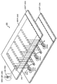
- FIG. 2 is a view showing the internal structure of the LED light emitter using RGB and IR LED according to an embodiment of the present invention.
- an LED light emitter 200 using RGB and IR LEDs may include an LED array 250, a PCB 210, a connector 220, and a cover 230. Include.
- the control unit 130 and the power supply unit 140 described with reference to FIG. 1 are equally applicable to FIG. 2, and are omitted in this drawing to avoid redundant description. 2 is for explaining the structure of the PCB 210 and the connector 220 to make the LED light emitter 200 using the RGB and IR LED to be in close contact with the body parts comfortably.
- the LED light emitter 200 using the RGB and IR LEDs of FIG. 2 is an LED array (eg, R, G, B, IR, RIR, BIR, RG) consisting of R, G, B, IR, or a combination thereof. LED combinations of RGB, RGBIR, Certainly are arranged on the plurality of narrow and long PCBs 210.
- LED array eg, R, G, B, IR, RIR, BIR, RG
- Each of the PCBs 210 is arranged in a row with a plurality of LEDs 250 including two or more of a red LED, a green LED, a blue LED, and an infrared LED.
- the combination of each of the LEDs 250 may vary depending on the embodiment.
- Each of the PCBs 220 may have a width for arranging the LEDs 250 in a line, and each of the PCBs 220 may have an interior (that is, an upper plate portion 232 and a lower plate portion 234) of the cover portion 230. ) May be arranged in parallel (see FIG. 2). That is, by applying a structure in which several LEDs 250 are arranged in a row by narrowing and lengthening the PCBs 220, the LED light emitter 200 may have a structure that can be easily folded.
- the narrow width of the PCBs 210 allows the user of the LED light emitter 200 to comfortably wrap the body part.
- the PCBs 220 may use a flexible substrate to further increase wearability of body parts.
- the LEDs are arranged on the narrow long PCBs 210 (for example, a structure in which 10 LEDs are soldered in series on a PCB having a width of 3 mm and a length of 100 mm), and the narrow long PCBs 210 are connected to the connector. 220 may be connected.
- the connector 220 is disposed on each of the plurality of substrates to electrically connect the plurality of substrates.
- the connection method using the connector 220 may have various methods according to the embodiment.
- two PCBs 210 are illustrated as being connected by the connector 220, but are not necessarily limited thereto.
- all PCBs 210 may be entirely connected by the connector 220.
- three PCBs 210 may be connected by the connector 220.
- Each connector 220 receives power supplied by a controller (not shown) and supplies the power to the LEDs 250 located on the PCBs 210.
- the PCBs 220 connected to the connector 220 are wrapped by a coating 230 such as a soft cloth or a sponge.
- the cladding 230 surrounds the PCBs 210 and the connectors 220, and a plurality of holes are formed to allow light emitted from the LEDs 250 to be emitted to the outside. It consists of a soft material that allows it to be wrapped.
- the coating part 230 may be made of, for example, a cloth, a sponge, a fabric, a leather, or the like.
- the portion where the LEDs 250 are located is configured to open to the outside through the holes formed in the upper plate portion 232. Meanwhile, the LEDs 250 exposed to the outside through the holes may be molded by epoxy in the upper plate 232 (260).
- a controller controls the on / off frequency, driving current, or driving time of the LEDs 250 arranged on the PCBs 210 through the connectors 220.
- the controller may simultaneously control all of the LEDs 250 arranged on the PCBs 210 at the same time, or may independently control the LEDs 250 arranged on the PCBs 210 for each PCB.
- the LEDs may be controlled independently or may be controlled independently of all the LEDs 250 regardless of the PCB position. For example, if the control unit independently controls the LEDs 250 per PCB, the control unit turns on the LEDs located on one PCB and then selects the LEDs located on the adjacent PCB after a predetermined time. It can be turned on.
- a controller may drive each of the RGB and IR LEDs, control the on / off, allow the drive to be driven with an arbitrary on / off frequency, or adjust the driving time.
- the LED current can also be regulated while driving.
- the power supply unit (not shown) supplies DC power to drive the LEDs 250 to the control unit (not shown).
- the power supply (not shown) can be, for example, an adapter, a battery, or a cigar jack for a vehicle.
- the LED light emitter 200 using the RGB and IR LED of Figure 2 is a structure that can comfortably wrap the portion of the wrist, cuffs, knee joints and the like to increase the ease of use.
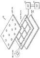
- FIG 3 is a view showing the internal structure of the LED light emitter using RGB and IR LED according to another embodiment of the present invention.
- the LED light emitter 300 using RGB and IR LEDs attaches a flat LED 360 to a flexible PCB 310 and a flat LED ( Holes are formed in the upper plate part 320 of the coating part so that light emitted from the 360 may be emitted to the outside.
- the flexible substrate 310 is arranged such that flat LEDs 360 including two or more of red LEDs, green LEDs, blue LEDs, and infrared LEDs are electrically connected.
- the combination method of the flat LEDs 360 may vary depending on the embodiment. Due to the structural characteristics of the flexible substrate 310 and the geometric characteristics of the flat LEDs 360, it is possible to form a structure that can comfortably wrap body parts such as a wrist, a wrist, a knee joint, and the like.
- the cover parts 320 and 330 may include an upper plate 320 and a lower plate 330 to surround the flexible substrate 310, and the upper plate 320 may emit light emitted from the flat LEDs 360 to the outside. A plurality of holes are formed to make.
- the cover 320, 330 is made of a soft material to wrap the body part.
- the controller 340 may control on / off frequency, driving current, or driving time of the flat LEDs 360 arranged on the flexible substrate 310.
- the power supply unit 350 supplies DC power to drive the flat LEDs 360 to the control unit 340.
- the LED light emitter using RGB and IR LED according to another embodiment of the present invention, there is a method of making the width and length of the PCB the same and make a small shape, and connecting them to the connector (not shown) ).
- the LED light emitter includes a plurality of small substrates, a plurality of connectors, a cover, a controller, and a power supply.
- the plurality of small substrates may each have at least one or more of a red LED, a green LED, a blue LED, and an infrared LED, and may have the same or different widths and lengths. Specifically, at least one or more of the red LED, the green LED, the blue LED, and the infrared LED are arranged and a plurality of small substrates having the same width and length are disposed between the lower plate and the upper plate of the coating unit.
- a connector is disposed on each of the plurality of small substrates to electrically connect the plurality of small substrates. The connectors are disposed on each of the plurality of small substrates to electrically connect the plurality of small substrates.
- a sheath (not shown) surrounds the plurality of small substrates and the plurality of connectors, and a plurality of holes are formed to allow light emitted from the LEDs arranged on the plurality of small substrates to be emitted to the outside. It may be made of a soft material that allows the area to be wrapped.
- a controller (not shown) controls at least one or more of on-off frequency, driving current, and driving time of the LEDs arranged on the plurality of small substrates through the plurality of connectors.
- the power supply unit (not shown) supplies a DC power supply to drive the LEDs arranged on the plurality of small substrates to the control unit.
Abstract
The present invention relates to an LED light emitter, comprising: a plurality of substrates on which a plurality of LEDs, which comprise at least two from a red (R) LED, a green (G) LED, a blue (B) LED, and an infrared (IR) LED, are formed in a line; a plurality of connectors, which are arranged on each of the plurality of substrates, for electrically connecting the plurality of substrates; a covering portion, which covers the plurality of substrates and the plurality of connectors, is provided with a plurality of holes for radiating to the exterior light that is emitted from the plurality of LEDs, and which comprises a soft material for covering a body part; a controller portion for controlling at least one of an on/off frequency, a driving current, and a driving time of the plurality of LEDs which are arranged on the plurality of substrates, through the plurality of connectors; and a power portion for supplying DC power to the control portion for driving the plurality of LEDs, thereby aligning the plurality of substrates, which have a narrow width and a long length and on which LEDs are mounted, and wrapping same with the soft material, so that the LED light emitter easily wraps around a body part, and wearing comfort is provided when irradiating light on one body part (for example, the wrist area), thereby increasing convenience of use, as well as effectively activating metabolism of the body and mitigating pain by conveniently absorbing light having various wavelengths into the body part.
Description
본 발명은 RGB 및 IR LED를 이용한 LED 빛 방출기에 관한 것으로, 더욱 상세하게는 R(Red)/G(Green)/B(Blue)/IR(Infra Red) LED로부터 발생되는 다양한 파장의 빛을 통증이 있는 신체 일 부위에 비춰주고 흡수되도록 하여 신진대사를 활발하게 하고 신체부위의 통증을 완화시키기 위한 RGB 및 IR LED를 이용한 LED 빛 방출기에 관한 것이다.The present invention relates to an LED light emitter using RGB and IR LEDs, and more particularly to light of various wavelengths generated from R (Red) / G (Green) / B (Blue) / IR (Infra Red) LEDs. The present invention relates to an LED light emitter using RGB and IR LEDs to stimulate metabolism and relieve pain in the body part by illuminating and absorbing a part of the body.
인체에 가시광선이나 적외선이 흡수되면, 광학 작용에 의해 ATP가 생성되어 신진대사가 활발하게 되고 인체의 통증이 완화될 수 있다. 따라서, 인체 세포를 손상시키지 않을 정도로 낮은 에너지를 가진 가시광선이나 적외선을 이용하여 각종 통증을 완화시키는 광 치료법이 폭넓게 이용되기 시작하고 있다.When visible light or infrared light is absorbed by the human body, ATP is generated by optical action, thereby promoting metabolism and relieving pain in the human body. Accordingly, phototherapy has been widely used to alleviate various pains by using visible or infrared light having energy low enough to not damage human cells.
그러나, 종래의 광 치료기는, 단색(예를 들어, 레드)의 빛만을 사용하여 충분한 통증 완화 효과를 거두지 못하였고, 또한, LED를 감싸는 구조의 문제로 인해 착용감이 불편하여 사용하는데 많은 제한이 있었다. 또한, 종래의 광 치료기는, 손목, 팔목, 무릎 관절 등의 신체 일부위를 편안하게 감싸는 것이 불가능한 구조를 가지는 문제점이 있었다.However, the conventional phototherapy device does not have sufficient pain relief effect using only monochromatic (eg, red) light, and also has many limitations due to the inconvenience of wearing due to the problem of the structure surrounding the LED. . In addition, the conventional phototherapy device has a problem in that it is impossible to comfortably wrap a part of the body, such as wrist, wrist, knee joint, and the like.
본 발명이 해결하고자 하는 기술적 과제는, R, G, B, IR (RGBIR) LED 또는 이들의 조합으로 이루어지는 LED 어레이로부터 방출되는 빛이 인체에 용이하게 흡수 될 수 있도록 하는 구조를 가진 RGB 및 IR LED를 이용한 LED 빛 방출기를 제공하는 것에 있다.The technical problem to be solved by the present invention, RGB, IR LED having a structure so that light emitted from the LED array consisting of R, G, B, IR (RGBIR) LED or a combination thereof can be easily absorbed by the human body It is to provide an LED light emitter using.
또한, 본 발명이 해결하고자 하는 기술적 과제는, RGBIR을 방출하는 LED 어레이의 구동 시간 및 구동 전류 등을 조절할 수 있도록 하는 RGB 및 IR LED를 이용한 LED 빛 방출기를 제공하는 것에 있다.In addition, the technical problem to be solved by the present invention is to provide an LED light emitter using RGB and IR LED to adjust the driving time and driving current of the LED array emitting RGBIR.
또한, 본 발명이 해결하고자 하는 기술적 과제는, LED 어레이로부터 발생되는 빛이 인체에 효과적으로 흡수할 수 있도록, 손목 또는 팔목 등에 쉽게 둘러쌀 수 있도록 하는 구조를 가진 RGB 및 IR LED를 이용한 LED 빛 방출기를 제공하는 것에 있다.In addition, the technical problem to be solved by the present invention, LED light emitter using an RGB and IR LED having a structure that can be easily wrapped around the wrist or wrist so that the light generated from the LED array can be effectively absorbed by the human body It is to offer.
본 발명의 일 실시예에 따르면, RGBIR LED 어레이를 이용하여 다양한 파장의 빛을 신체의 부위에 조사하고 LED 어레이의 온/오프를 위한 펄스 구동 주파수를 가변 할 수 있도록 하며 LED 어레이를 감싸는 재료를 부드러운 재료를 사용함으로써, LED 어레이로부터 방출되는 빛이 인체에 용이하게 흡수 될 수 있도록 하는 효과가 있다.According to an embodiment of the present invention, the RGBIR LED array is used to irradiate the body part with light of various wavelengths, to vary the pulse driving frequency for turning the LED array on and off, and to soften the material surrounding the LED array. By using the material, there is an effect that the light emitted from the LED array can be easily absorbed by the human body.
또한, 본 발명의 일 실시예에 따르면, 사람의 신체 특성 및 취향에 따라 RGBIR LED 어레이의 구동 시간 및 구동 전류를 조절할 수 있도록 함으로써, 신체 부위의 신진대사 및 통증 완화의 효과를 더욱 강화할 수 있는 효과가 있다.In addition, according to an embodiment of the present invention, by adjusting the driving time and the driving current of the RGBIR LED array according to the human body characteristics and tastes, the effect of further enhancing the effects of metabolic and pain relief of the body parts There is.
또한, 본 발명의 일 실시예에 따르면, 폭이 좁고 길이가 긴 형태의 기판들에 복수 개의 LED들을 일렬로 배열하고 기판들을 커넥터에 의해 연결시킴으로써, 손목 또는 팔목 등의 신체 부위 등에 빛을 조사할 경우에 쉽게 감싸을 수 있는 구조를 제공하는 효과가 있다.In addition, according to an embodiment of the present invention, by arranging a plurality of LEDs in a row of narrow and long boards and connecting the boards by a connector, it is possible to irradiate light to a body part such as a wrist or wrist In this case, there is an effect of providing a structure that can be easily wrapped.
도 1은 본 발명에 따른 RGB 및 IR LED를 이용한 LED 빛 방출기의 외형을 도시한 예시 도면이다.1 is an exemplary view showing the appearance of an LED light emitter using RGB and IR LEDs according to the present invention.
도 2는 본 발명의 일 실시예에 따른 RGB 및 IR LED를 이용한 LED 빛 방출기의 내부 구조를 도시한 도면이다.2 is a view showing the internal structure of the LED light emitter using RGB and IR LED according to an embodiment of the present invention.
도 3은 본 발명의 다른 실시예에 따른 RGB 및 IR LED를 이용한 LED 빛 방출기의 내부 구조를 도시한 도면이다.3 is a view showing the internal structure of the LED light emitter using RGB and IR LED according to another embodiment of the present invention.
본 발명의 일 실시예에 따른 RGB 및 IR LED를 이용한 LED 빛 방출기는, 레드 LED, 그린 LED, 블루 LED, 및 적외선 LED 중 2 이상을 포함하는 복수 개의 LED들이 일렬로 배열되어 있는 복수 개의 기판들; 상기 복수 개의 기판들의 각각에 배치되어, 상기 복수 개의 기판들을 전기적으로 연결하기 위한 복수 개의 커넥터들; 상기 복수 개의 기판들 및 상기 복수 개의 커넥터들을 둘러싸고, 상기 복수 개의 LED들에서 방출되는 빛이 외부로 발산될 수 있도록 하는 복수 개의 홀들(holes)이 형성되며, 신체 부위를 감쌀 수 있도록 하는 부드러운 재료로 구성되는 피복부; 상기 복수 개의 커넥터들을 통하여 상기 복수 개의 기판들에 배열된 상기 복수 개의 LED들의 온 오프 주파수, 구동 전류, 및 구동 시간 중 적어도 하나 이상을 제어하기 위한 제어부; 및 상기 제어부로 상기 복수 개의 LED들을 구동하기 위한 직류 전원을 공급하는 전원부를 포함하는 것을 특징으로 한다.LED light emitter using RGB and IR LED according to an embodiment of the present invention, a plurality of substrates are arranged in a line of a plurality of LEDs including two or more of red LED, green LED, blue LED, and infrared LED ; A plurality of connectors disposed on each of the plurality of substrates to electrically connect the plurality of substrates; Surrounding the plurality of substrates and the plurality of connectors, a plurality of holes (holes) are formed to allow the light emitted from the plurality of LEDs to be emitted to the outside, it is made of a soft material to cover the body part A coating part configured; A controller for controlling at least one of an on-off frequency, a driving current, and a driving time of the plurality of LEDs arranged on the plurality of substrates through the plurality of connectors; And a power supply unit supplying DC power to drive the plurality of LEDs to the controller.
상기 제어부는, 상기 복수 개의 기판들에 배열되어 있는 모든 LED들을 전체적으로 제어하거나, 기판 별로 독립적으로 제어하거나, 또는 LED 별로 독립적으로 제어할 수 있다.The controller may control all of the LEDs arranged on the plurality of substrates as a whole, independently control for each substrate, or independently control for each LED.
상기 피복부는, 천, 스폰지, 직물, 또는 피혁으로 구성될 수 있다.The coating may be made of cloth, sponge, fabric, or leather.
상기 전원부는, 어댑터, 배터리, 또는 차량용 시거잭일 수 있다.The power supply unit may be an adapter, a battery, or a vehicle cigar jack.
상기 복수 개의 기판들은, 각각 상기 복수 개의 LED들을 일렬로 배열하기 위한 폭을 가지며, 상기 피복부의 사이에서 병렬로 배열될 수 있다.The plurality of substrates, each having a width for arranging the plurality of LEDs in a row, may be arranged in parallel between the coating portions.
상기 복수 개의 기판들의 각각은 유연성(flexible) 기판일 수 있다.Each of the plurality of substrates may be a flexible substrate.
또한, 상술한 기술적 과제를 해결하기 위하여, 본 발명의 다른 실시예에 따른 RGB 및 IR LED를 이용한 LED 빛 방출기는, 레드 LED, 그린 LED, 블루 LED, 및 적외선 LED 중 2 이상을 포함하는 복수 개의 플랫 LED들이 배열되어 있는 유연성 기판; 상기 유연성 기판 상에 배치되어, 상기 플랫 LED들을 전기적으로 연결하기 위한 복수 개의 커넥터들; 상기 유연성 기판 및 상기 복수 개의 커넥터들을 둘러싸고, 상기 복수 개의 플랫 LED들에서 방출되는 빛이 외부로 발산될 수 있도록 하는 복수 개의 홀들(holes)이 형성되며, 신체 부위를 감쌀 수 있도록 하는 부드러운 재료로 구성되는 피복부; 상기 복수 개의 커넥터들을 통하여 상기 유연성 기판에 배열된 상기 복수 개의 플랫 LED들의 온 오프 주파수, 구동 전류, 및 구동 시간 중 적어도 하나 이상을 제어하기 위한 제어부; 및 상기 제어부로 상기 복수 개의 플랫 LED들을 구동하기 위한 직류 전원을 공급하는 전원부를 포함하는 것을 특징으로 한다.In addition, in order to solve the above technical problem, LED light emitter using RGB and IR LED according to another embodiment of the present invention, a plurality of red LED, green LED, blue LED, and infrared LED including a plurality of A flexible substrate on which flat LEDs are arranged; A plurality of connectors disposed on the flexible substrate for electrically connecting the flat LEDs; A plurality of holes are formed surrounding the flexible substrate and the plurality of connectors to allow light emitted from the plurality of flat LEDs to be emitted to the outside, and is formed of a soft material to cover a body part. Coated part; A controller for controlling at least one of an on-off frequency, a driving current, and a driving time of the plurality of flat LEDs arranged on the flexible substrate through the plurality of connectors; And a power supply unit supplying DC power to drive the plurality of flat LEDs to the controller.
또한, 상술한 기술적 과제를 해결하기 위하여, 본 발명의 다른 실시예에 따른 RGB 및 IR LED를 이용한 LED 빛 방출기는, 레드 LED, 그린 LED, 블루 LED, 및 적외선 LED 중 적어도 하나 이상이 배열되고, 동일하거나 또는 상이한 폭과 길이를 가지는 복수 개의 소형 기판들; 상기 복수 개의 소형 기판들의 각각에 배치되어, 상기 복수 개의 소형 기판들을 전기적으로 연결하기 위한 복수 개의 커넥터들; 상기 복수 개의 소형 기판들 및 상기 복수 개의 커넥터들을 둘러싸고, 상기 복수 개의 소형 기판들에 배열된 LED들에서 방출되는 빛이 외부로 발산될 수 있도록 하는 복수 개의 홀들(holes)이 형성되며, 신체 부위를 감쌀 수 있도록 하는 부드러운 재료로 구성되는 피복부; 상기 복수 개의 커넥터들을 통하여 상기 복수 개의 소형 기판들에 배열된 LED들의 온 오프 주파수, 구동 전류, 및 구동 시간 중 적어도 하나 이상을 제어하기 위한 제어부; 및 상기 제어부로 상기 복수 개의 소형 기판들에 배열된 LED들을 구동하기 위한 직류 전원을 공급하는 전원부를 포함하는 것을 특징으로 한다.In addition, in order to solve the above technical problem, LED light emitter using RGB and IR LED according to another embodiment of the present invention, at least one or more of the red LED, green LED, blue LED, and infrared LED is arranged, A plurality of small substrates having the same or different widths and lengths; A plurality of connectors disposed on each of the plurality of small substrates to electrically connect the plurality of small substrates; A plurality of holes are formed surrounding the plurality of small substrates and the plurality of connectors to allow light emitted from the LEDs arranged on the plurality of small substrates to be emitted to the outside. A coating part made of a soft material to be wrapped; A controller for controlling at least one of on / off frequency, driving current, and driving time of the LEDs arranged on the plurality of small substrates through the plurality of connectors; And a power supply unit supplying DC power to drive the LEDs arranged on the plurality of small substrates to the controller.
이하, 첨부한 도면을 참조하여 본 발명의 바람직한 실시예를 상세하게 설명한다.Hereinafter, exemplary embodiments of the present invention will be described in detail with reference to the accompanying drawings.
도 1은 본 발명의 일 실시예에 따른 RGB 및 IR LED를 이용한 LED 빛 방출기의 외형을 도시한 도면이다.1 is a view showing the appearance of an LED light emitter using RGB and IR LED according to an embodiment of the present invention.
도 1을 참조하면, RGB 및 IR LED를 이용한 LED 빛 방출기(100)는 R(Red) LED, G(Green) LED, B(Blue) LED, IR(Infra Red) LED, 또는 이들의 조합(이하, 'LED 어레이')을 단단한 PCB 또는 유연성 PCB에 배열하여 전기적으로 연결한 장치이다. 또한, RGB 및 IR LED를 이용한 LED 빛 방출기(100)는 장치가 신체 부위에 용이하게 밀착되도록 천 또는 스폰지 등과 같은 부드러운 재료로 둘러쌓인다. 또한, RGB 및 IR LED를 이용한 LED 빛 방출기(100)는 LED 어레이(110)를 온/오프하거나, 동작 중의 온/오프 주파수를 제어하거나, 또는 LED 어레이의 구동 전류 및 구동 시간을 제어한다.Referring to FIG. 1, an LED light emitter 100 using RGB and IR LEDs may include an R (Red) LED, a G (Green) LED, a B (Blue) LED, an IR (Infra Red) LED, or a combination thereof. , An 'LED array' is an electrically connected device arranged on a rigid or flexible PCB. In addition, the LED light emitter 100 using RGB and IR LEDs is surrounded by a soft material, such as a cloth or sponge, so that the device is easily adhered to the body part. In addition, the LED light emitter 100 using the RGB and IR LEDs turn on / off the LED array 110, control the on / off frequency during operation, or control the drive current and drive time of the LED array.
상술한 동작을 수행하기 위하여, RGB 및 IR LED를 이용한 LED 빛 방출기(100)는 LED 어레이(110), 피복부(120), 제어부(130), 및 전원부(140)를 포함한다. 피복부(120)의 내부에 배치되는 PCB 또는 커넥터의 구체적인 구조는 도 2 및 도 3을 참조하여 후술된다.In order to perform the above operation, the LED light emitter 100 using RGB and IR LEDs includes an LED array 110, a cover 120, a controller 130, and a power supply 140. A detailed structure of the PCB or the connector disposed inside the cover part 120 will be described later with reference to FIGS. 2 and 3.
LED 어레이(110)는 레드(Red) LED(102), 그린(Green) LED(104), 블루(Blue) LED(106), 적외선(IR:Infrared) LED(108), 또는 이들의 조합(예를 들어, R, G, B, IR, RIR, BIR, RG, RGB, RGBIR, ... 등)이 PCB(도시되지 않음) 상에 소정 간격으로 배열된 것이다. 도 1의 예시에서는, R LED(102), G LED(104), B LED(106), IR LED(108)가 한 줄씩 순차적으로 배열되어 있다. LED 어레이(110)에 포함된 각 LED들은 커넥터(도시되지 않음)를 이용하여 연결될 수 있다.The LED array 110 may be a red LED 102, a green LED 104, a blue LED 106, an infrared LED 108, or a combination thereof (eg For example, R, G, B, IR, RIR, BIR, RG, RGB, RGBIR, ..., etc.) are arranged at predetermined intervals on a PCB (not shown). In the example of FIG. 1, the R LEDs 102, the G LEDs 104, the B LEDs 106, and the IR LEDs 108 are sequentially arranged line by line. Each LED included in the LED array 110 may be connected using a connector (not shown).
피복부(120)는 RGB 및 IR LED를 이용한 LED 빛 방출기(100)가 신체 부위에 편안하게 밀착되도록 하기 위하여, LED 어레이(110)가 배열되어 있는 PCB(도시되지 않음) 및 LED들을 전기적으로 연결하기 위한 커넥터(도시되지 않음)를 둘러싸고 있다. 예를 들어, 피복부(120)는 PCB와 커넥터의 상면을 커버하기 위한 상판부(122), 및 PCB와 커넥터의 하면을 커버하기 위한 하판부(124)를 포함할 수 있다. 또한, 상판부(122) 및 하판부(124)는 각각 신체 부위를 편안하게 감쌀 수 있도록 하기 위하여 부드러운 재료로 구성될 수 있다. 예를 들어, 상판부(122) 및 하판부(124)는 천, 스폰지, 직물, 또는 피혁 등으로 구성될 수 있다.The coating part 120 electrically connects the LEDs (not shown) and the LEDs on which the LED array 110 is arranged so that the LED light emitter 100 using the RGB and IR LEDs can be comfortably adhered to the body part. Surrounds a connector (not shown). For example, the cover 120 may include an upper plate 122 for covering the upper surface of the PCB and the connector, and a lower plate 124 for covering the lower surface of the PCB and the connector. In addition, the upper plate portion 122 and the lower plate portion 124 may be made of a soft material, respectively, so as to comfortably wrap the body part. For example, the upper plate 122 and the lower plate 124 may be made of cloth, sponge, fabric, leather or the like.
상판부(122)에는 LED 어레이(110)의 각 LED들에서 방출되는 빛이 외부로 발산될 수 있도록 하는 복수 개의 홀들(holes)이 형성되어 있다. 피복부(120)의 내부(즉, 상판부(122) 및 하판부(124)의 사이)에 배치된 LED 어레이(110)는 홀들을 통해서 빛을 발산할 수 있다.The upper plate 122 is formed with a plurality of holes to allow light emitted from each of the LEDs of the LED array 110 to be emitted to the outside. The LED array 110 disposed inside the coating part 120 (that is, between the upper plate part 122 and the lower plate part 124) may emit light through the holes.
또한, 상판부(122)의 모서리 쪽 하면 및 하판부(124)의 모서리 쪽 상면에는 부착천과 같은 재료가 부착되어, 상판부(122) 및 하판부(124)가 서로 접착되도록 구성될 수 있다.In addition, a material such as an attaching cloth may be attached to the bottom surface of the upper edge portion 122 and the upper surface of the edge portion of the lower plate portion 124, such that the upper plate portion 122 and the lower plate portion 124 may be bonded to each other.
제어부(130)는 피복부(120)의 내부(즉, 상판부(122) 및 하판부(124)의 사이)에 배치된 LED들의 온/오프 주파수, 구동 전류, 또는 구동 시간을 제어한다. 예를 들어, 제어부(130)는 사용자의 입력에 의해서 LED들의 온/오프를 조절하거나, 펄스 구동 주파수를 가변하여 온/오프 주파수를 가변시키거나, 구동 전류의 조절을 통해서 LED들에서 방출되는 빛의 강도를 제어하거나, 또는 구동 시간의 조절을 통해서 LED 빛 방출기(100)의 동작 시간을 조절할 수 있다.The controller 130 controls the on / off frequency, driving current, or driving time of the LEDs disposed inside the cover part 120 (ie, between the upper plate 122 and the lower plate 124). For example, the controller 130 may adjust the on / off of the LEDs by a user input, change the on / off frequency by varying the pulse driving frequency, or the light emitted from the LEDs by adjusting the driving current. The operating time of the LED light emitter 100 may be adjusted by controlling the intensity of the LED or adjusting the driving time.
전원부(140)는 제어부(130)로 LED 어레이(110)를 구동하기 위한 직류 전원을 공급한다. 예를 들어, 전원부(140)는 교류 전원을 직류 전원으로 변환하는 범용 어댑터이거나, 배터리이거나, 또는 차량 내 배터리와 연결하여 사용하기 위한 차량용 시거잭일 수도 있다. 전원부(140)에 의해 공급된 직류 전원은 제어부(130)의 제어에 따라서 LED 어레이(110)로 입력된다.The power supply unit 140 supplies DC power to drive the LED array 110 to the controller 130. For example, the power supply unit 140 may be a universal adapter for converting AC power into DC power, a battery, or a vehicle cigar jack for use in connection with a battery in a vehicle. The DC power supplied by the power supply unit 140 is input to the LED array 110 under the control of the controller 130.
도 2는 본 발명의 일 실시예에 따른 RGB 및 IR LED를 이용한 LED 빛 방출기의 내부 구조를 도시한 도면이다.2 is a view showing the internal structure of the LED light emitter using RGB and IR LED according to an embodiment of the present invention.
도 2를 참조하면, 본 발명의 일 실시예에 따른 RGB 및 IR LED를 이용한 LED 빛 방출기(200)는 LED 어레이(250), PCB(210), 커넥터(220), 및 피복부(230)를 포함한다. 도 1을 참조하여 설명된 제어부(130) 및 전원부(140)는 도 2에도 동일하게 적용되며, 중복된 설명을 피하기 위해 본 도면에서는 생략되었다. 도 2는 RGB 및 IR LED를 이용한 LED 빛 방출기(200)가 신체 부위에 편안하게 밀착되도록 하기 위한 PCB(210) 및 커넥터(220)의 구조를 중점적으로 설명하기 위한 것이다.2, an LED light emitter 200 using RGB and IR LEDs according to an embodiment of the present invention may include an LED array 250, a PCB 210, a connector 220, and a cover 230. Include. The control unit 130 and the power supply unit 140 described with reference to FIG. 1 are equally applicable to FIG. 2, and are omitted in this drawing to avoid redundant description. 2 is for explaining the structure of the PCB 210 and the connector 220 to make the LED light emitter 200 using the RGB and IR LED to be in close contact with the body parts comfortably.
도 2의 RGB 및 IR LED를 이용한 LED 빛 방출기(200)는 R, G, B, IR, 또는 이들의 조합으로 이루어진 LED 어레이(예를 들어, R, G, B, IR, RIR, BIR, RG, RGB, RGBIR, ... 등의 LED 조합)를 폭이 좁고 긴 복수 개의 PCB들(210) 위에 배열하여 구성된다.The LED light emitter 200 using the RGB and IR LEDs of FIG. 2 is an LED array (eg, R, G, B, IR, RIR, BIR, RG) consisting of R, G, B, IR, or a combination thereof. LED combinations of RGB, RGBIR, ...) are arranged on the plurality of narrow and long PCBs 210.
PCB들(210)의 각각에는 레드 LED, 그린 LED, 블루 LED, 및 적외선 LED 중 2 이상을 포함하는 복수 개의 LED들(250)이 일렬로 배열되어 있다. 각 LED들(250)의 조합 방식은 실시예에 따라 달라질 수 있다. PCB들(220) 각각은 LED들(250)을 일렬로 배열하기 위한 폭을 가질 수 있고, PCB들(220) 각각은 피복부(230)의 내부(즉, 상판부(232) 및 하판부(234)의 사이)에서 병렬로 배열될 수 있다(도 2 참조). 즉, PCB들(220)의 폭을 좁고 길게 하여 LED들(250)을 한 줄로 여러 개 배열시킨 구조를 적용함으로써, LED 빛 방출기(200)는 쉽게 접힐 수 있는 구조를 가지게 된다.Each of the PCBs 210 is arranged in a row with a plurality of LEDs 250 including two or more of a red LED, a green LED, a blue LED, and an infrared LED. The combination of each of the LEDs 250 may vary depending on the embodiment. Each of the PCBs 220 may have a width for arranging the LEDs 250 in a line, and each of the PCBs 220 may have an interior (that is, an upper plate portion 232 and a lower plate portion 234) of the cover portion 230. ) May be arranged in parallel (see FIG. 2). That is, by applying a structure in which several LEDs 250 are arranged in a row by narrowing and lengthening the PCBs 220, the LED light emitter 200 may have a structure that can be easily folded.
LED들(250)은 PCB들(210) 상에서 지지됨과 동시에, PCB들(210)의 좁은 폭은 LED 빛 방출기(200)의 사용자로 하여금 편안하게 신체 부위를 감싸을 수 있도록 한다. 다른 실시예로, PCB들(220)은 신체 부위의 착용성을 더욱 증대시키기 위하여 유연성(flexible) 기판이 사용될 수도 있다.While the LEDs 250 are supported on the PCBs 210, the narrow width of the PCBs 210 allows the user of the LED light emitter 200 to comfortably wrap the body part. In another embodiment, the PCBs 220 may use a flexible substrate to further increase wearability of body parts.
이와 같이, 좁고 긴 PCB들(210) 상에 LED들이 배열되고(예를 들어, 10개의 LED를 폭 3mm, 길이 100mm의 PCB 상에 일렬로 납땜하는 구조), 좁고 긴 PCB들(210)을 커넥터(220)를 이용하여 연결할 수 있다.As such, the LEDs are arranged on the narrow long PCBs 210 (for example, a structure in which 10 LEDs are soldered in series on a PCB having a width of 3 mm and a length of 100 mm), and the narrow long PCBs 210 are connected to the connector. 220 may be connected.
커넥터(220)는 복수 개의 기판들의 각각에 배치되어, 복수 개의 기판들을 전기적으로 연결하기 위한 것이다. 커넥터(220)를 이용한 연결 방법은 실시예에 따라서 다양한 방법이 있을 수 있다. 도 2에서는 두 개의 PCB(210)들이 커넥터(220)에 의해 연결되어 있는 것으로 도시되어 있으나, 반드시 이에 한정되는 것은 아니며, 예를 들어 모든 PCB들(210)이 커넥터(220)에 의해 전체적으로 연결될 수도 있고, 세 개의 PCB(210)들이 커넥터(220)에 의해 연결될 수도 있다. 각 커넥터(220)는 제어부(도시되지 않음)에 의해 공급되는 전원을 입력받아 PCB들(210) 상에 위치한 LED들(250)에게 공급한다.The connector 220 is disposed on each of the plurality of substrates to electrically connect the plurality of substrates. The connection method using the connector 220 may have various methods according to the embodiment. In FIG. 2, two PCBs 210 are illustrated as being connected by the connector 220, but are not necessarily limited thereto. For example, all PCBs 210 may be entirely connected by the connector 220. In addition, three PCBs 210 may be connected by the connector 220. Each connector 220 receives power supplied by a controller (not shown) and supplies the power to the LEDs 250 located on the PCBs 210.
또한, 커넥터(220)로 연결된 PCB들(220)은 부드러운 천이나 스펀지와 같은 피복부(230)에 의해 감싸진다. 피복부(230)는 PCB들(210) 및 커넥터들(220)을 둘러싸고, LED들(250)에서 방출되는 빛이 외부로 발산될 수 있도록 하는 복수 개의 홀들(holes)이 형성되며, 신체 부위를 감쌀 수 있도록 하는 부드러운 재료로 구성된다. 피복부(230)는, 예를 들어, 천, 스폰지, 직물, 또는 피혁 등으로 구성될 수 있다. 또한, LED들(250)이 위치한 부분은 상판부(232)에 형성된 홀들을 통해서 외부로 개방되도록 구성된다. 한편, 홀들을 통해 외부로 노출되는 LED들(250)은 상판부(232)에서 에폭시에 의해 몰딩될 수 있다(260).In addition, the PCBs 220 connected to the connector 220 are wrapped by a coating 230 such as a soft cloth or a sponge. The cladding 230 surrounds the PCBs 210 and the connectors 220, and a plurality of holes are formed to allow light emitted from the LEDs 250 to be emitted to the outside. It consists of a soft material that allows it to be wrapped. The coating part 230 may be made of, for example, a cloth, a sponge, a fabric, a leather, or the like. In addition, the portion where the LEDs 250 are located is configured to open to the outside through the holes formed in the upper plate portion 232. Meanwhile, the LEDs 250 exposed to the outside through the holes may be molded by epoxy in the upper plate 232 (260).
제어부(도시되지 않음)는 커넥터들(220)을 통하여 PCB들(210)에 배열된 LED들(250)의 온 오프 주파수, 구동 전류, 또는 구동 시간을 제어한다. 제어부(도시되지 않음)는 PCB들(210)에 배열되어 있는 LED들(250)의 전부를 전체적으로 동시에 제어할 수도 있고, 또는 PCB들(210)에 배열되어 있는 LED들(250)을 PCB별로 독립적으로 제어할 수도 있으며, 또는 PCB 위치와 관계없이 모든 LED들(250)을 독립적으로 제어할 수도 있다. 예를 들어, 제어부가 LED들(250)을 PCB별로 독립적으로 제어하는 경우, 제어부는 한 PCB 상에 위치한 LED들을 온(on)시키고 그리고나서 소정의 시간이 경과한 후에 인접한 PCB 상에 위치한 LED들을 온(on)시킬 수 있다.A controller (not shown) controls the on / off frequency, driving current, or driving time of the LEDs 250 arranged on the PCBs 210 through the connectors 220. The controller (not shown) may simultaneously control all of the LEDs 250 arranged on the PCBs 210 at the same time, or may independently control the LEDs 250 arranged on the PCBs 210 for each PCB. The LEDs may be controlled independently or may be controlled independently of all the LEDs 250 regardless of the PCB position. For example, if the control unit independently controls the LEDs 250 per PCB, the control unit turns on the LEDs located on one PCB and then selects the LEDs located on the adjacent PCB after a predetermined time. It can be turned on.
제어부(도시되지 않음)는 각각의 RGB 및 IR LED를 구동할 수 있고, 온/오프를 제어하거나, 구동 시에 임의의 온/오프 주파수를 가지고 구동되도록 할 수도 있으며, 구동되는 시간을 조절할 수도 있고, 구동되는 동안 LED 전류를 조절할 수도 있다.A controller (not shown) may drive each of the RGB and IR LEDs, control the on / off, allow the drive to be driven with an arbitrary on / off frequency, or adjust the driving time. The LED current can also be regulated while driving.
전원부(도시되지 않음)는 제어부(도시되지 않음)로 LED들(250)을 구동하기 위한 직류 전원을 공급한다. 전원부(도시되지 않음)는 예를 들어 어댑터, 배터리, 또는 차량용 시거잭일 수 있다.The power supply unit (not shown) supplies DC power to drive the LEDs 250 to the control unit (not shown). The power supply (not shown) can be, for example, an adapter, a battery, or a cigar jack for a vehicle.
상술한 구조에 의해서, 도 2의 RGB 및 IR LED를 이용한 LED 빛 방출기(200)는 손목, 팔목, 무릎관절 등의 부분을 편안하게 감싸을 수 있는 구조가 되어 사용 편리성을 증가시킨다.By the above-described structure, the LED light emitter 200 using the RGB and IR LED of Figure 2 is a structure that can comfortably wrap the portion of the wrist, cuffs, knee joints and the like to increase the ease of use.
도 3은 본 발명의 다른 실시예에 따른 RGB 및 IR LED를 이용한 LED 빛 방출기의 내부 구조를 도시한 도면이다.3 is a view showing the internal structure of the LED light emitter using RGB and IR LED according to another embodiment of the present invention.
도 3을 참조하면, 본 발명의 다른 실시예에 따른 RGB 및 IR LED를 이용한 LED 빛 방출기(300)는 유연성(flexible) PCB(310)에 플랫(flat) LED(360)를 붙이고, 플랫 LED(360)로부터 방출되는 빛이 외부로 발산될 수 있도록 피복부의 상판부(320)에 홀들이 형성되어 있다.Referring to FIG. 3, the LED light emitter 300 using RGB and IR LEDs according to another embodiment of the present invention attaches a flat LED 360 to a flexible PCB 310 and a flat LED ( Holes are formed in the upper plate part 320 of the coating part so that light emitted from the 360 may be emitted to the outside.
유연성 기판(310)은 레드 LED, 그린 LED, 블루 LED, 및 적외선 LED 중 2 이상을 포함하는 플랫 LED들(360)이 전기적으로 연결되도록 배열되어 있다. 플랫 LED들(360)의 조합 방법은 실시예에 따라 다양할 수 있다. 유연성 기판(310)의 구조적인 특성 및 플랫 LED들(360)의 형상적인 특성으로 인해, 손목, 팔목, 무릎 관절 등의 신체 부위를 편안하게 감싸을 수 있는 구조를 형성할 수 있다.The flexible substrate 310 is arranged such that flat LEDs 360 including two or more of red LEDs, green LEDs, blue LEDs, and infrared LEDs are electrically connected. The combination method of the flat LEDs 360 may vary depending on the embodiment. Due to the structural characteristics of the flexible substrate 310 and the geometric characteristics of the flat LEDs 360, it is possible to form a structure that can comfortably wrap body parts such as a wrist, a wrist, a knee joint, and the like.
피복부(320,330)는 유연성 기판(310)을 둘러싸기 위한 상판부(320) 및 하판부(330)로 구성되고, 상판부(320)는 플랫 LED들(360)에서 방출되는 빛이 외부로 발산될 수 있도록 하는 복수 개의 홀들(holes)이 형성된다. 또한, 피복부(320,330)는 신체 부위를 감쌀 수 있도록 하는 부드러운 재료로 구성된다.The cover parts 320 and 330 may include an upper plate 320 and a lower plate 330 to surround the flexible substrate 310, and the upper plate 320 may emit light emitted from the flat LEDs 360 to the outside. A plurality of holes are formed to make. In addition, the cover 320, 330 is made of a soft material to wrap the body part.
제어부(340)는 유연성 기판(310)에 배열된 플랫 LED들(360)의 온/오프 주파수, 구동 전류, 또는 구동 시간을 제어할 수 있다.The controller 340 may control on / off frequency, driving current, or driving time of the flat LEDs 360 arranged on the flexible substrate 310.
전원부(350)는 제어부(340)로 플랫 LED들(360)을 구동하기 위한 직류 전원을 공급한다.The power supply unit 350 supplies DC power to drive the flat LEDs 360 to the control unit 340.
한편, 본 발명의 또 다른 실시예에 따른 RGB 및 IR LED를 이용한 LED 빛 방출기의 내부 구조로서, PCB의 폭과 길이를 같게 만들고 작은 형태로 만들어, 이들을 커넥터로 연결하는 방법이 있다(도시되지 않음). 이를 위하여, LED 빛 방출기(도시되지 않음)는 복수 개의 소형 기판들, 복수 개의 커넥터들, 피복부, 제어부, 및 전원부를 포함한다.On the other hand, as an internal structure of the LED light emitter using RGB and IR LED according to another embodiment of the present invention, there is a method of making the width and length of the PCB the same and make a small shape, and connecting them to the connector (not shown) ). To this end, the LED light emitter (not shown) includes a plurality of small substrates, a plurality of connectors, a cover, a controller, and a power supply.
복수 개의 소형 기판들(도시되지 않음)은 각각 레드 LED, 그린 LED, 블루 LED, 및 적외선 LED 중 적어도 하나 이상이 배열되고, 동일하거나 또는 상이한 폭과 길이를 가질 수 있다. 구체적으로, 레드 LED, 그린 LED, 블루 LED, 및 적외선 LED 중 적어도 하나 이상이 배열되고 동일한 폭과 길이를 가지는 복수 개의 소형 기판들이 피복부의 하판부와 상판부 사이에 배치된다. 또한, 복수 개의 소형 기판들의 각각에 커넥터가 배치되어, 복수 개의 소형 기판들을 전기적으로 연결한다. 커넥터들은 복수 개의 소형 기판들의 각각에 배치되어, 복수 개의 소형 기판들을 전기적으로 연결한다.The plurality of small substrates (not shown) may each have at least one or more of a red LED, a green LED, a blue LED, and an infrared LED, and may have the same or different widths and lengths. Specifically, at least one or more of the red LED, the green LED, the blue LED, and the infrared LED are arranged and a plurality of small substrates having the same width and length are disposed between the lower plate and the upper plate of the coating unit. In addition, a connector is disposed on each of the plurality of small substrates to electrically connect the plurality of small substrates. The connectors are disposed on each of the plurality of small substrates to electrically connect the plurality of small substrates.
피복부(도시되지 않음)는 복수 개의 소형 기판들 및 복수 개의 커넥터들을 둘러싸고, 복수 개의 소형 기판들에 배열된 LED들에서 방출되는 빛이 외부로 발산될 수 있도록 하는 복수 개의 홀들이 형성되며, 신체 부위를 감쌀 수 있도록 하는 부드러운 재료로 구성될 수 있다.A sheath (not shown) surrounds the plurality of small substrates and the plurality of connectors, and a plurality of holes are formed to allow light emitted from the LEDs arranged on the plurality of small substrates to be emitted to the outside. It may be made of a soft material that allows the area to be wrapped.
제어부(도시되지 않음)는 복수 개의 커넥터들을 통하여 복수 개의 소형 기판들에 배열된 LED들의 온 오프 주파수, 구동 전류, 및 구동 시간 중 적어도 하나 이상을 제어한다.A controller (not shown) controls at least one or more of on-off frequency, driving current, and driving time of the LEDs arranged on the plurality of small substrates through the plurality of connectors.
전원부(도시되지 않음)는 제어부로 복수 개의 소형 기판들에 배열된 LED들을 구동하기 위한 직류 전원을 공급한다.The power supply unit (not shown) supplies a DC power supply to drive the LEDs arranged on the plurality of small substrates to the control unit.
이제까지 본 발명에 대하여 그 바람직한 실시예들을 중심으로 살펴보았다. 본 발명이 속하는 기술 분야에서 통상의 지식을 가진 자는 본 발명이 본 발명의 본질적인 특성에서 벗어나지 않는 범위에서 변형된 형태로 구현될 수 있음을 이해할 수 있을 것이다. 그러므로 개시된 실시 예들은 한정적인 관점이 아니라 설명적인 관점에서 고려되어야 한다. 본 발명의 범위는 전술한 설명이 아니라 특허청구범위에 나타나 있으며, 그와 동등한 범위 내에 있는 모든 차이점은 본 발명에 포함된 것으로 해석되어야 할 것이다.So far I looked at the center of the preferred embodiment for the present invention. Those skilled in the art will appreciate that the present invention can be implemented in a modified form without departing from the essential features of the present invention. Therefore, the disclosed embodiments should be considered in descriptive sense only and not for purposes of limitation. The scope of the present invention is shown in the claims rather than the foregoing description, and all differences within the scope will be construed as being included in the present invention.
Claims (8)
- 레드 LED, 그린 LED, 블루 LED, 및 적외선 LED 중 2 이상을 포함하는 복수 개의 LED들이 일렬로 배열되어 있는 복수 개의 기판들;A plurality of substrates arranged in a row with a plurality of LEDs including at least two of a red LED, a green LED, a blue LED, and an infrared LED;상기 복수 개의 기판들의 각각에 배치되어, 상기 복수 개의 기판들을 전기적으로 연결하기 위한 복수 개의 커넥터들;A plurality of connectors disposed on each of the plurality of substrates to electrically connect the plurality of substrates;상기 복수 개의 기판들 및 상기 복수 개의 커넥터들을 둘러싸고, 상기 복수 개의 LED들에서 방출되는 빛이 외부로 발산될 수 있도록 하는 복수 개의 홀들(holes)이 형성되며, 신체 부위를 감쌀 수 있도록 하는 부드러운 재료로 구성되는 피복부;Surrounding the plurality of substrates and the plurality of connectors, a plurality of holes (holes) are formed to allow the light emitted from the plurality of LEDs to be emitted to the outside, it is made of a soft material to cover the body part A coating part configured;상기 복수 개의 커넥터들을 통하여 상기 복수 개의 기판들에 배열된 상기 복수 개의 LED들의 온 오프 주파수, 구동 전류, 및 구동 시간 중 적어도 하나 이상을 제어하기 위한 제어부; 및A controller for controlling at least one of an on-off frequency, a driving current, and a driving time of the plurality of LEDs arranged on the plurality of substrates through the plurality of connectors; And상기 제어부로 상기 복수 개의 LED들을 구동하기 위한 직류 전원을 공급하는 전원부를 포함하는 것을 특징으로 하는 RGB 및 IR LED를 이용한 LED 빛 방출기.LED light emitter using RGB and IR LED, characterized in that it comprises a power supply for supplying a direct current power for driving the plurality of LEDs to the control unit.
- 제1항에 있어서,The method of claim 1,상기 제어부는, 상기 복수 개의 기판들에 배열되어 있는 모든 LED들을 전체적으로 제어하거나, 기판 별로 독립적으로 제어하거나, 또는 LED 별로 독립적으로 제어하는 것을 특징으로 하는 RGB 및 IR LED를 이용한 LED 빛 방출기.The control unit may control all LEDs arranged on the plurality of substrates as a whole, independently control for each substrate, or independently control for each LED, LED light emitter using RGB and IR LEDs.
- 제1항에 있어서,The method of claim 1,상기 피복부는, 천, 스폰지, 직물, 또는 피혁으로 구성되는 것을 특징으로 하는 RGB 및 IR LED를 이용한 LED 빛 방출기.The coating unit is an LED light emitter using RGB and IR LED, characterized in that consisting of cloth, sponge, fabric, or leather.
- 제1항에 있어서,The method of claim 1,상기 전원부는, 어댑터, 배터리, 또는 차량용 시거잭인 것을 특징으로 하는 RGB 및 IR LED를 이용한 LED 빛 방출기.The power supply unit, an LED light emitter using an RGB, IR LED, characterized in that the adapter, a battery, or a vehicle cigar jack.
- 제1항에 있어서,The method of claim 1,상기 복수 개의 기판들은, 각각 상기 복수 개의 LED들을 일렬로 배열하기 위한 폭을 가지며, 상기 피복부의 사이에서 병렬로 배열되어 있는 것을 특징으로 하는 RGB 및 IR LED를 이용한 LED 빛 방출기.The plurality of substrates, each having a width for arranging the plurality of LEDs in a line, LED light emitter using RGB and IR LED, characterized in that arranged in parallel between the covering.
- 제1항에 있어서,The method of claim 1,상기 복수 개의 기판들의 각각은 유연성(flexible) 기판인 것을 특징으로 하는 RGB 및 IR LED를 이용한 LED 빛 방출기.LED light emitter using RGB and IR LED, characterized in that each of the plurality of substrates is a flexible substrate.
- 레드 LED, 그린 LED, 블루 LED, 및 적외선 LED 중 2 이상을 포함하는 복수 개의 플랫 LED들이 서로 전기적으로 연결되도록 배열되어 있는 유연성 기판;A flexible substrate on which a plurality of flat LEDs including at least two of a red LED, a green LED, a blue LED, and an infrared LED are arranged to be electrically connected to each other;상기 유연성 기판을 둘러싸고, 상기 복수 개의 플랫 LED들에서 방출되는 빛이 외부로 발산될 수 있도록 하는 복수 개의 홀들(holes)이 형성되며, 신체 부위를 감쌀 수 있도록 하는 부드러운 재료로 구성되는 피복부;A covering part formed of a soft material surrounding the flexible substrate and having a plurality of holes formed therein to allow light emitted from the plurality of flat LEDs to be emitted to the outside;상기 유연성 기판에 배열된 상기 복수 개의 플랫 LED들의 온 오프 주파수, 구동 전류, 및 구동 시간 중 적어도 하나 이상을 제어하기 위한 제어부; 및A control unit for controlling at least one of an on-off frequency, a driving current, and a driving time of the plurality of flat LEDs arranged on the flexible substrate; And상기 제어부로 상기 복수 개의 플랫 LED들을 구동하기 위한 직류 전원을 공급하는 전원부를 포함하는 것을 특징으로 하는 RGB 및 IR LED를 이용한 LED 빛 방출기.LED light emitter using RGB and IR LED, characterized in that it comprises a power supply for supplying a direct current power for driving the plurality of flat LEDs to the control unit.
- 레드 LED, 그린 LED, 블루 LED, 및 적외선 LED 중 적어도 하나 이상이 배열되고, 동일하거나 또는 상이한 폭과 길이를 가지는 복수 개의 소형 기판들;A plurality of small substrates arranged with at least one of a red LED, a green LED, a blue LED, and an infrared LED, and having the same or different width and length;상기 복수 개의 소형 기판들의 각각에 배치되어, 상기 복수 개의 소형 기판들을 전기적으로 연결하기 위한 복수 개의 커넥터들;A plurality of connectors disposed on each of the plurality of small substrates to electrically connect the plurality of small substrates;상기 복수 개의 소형 기판들 및 상기 복수 개의 커넥터들을 둘러싸고, 상기 복수 개의 소형 기판들에 배열된 LED들에서 방출되는 빛이 외부로 발산될 수 있도록 하는 복수 개의 홀들(holes)이 형성되며, 신체 부위를 감쌀 수 있도록 하는 부드러운 재료로 구성되는 피복부;A plurality of holes are formed surrounding the plurality of small substrates and the plurality of connectors and allow light emitted from the LEDs arranged on the plurality of small substrates to be emitted to the outside. A coating part made of a soft material to be wrapped;상기 복수 개의 커넥터들을 통하여 상기 복수 개의 소형 기판들에 배열된 LED들의 온 오프 주파수, 구동 전류, 및 구동 시간 중 적어도 하나 이상을 제어하기 위한 제어부; 및A controller for controlling at least one of on / off frequency, driving current, and driving time of the LEDs arranged on the plurality of small substrates through the plurality of connectors; And상기 제어부로 상기 복수 개의 소형 기판들에 배열된 LED들을 구동하기 위한 직류 전원을 공급하는 전원부를 포함하는 것을 특징으로 하는 RGB 및 IR LED를 이용한 LED 빛 방출기.And a power supply unit for supplying a direct current power for driving the LEDs arranged on the plurality of small substrates to the control unit.
Priority Applications (1)
| Application Number | Priority Date | Filing Date | Title |
|---|---|---|---|
| PCT/KR2011/004209 WO2012169673A1 (en) | 2011-06-08 | 2011-06-08 | Led light emitter using rgb and ir led |
Applications Claiming Priority (1)
| Application Number | Priority Date | Filing Date | Title |
|---|---|---|---|
| PCT/KR2011/004209 WO2012169673A1 (en) | 2011-06-08 | 2011-06-08 | Led light emitter using rgb and ir led |
Publications (1)
| Publication Number | Publication Date |
|---|---|
| WO2012169673A1 true WO2012169673A1 (en) | 2012-12-13 |
Family
ID=47296218
Family Applications (1)
| Application Number | Title | Priority Date | Filing Date |
|---|---|---|---|
| PCT/KR2011/004209 WO2012169673A1 (en) | 2011-06-08 | 2011-06-08 | Led light emitter using rgb and ir led |
Country Status (1)
| Country | Link |
|---|---|
| WO (1) | WO2012169673A1 (en) |
Cited By (2)
| Publication number | Priority date | Publication date | Assignee | Title |
|---|---|---|---|---|
| CN103363361A (en) * | 2013-08-06 | 2013-10-23 | 敦南科技(无锡)有限公司 | Light source light emitting module |
| CN104174119A (en) * | 2014-09-19 | 2014-12-03 | 重庆海睿科技有限公司 | Multi-spectral physical therapy intelligent control method and device |
Citations (7)
| Publication number | Priority date | Publication date | Assignee | Title |
|---|---|---|---|---|
| US5800478A (en) * | 1996-03-07 | 1998-09-01 | Light Sciences Limited Partnership | Flexible microcircuits for internal light therapy |
| US20020029071A1 (en) * | 2000-03-23 | 2002-03-07 | Colin Whitehurst | Therapeutic light source and method |
| KR20020037348A (en) * | 1999-08-24 | 2002-05-18 | 토마스 에이. 러셀 | Flexible illuminators for phototherapy |
| US6743249B1 (en) * | 1997-08-25 | 2004-06-01 | Philip G. Alden | Treatment device for photodynamic therapy and method for making same |
| US20040166146A1 (en) * | 2002-06-12 | 2004-08-26 | University Of Florida | Phototherapy bandage |
| KR100839022B1 (en) * | 2007-12-10 | 2008-06-17 | 주식회사 루트로닉 | Medical led cure device radiating multi wave |
| KR20110065045A (en) * | 2009-12-09 | 2011-06-15 | (주)지엘디테크 | Apparatus for emitting led light using rgb and ir led |
-
2011
- 2011-06-08 WO PCT/KR2011/004209 patent/WO2012169673A1/en active Application Filing
Patent Citations (7)
| Publication number | Priority date | Publication date | Assignee | Title |
|---|---|---|---|---|
| US5800478A (en) * | 1996-03-07 | 1998-09-01 | Light Sciences Limited Partnership | Flexible microcircuits for internal light therapy |
| US6743249B1 (en) * | 1997-08-25 | 2004-06-01 | Philip G. Alden | Treatment device for photodynamic therapy and method for making same |
| KR20020037348A (en) * | 1999-08-24 | 2002-05-18 | 토마스 에이. 러셀 | Flexible illuminators for phototherapy |
| US20020029071A1 (en) * | 2000-03-23 | 2002-03-07 | Colin Whitehurst | Therapeutic light source and method |
| US20040166146A1 (en) * | 2002-06-12 | 2004-08-26 | University Of Florida | Phototherapy bandage |
| KR100839022B1 (en) * | 2007-12-10 | 2008-06-17 | 주식회사 루트로닉 | Medical led cure device radiating multi wave |
| KR20110065045A (en) * | 2009-12-09 | 2011-06-15 | (주)지엘디테크 | Apparatus for emitting led light using rgb and ir led |
Cited By (2)
| Publication number | Priority date | Publication date | Assignee | Title |
|---|---|---|---|---|
| CN103363361A (en) * | 2013-08-06 | 2013-10-23 | 敦南科技(无锡)有限公司 | Light source light emitting module |
| CN104174119A (en) * | 2014-09-19 | 2014-12-03 | 重庆海睿科技有限公司 | Multi-spectral physical therapy intelligent control method and device |
Similar Documents
| Publication | Publication Date | Title |
|---|---|---|
| KR101180096B1 (en) | Apparatus for emitting LED light using RGB and IR LED | |
| US6045575A (en) | Therapeutic method and internally illuminated garment for the management of disorders treatable by phototherapy | |
| WO2017200334A1 (en) | Hand skin care device | |
| US20180339157A1 (en) | Portable one-piece therapeutical apparatus with dual heating and low-frequency treatment functions | |
| US8246666B2 (en) | Phototherapy garment | |
| US8080047B2 (en) | Light therapy device | |
| US20060100675A1 (en) | Device and method for phototherapy of jaundiced infants | |
| WO2015174556A1 (en) | Medical treatment apparatus using rays of light for treatment of rhinitis or tympanitis | |
| WO2000015296A8 (en) | Conformal patch for administering light therapy to subcutaneous tumors | |
| US11452883B1 (en) | Hands-free LED device for the treatment of wrinkles, acne, or hair loss | |
| US20100106228A1 (en) | Device and method of phototherapy for jaundiced infants | |
| WO2018182141A1 (en) | Light irradiation apparatus for vagina | |
| WO2014021557A1 (en) | A nasal cavity treatment irradiation apparatus | |
| CN102470253A (en) | OLED Phototherapy device | |
| WO2021100996A1 (en) | Portable mugwort moxibustion apparatus | |
| WO2020116714A1 (en) | Abdominal belt device having mixed ems and led emission function, and method for manufacturing same | |
| WO2012169673A1 (en) | Led light emitter using rgb and ir led | |
| WO2018182142A1 (en) | Skin care apparatus | |
| KR20220024872A (en) | Adjustable Therapeutic Face Mask | |
| WO2015053550A1 (en) | Illumination chopper | |
| WO2020130453A1 (en) | Epiphyseal plate stimulation device | |
| WO2014185558A1 (en) | Therapy device for edema and neuropathy | |
| CN101837167B (en) | Phototherapy device | |
| KR20110065045A (en) | Apparatus for emitting led light using rgb and ir led | |
| WO2010128751A2 (en) | Foldable thermal therapeutic apparatus |
Legal Events
| Date | Code | Title | Description |
|---|---|---|---|
| 121 | Ep: the epo has been informed by wipo that ep was designated in this application |
Ref document number: 11867115 Country of ref document: EP Kind code of ref document: A1 |
|
| NENP | Non-entry into the national phase |
Ref country code: DE |
|
| 32PN | Ep: public notification in the ep bulletin as address of the adressee cannot be established |
Free format text: NOTING OF LOSS OF RIGHTS PURSUANT TO RULE 112(1) EPC (EPO FORM 1205A DATED 25/03/2014) |
|
| 122 | Ep: pct application non-entry in european phase |
Ref document number: 11867115 Country of ref document: EP Kind code of ref document: A1 |