WO2013055638A1 - Integrated microneedle array delivery system - Google Patents
Integrated microneedle array delivery system Download PDFInfo
- Publication number
- WO2013055638A1 WO2013055638A1 PCT/US2012/059273 US2012059273W WO2013055638A1 WO 2013055638 A1 WO2013055638 A1 WO 2013055638A1 US 2012059273 W US2012059273 W US 2012059273W WO 2013055638 A1 WO2013055638 A1 WO 2013055638A1
- Authority
- WO
- WIPO (PCT)
- Prior art keywords
- housing
- array
- skin
- carrier assembly
- stored energy
- Prior art date
Links
Classifications
-
- A—HUMAN NECESSITIES
- A61—MEDICAL OR VETERINARY SCIENCE; HYGIENE
- A61M—DEVICES FOR INTRODUCING MEDIA INTO, OR ONTO, THE BODY; DEVICES FOR TRANSDUCING BODY MEDIA OR FOR TAKING MEDIA FROM THE BODY; DEVICES FOR PRODUCING OR ENDING SLEEP OR STUPOR
- A61M37/00—Other apparatus for introducing media into the body; Percutany, i.e. introducing medicines into the body by diffusion through the skin
- A61M37/0015—Other apparatus for introducing media into the body; Percutany, i.e. introducing medicines into the body by diffusion through the skin by using microneedles
- A61M2037/0023—Drug applicators using microneedles
-
- A—HUMAN NECESSITIES
- A61—MEDICAL OR VETERINARY SCIENCE; HYGIENE
- A61M—DEVICES FOR INTRODUCING MEDIA INTO, OR ONTO, THE BODY; DEVICES FOR TRANSDUCING BODY MEDIA OR FOR TAKING MEDIA FROM THE BODY; DEVICES FOR PRODUCING OR ENDING SLEEP OR STUPOR
- A61M37/00—Other apparatus for introducing media into the body; Percutany, i.e. introducing medicines into the body by diffusion through the skin
- A61M37/0015—Other apparatus for introducing media into the body; Percutany, i.e. introducing medicines into the body by diffusion through the skin by using microneedles
- A61M2037/0046—Solid microneedles
Definitions
- stratum corneum the outermost layer of the skin.
- microneedles Devices including arrays of relatively small structures, sometimes referred to as microneedles or micro-pins, have been disclosed for use in connection with the delivery of therapeutic agents and other substances through the skin and other surfaces.
- the devices are typically pressed against the skin in an effort to pierce the stratum corneum such that the therapeutic agents and other substances can pass through that layer and into the tissues below.
- Microneedles of these devices pierce the stratum corneum upon contact, making a plurality of microscopic slits which serve as passageways through which molecules of active components can be delivered into the body.
- the microneedle device can be provided with a reservoir for temporarily retaining an active component in liquid form prior to delivering the active component through the stratum corneum.
- the microneedles can be hollow to provide a liquid flow path directly from the reservoir and through the microneedles to enable delivery of the therapeutic substance through the skin.
- active component(s) may be coated on the microneedle array and delivered directly through the skin after the stratum corneum has been punctured.
- Microneedle arrays can be used in conjunction with an applicator device capable of being used several times or single-use.
- the microneedle arrays are generally used once and then discarded.
- microneedles include the ability to effectively and consistently insert the needles to a desired depth in the skin, the ability to reliably hold the microneedles in proper contact with the skin during the period of administration, and the ability to apply consistent force for delivery.
- the present disclosure provides a low-profile system for delivering a microneedle array.
- the delivery system includes a housing that may be secured to and temporarily worn on a patient's skin.
- a carrier assembly coupled to a microneedle array is received in the housing proximate an applicator device.
- the applicator device can include an actuator and a stored energy device. While the carrier assembly is at least releasably secured to the housing, it is typically not attached or otherwise fixed to any portion of the applicator device. As such, the applicator device will not appreciably interfere with the travel of the carrier assembly after it transfers the force necessary to pierce the stratum corneum.
- the carrier assembly Since the carrier assembly is not attached to the applicator device, it is free to continue moving forward with the motion of the skin even after the applicator device recoils or moves in a direction away from the skin. This independent motion may reduce the tendency for the microneedles to stop penetrating or to be pulled out of the skin. Increased and consistent depth of penetration can result in improved delivery across the stratum corneum.
- the variability in force applied to the array may be reduced.
- increasing the amount of energy transferred to the microneedle array meant an increase in the amount of applied energy by the user or the distance the microarray traveled before reaching the skin.
- a stored energy device is configured to store a certain amount of potential energy that can be released upon transfer of a predetermined amount of activation energy to a surface of the device. By placing a stored energy device between the user-applied force and the carrier assembly, the velocity at which the array impacts the skin may be more closely regulated.
- the present disclosure provides an integrated system for delivering a microneedle array.
- the system includes a housing having a cavity therein and an applicator device coupled thereto.
- a carrier assembly coupled to solid microneedle array is received in the cavity.
- a portion of the carrier assembly is attached to the housing proximate the cavity and is in contact with a portion of the applicator. Neither the carrier nor the array is attached to the applicator device.
- the carrier assembly further includes flexible membrane having a bellowed height sufficient to place the carrier assembly proximate a surface of the stored energy device.
- the applicator device includes a bifurcating spring.
- the present disclosure also provides methods for delivering a microneedle array to the surface of the skin.
- the method includes providing a delivery system that includes a housing having a cavity therein and an applicator device coupled thereto; a carrier assembly coupled to solid microneedle array received in the cavity; a portion of the carrier assembly is attached to the housing proximate the cavity and is in contact with a portion of the applicator; and neither the carrier nor the array are attached to the applicator device.
- the method further includes placing the housing against the skin surface; and transferring an activation energy to the carrier via the applicator device, thereby driving the array and carrier towards the skin.
- activation energy refers to the minimum amount of energy required to release the potential energy stored within a stored energy device.
- application energy refers to the energy released upon activation of a stored energy device and applied to a microneedle carrier.
- array refers to the medical devices described herein that include one or more structures capable of piercing the stratum corneum to facilitate the transdermal delivery of therapeutic agents or the sampling of fluids through or to the skin.
- Microstructure refers to the specific microscopic structures associated with the array that are capable of piercing the stratum corneum to facilitate the transdermal delivery of therapeutic agents or the sampling of fluids through the skin.
- carrier assembly refers to at least a microneedle array and any structure used to couple the array to a housing.
- the carrier assembly can refer to an array, a flexible membrane, and an adhesive layer.
- the carrier assembly refers to the array and an array carrier.
- solid microneedle array means an array comprised of microneedles of any size and shape that do not have an exposed bore therethough., in contrast to hollow microneedle arrays.
- travel distance refers to the distance traveled by an element of the delivery system upon actuation.
- the travel distance for a stored energy device may be different than the travel distance for the array.
- a delivery apparatus comprising “a” stored energy device can be interpreted to comprise “one or more” stored energy devices.
- the recitations of numerical ranges by endpoints include all numbers subsumed within that range (e.g., 1 to 5 includes 1, 1.5, 2, 2.75, 3, 3.80, 4, 5, etc.).
- Figure 1 is a perspective view of a microneedle delivery system according to one embodiment of the present disclosure.
- Figure 2 is a perspective view of the microneedle delivery system of Figure 1.
- Figure 3 is an exploded view of the microneedle delivery system of Figure 1.
- Figure 4 is a cross-sectional view of the microneedle delivery system of Figure 1.
- Figures 5A-C are cross-sectional views of the delivery system of the previous figures in operation.
- Figure 6 is a perspective view of a bifurcating spring according to certain embodiments of the disclosure.
- Figure 7 is a perspective view of a bifurcating spring according to another aspect of the disclosure.
- Figure 8 is a perspective view of a microneedle delivery system according to another aspect of the disclosure.
- Figure 9 is a cross-sectional view of the delivery system of Figure 8.
- Figure 10 is a perspective view of a microneedle delivery system according to another aspect of the disclosure.
- Figure 1 1 is a cross-sectional view of the delivery system of Figure 10.
- Figures 12 is a perspective view of a perspective view of a microneedle delivery system according to yet another aspect of the disclosure.
- Figure 13 is a cross-sectional view of the delivery system of Figure 12.
- Figure 14 depicts the delivery system of Figure 12 in operation.
- a delivery system 100 includes a device housing 1 10.
- the housing 1 10 can be self-contained and compactly constructed to provide a relatively low profile and small footprint for, among other factors, ease of use and patient comfort.
- the housing 1 10 may include lower housing portion 1 12 and mating upper housing portion 1 1 1. Alternatively,
- the delivery system may include a unitary housing.
- Upper and lower housing portions 1 1 1 1 and 1 12 may be secured together by any suitable means including, but not limited to, snap-fit together or coupled by pivots, frictional interference fits, welding, heat- staking, solvent bonding, mechanical fasteners, and the like.
- Housing 1 10 may be made of suitable lightweight materials compatible for ease of patient and practitioner handling. The materials used in housing 1 10 may include, but are not limited to, plastics, metals, composite materials, and combinations thereof.
- the housing 1 10 can be made of thermoplastics such as polypropylene, polybutylene terephthalate, polystyrene, polyethylene, polythermide, polyethylene terephthalate, polystyrene, polyvinyl chloride,
- thermoplastics such as polypropylene, polybutylene terephthalate, polystyrene, polyethylene, polythermide, polyethylene terephthalate, polystyrene, polyvinyl chloride,
- polymethylmethacrylate polymethylmethacrylate, acrylonitrile -butadiene styrene, polycarbonate, and blends thereof.
- upper housing portion 1 1 1 1 may include a window 1 18 that allows a user to easily visually observe the operation of the elements within the cavity 1 16. Additionally or alternatively, the upper housing portion 1 1 1 can include transparent material to allow a user to visually inspect the application of a microneedle array.
- the housing 1 10 includes a cavity 1 16 that receives a carrier assembly 150.
- the carrier assembly 150 includes an array carrier 151 and a microneedle array 152 coupled to a surface thereof.
- the microneedle array comprises a major plane that is oriented generally parallel to a skin surface 190 (as depicted in Figure 5A) during use of the delivery system.
- Microneedle array 152 can include one or more needle or needle-like structures as well as other structures capable of piercing the stratum corneum.
- the microneedles are typically less than 900 microns, often less than 500 microns in height, and sometimes less than 300 microns in height.
- microneedles are typically more than 20 microns in height, often more than 50 microns in height, and sometimes more than 125 microns in height.
- a stored energy device 130 is received proximate to or within the cavity 1 16 near a surface of the carrier assembly 150.
- the stored energy device can also be in direct contact with a portion of the carrier assembly 150.
- the distance between the assembly 150 and the stored energy device 130 can vary, allowing the stored energy device to travel a certain distance before contacting the assembly 150.
- microneedles useful in the various embodiments of the invention may comprise any of a variety of configurations, including but not limited to those described in the following patents and patent applications.
- One embodiment for the microneedles comprises the structures disclosed in United States Patent Application Publication No. US2003/0045837.
- the disclosed microstructures in the aforementioned patent application are in the form of microneedles having tapered structures that include at least one channel formed in the outside surface of each microneedle.
- the microneedles may have bases that are elongated in one direction.
- the channels in microneedles with elongated bases may extend from one of the ends of the elongated bases towards the tips of the microneedles.
- the channels formed along the sides of the microneedles may optionally be terminated short of the tips of the microneedles.
- the microneedle arrays may also include conduit structures formed on the surface of the substrate on which the microneedle array is located.
- the channels in the microneedles may be in fluid communication with the conduit structures.
- Another embodiment for the microneedle devices comprises the structures disclosed in co-pending United States Patent Application Publication No. US2005/0261631 which describes microneedles having a truncated tapered shape and a controlled aspect ratio.
- Still another embodiment for the microneedles comprises the structures disclosed in United States Patent No. 6,091,975 (Daddona, et al.) which describes blade-like microprotrusions for piercing the skin.
- Still another embodiment for the microneedles comprises the structures disclosed in United States Patent No. 6,312,612 (Sherman, et al.) which describes tapered structures having a hollow central channel. Still another embodiment for the micro arrays comprises the structures disclosed in International Publication No.
- WO00/74766 (Garstein, et al.) which describes hollow microneedles having at least one longitudinal blade at the top surface of tip of the microneedle.
- the cavity 1 16 can be defined by cooperation of both the upper housing 1 1 1 and the lower housing 112, or may be solely contained in the lower housing 1 12.
- the minimum height of the cavity 1 16 is at least partially determined by the desired travel distance of the microneedle array 152 before reaching the skin surface and the travel distance of the stored energy device. Accordingly, the height of cavity 1 16 in some embodiments may be no greater than 2 centimeters. In other embodiments, the height of the cavity 1 16 may be no greater than 1 centimeter, in other embodiments no greater than 8 millimeters, in yet other embodiments no greater than 5 millimeters. In certain embodiments, the height of the cavity is at least 1 millimeter, in other embodiments at least 2 millimeters, in other embodiments at least 5 millimeters. Cavities less than 1 millimeter in height may not allow sufficient travel distance for the array to pierce the stratum corneum and/or may require application of greater force to the array than safe or desirable in a low-profile device.
- Lower housing portion 1 12 includes a base 1 14, which can be generally planar, and defines an opening 1 15 to the cavity 1 16.
- the base 1 14 includes an attachment surface 1 17, which at least partially envelopes the opening 1 15 and can also be generally planar.
- the attachment surface 1 17 can include an adhesive layer 160 for eventual attachment of the housing 110 to a patient's skin surface.
- Adhesive layer 160 can be a continuous coating, a patterned coating, or discrete portions of adhesive, or combinations thereof.
- a first major surface of the adhesive can be coupled to a release liner 170 (see Fig. 3) prior to use.
- the height of the housing be designed for ease of handling and operation. Accordingly, the height of the housing 1 10 may be no greater than 3 centimeters. In other embodiments, the height of the housing may be no greater than 1 centimeter, in other embodiments no greater than 5 millimeters, in other embodiments no greater than 3 millimeters. In certain embodiments, the height of the housing is at least 1.5 millimeters, in other embodiments at least 2 millimeters, in other embodiments at least 5 millimeters.
- Housings less than 1.5 millimeters in height may not allow sufficient travel distance for the array to pierce the stratum corneum and may be too difficult to handle. On the other end of the spectrum, housings greater than 3 centimeters in height can be unwieldy and difficult to maintain adherence to skin.
- the stored energy device 130 can be secured to the interior of the housing by any suitable attachment means, including but not limited to adhesives, fasteners, interference-fits, and the like.
- peripheral portions of the stored energy device 130 may be contained between the upper housing 1 1 1 and lower housing 1 12, and rested on a groove or ridge portion proximate the cavity 1 16 without any additional attachment.
- the stored energy device 130 is actuatable to apply force in a direction generally orthogonal to the attachment surface 1 17 and major plane of the array 152.
- Suitable stored energy devices include, but are not limited to, domed springs, deflected beams, coiled springs, leaf-like springs, propellant canisters, and the like. In most embodiments, a portion of the stored energy device can travel unimpeded within the housing and/or cavity to deliver the application force to the carrier assembly 150.
- the stored energy device 130 is actuatable for applying force (i.e., application energy) to carrier assembly 150, thereby accelerating at least a portion of the assembly to a velocity before impact sufficient to pierce the skin. It is desirable that a consistent, predetermined amount of force is necessary to actuate the stored energy device, thereby resulting in a consistent amount of force applied normal to the skin during actuation.
- the microneedle array 152 typically reaches a velocity before impact ranging from between about 2 and about 20 m/sec before the microneedle array impacts a patient's skin. More typically, the array strikes a patient's skin at a velocity before impact ranging from between about 4 and about 15 m/sec. In certain preferred embodiments, the velocity at impact is consistently over 10 m/sec. It can also be desirable, however, to limit the velocity to prevent or reduce the stimulation of underlying nerve tissue on or after impact.
- the stored energy device 130 is configured so that it will undergo a bifurcated (i.e., stepwise) motion in a direction generally orthogonal to the attachment surface and/or the major plane of a microneedle array.
- the stored energy device in such embodiments can be a domed, bifurcating spring as depicted in Figures 6 and 7.
- the stored energy device can also include a plurality of bifurcating springs, as depicted in Figures 9 and 1 1.
- a bifurcating spring is a spring that undergoes a shape change as a result of a predetermined force applied normal to a major plane of the spring. Using methods further described herein, it is possible to manufacture bifurcating springs that can store a greater or substantially greater amount of energy than can be comfortably applied to the delivery system by a user during use.
- the undulating spring 330 includes a generally circular central portion and one or more legs 334.
- the spring 330 can include an aperture 336 proximate the center.
- the loaded spring 330 is designed to store a certain amount of potential energy. This potential energy is converted to a kinetic energy once a predetermined amount of activation energy is transferred to the first major surface 332 of the spring 330. This results in the spring bifurcating and reaching the destabilized configuration as depicted in Figure 7.
- the release of kinetic energy occurs in a direction 338 generally orthogonal to the major plane of the spring, which results in the center of the spring traveling a certain distance between stable and destabilized states.
- the bifurcating spring 330 may release energy greater than the energy necessary to cause bifurcation (i.e., the activation energy).
- the kinetic energy i.e., application energy when transferred to a microneedle array or carrier assembly
- the application energy is 4 times greater than the activation energy, in other embodiments, at least 10 times, and in yet other embodiments at least 20 times greater than the activation energy.
- the bifurcating spring is potentially capable of releasing substantially more energy the amount of normal force applied to the skin can be minimized while generating sufficient application velocity and the user to user variability in force applied to the carrier assembly is reduced. This reduced variability can result in more consistent and repeatable microneedle penetration.
- a bifurcating spring according to the present disclosure may be created by, e.g., applying a predetermined force (i.e., load) to the center of an otherwise non-bifurcating domed spring, while supporting the periphery.
- Suitable non-bifurcating springs include but are not limited to stainless steel domed springs available from Snaptron Inc., Windsor, CO.
- the force applied to a spring surface is preferably sufficient to cause plastic deformation of at least a portion of the spring.
- a press or probe applies a displacement to a surface 332 of the spring at a constant rate. The press continues past the point of bifurcation and until the desired force has been applied after bifurcation.
- both the load applied after bifurcation and the time over which the load is applied appear to be positively correlated with the energy necessary to activate the spring, and to a lesser degree, the potential energy released on bifurcation. After a certain time, however, an increase in hold time may not amount to an appreciable increase in stored energy.
- the energy applied after activation of the spring is further influenced by, inter alia, the material of the spring, the thickness of the material, and the geometry of the dome.
- the housing 1 10 further includes an actuator 120.
- the actuator 120 cooperates with the stored energy device 130 to form an applicator device.
- the actuator 120 includes a finger engageable portion 122 that is adapted to cover actuator opening 123 formed in the upper housing portion 1 1 1.
- the actuator further includes an extended arm portion 124 that extends from finger engageable portion 122 through opening 123 and into the cavity 1 16.
- the arm portion 124 can include a wedge 126 or other protrusion.
- the actuator 120 is movable within the housing at an angle relative to the attachment surface 1 17. Movement of the wedge 126 relative to the stored energy device 130 applies a force in a direction generally orthogonal to the major plane of the array 152.
- the actuator may not actually contact the stored energy device 130, but can remove an impediment to the release of kinetic energy.
- the actuator may engage and deform a releasable retaining device that holds the stored energy device in a primed position. Deformation or displacement of the releasable retaining device may then allow the stored energy device to discharge the potential energy stored therein.
- carrier assembly 150 includes a solid microneedle array 152, an array carrier 151, and a flexible membrane 140.
- the microneedle array 152 can be attached to a first surface of array carrier 151 by any suitable attachment means.
- the attachment means is an adhesive 157, which may be in the form of a continuous coating, a patterned coating, or discrete portions of adhesive.
- the adhesive attachment is non-permanent, that is, after application of the microneedle array, the carrier may be removed from the skin surface though all or part of the array remains.
- microneedle device 152 and the array carrier 151 include snap-fit connections, hook and loop (e.g., VelcroTM) attachments, magnetic attachment, heat bonding, welding, or any other suitable conventional attachment method known to one of ordinary skill in the art.
- the microneedle array may be formed or molded as an integral portion of the array carrier 151.
- microneedle array 152 depicted in Figure 2 has a hexagonal shape, but any of a number of shapes and sizes are suitable for use with application devices of the present invention.
- At least a portion of t the array carrier 151 can be formed so as to be relatively rigid.
- Suitable materials include polymers, such as liquid crystal polymers, polypropylene, polybutylene terephthalate, polystyrene, polyethylene, polythermide, polyethylene
- the rigidity can provide support for the microneedle array and may assist in the transfer of application energy.
- Other materials are also contemplated, including metals, ceramics, and other materials that will be apparent to those skilled in the art.
- the array carrier can be comprised of the same material as the microneedles of the microneedle array.
- the carrier assembly 150 can include a flexible membrane 140 coupled to a surface of the array carrier 151 opposite the microneedle array 152 via attachment mechanism 158.
- the flexible membrane 140 includes a chamber having a bellowed height 142.
- the bellowed height 142 is preferably such that the carrier assembly 150 is retained in contact with or in close proximity to a portion of the stored energy device 130 when received in the cavity 1 16.
- the flexible membrane 140 is preferably capable of retaining the bellowed height 142 prior to the application of force to the carrier assembly 150 via the stored energy device.
- the membrane can be constructed of CoTran 9701 polyurethane film, available from 3M Company, St. Paul, MN. Other polymeric films capable of maintaining the bellowed height are also suitable for use as a membrane.
- the flexible membrane includes a material that is sterilizable and/or maintains a sterile barrier.
- the flexible membrane 140 can be vented or non- vented.
- a chamber of air may be formed between the skin surface, the adhesive 160, the membrane/array assembly, and potentially a portion of the lower housing 1 12.
- a membrane is "vented" when it includes deliberate apertures or channels to allow the flow of fluid out of the chamber.
- at least a portion of the membrane is non-vented, in that is does not include any deliberate means for fluid to flow out of the chamber.
- Non-vented membranes may surprisingly provide better depth of microneedle penetration in the skin, as well as more consistent penetration levels across the entire array.
- a non-vented membrane may allow for a carrier assembly to be provided pre-sterilized and pre-loaded with the agent intended for transdermal delivery.
- the carrier assembly 150 may be secured within the cavity 1 16 via attachment of the flexible membrane 140.
- a certain length of the flexible membrane 140 can be secured via attachment mechanism 145 to portions of the lower housing 112 proximate the opening 1 15.
- the chamber can be sized to create an interference fit with cavity 1 16, such that the carrier assembly 150 may simply be pressed into the housing.
- the carrier assembly 150 can also be coupled or releasably coupled to the stored energy device 130.
- the stored energy device 130 may include one or more apertures and array carrier 151 can include one or more elongated protrusions capable of being received in the apertures. Once so received, the protrusion may be riveted to the stored energy device 130.
- the carrier assembly 150 may be secured to the stored energy device 130 via adhesive or other attachment means described herein.
- the motion of the microneedle array is coupled to that of the spring.
- both the spring and carrier assembly will move cooperatively towards the skin surface in the direction of the applied force. Impact of the assembly at the skin surface will also cause the skin to move in the direction of the applied force.
- the spring reaches a point of maximum extension and will begin to travel away from the skin (i.e., recoil). The surface of the skin, however, may continue to move in the direction of the applied force.
- the microneedles may stop penetrating or even pull out of the skin, leading to less and/or more inconsistent depth of penetration.
- the stored energy device 130 is not attached or otherwise fixed to the carrier assembly 150. As such, following impact at the skin, the stored energy device 130 may freely recoil upwardly and vibrate without otherwise affecting the travel of the carrier assembly/microneedle array. Since the carrier assembly 150 is not attached to the stored energy device 130 after activation, it is free to continue moving forward with the motion of the skin; without regard to the recoil of the stored energy device 130. This independent motion may reduce the tendency for the microneedles to stop penetrating or to be pulled out of the skin. Increased depth and more consistent penetration of the microneedles can result in improved delivery across the stratum corneum.
- the carrier assembly 150 can also be coupled to the housing 1 10 or cavity 116 without use of a flexible membrane 140 and without attachment to the stored energy device 130.
- the array carrier can include protrusions that rest on an internal ridge or groove, providing an inference fit that allows for release of the carrier assembly upon application of minimal force.
- the delivery system 100 may be provided to a practitioner or user fully assembled and/or coated with the agent to be delivered to the skin.
- the carrier assembly is provided separately from the housing.
- the stored energy device is provided in the loaded configuration, though it is also possible for the stored energy device to be primed after receipt or shortly before use.
- the present disclosure further provides for methods of delivering a microneedle array to a patient's skin surface.
- One method of delivering a microneedle array using decoupled delivery system 100 is depicted in Figures 5A-5C.
- the attachment surface 1 17 is placed proximate a patient's skin surface 190.
- a force may be applied to finger engageable portion 122 of the actuator 120. This force is typically applied in a direction 200 that is generally parallel to major plane of array and the attachment surface 117.
- the applied force moves the wedge 126 relative to the stored energy device, resulting in the application of force orthogonal to the major plane of the stored energy device 130.
- This application of force causes a transfer of energy (i.e., activation energy) to the stored energy device 130.
- the stored energy device releases its potential energy, accelerating a portion of the device 130 towards the carrier assembly 150.
- the force required to release the potential energy is the stored energy device is no greater than 15 N, in some embodiments no greater than 8 N, and in some embodiments no greater than 5 N, and in yet other embodiments no greater than 1 N. In certain circumstances, it may be preferred that the force required be at least 2 N and no greater than 5 N. While it may be advantageous to reduce or minimize activation force, it will be appreciated by those skilled in the art that the activation force should be high enough to avoid inadvertent firing of the stored energy device before the user is ready to use the delivery system.
- the stored energy device 130 In releasing its potential energy, at least a portion of the stored energy device 130 travels in the direction of the skin surface.
- the stored energy device 130 will contact the carrier assembly 150, applying a force in a direction 220 generally orthogonal to the major plane of the microneedle array 152.
- the energy applied by the stored energy device is no greater than 0.3 J, in some embodiments no greater than 0.2 J, and in some embodiments no greater than 0.15 J, and in yet other embodiments no greater than 0.1 J.
- the energy applied by the stored energy device is at least 0.006 J, in some embodiments at least 0.01 J, and in some embodiments at least 0.05 J. In certain
- the force applied be at least 0.013 J and no greater than 0.12 J.
- This transfer of the application energy accelerates the carrier assembly 150 including the membrane 140 in the direction of the skin, with the assembly eventually emerging through opening 1 15.
- the application energy is at least twice the activation energy, in other circumstances at least 5 times the activation energy, in other embodiments at least 10 times the activation energy, in yet other embodiments at least 20 times the activation energy, and in yet other embodiments at least 30 times the activation energy.
- Figure 5B depicts the delivery system 100 at a time after the microneedle array 152 has impacted the skin.
- the motion of the stored energy device 130 slows relative to the motion of the carrier assembly 150 and a measureable gap 230 may form between them.
- this gap may form and close one or more times before the stored energy device, carrier, and skin come to rest.
- the microarray, skin, and membrane continue to move in the direction 220 of the application force. Since the motion is decoupled, however, the carrier assembly 150 is free to move with the skin until the skin's point of maximum extension.
- the membrane is capable of traveling a greater distance than the carrier assembly would travel due to the energy applied by the stored energy device 130.
- the length of membrane 140 received in the cavity 116, and the resultant bellowed height 142, can be accordingly designed to allow the membrane 140 to extend substantially beyond the attachment surface 1 17 of the housing 1 10.
- the skin and carrier assembly 150 will begin to recoil and dampen.
- the carrier assembly may come to rest within the cavity 1 16, with substantially no portion thereof, with the exception of the microneedles, emerging from opening 1 15.
- the membrane 140 does not return to its original bellowed height 142, leaving room in the cavity 116 for the "fired" stored energy device and allowing the microneedles to remain at the desired penetration depth.
- at least a portion of the array carrier 151 can emerge from the housing.
- delivery system 100 can be activated without creating a significant skin dome and without substantially stretching the skin or otherwise disturbing the surface.
- the delivery system does not create a skin dome or stretch the skin.
- a small activation force in a direction orthogonal to the skin may be necessary to activate the stored energy device, the forces generated normal to the skin surface are essentially reacted against one another within the housing 1 10. Accordingly, the force actually applied to the skin in a direction normal to the plane of the skin is zero or near zero.
- the forces generated in a direction parallel to the plane of the skin in this embodiment are at least substantially transferred to the stored energy device as the wedge 126 slides across a surface thereof.
- the efficacy of the parallel sliding motion of the actuator will likely discourage the user from pushing the device in a direction normal to the skin during activation, further increasing the consistency of application.
- an actuator movable in direction generally parallel to the attachment surface may allow the activation force of the stored energy device to be set at a higher level, while maintaining a relatively low force required to be applied by the user. This may be particularly useful, as high activation forces can limit the patient population that can operate a particular delivery system.
- the parallel motion of the actuator may further reduce the variability in velocity of the array at impact.
- Figures 8-1 1 depict additional implementations of a delivery system according to the present disclosure, particularly those featuring alternative actuators. Except as set out in the paragraphs that follow, the delivery systems 800 and 900 are substantially the same as the apparatus 100 described above and consequently a description of the similar aspects need not be repeated.
- the delivery system 800 features a rotatable actuator 820 positioned above a stored energy device 830.
- the rotatable actuator 820 rotates about an axis of rotation 821 that is generally perpendicular to the major plane of the array 852. In other embodiments not depicted herein, the actuator 820 is configured to rotate about an axis angularly offset from axis 821.
- the rotatable actuator 820 includes helical threads 823 and a graspable ridge 822 on an exterior surface thereof.
- the upper housing 81 1 includes an aperture 870 located above the cavity 816 and stored energy device 830.
- the aperture 870 has one or more side wall portions including helical grooves 873 that correspond to the helical threads on the actuator 820.
- the rotation of the actuator 820 about the axis 821 brings an engagement surface 824 closer to the stored energy device 830.
- the actuator 820 may thus be rotated by a user until the engagement surface 824 contacts the stored energy device 830, eventually resulting in application of the predetermined activation force orthogonal to the major plane of the stored energy device 830 without substantial normal force applied to the skin.
- Figure 10 and 1 1 depict a microneedle delivery system 900 featuring a different rotatable actuator.
- Actuator 920 comprises a cam rotatable about an axis 921. Rotation of the actuator 920 transfers a force orthogonal to the major plane of the stored energy device 930 and/or the microneedle array 952.
- the delivery systems 800 and 900 may also provide the potential benefits as described above, since equal and opposite forces react within the device leading to no or essentially no force being applied normal to the skin during activation.
- the delivery system 1000 includes a housing 1010 having a cavity 1016 defined therein; a stored energy device 1030 received in or proximate to the cavity; and a carrier assembly including a microneedle array 1052 coupled to an array carrier 1051.
- An upper housing portion 101 1 includes an attachment cap 1070 received in a central aperture 1019.
- the attachment cap 1070 can be secured to the upper housing via re leasable or other adhesive, interference fit, or other means known to those having skill in the art.
- Suitable materials for the attachment cap include thermoplastic elastomers, silicones, rubber, and other materials known to one skilled in the art.
- the attachment cap 1070 receives the distal end of an elongated arm portion 1053 of the array carrier 1051.
- the end of the elongated arm portion is press fit into aperture 1019 without an attachment cap 1070.
- the arm portion 1053 also extends through an aperture in the center of stored energy device 1030.
- the arm portion 1053 is designed so that it may be press fit into the attachment cap 1070, while not engaging the periphery of the stored energy device aperture 1032 (i.e., the dimension of the aperture are greater than those of the distal end of the arm portion 1053).
- the proximal end of the arm portion 1053 may be configured for an interference fit with the aperture 1032, obviating the need for the attachment cap.
- the attachment cap and an interference fit between carrier and stored energy device can be used.
- An actuator 1020 includes one or more posts 1022 extending from a generally planar base 1021.
- the posts 1022 extend through apertures 1013 in the upper housing into the cavity 1016 proximate to or in contact with the stored energy device 1030.
- the base 1021 also includes a center pedestal 1024 designed to engage attachment cap 1070 and/or arm portion 1053.
- the actuator 1020 may be provided already received housing 1010 or as a separate component.
- One potential method of using the delivery system 1000 is depicted in Figure 14. A user places actuator 1020 within the apertures in upper housing 101 1. A force in a direction 1080 normal to the base 1021 and the attachment surface 1017 is then applied.
- the center pedestal 1024 pushes the attachment cap 1070 down to a point where it releases from the upper housing 101 1 and is free to move independently of the housing 1010.
- the posts 1022 then engage the stored energy device 1030, transferring the activation energy thereto.
- the length of the posts 1022 can be designed so that the attachment cap 1070 (or arm portion 1053) is released first, followed by transfer of energy to the stored energy device 1030.
- the attachment cap 1070 or arm portion 1053 is released and the stored energy device 1030 is activated at essentially the same time.
- the application energy transferred to the carrier assembly is sufficient to dislodge the arm portion 1053 from the attachment cap 1070 or the attachment cap 1070 from the housing.
- portions of the attachment cap 1070 can expand upon application of pressure via the pedestal 1024, releasing the arm portion 1053 while the attachment cap 1070 remains essentially in place.
- the stored energy device 1030 will contact the carrier assembly, applying a force in a direction 1080 generally orthogonal to the major plane of the microneedle array 1052. This transfer of the application energy accelerates the carrier assembly in the direction of the skin, with the assembly eventually emerging through opening on the bottom of housing 1010.
- the central pedestal 1024 may continue to push the arm portion 1053 towards the skin, potentially resulting in increased penetration depth.
- the geometry of the actuator 1020 can be adjusted such that the bottom face of the base 1021 is nearly in contact with the top surface of the upper housing at the time the stored energy device is actuated. In such an embodiment, the total distance that the housing 1010 can rebound away from the skin is limited due to the presence of a user's finger pushing down on the actuator 1020.
- the actuator 1020 can be designed to provide clearance between the bottom surface of the base 1021 and the top of the upper housing at the time of actuation, which would allow the housing 1010 to move a certain distance away from the skin as the stored energy device 1030 releases its potential energy.
- Microneedle arrays suitable for use in the present disclosure may be used to deliver drugs (including any pharmacological agent or agents) through the skin in a variation on transdermal delivery, or to the skin for intradermal or topical treatment, such as vaccination.
- drugs that are of a large molecular weight may be delivered
- Microneedle arrays suitable for use in the present delivery systems have utility for the delivery of large molecules that are ordinarily difficult to deliver by passive transdermal delivery. Examples of such large molecules include proteins, peptides, nucleotide sequences, monoclonal antibodies, DNA vaccines, polysaccharides, such as heparin, and antibiotics, such as ceftriaxone.
- microneedle arrays suitable for use in the present invention may have utility for enhancing or allowing transdermal delivery of small molecules that are otherwise difficult or impossible to deliver by passive transdermal delivery.
- molecules include salt forms; ionic molecules, such as bisphosphonates, preferably sodium alendronate or pamedronate; and molecules with physicochemical properties that are not conducive to passive transdermal delivery.
- microneedle arrays suitable for use in the present delivery system may have utility for enhancing delivery of molecules to the skin, such as in dermatological treatments, vaccine delivery, or in enhancing immune response of vaccine adjuvants.
- the drug may be applied to the skin (e.g., in the form of a solution that is swabbed on the skin surface or as a cream that is rubbed into the skin surface) prior to or after applying the microneedle array.
- the drug or fluid may be applied directly to the microneedles.
- the delivery system may be used for creating microprotrusions in the skin.
- the delivery systems may be used for immediate delivery, that is where they are applied and immediately removed from the application site, or they may be left in place for an extended time, which may range from a few minutes to as long as 1 week.
- an extended time of delivery may from 1 to 30 minutes to allow for more complete delivery of a drug than can be obtained upon application and immediate removal.
- an extended time of delivery may be from 4 hours to 1 week to provide for a sustained release of drug.
- Example 1 Two different fully assembled delivery systems were evaluated.
- Example 2 a decoupled delivery system of the design described in Figures 1 -5A-C and containing one spring was used.
- Example 2 a decoupled delivery system of the design described in Figures 12- 14 and containing three springs was used.
- the housing components of the delivery systems were fabricated from ACCURA60 plastic (3D Systems, Rock Hill, SC) using a stereolithographic process.
- the external housing dimensions for Example 1 were 34.0 mm (diameter) by 9.4 mm (overall height).
- the opening in the housing for the array was 16.0 mm in diameter.
- Example 2 The external housing dimensions for Example 2 were 27.0 mm (diameter) by 8.0 mm (overall height excluding the actuator component). The opening in the housing for the array was 14.0 mm in diameter.
- the bifurcated springs were four-legged domed springs (Snaptron, Windsor, CO) prepared from 301 full-hard stainless steel. As depicted in Figure 6, the springs had a circular shape with four equally spaced and sized cut-out sections that were shaped as continuous arcs.
- the diameter (LI) of the springs was 20.2 mm.
- Each of the four leg regions formed by the cut-outs was 4.4 mm as measured along the outer edge of the leg (L2).
- the distance across and through the center of the springs at the narrowest point was 15.0 mm (L3).
- a 3.2 mm diameter hole was positioned in the center of the springs.
- the height of the domed springs before bifurcation and conditioning was 2.3 mm.
- the stock thickness of the domed springs before forming was 0.20 mm.
- the diameter (LI) of the springs was 20.4 mm.
- Each of the four leg regions formed by the cut-outs was 3.9 mm as measured along the outer edge of the leg (L2).
- the distance across and through the center of the springs at the narrowest point was 13.7 mm (L3).
- a 3.2 mm diameter hole was positioned in the center of the springs.
- the height of the domed springs before bifurcation and conditioning was 1.8 mm.
- the stock thickness of the domed springs before forming was 0.18 mm.
- the springs of Examples 1 and 2 were bifurcated and the activation energy level was set by the following spring conditioning process.
- the center of the single spring of Example 1 was displaced from its resting geometry at a rate of 0.1 mm/second through a bifurcation point until reaching a maximum displacement force of 3000 g after bifurcation.
- the spring was held at the maximum displacement force for 30 seconds before releasing the applied load.
- the targeted stored potential energy of the 1 -spring system was 0.059 J.
- the center of each spring was displaced from its resting geometry at a rate of 0.1 mm/sec through a bifurcation point until reaching a maximum displacement force of 1500 g after bifurcation.
- Each spring was held at the maximum displacement force for 30 seconds before releasing the applied load.
- the targeted stored potential energy of the 3-spring system was 0.048 J.
- the spring conditioning procedures were designed to provide a spring or set of springs that produced a total targeted activation force of 350-400 g.
- the flexible membrane in the delivery system of Example 1 was about 25.2 mm in diameter and was constructed from CoTran 9701 polyurethane film (3M Company, St. Paul, MN) having an initial film thickness of 2 mil. A film stretching procedure was used to create the bellowed membrane.
- the membrane was attached to both the lower housing (of an unassembled device) and the array carrier using a continuous coating of 3M Double Coated Medical Tape 1513 (3M Company, St. Paul, MN).
- the lower housing was simply supported at its perimeter and the membrane film was stretched by displacing the array carrier a distance of 12 mm at a rate of 0.5 mm/second and holding at its maximum displacement for 30 seconds.
- the assembly of the delivery system was completed by attaching the remaining components and positioning the now bellowed membrane with the attached array carrier in the cavity of the housing.
- the microneedle array was molded as an integral portion of the array carrier using either LEXAN HPSIR- 1125 polycarbonate (PC) (GE Plastics, Pittsfield, MA) or VECTRA MT 1300 thermoplastic liquid crystal polymer (LCP) (Ticona Engineering Polymers, Florence, KY).
- the microneedle array featured four-sided pyramidal shaped microneedles having heights of about 500 microns. Each microneedle was formed having a base width of about 167 microns and a tip width of about 10 microns.
- the microneedles were oriented in an octagon shaped pattern of about 471 microneedles with equal spacing between individual microneedles of about 550 microns (as measured from tip to tip).
- the array carrier featured a circular shaped base with a diameter of 13.4 mm.
- the microneedle array was molded as an integral portion of the array carrier using LEXAN HPSIR- 1 125 polycarbonate (PC).
- the PC microneedle array featured four-sided pyramidal shaped microneedles having heights of about 250 microns. Each microneedle was formed having a base width of about 83 microns and a tip width of about 10 microns.
- the microneedles were oriented in an octagon shaped pattern of about 1288 microneedles with equal spacing between individual microneedles of about 275 microns (as measured from tip to tip).
- the array carrier featured a circular shaped base with a diameter of 12.7 mm.
- the array carrier also included an elongated arm 2.8 mm in diameter and 6.3 mm in length.
- the final resting position of the base of the microneedle array extended beyond the base of the lower housing by a distance of 0.1 1 mm for Example 1, and a distance of 0.08 mm for Example 2.
- DOP depth of penetration
- microneedles of an array when applied to the skin surface of Yorkshire cross domestic pigs (Midwest Research Swine, Gibbon, MN), in vivo.
- the microneedle arrays Prior to application, the microneedle arrays were coated with Rhodamine B using a three-step coating process.
- step one the uncoated arrays were flood coated with a solution containing 50 ⁇ of 1.0 mg/ml polyvinyl alcohol (80% hydro lyzed) (Sigma- Aldrich, St. Louis, MO) and 67 ⁇ of Tween® 80 (Sigma- Aldrich, St. Louis, MO) in 90% (weight/volume) ethyl alcohol.
- the coated arrays were dried at 35 °C for 20 minutes.
- step two the arrays were flood coated with 60 ⁇ of an aqueous solution of 33.3 mg/ml aluminum potassium sulfate (Penta Manufacturing, Livingston, NJ) and then dried at 35 °C for 30 minutes.
- step three the primed arrays were flood coated with 60 ⁇ of an aqueous solution of 0.08% (weight/volume) Rhodamine B (Sigma-Aldrich, St. Louis, MO) and then dried at 35 °C for 30 minutes.
- the ham area of the pig was selected as the application site.
- the ham area was first trimmed with an electric clipper followed by shaving with a razor and shaving cream.
- the ham was then rinsed with deionized water and wiped with 70/30 isopropanol water.
- the animals were anesthetized with isoflurane gas and maintained under anesthesia throughout the experiment.
- a fully assembled delivery system as described for Example 1 was applied to the skin on the ham area of a pig with 3M Double Coated Medical Tape 1513. The delivery system was actuated, maintained on the animal for 15 minutes, and then removed.
- the depth of penetration into the pig skin was determined indirectly by measuring the distance from the tip of the microneedle to where the Rhodamine B coating was wiped or dissolved from the microneedle after application into the skin. The measurement was conducted using a Nikon LV- 100 microscope at 100X magnification (Nikon Instruments, Melville, NY) with Image Pro® Plus digital image analysis software (Media Cybernetics, Bethesda, MD). For each microneedle array type (PC or LCP), three animals were tested. The mean DOP was determined by sampling a subset of 72 microneedles from each array. Each array pattern was divided into four quadrants and relatively equal numbers of microneedles were sampled from each quadrant. In Table 1 , the results are reported from the microneedle DOP study.
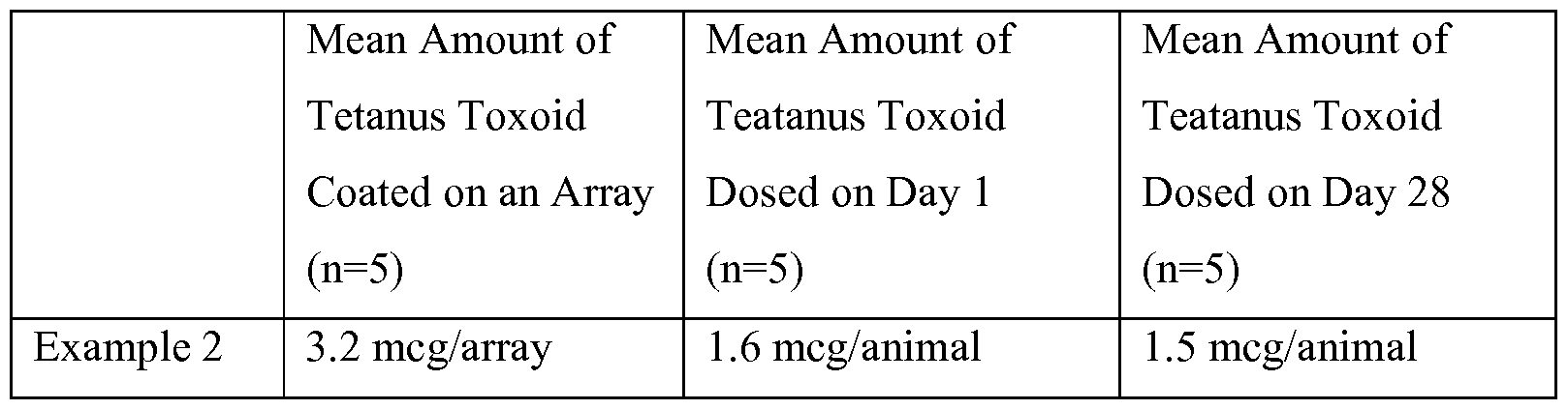
- Example 2 A fully assembled microneedle array delivery system as described in Example 2 was used in a tetanus toxoid immunization study.
- microneedle arrays described above were dip-coated (procedures to dip coating provided in United States Patent Application Publication No. US2008/0051699 (Choi, et al.)) with a formulation containing tetanus toxoid (Statens Serum Institute, Copenhagen, Denmark), sucrose (30%), hydroxyethyl cellulose (1%), and PBS buffer.
- the coated arrays were dried in an oven for 30 minutes at 35 °C.
- the dried arrays were sealed in pouches with a foil-laminate moisture barrier and stored at 5 ⁇ 3 °C. Prior to attaching to the assembly carrier, the arrays were equilibrated to ambient conditions (21 °C and 45% relative humidity).
- the coated arrays were attached to the array carriers of the delivery systems using 3M Double Coated Medical Tape 1513 at a time point of 3 hours or less before the start of the animal experiments.
- a reverse phase HPLC assay was used to determine the tetanus toxoid content (in micrograms (meg)) on the coated microneedle arrays.
- the dose of tetanus toxoid delivered to the animals was calculated by measuring the difference between the initial tetanus toxoid content on the arrays and the residual tetanus toxoid on the arrays after administration to the animals.
- the male, hairless guinea pigs (obtained from Charles River Laboratories, Wilmington, MA) were approximately nine months old and weighed between 800 to 1000 g at the beginning of the study. A total of five animals were dosed on day 1 and on day 28 of the study.
- Anesthetized animals were dosed by attaching the fully assembled delivery system of Example 2 to the skin on the abdomen of the animal with 3M Double Coated Medical Tape 1513. The delivery system was actuated and maintained on the skin of the animal for 5 minutes.
- the mean value for the amount of tetanus toxoid coated on the arrays (meg/array) and the mean calculated dose given to each animal (meg/animal) is reported in Table 2. Approximately 50% of the tetanus toxoid coated on an array was delivered to the animal.
- Blood draws were conducted on anesthetized animals on days 28 and 56 of the study.
- the serum was separated and analyzed for anti-tetanus toxoid IgG using a mid-point tittering ELISA assay.
- the assay was standardized using NIBSC Code 98/572 Diptheria and Tetanus Antitoxin Guinea Pig Serum obtained from the National Institute for Biological Standards and Control (Hertfordshire, England).
- the anti-tetanus toxoid IgG titer was expressed in ELISA units with 20 ELISA units being equivalent to a measured IgG level of 0.2 IU/mL. Animals with IgG titers greater than 20 ELISA units were determined to be seroconverted.
- Table 3 the anti-tetanus toxoid IgG titer values on days 28 and 56 of the study are reported for each of the five animals. On day 28 (after one dose), three of the five animals were seroconverted. On day 56 (after two doses), all five animals were seroconverted.
Abstract
Description

Claims
Priority Applications (9)
| Application Number | Priority Date | Filing Date | Title |
|---|---|---|---|
| KR1020147012297A KR102022574B1 (en) | 2011-10-12 | 2012-10-09 | Integrated microneedle array delivery system |
| JP2014535772A JP6126105B2 (en) | 2011-10-12 | 2012-10-09 | Integrated microneedle delivery system |
| EP12840675.8A EP2766066B8 (en) | 2011-10-12 | 2012-10-09 | Integrated microneedle array delivery system |
| IN2643CHN2014 IN2014CN02643A (en) | 2011-10-12 | 2012-10-09 | |
| CN201280050185.6A CN103874518A (en) | 2011-10-12 | 2012-10-09 | Integrated microneedle array delivery system |
| AU2012323392A AU2012323392A1 (en) | 2011-10-12 | 2012-10-09 | Integrated microneedle array delivery system |
| US14/350,156 US10010707B2 (en) | 2011-10-12 | 2012-10-09 | Integrated microneedle array delivery system |
| CA2851606A CA2851606C (en) | 2011-10-12 | 2012-10-09 | Integrated microneedle array delivery system |
| AU2015227515A AU2015227515B2 (en) | 2011-10-12 | 2015-09-18 | Integrated microneedle array delivery system |
Applications Claiming Priority (2)
| Application Number | Priority Date | Filing Date | Title |
|---|---|---|---|
| US201161546340P | 2011-10-12 | 2011-10-12 | |
| US61/546,340 | 2011-10-12 |
Publications (1)
| Publication Number | Publication Date |
|---|---|
| WO2013055638A1 true WO2013055638A1 (en) | 2013-04-18 |
Family
ID=48082330
Family Applications (1)
| Application Number | Title | Priority Date | Filing Date |
|---|---|---|---|
| PCT/US2012/059273 WO2013055638A1 (en) | 2011-10-12 | 2012-10-09 | Integrated microneedle array delivery system |
Country Status (9)
| Country | Link |
|---|---|
| US (1) | US10010707B2 (en) |
| EP (1) | EP2766066B8 (en) |
| JP (1) | JP6126105B2 (en) |
| KR (1) | KR102022574B1 (en) |
| CN (1) | CN103874518A (en) |
| AU (1) | AU2012323392A1 (en) |
| CA (1) | CA2851606C (en) |
| IN (1) | IN2014CN02643A (en) |
| WO (1) | WO2013055638A1 (en) |
Cited By (6)
| Publication number | Priority date | Publication date | Assignee | Title |
|---|---|---|---|---|
| US9782574B2 (en) | 2012-10-10 | 2017-10-10 | 3M Innovative Properties Company | Force-controlled applicator for applying a microneedle device to skin |
| US9789299B2 (en) | 2012-11-16 | 2017-10-17 | 3M Innovative Properties Company | Force-controlled applicator for applying a microneedle device to skin |
| US10076649B2 (en) | 2011-09-07 | 2018-09-18 | 3M Innovative Properties Company | Delivery system for hollow microneedle arrays |
| US10300260B2 (en) | 2012-10-10 | 2019-05-28 | 3M Innovative Properties Company | Applicator and method for applying a microneedle device to skin |
| WO2019166572A1 (en) | 2018-02-28 | 2019-09-06 | Pharming Intellectual Property B.V. | Pharmaceutical system for transdermal administration of a c1 -esterase inhibitor |
| US11877848B2 (en) | 2021-11-08 | 2024-01-23 | Satio, Inc. | Dermal patch for collecting a physiological sample |
Families Citing this family (9)
| Publication number | Priority date | Publication date | Assignee | Title |
|---|---|---|---|---|
| WO2016162449A1 (en) * | 2015-04-07 | 2016-10-13 | Lts Lohmann Therapie-Systeme Ag | Microneedle system for administering liquid formulations |
| JP7068189B2 (en) * | 2016-04-29 | 2022-05-16 | ソレント・セラピューティクス・インコーポレイテッド | Microneedle array assemblies, drug delivery devices, and methods for widespread low pressure administration of liquids. |
| WO2018111616A1 (en) | 2016-12-16 | 2018-06-21 | Kimberly-Clark Worldwide, Inc. | Application device for a fluid delivery apparatus and method of use |
| DE102017117784A1 (en) * | 2017-08-04 | 2019-02-07 | Lts Lohmann Therapie-Systeme Ag | Applicator system comprising a microneedle array having a drug for wound healing |
| KR20200100711A (en) | 2017-12-19 | 2020-08-26 | 쓰리엠 이노베이티브 프로퍼티즈 컴파니 | Micro array applicator |
| DE102019200561A1 (en) * | 2019-01-17 | 2020-07-23 | Lts Lohmann Therapie-Systeme Ag | carrier |
| KR102368260B1 (en) * | 2020-01-09 | 2022-03-02 | 연세대학교 산학협력단 | Microneedle applicator |
| US11389376B2 (en) | 2020-12-21 | 2022-07-19 | Mediccene Inc. | Wearable intravenous fluid delivery system |
| US11654270B2 (en) | 2021-09-28 | 2023-05-23 | Biolinq Incorporated | Microneedle enclosure and applicator device for microneedle array based continuous analyte monitoring device |
Citations (5)
| Publication number | Priority date | Publication date | Assignee | Title |
|---|---|---|---|---|
| US7097631B2 (en) * | 2003-10-31 | 2006-08-29 | Alza Corporation | Self-actuating applicator for microprojection array |
| US20080114298A1 (en) * | 2004-11-18 | 2008-05-15 | Cantor Adam S | Low-Profile Microneedle Array Applicator |
| US20090198189A1 (en) * | 2006-04-20 | 2009-08-06 | 3M Innovative Properties Company | Device for applying a microneedle array |
| US20090254041A1 (en) * | 2006-06-06 | 2009-10-08 | Krag Christian Roege | Assembly Comprising Skin-Mountable Device and Packaging Therefore |
| US20100222743A1 (en) * | 2005-06-27 | 2010-09-02 | Frederickson Franklyn L | Microneedle array applicator device and method of array application |
Family Cites Families (39)
| Publication number | Priority date | Publication date | Assignee | Title |
|---|---|---|---|---|
| ATE234129T1 (en) | 1996-06-18 | 2003-03-15 | Alza Corp | DEVICE FOR IMPROVING TRANSDERMAL ADMINISTRATION OF MEDICATIONS OR EXTRACTION OF BODY FLUID |
| WO1998028037A1 (en) | 1996-12-20 | 1998-07-02 | Alza Corporation | Device and method for enhancing transdermal agent flux |
| US6091975A (en) | 1998-04-01 | 2000-07-18 | Alza Corporation | Minimally invasive detecting device |
| AU2005200910B2 (en) | 1999-06-04 | 2006-08-03 | Georgia Tech Research Corporation | Devices and methods for enhanced microneedle penetration of biological barriers |
| US6743211B1 (en) | 1999-11-23 | 2004-06-01 | Georgia Tech Research Corporation | Devices and methods for enhanced microneedle penetration of biological barriers |
| US6379324B1 (en) | 1999-06-09 | 2002-04-30 | The Procter & Gamble Company | Intracutaneous microneedle array apparatus |
| US6312612B1 (en) | 1999-06-09 | 2001-11-06 | The Procter & Gamble Company | Apparatus and method for manufacturing an intracutaneous microneedle array |
| JP4633234B2 (en) | 2000-07-04 | 2011-02-16 | 本田技研工業株式会社 | Sensor function failure diagnosis method |
| ES2324461T3 (en) | 2000-10-13 | 2009-08-07 | Alza Corporation | APPARATUS AND PROCEDURE TO PERFORATE THE SKIN WITH MICROPROTUBERANCES. |
| PL360978A1 (en) | 2000-10-13 | 2004-09-20 | Alza Corporation | Microblade array impact applicator |
| US7419481B2 (en) | 2000-10-13 | 2008-09-02 | Alza Corporation | Apparatus and method for piercing skin with microprotrusions |
| US7108681B2 (en) * | 2000-10-16 | 2006-09-19 | Corium International, Inc. | Microstructures for delivering a composition cutaneously to skin |
| US6591124B2 (en) | 2001-05-11 | 2003-07-08 | The Procter & Gamble Company | Portable interstitial fluid monitoring system |
| US6881203B2 (en) | 2001-09-05 | 2005-04-19 | 3M Innovative Properties Company | Microneedle arrays and methods of manufacturing the same |
| US6830562B2 (en) | 2001-09-27 | 2004-12-14 | Unomedical A/S | Injector device for placing a subcutaneous infusion set |
| US6689100B2 (en) * | 2001-10-05 | 2004-02-10 | Becton, Dickinson And Company | Microdevice and method of delivering or withdrawing a substance through the skin of an animal |
| US7004928B2 (en) | 2002-02-08 | 2006-02-28 | Rosedale Medical, Inc. | Autonomous, ambulatory analyte monitor or drug delivery device |
| US6945952B2 (en) * | 2002-06-25 | 2005-09-20 | Theraject, Inc. | Solid solution perforator for drug delivery and other applications |
| KR20120087197A (en) | 2002-07-19 | 2012-08-06 | 쓰리엠 이노베이티브 프로퍼티즈 컴파니 | Microneedle device, method of using microneedle device and method of delivering microneedle device |
| US7250037B2 (en) | 2002-07-22 | 2007-07-31 | Becton, Dickinson And Company | Patch-like infusion device |
| US20050228313A1 (en) | 2003-12-04 | 2005-10-13 | University Technologies International Inc. | Fluid sampling, analysis and delivery system |
| CA2560840C (en) * | 2004-03-24 | 2014-05-06 | Corium International, Inc. | Transdermal delivery device |
| US20070073220A1 (en) | 2004-10-06 | 2007-03-29 | Philip Bunce | Inoculation device |
| US8057842B2 (en) | 2004-11-18 | 2011-11-15 | 3M Innovative Properties Company | Method of contact coating a microneedle array |
| JP2008520367A (en) | 2004-11-18 | 2008-06-19 | スリーエム イノベイティブ プロパティズ カンパニー | Non-skin-type microneedle array applicator |
| ATE483493T1 (en) | 2004-12-10 | 2010-10-15 | 3M Innovative Properties Co | MEDICAL DEVICE |
| JP5301985B2 (en) * | 2005-04-07 | 2013-09-25 | スリーエム イノベイティブ プロパティズ カンパニー | System and method for tool feedback sensing |
| GB0509863D0 (en) * | 2005-05-16 | 2005-06-22 | Cambridge Biostability Ltd | Apparatus for administrating substances into a body |
| EP1904158B1 (en) | 2005-06-24 | 2013-07-24 | 3M Innovative Properties Company | Collapsible patch with microneedle array |
| AU2006261899B2 (en) | 2005-06-27 | 2012-05-10 | Kindeva Drug Delivery L.P. | Microneedle cartridge assembly and method of applying |
| US7232783B2 (en) | 2005-07-02 | 2007-06-19 | Lyondell Chemical Technology, L.P. | Propylene oxide catalyst and use |
| US7658728B2 (en) | 2006-01-10 | 2010-02-09 | Yuzhakov Vadim V | Microneedle array, patch, and applicator for transdermal drug delivery |
| CN101400320A (en) * | 2006-03-10 | 2009-04-01 | 阿尔扎公司 | Microprojection array application with high barrier retainer |
| CA2676221C (en) * | 2007-01-22 | 2016-12-20 | Corium International, Inc. | Applicators for microneedles |
| GB0719577D0 (en) | 2007-10-08 | 2007-11-14 | Kirby Andrew J | Microimplant devices and methods of making and use thereof |
| US9410111B2 (en) | 2008-02-21 | 2016-08-09 | S.C. Johnson & Son, Inc. | Cleaning composition that provides residual benefits |
| AU2010276511B2 (en) * | 2009-07-31 | 2013-09-19 | Kindeva Drug Delivery L.P. | Hollow microneedle arrays |
| US20110172637A1 (en) | 2010-01-08 | 2011-07-14 | Ratio, Inc. | Drug delivery device including tissue support structure |
| US20110172645A1 (en) * | 2010-01-08 | 2011-07-14 | Ratio, Inc. | Wearable drug delivery device including integrated pumping and activation elements |
-
2012
- 2012-10-09 AU AU2012323392A patent/AU2012323392A1/en not_active Abandoned
- 2012-10-09 WO PCT/US2012/059273 patent/WO2013055638A1/en active Application Filing
- 2012-10-09 KR KR1020147012297A patent/KR102022574B1/en active IP Right Grant
- 2012-10-09 CN CN201280050185.6A patent/CN103874518A/en active Pending
- 2012-10-09 US US14/350,156 patent/US10010707B2/en active Active
- 2012-10-09 JP JP2014535772A patent/JP6126105B2/en active Active
- 2012-10-09 CA CA2851606A patent/CA2851606C/en active Active
- 2012-10-09 IN IN2643CHN2014 patent/IN2014CN02643A/en unknown
- 2012-10-09 EP EP12840675.8A patent/EP2766066B8/en active Active
Patent Citations (5)
| Publication number | Priority date | Publication date | Assignee | Title |
|---|---|---|---|---|
| US7097631B2 (en) * | 2003-10-31 | 2006-08-29 | Alza Corporation | Self-actuating applicator for microprojection array |
| US20080114298A1 (en) * | 2004-11-18 | 2008-05-15 | Cantor Adam S | Low-Profile Microneedle Array Applicator |
| US20100222743A1 (en) * | 2005-06-27 | 2010-09-02 | Frederickson Franklyn L | Microneedle array applicator device and method of array application |
| US20090198189A1 (en) * | 2006-04-20 | 2009-08-06 | 3M Innovative Properties Company | Device for applying a microneedle array |
| US20090254041A1 (en) * | 2006-06-06 | 2009-10-08 | Krag Christian Roege | Assembly Comprising Skin-Mountable Device and Packaging Therefore |
Cited By (7)
| Publication number | Priority date | Publication date | Assignee | Title |
|---|---|---|---|---|
| US10076649B2 (en) | 2011-09-07 | 2018-09-18 | 3M Innovative Properties Company | Delivery system for hollow microneedle arrays |
| US9782574B2 (en) | 2012-10-10 | 2017-10-10 | 3M Innovative Properties Company | Force-controlled applicator for applying a microneedle device to skin |
| US10300260B2 (en) | 2012-10-10 | 2019-05-28 | 3M Innovative Properties Company | Applicator and method for applying a microneedle device to skin |
| US9789299B2 (en) | 2012-11-16 | 2017-10-17 | 3M Innovative Properties Company | Force-controlled applicator for applying a microneedle device to skin |
| US10406339B2 (en) | 2012-11-16 | 2019-09-10 | 3M Innovative Properties Company | Force-controlled applicator for applying a microneedle device to skin |
| WO2019166572A1 (en) | 2018-02-28 | 2019-09-06 | Pharming Intellectual Property B.V. | Pharmaceutical system for transdermal administration of a c1 -esterase inhibitor |
| US11877848B2 (en) | 2021-11-08 | 2024-01-23 | Satio, Inc. | Dermal patch for collecting a physiological sample |
Also Published As
| Publication number | Publication date |
|---|---|
| AU2012323392A1 (en) | 2014-04-24 |
| EP2766066B1 (en) | 2020-12-02 |
| JP2014528818A (en) | 2014-10-30 |
| EP2766066A4 (en) | 2015-08-26 |
| CA2851606C (en) | 2020-08-04 |
| KR20140077952A (en) | 2014-06-24 |
| US10010707B2 (en) | 2018-07-03 |
| EP2766066B8 (en) | 2021-01-20 |
| JP6126105B2 (en) | 2017-05-10 |
| CN103874518A (en) | 2014-06-18 |
| CA2851606A1 (en) | 2013-04-18 |
| US20140257187A1 (en) | 2014-09-11 |
| EP2766066A1 (en) | 2014-08-20 |
| IN2014CN02643A (en) | 2015-08-07 |
| KR102022574B1 (en) | 2019-09-18 |
Similar Documents
| Publication | Publication Date | Title |
|---|---|---|
| CA2851606C (en) | Integrated microneedle array delivery system | |
| AU2012323395B2 (en) | Integrated microneedle array delivery system | |
| JP6832969B2 (en) | Microprojection applicator | |
| KR101615592B1 (en) | Microneedle injection apparatus comprising an inverted actuator | |
| JP5889362B2 (en) | Microneedle transdermal delivery device | |
| EP2906284B1 (en) | Force-controlled applicator for applying a microneedle device to skin | |
| KR101712413B1 (en) | Microneedle applicator comprising a counter assembly | |
| RR Singh et al. | Review of patents on microneedle applicators | |
| NL2007461C2 (en) | System for transporting fluid across or into a biological barrier, device and capsule as part of the system. | |
| CN111212675A (en) | Applicator for applying microneedle arrays to skin | |
| AU2015227515B2 (en) | Integrated microneedle array delivery system | |
| AU2015227524B2 (en) | Integrated microneedle array delivery system |
Legal Events
| Date | Code | Title | Description |
|---|---|---|---|
| 121 | Ep: the epo has been informed by wipo that ep was designated in this application |
Ref document number: 12840675 Country of ref document: EP Kind code of ref document: A1 |
|
| WWE | Wipo information: entry into national phase |
Ref document number: 14350156 Country of ref document: US |
|
| ENP | Entry into the national phase |
Ref document number: 2851606 Country of ref document: CA |
|
| WWE | Wipo information: entry into national phase |
Ref document number: 2012840675 Country of ref document: EP |
|
| ENP | Entry into the national phase |
Ref document number: 2014535772 Country of ref document: JP Kind code of ref document: A |
|
| NENP | Non-entry into the national phase |
Ref country code: DE |
|
| ENP | Entry into the national phase |
Ref document number: 2012323392 Country of ref document: AU Date of ref document: 20121009 Kind code of ref document: A |
|
| ENP | Entry into the national phase |
Ref document number: 20147012297 Country of ref document: KR Kind code of ref document: A |