WO2013108461A1 - Medical system - Google Patents
Medical system Download PDFInfo
- Publication number
- WO2013108461A1 WO2013108461A1 PCT/JP2012/077842 JP2012077842W WO2013108461A1 WO 2013108461 A1 WO2013108461 A1 WO 2013108461A1 JP 2012077842 W JP2012077842 W JP 2012077842W WO 2013108461 A1 WO2013108461 A1 WO 2013108461A1
- Authority
- WO
- WIPO (PCT)
- Prior art keywords
- output
- sound
- medical device
- unit
- volume
- Prior art date
Links
Images


Classifications
-
- H—ELECTRICITY
- H03—ELECTRONIC CIRCUITRY
- H03G—CONTROL OF AMPLIFICATION
- H03G3/00—Gain control in amplifiers or frequency changers without distortion of the input signal
- H03G3/20—Automatic control
-
- A—HUMAN NECESSITIES
- A61—MEDICAL OR VETERINARY SCIENCE; HYGIENE
- A61B—DIAGNOSIS; SURGERY; IDENTIFICATION
- A61B18/00—Surgical instruments, devices or methods for transferring non-mechanical forms of energy to or from the body
- A61B18/04—Surgical instruments, devices or methods for transferring non-mechanical forms of energy to or from the body by heating
- A61B18/12—Surgical instruments, devices or methods for transferring non-mechanical forms of energy to or from the body by heating by passing a current through the tissue to be heated, e.g. high-frequency current
- A61B18/1206—Generators therefor
- A61B18/1233—Generators therefor with circuits for assuring patient safety
-
- A—HUMAN NECESSITIES
- A61—MEDICAL OR VETERINARY SCIENCE; HYGIENE
- A61B—DIAGNOSIS; SURGERY; IDENTIFICATION
- A61B5/00—Measuring for diagnostic purposes; Identification of persons
- A61B5/24—Detecting, measuring or recording bioelectric or biomagnetic signals of the body or parts thereof
-
- A—HUMAN NECESSITIES
- A61—MEDICAL OR VETERINARY SCIENCE; HYGIENE
- A61B—DIAGNOSIS; SURGERY; IDENTIFICATION
- A61B18/00—Surgical instruments, devices or methods for transferring non-mechanical forms of energy to or from the body
- A61B18/04—Surgical instruments, devices or methods for transferring non-mechanical forms of energy to or from the body by heating
- A61B18/12—Surgical instruments, devices or methods for transferring non-mechanical forms of energy to or from the body by heating by passing a current through the tissue to be heated, e.g. high-frequency current
- A61B18/14—Probes or electrodes therefor
-
- A—HUMAN NECESSITIES
- A61—MEDICAL OR VETERINARY SCIENCE; HYGIENE
- A61B—DIAGNOSIS; SURGERY; IDENTIFICATION
- A61B17/00—Surgical instruments, devices or methods, e.g. tourniquets
- A61B2017/00017—Electrical control of surgical instruments
- A61B2017/00115—Electrical control of surgical instruments with audible or visual output
- A61B2017/00119—Electrical control of surgical instruments with audible or visual output alarm; indicating an abnormal situation
-
- A—HUMAN NECESSITIES
- A61—MEDICAL OR VETERINARY SCIENCE; HYGIENE
- A61B—DIAGNOSIS; SURGERY; IDENTIFICATION
- A61B17/00—Surgical instruments, devices or methods, e.g. tourniquets
- A61B17/32—Surgical cutting instruments
- A61B17/320068—Surgical cutting instruments using mechanical vibrations, e.g. ultrasonic
- A61B2017/320069—Surgical cutting instruments using mechanical vibrations, e.g. ultrasonic for ablating tissue
-
- A—HUMAN NECESSITIES
- A61—MEDICAL OR VETERINARY SCIENCE; HYGIENE
- A61B—DIAGNOSIS; SURGERY; IDENTIFICATION
- A61B18/00—Surgical instruments, devices or methods for transferring non-mechanical forms of energy to or from the body
- A61B2018/00571—Surgical instruments, devices or methods for transferring non-mechanical forms of energy to or from the body for achieving a particular surgical effect
- A61B2018/00589—Coagulation
-
- A—HUMAN NECESSITIES
- A61—MEDICAL OR VETERINARY SCIENCE; HYGIENE
- A61B—DIAGNOSIS; SURGERY; IDENTIFICATION
- A61B18/00—Surgical instruments, devices or methods for transferring non-mechanical forms of energy to or from the body
- A61B2018/00571—Surgical instruments, devices or methods for transferring non-mechanical forms of energy to or from the body for achieving a particular surgical effect
- A61B2018/00595—Cauterization
-
- A—HUMAN NECESSITIES
- A61—MEDICAL OR VETERINARY SCIENCE; HYGIENE
- A61B—DIAGNOSIS; SURGERY; IDENTIFICATION
- A61B18/00—Surgical instruments, devices or methods for transferring non-mechanical forms of energy to or from the body
- A61B2018/00636—Sensing and controlling the application of energy
- A61B2018/00898—Alarms or notifications created in response to an abnormal condition
Definitions
- the present invention relates to a medical system, and more particularly to a medical system including a plurality of medical devices each having a sound output function.
- an ultrasonic output device that is a device for performing incision and coagulation of biological tissue may be used together with a high-frequency output device.
- the ultrasonic output device is a device that performs a treatment on a living tissue to be treated by ultrasonic vibration
- the high-frequency output device is a device that performs the treatment by high-frequency current.
- some medical devices have a function to output sound. For example, when the surgeon depresses an energy output instruction switch for treatment and outputs energy, the medical device informs or recognizes that the surgeon is outputting the treatment energy. A predetermined sound is output at a predetermined volume. Such a sound output function is provided for each apparatus, and the volume setting is performed for each apparatus.
- the output volume of the sound from the speaker is set for each medical device, and the multiple medical devices are not linked or linked with respect to the output volume level.
- the output volume level of another medical device is not changed. Therefore, if the output volume level changed in one medical device is lower than the output volume level of the sound output from the other medical device, when the sound of the other medical device is output, the changed one There is a possibility that the surgeon cannot recognize the sound output from the medical device.
- the present invention has been made in view of the above problems, and an object thereof is to provide a medical system capable of interlocking or linking output volume levels between a plurality of medical devices.
- a medical system is a medical system including a first medical device and a second medical device, and is provided in each of the first medical device and the second medical device, and the predetermined medical system.
- An output state detection unit that detects an output state of each of the outputs, and a sound corresponding to the output state that is provided in each of the first medical device and the second medical device and is detected by the output state detection unit Is output from the sound output unit according to the output state detected by the output state detection unit, provided in each of the first medical device and the second medical device.
- a first output that is provided in one of the first medical device and the second medical device and that transmits output volume information about the sound to the other.
- a volume information transmitting unit A first output volume that is provided on the other of the medical device and the second medical device, receives the output volume information transmitted from the first output volume information transmission unit, and transmits the output volume information to the sound output control unit And a sound output control unit of the other medical device based on the output volume information from the first output volume transmission unit received by the first output volume information reception unit. And controlling the output volume of the sound output from the sound output unit.
- FIG. 5 is a flowchart showing an example of a flow of setting processing of an output sound volume level when starting the high-frequency output device 12 and the ultrasonic output device 15 according to the embodiment of the present invention.
- FIG. 1 is a configuration diagram showing a configuration of a surgical system according to an embodiment of the present invention.
- the surgical system 1 is a medical system that includes a high-frequency treatment device 2 and an ultrasonic treatment device 3.
- the high-frequency treatment device 2 is a medical device having a handpiece 11 as a treatment tool that performs a treatment on a living tissue to be treated with a high-frequency current, and a high-frequency output device 12 that outputs a high-frequency current to the handpiece 11.
- the ultrasonic therapy apparatus 3 is an ultrasonic wave for ultrasonically vibrating a handpiece 14 as a treatment tool for performing a treatment on a living tissue to be treated by ultrasonic vibration, and an ultrasonic vibrator built in the handpiece 14. It is a medical device having an ultrasonic output device 15 that outputs a drive signal.
- the high-frequency output device 12 and the ultrasonic output device 15 are connected by a communication cable 16 so that mutual data communication is possible.
- the handpiece 11 is a treatment instrument having a grip portion 11a, a sheath portion 11b extending from the grip portion 11a toward the distal end, and a treatment portion (not shown) provided at the distal end portion of the sheath portion 11b.
- the cable 11c extends from the rear end side of the grip portion 11a, and the handpiece connector 11d at the rear end of the cable 11c is detachable from the output connector of the high-frequency output device 12.
- a foot switch 17 for instructing high frequency output is connected to the high frequency output device 12 via a cable 17a. The surgeon can perform a treatment with a high-frequency current in the treatment portion of the handpiece 11 by pressing and operating the foot switch 17.
- the handpiece 14 is provided at a gripping portion 14a provided with a switch (not shown) for instructing ultrasonic output, a sheath portion 14b extending from the gripping portion 14a to the distal end side, and a distal end portion of the sheath portion 14b.
- a treatment tool (not shown).
- the cable 14c extends from the rear end side of the gripping portion 14a, and the handpiece connector 14d at the rear end of the cable 14c is detachable from the output connector of the ultrasonic wave output device 15. The surgeon can perform treatment by ultrasonic vibration in the treatment portion of the handpiece 14 by pressing and operating a switch (not shown) provided on the handpiece 14.
- the ultrasonic output device 15 receives a high-frequency output that is a high-frequency current signal from the high-frequency output device 12, and can simultaneously output a high-frequency signal and an ultrasonic drive signal. Therefore, two high-frequency cables for transmitting high-frequency signals are also inserted in the cable 14c.
- the high-frequency output device 12 and the ultrasonic output device 15 have speakers 18 and 19, respectively.
- the high-frequency output device 12 and the ultrasonic output device 15 output a predetermined sound from the speakers 18 and 19 when the high-frequency output and the ultrasonic output are being output, respectively.
- the high frequency output device 12 and the ultrasonic output device 15 are provided with touch panels 20 and 21 having liquid crystal display devices (LCD), respectively, so that various information can be displayed, instructed and set.
- LCD liquid crystal display devices
- FIG. 2 is a block diagram showing the configuration of the high-frequency output device 12.
- a high-frequency output device 12 which is a therapeutic device for performing treatment on a subject, includes a waveform generation circuit 21 for generating a sine wave and a burst wave, and a sine wave or burst wave output from the waveform generation circuit 21. The signal is input to the amplifier 23 via the resonance circuit 22.
- the signal amplified by the amplifier 23 is applied to the primary winding side of the output transformer 24, and a high frequency signal which is a high frequency output for cauterization is generated on the secondary winding side.
- the secondary winding of the output transformer 24 is connected to, for example, four output connectors 26a, 26b, 26c, and 26d and a docking connector 26e via a relay switching circuit 25 that switches an output high-frequency signal.
- the docking connector 26e is a female connector and is connected to a male docking connector 46c of the ultrasonic output device 15 described later.
- the docking connector 26 e is provided on the bottom plate of the housing of the high frequency output device 12.
- the resonance circuit 22 is supplied with a power supply voltage from a voltage variable power supply circuit 27, and the waveform generation circuit 21 and the power supply circuit 27 are controlled by a central processing unit (hereinafter referred to as CPU) 28 as a control unit.
- the CPU 28 controls the waveform generation circuit 21 and the power supply circuit 27 in accordance with the output mode setting, the output set value, and the like.
- the output signal of the secondary winding of the output transformer 24 is input to the voltage detection circuit 29a and the current detection circuit 29b that constitute the detection unit 29.
- the voltage detection circuit 29a and the current detection circuit 29b detect or measure the voltage and current of the high-frequency signal output from the secondary winding of the output transformer 24.
- the detected voltage and current signals are converted into digital voltage signals and current signals by analog-digital converters (hereinafter referred to as A / D converters) 30a and 30b, respectively, and input to the CPU.
- a / D converters analog-digital converters
- the CPU 28 detects or calculates the high frequency power of the product from the input voltage signal and current signal. Then, the CPU 28 controls the power supply voltage of the power supply circuit 27 so that the value of the detected high frequency power becomes a preset setting value.
- the CPU 28 is connected to the communication connector 32 via a communication circuit 31 that performs communication.
- the communication connector 32 is connected to the communication connector 50 on the ultrasonic output device 15 side shown in FIG.
- the docking connector 26e connected to the relay switching circuit 25 is detachably connected to the docking connector 46c which is a male connector on the ultrasonic output device 15 side.
- connection detection connector pins in the docking connector 26e are connected to the docking connector connection detection circuit 33.
- the docking connector connection detection circuit 33 is connected to the docking connector 26e by using the connection detection connector pin.
- the connection with the docking connector 46c of the sound wave output device 15 is always detected.
- the two connection detection connector pins are set so as to be connected to, for example, two short-circuited connector pins on the other docking connector 46c side. Therefore, it is possible to detect whether or not the two docking connectors 26e and 46c are connected by detecting whether or not the two connection detection connector pins are in a conductive state.
- connection detection result by the docking connector connection detection circuit 33 is transmitted to the CPU 28.
- the CPU 28 prohibits simultaneous output of ultrasonic output and high frequency output. In other words, the CPU 28 permits simultaneous output of the ultrasonic output and the high frequency output only when the connection of the docking connectors 26e and 46c is detected.
- the docking connector connection detection circuit 33 detects the connection between the two docking connectors 26e and 46c, and outputs or outputs from the output transformer 24 when simultaneous output of ultrasonic output and high frequency output is instructed or set.
- the relay switching circuit 25 is switched so that a signal is output to the docking connector 26e side.
- the CPU 28 may control the switching instead of the docking connector connection detection circuit 33. Furthermore, an operation signal from the foot switch 17 is input to the CPU 28 via a connector 34 to which the cable 17a is connected.
- the speaker 18 of the high-frequency output device 12 is driven by the sound source circuit 35 under the control of the CPU 28.
- the CPU 28 controls the sound source circuit 35 so as to output a sound corresponding to the high frequency output at a predetermined output volume level while the instruction is given. To do.
- the CPU 28 controls the sound source circuit 35 so that a sound indicating the occurrence of the error is output at a predetermined output volume level during the error output.
- the CPU 28 constitutes an output state detection unit that detects an output state of a predetermined output such as an energy output and an error output. When the predetermined output is detected, a sound corresponding to the output is output to a predetermined output volume. Output by level.
- the CPU 28 configures a sound output control unit that controls the output of the sound output from the speaker 18 according to the detected output state.
- the speaker 18 comprises the sound output part which outputs the sound according to the detected output state.
- the touch panel 20 of the high-frequency output device 12 outputs an input signal such as an operation signal or a setting signal to the CPU 28 and displays an image on the LCD screen based on the image signal from the CPU 28.
- the user can set the volume of the sound output from the speaker 18 using the screen of the touch panel 20.
- the high frequency output device 12 has a flash memory 36 connected to the CPU 28.
- the flash memory 36 stores a high frequency output control program, an output volume setting program, various setting values, and the like.
- the CPU 28 when the handpiece 11 is connected to the high-frequency output device 12 and the foot switch 17 is pressed, the CPU 28 outputs a high-frequency output of a value designated or set from the output transformer 24 to the output connector to which the handpiece 11 is connected.
- the waveform generation circuit 21 and the power supply circuit 27 are controlled so as to be output from.
- the CPU 28 continues to output a predetermined sound from the speaker 18 when the high frequency output is instructed, that is, while the foot switch 17 is pressed and the energy output is instructed.
- the CPU 28 detects the error and drives the sound source circuit 35 to output a sound corresponding to a predetermined error output from the speaker 18.
- the CPU 28 writes information indicating an error occurrence state in a predetermined storage area of the flash memory 36. For example, when an error occurs in the high-frequency output device 12, the error output is detected by the CPU 28, and the CPU 28 sets a flag 1 indicating that an error has occurred in a predetermined storage area. When the cause of occurrence of the error disappears, no error output is output, so the CPU 28 rewrites the flag written and set in the predetermined area to 0 indicating that no error has occurred. Then, when there is a change in the state of the flag indicating the presence or absence of an error, the CPU 28 performs a process of transmitting flag information to the ultrasonic output device 15 via the communication circuit 31.
- FIG. 3 is a block diagram showing the configuration of the ultrasonic output device 15.
- An ultrasonic output device 15 which is a treatment device for performing treatment on a subject has an output control circuit 41 having a built-in oscillation circuit.
- the output control circuit 41 adjusts the frequency and current of the oscillation signal oscillated by the oscillation circuit and outputs the result to the amplifier 43 under the control of the CPU 42 as a control unit.
- the signal amplified by the amplifier 43 is input to the output circuit 44, voltage amplified by a transformer (not shown) of the output circuit 44, and output as an ultrasonic drive (output) signal from the secondary winding of the transformer.
- the ultrasonic drive signal is output to the two output connectors 46a and 46b via a relay switching circuit 45 that switches and outputs this signal. Note that the gain of the amplifier 43 is controlled by the CPU 42.
- One output connector 46a of the two output connectors is also connected to a docking connector 46c which is a male connector.
- the docking connector 46 c is provided on the top plate of the casing of the ultrasonic output device 15.
- a handpiece capable of monopolar high-frequency current output can be connected to the output connector 46a.
- the ultrasonic output device 15 and the handpiece 14 output a monopolar high-frequency current will be described.
- the ultrasonic output device 15 and the handpiece 14 output a bipolar high-frequency current. Also good.
- the output connector 46b is not connected to the docking connector 46c, but is connected to an ultrasonic handpiece that outputs ultrasonic waves independently of the high-frequency output device 12.
- the ultrasonic drive signal output from the output circuit 44 is input to the voltage detection circuit 47a and the current detection circuit 47b constituting the detection unit 47, and the voltage and current are detected, that is, measured.
- the detected voltage and current are input to the CPU 42 via the A / D converters in the voltage detection circuit 47a and the current detection circuit 47b, respectively.
- the CPU 42 performs constant current control via the output control circuit 41 based on the voltage and current detected by the detection unit 47 so as to output the set power from the output circuit 44.
- the control information of the output value at the time of output from the output circuit 44 is temporarily held in the memory in the output control circuit 41, and the CPU 42 immediately follows the output control circuit 41 through the output control circuit 41 by the detected voltage and current. Control is performed to correct the control information.
- the CPU 42 is connected to the communication connector 50 via a communication circuit 49 that performs communication.
- the communication connector 50 is connected to the communication connector 32 on the high-frequency output device 12 side shown in FIG. Therefore, the CPU 42 and the CPU 28 can transmit and receive each other via the communication cable 16.
- the connector connection detection pins in the two output connectors 46a and 46b are connected to a handpiece connector connection detection circuit (hereinafter referred to as an HP connector connection detection circuit) 51.
- the HP connector connection detection circuit 51 detects connection / non-connection of the handpiece connector 14d to the output connectors 46a, 46b, and outputs the detection result to the CPU 42.
- the CPU 42 switches the relay via the output control circuit 41 so as to supply the output signal (that is, the ultrasonic drive signal) from the output circuit 44 to the output connector to which the handpiece is connected based on the detection result information.
- the switching of the circuit 45 is controlled.
- the CPU 42 may directly control switching of the relay switching circuit 45.
- the ultrasonic output device 15 has a speaker 19 driven by a sound source circuit 52.
- the switch of the handpiece 14 is operated and an instruction for ultrasonic output is given, the CPU 42 outputs a sound corresponding to the ultrasonic output at a predetermined output volume level while the instruction is given.
- the circuit 52 is controlled.
- the CPU 42 controls the sound source circuit 52 so that a sound indicating the occurrence of the error is output at a predetermined output volume level during the error output.
- the CPU 42 constitutes an output state detection unit that detects an output state for a predetermined output such as an energy output and an error output. When the predetermined output is detected, a sound corresponding to the output is output to a predetermined output volume. Output by level.
- the CPU 42 constitutes a sound output control unit that controls the output of the sound output from the speaker 19 in accordance with the detected output state.
- the speaker 19 comprises the sound output part which outputs the sound according to the detected output state.
- the touch panel 21 of the ultrasonic output device 15 outputs input signals such as operation signals and setting signals to the CPU 42 and displays an image on the LCD screen based on the image signal from the CPU 42.
- the user can set the volume of the sound output from the speaker 19 using the screen of the touch panel 21.
- the ultrasonic output device 15 has a flash memory 53 connected to the CPU 42.
- the flash memory 53 stores an ultrasonic output control program, an output volume setting program, various setting values, and the like.
- the output connector to which the handpiece 14 is connected and the HP connector connection detection circuit 51 are connected. Then, an ultrasonic output instruction signal is input to the CPU 42.
- the CPU 42 controls the output control circuit 41 so that an ultrasonic output having a value designated or set from the output circuit 44 is output from the output connector to which the handpiece 14 is connected.
- the CPU 42 When simultaneous output of high frequency output and ultrasonic output is designated or set, when a switch for instructing ultrasonic output (not shown) is pressed, the CPU 42 outputs control circuit 41 for ultrasonic output. And the CPU 28 of the high-frequency output device 12 is instructed to output a high frequency via the communication circuit 49 and the communication cable 16.
- the high frequency output device 12 controls the power supply circuit 27, the waveform generation circuit 21, and the docking connector connection detection circuit 33, The high frequency output of the relay switching circuit 25 is supplied to the ultrasonic output device 15 via the docking connectors 26e and 46c. As a result, an ultrasonic output and a high frequency output are simultaneously output from the output connector 46a.
- the CPU 42 continues to output a predetermined sound from the speaker 19 when the ultrasonic output is instructed, that is, while the switch of the handpiece 14 is pressed and the energy output is instructed.
- the CPU 42 detects the error and drives the sound source circuit 52 to output a predetermined error sound from the speaker 19. At the same time, the CPU 42 writes information indicating an error occurrence state in a predetermined storage area of the flash memory 53. For example, when an error occurs in the ultrasonic output device 15, the error output is detected by the CPU 42, and the CPU 42 sets a flag 1 indicating that an error has occurred in a predetermined storage area. When the cause of occurrence of the error disappears, no error output is output, so the CPU 42 rewrites the flag written and set in the predetermined area to 0 indicating that no error has occurred. Then, when there is a change in the state of the flag indicating the presence or absence of an error, the CPU 42 performs processing for transmitting flag information to the high frequency output device 12 via the communication circuit 49.
- the output volume level which one of the high-frequency output device 12 and the ultrasonic output device 15 is the master device is preset, and the device set or designated as the master device is stored in the flash memory as the master device. Information indicating that it exists is recorded.
- the setting of the master device is performed by, for example, displaying the setting screen on the touch panel and allowing the user to select it.
- the ultrasonic output device 15 will be described below as the master device.
- volume setting in the high-frequency output device 12 and the ultrasonic output device 15 will be described.
- the volume level of the sound output from the speakers 18 and 19, that is, the output volume level can be set.
- FIG. 4 is a diagram showing an example of an output volume setting screen displayed on the touch panels 20 and 21.
- the output volume setting change screen SS of FIG. Displayed on the screen.
- the output volume setting change screen SS may be displayed on the entire screen of the touch panel 20, may be displayed as a part of the screen, or may be displayed as a pop-up window on the screen.
- the output volume setting change screen SS is a level indicating which output volume level is at a level among a plurality of levels, along with display of characters 61 and a speaker icon 62 indicating that the screen is for changing the output volume setting.
- a display unit 63 and an operation button display unit 64 for changing the level are included.
- the operation button display unit 64 includes a + (plus) button 64a and a-(minus) button 64b.
- the level display unit 63 displays the currently set output volume level as a bar level indicating which level of a plurality of levels (here, 10 levels) is present.
- the output volume level is set to level 6; the left six bars with 1-6 white blocks arranged vertically and the right side with 7-10 diagonal blocks arranged vertically This is indicated by the display with four bars.
- the output volume level increases by one level.
- the level display unit 63 has seven bars on the left side in which 1 to 7 white blocks are vertically arranged and 8 to 10 diagonal blocks.
- the display content of the level display section 63 is changed to a state in which three bars on the right side are displayed vertically and the output volume level is set to level 7.
- the output volume level decreases by one level.
- the level display unit 63 has five bars on the left side in which 1 to 5 white blocks are arranged vertically and 6 to 10 diagonal blocks.
- the display content of the level display unit 63 is changed to a state in which five bars on the right side are displayed vertically and the output volume level is set to level 5.
- the CPU 28 When the output volume level is changed, the CPU 28 writes and stores the changed output volume level data in the flash memory 36 and changes the data to the ultrasonic output device 15 via the communication circuit 31. Transmits output volume level data.
- the output volume level of the sound output from the speaker 18 is set by the high frequency output device 12
- the same output volume level of the sound output from the speaker 19 is also set in the ultrasonic output device 15. 12 is changed to the same level as the output volume level changed in setting.
- the user can similarly change the setting of the output volume level of the sound output from the speaker 19 on the touch panel 21 of the ultrasonic output device 15.
- the data of the changed output volume level is written and stored in the flash memory 53 by the CPU 42 and also via the communication circuit 49. Then, the data of the changed output volume level is transmitted to the high-frequency output device 12.
- the output volume level of the sound output from the speaker 19 is set by the ultrasonic output device 15
- the same output volume level of the sound output from the speaker 18 is also output by the ultrasonic output in the high frequency output device 12.
- the output level is changed to the same level as the output volume level changed by the device 15.
- the setting change of the output volume level of the sound output from the speaker is performed in either the high-frequency output device 12 or the ultrasonic output device 15, the same output volume level of the sound output from the speaker is also detected on the other side.
- the output volume level is changed to the same output volume level as the changed setting.
- the output volumes of the sounds output from the two speakers 18 and 19 are the same.
- the output volume level value set in the high-frequency output device 12 and the ultrasonic output device 15 may not match the output volume of the actually output sound.
- the output volume of the sound that is actually output when the high-frequency output device 12 is level 5 may be equal to the output volume of the sound that is actually output when the ultrasonic output device 15 is level 7.
- each of the high-frequency output device 12 and the ultrasonic output device 15 has the corresponding information of the output volume level of itself and the other party, and receives the information of the output volume level changed from the other party. And the other party may change their output volume level based on the correspondence information so that the output volume of the sound actually output by the other party becomes equal.
- FIG. 5 is a flowchart showing an example of the flow of the output volume level setting process when the high-frequency output device 12 and the ultrasonic output device 15 are activated.
- the CPUs 28 and 42 read and execute a startup volume setting program from the flash memory 36 and the flash memory 53, respectively.
- each CPU (28, 42) can communicate with another device (S1: YES)
- the CPU (28, 42) transmits a command for inquiring the output volume level to the other device, and obtains information on the output volume level of the other device.
- the two CPUs 28 and 42 both acquire the output volume level information from the other party, but the communication circuits of the high-frequency output device 12 and the ultrasonic output device 15 output the sound output volume information.
- a volume information transmitting unit is configured, and an output volume information receiving unit that receives the transmitted output volume information and transmits the received output volume information to the CPU that is the sound output control unit is configured.
- each CPU When each CPU acquires the information on the output volume level of the other device, each CPU compares it with its own output volume level, and determines whether or not its own output volume level is different from the output volume level of the other device (S3). ).
- each CPU adjusts its own output volume level to the output volume level of the master (S4). That is, the CPU on the device side that is not the master controls the output volume of the sound output from the speaker based on the received output volume information, and the output volume of the speaker of the master device and the output volume of its own speaker are determined. Based on the received output volume information, the output volume of its own speaker is controlled so as to match.
- the ultrasonic output device 15 since the ultrasonic output device 15 is preset as a master device for the output volume level, information indicating that it is the master device is recorded in the flash memory 53. The ultrasonic output device 15 can determine that it is the master device by reading information indicating that it is the master device from the flash memory 53. Therefore, the ultrasonic output device 15 does not perform processing for adjusting to the output volume level of the high-frequency output device 12 that is not the master device. That is, the CPU 42 of the ultrasonic output device 15 that is the master device does not execute the process of S4.
- the CPU 28 of the high-frequency output device 12 since the CPU 28 of the high-frequency output device 12 does not record information indicating that it is the master device in the flash memory 36, the CPU 28 adjusts its output volume level to the information of the output volume level of the ultrasonic output device 15.
- the information of the output volume level is written in the flash memory 36 and recorded. For example, when the output volume level is set to 7 in the high-frequency output device 12 but the output volume level of the ultrasonic output device 15 that is the master device is 5, the CPU 28 sets its own output volume level to 5. change.
- the process ends.
- the output volume levels of the high-frequency output device 12 and the ultrasonic output device 15 are adjusted to the same level.
- FIG. 6 shows that when the output volume level is changed in one of the high-frequency output device 12 and the ultrasonic output device 15 during use of the high-frequency output device 12 and the ultrasonic output device 15, the change is indicated to the other. It is a flowchart which shows the example of the flow of the notification process to notify.
- Each of the high-frequency output device 12 and the ultrasonic output device 15 determines whether or not the output volume level has changed in its own device (S11). As described above, the output volume level is changed on the output volume setting change screen SS shown in FIG.
- Each CPU stores the output volume level information in the respective flash memory. Therefore, it is possible to monitor the information and determine that the output volume level has been changed when the information is rewritten.
- each CPU transmits the information of the output volume level changed to the other device through the communication circuit (S12) and notifies the other device.
- the communication circuit 31 in the high-frequency output device 12 constitutes an output volume information transmission unit that transmits output volume information about sound to the ultrasonic output device 15. If there is no output volume level change (S11: NO), each CPU does nothing.
- FIG. 7 shows the output volume level changing process when the output volume level is changed in another apparatus while the high-frequency output apparatus 12 and the ultrasonic output apparatus 15 are used, and the sound when the energy output instruction is given. It is a flowchart which shows the example of the flow of an output process.
- Each of the high-frequency output device 12 and the ultrasonic output device 15 determines whether or not the output volume level has been changed in the other devices (S21). Whether there is a change in the output volume level in another device can be determined based on the information transmitted in S12 of FIG. Therefore, the communication circuit that receives the transmitted information constitutes an output volume information receiving unit that receives the transmitted output volume information and transmits it to the CPU that is the sound output control unit.
- Each CPU when there is a change in the output volume level in another device (S21: YES), performs a process of adjusting its own output volume level to the output volume level changed in the other device (S22). Therefore, each CPU that is a sound output control unit, based on the received output volume information, adjusts the output volume level of the sound output from the speaker so as to match its output volume level with the output volume level changed in another device. Control the output volume.
- each CPU determines whether the energy output is turned on. This determination is made by, for example, whether or not the foot switch 17 is pressed in the high-frequency output device 12, and in the ultrasonic output device 15, an ultrasonic output instruction is provided for the gripping part 14 a of the handpiece 14. The determination is made based on whether or not a switch (not shown) is pressed. When the energy output is not on (S23: NO), each CPU does not perform any processing.
- each CPU determines whether or not an error sound is output in another device (S24). The presence or absence of the output of the error sound is performed based on flag information transmitted from another device and indicating that an error has occurred.
- each CPU When no error sound is output in another device (S24: YES), each CPU outputs a predetermined sound at the set output volume level (S25).
- a sound indicating that energy output is being performed is output from the speaker 18 at the set output volume level.
- a sound indicating that energy output is being performed is output from the speaker 19 at the set output volume level.
- the output volume level of the high-frequency output device 12 is the same as the output volume level of the ultrasonic output device 15.
- each CPU When an error sound is output in another device (S24: NO), each CPU outputs a sound by lowering the output volume level from the set output volume level (S26).
- the set output volume level In the case of the high-frequency output device 12, since the ultrasonic output device 15 outputs an error sound, the sound indicating that energy is being output from the speaker 18 is higher than the set output volume level. Output at low output volume level.
- the ultrasonic output device 15 since the high frequency output device 12 outputs an error sound, a sound indicating that energy output is being performed from the speaker 19 is higher than the set output volume level. Output at low output volume level. Thereby, an error sound can be reliably notified to a user such as an operator.
- each CPU that is a sound output control unit when a predetermined sound such as an error sound is output from the speaker of another medical device, outputs the output volume of the sound output from the speaker of its own device.
- the output volume of the sound output from the speaker of the own medical device is controlled so as to be lower than the output volume of the predetermined sound output from the speaker of the other medical device.
- FIG. 8 is a diagram for explaining a change in sound output when an energy output instruction is given. For example, when energy output is instructed by the high-frequency output device 12, a sound indicating that energy output is being performed is output at the set output volume level. FIG. 8 shows that when an energy output is instructed, a predetermined sound is output at an output volume level 7.
- the ultrasonic output device 15 If an error occurs in the ultrasonic output device 15 during energy output, the ultrasonic output device 15 outputs an error sound.
- the CPU 28 of the high-frequency output device 12 detects that an error has occurred in the ultrasonic output device 15, so that a sound indicating that energy output is being performed is more than the set output volume level. Decrease by a predetermined level and output. In FIG. 8, a sound indicating that energy output is being performed is output at an output volume level of level 7. However, when the occurrence of an error in another device is detected, the output volume level is decreased by two levels, A sound indicating that output is being performed is output at an output volume level of level 5.
- the high frequency output device 12 returns a sound indicating that energy output is performed to the output volume level of level 7 and outputs the sound.
- the high-frequency output device 12 and the ultrasonic output device 15 can cancel the linkage of the output volume level.
- FIG. 9 is a diagram showing an example of a screen for confirming and setting the interlocking state of the output volume level.
- a volume level confirmation / setting screen as shown in FIG. 9 is displayed on the touch panel screen.
- FIG. 9 shows an example of the volume level confirmation / setting screen SS1 displayed on the touch panel 21 of the ultrasonic output device 15.
- the interlocking state of the high-frequency output device 12 connected to the ultrasonic output device 15 and the communication cable 16 is shown in the interlocking state display unit IS1.
- the interlocking button b1 and the non-interlocking button b2 are displayed, the interlocking button b1 is displayed brightly, and the non-interlocking button b2 is displayed darkly (indicated by a slanted line in FIG. 9). It shows that the output volume levels of both the output device 15 and the high-frequency output device 12 are in an interlocking state.
- the user can change the output volume levels of both the ultrasonic output device 15 and the high-frequency output device 12 to the non-link state. That is, using the volume level confirmation / setting screen SS1, the user can confirm the interlocking state of the output volume levels of both the ultrasonic output device 15 and the high frequency output device 12 and change the setting.
- the high-frequency output device 12 and the ultrasonic output device 15 are communicably connected via a communication cable 16, but each of them can also communicate with other devices, and the output volume level can be linked or not linked.
- the interlocking state of other devices is also displayed on the volume level confirmation / setting screen SS1, and the setting of interlocking / non-interlocking can be changed.
- the interlocking state display unit IS2 indicates that the output volume level of the ultrasonic output device 15 and the other devices is in an unlinked state.
- the high-frequency output device 12 and the ultrasonic output device 15 may each have a plurality of operation modes.
- the output volume level may be linked / not linked for each operation mode.
- the output volume level can be adjusted to the same level as other medical devices, and when an error occurs in another medical device, the energy output is made so that the error sound can be reliably heard by the operator. It is possible to reduce the output volume level of the sound indicating that the operation is being performed and to coordinate the output volume levels among a plurality of medical devices.
- the high-frequency output device 12 of this modification has a microphone 101 and a sound analysis unit 102 as shown by a dotted line in FIG.
- the microphone 101 is provided in the housing of the high-frequency output device 12, and receives an ambient sound and outputs an audio signal.
- the sound analysis unit 102 receives the sound signal from the microphone 101, analyzes the frequency, generates a feature amount of the sound signal as the analysis result, and outputs the feature amount to the CPU 28.
- the ultrasonic output device 15 of this modification also includes a microphone 103 and a sound analysis unit 104.
- the microphone 103 is provided in the casing of the ultrasonic output device 15 and receives an ambient sound and outputs an audio signal.
- the sound analysis unit 104 receives an audio signal from the microphone 103, analyzes the frequency, generates a feature amount of the audio signal as an analysis result, and outputs the feature to the CPU.
- Each CPU 28 or 42
- An example of a device that is used together with the high-frequency output device 12 and the ultrasonic output device 15 and installed in the operating room is an electrocardiograph.
- the electrocardiograph outputs an error sound when an error occurs, but the high-frequency output device 12 and the ultrasonic output device 15 may not be able to communicate with each other. Therefore, the occurrence of an error in the electrocardiograph cannot be notified to the high-frequency output device 12 and the ultrasonic output device 15 by communication.
- the surgeon needs to respond quickly when an error occurs in the electrocardiograph during the treatment by high-frequency current or ultrasonic vibration. Therefore, it is necessary to prevent the surgeon from being disturbed by the sound indicating that the energy output is being performed and not being able to hear the error sound of the electrocardiograph.
- the high-frequency output device 12 and the ultrasonic output device 15 are provided with microphones 101 and 103 and sound analysis units 102 and 104, respectively, to store an electrocardiograph error sound, and the high-frequency output device 12 and The ultrasonic output device 15 is configured to detect that an electrocardiograph error sound has occurred.
- FIG. 10 is a flowchart illustrating an example of learning mode processing of the high-frequency output device 12 and the ultrasonic output device 15 according to this modification.
- the learning mode of the high-frequency output device 12 will be described.
- the processing in the learning mode of the ultrasonic output device 15 is the same, and the description thereof will be omitted.
- the high-frequency output device 12 When the user performs a predetermined operation on the touch panel 20, the high-frequency output device 12 enters the learning mode.
- the user operates an electrocardiograph (not shown) to set an error sound and causes the high-frequency output device 12 to execute the learning mode process.
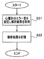
- the CPU 28 causes the sound analysis unit 102 to analyze the audio signal output from the microphone 101, and acquires analysis result information including sound feature data and volume data (S31).
- the CPU 28 stores the information of the analysis result in the flash memory 36 (S32).
- the high-frequency output device 12 obtains, that is, learns, an error sound of an electrocardiograph that is another medical device that cannot communicate, and stores sound information about the error sound in the flash memory 36 that is a storage device.
- the high-frequency output device 12 adjusts the output volume level generated by itself based on the electrocardiograph error sound stored in the learning mode.
- FIG. 11 is a flowchart illustrating an example of processing when an electrocardiograph error sound is generated in the high-frequency output device 12.
- the processing when the electrocardiograph error sound is generated in the high-frequency output device 12 will be described.
- the processing when the electrocardiograph error sound is generated in the ultrasonic output device 15 is the same, and the description thereof will be omitted. .
- the CPU 28 determines whether or not an electrocardiograph error sound has occurred based on the analysis result information from the sound analysis unit 102 (S41). This determination is performed by comparing the analysis result information from the sound analysis unit 102 input in real time with the electrocardiograph error sound information stored in the flash memory 36. When the input analysis result information from the sound analysis unit 102 matches the electrocardiograph error sound information stored in the flash memory 36, it is determined that an electrocardiograph error sound has occurred.
- each CPU that is a sound output control unit detects a predetermined sound output from an electrocardiograph as the third medical device, the output volume of the sound output from the speaker of its own medical device Is lower than the output volume of the sound output from the electrocardiograph.
- the high-frequency output device 12 and the ultrasonic output device 15 cooperate with each other in output volume level through communication, and other than the high-frequency output device 12 and the ultrasonic output device 15. Cooperation with the sound generated in the medical device can also be taken.
Abstract
A high-frequency wave output device (12) and an ultrasound output device (15), which are medical devices, have a CPU (28, 42), a communication circuit (31, 49), and a speaker (18, 19), respectively. When the output volume level of the sound outputted from the speaker of a related CPU has been modified, the related CPU transmits the modified output volume level information from the communication circuit to another medical device, and controls the output volume of the sound outputted from the related speaker on the basis of the output volume information of the sound outputted from the speaker of the other device received by the communication circuit.
Description
本発明は、医療システムに関し、特に、それぞれが音出力機能を有する複数の医療装置を含む医療システムに関する。
The present invention relates to a medical system, and more particularly to a medical system including a plurality of medical devices each having a sound output function. *
従来より、手術において、複数の医療装置が使用される場合がある。例えば、生体組織の切開及び凝固の行うための装置である超音波出力装置と高周波出力装置とが一緒に使用される場合がある。
Conventionally, a plurality of medical devices may be used in surgery. For example, an ultrasonic output device that is a device for performing incision and coagulation of biological tissue may be used together with a high-frequency output device.
超音波出力装置は、超音波振動により、処置対象の生体組織に対する処置を行う装置であり、高周波出力装置は、高周波電流により、その処置を行う装置である。これらの医療装置は、手術室に設置され、処置対象の部位、処置目的等に応じて使い分けられる。
The ultrasonic output device is a device that performs a treatment on a living tissue to be treated by ultrasonic vibration, and the high-frequency output device is a device that performs the treatment by high-frequency current. These medical devices are installed in the operating room, and are selectively used according to the region to be treated, the purpose of the treatment, and the like.
また、医療装置の中には、音を出力する機能を有するものもある。例えば、術者が処置のためのエネルギー出力の指示スイッチを押下してエネルギー出力を行うと、医療装置は、処置用のエネルギーを出力中であることを、術者に知らせるあるいは認識させるために、所定の音を所定の音量で出力する。このような音出力機能が装置毎に設けられ、その音量設定は装置毎に行われる。
Also, some medical devices have a function to output sound. For example, when the surgeon depresses an energy output instruction switch for treatment and outputs energy, the medical device informs or recognizes that the surgeon is outputting the treatment energy. A predetermined sound is output at a predetermined volume. Such a sound output function is provided for each apparatus, and the volume setting is performed for each apparatus.
従来の医療システムには、例えば、米国特許出願公開公報第2008/0015473号明細書に提案されているように、2つの医療装置が一緒に使用される場合に、2つの医療装置が互いに通信を行うシステムがある。
In conventional medical systems, for example when two medical devices are used together, as proposed in US Patent Application Publication No. 2008/0015473, the two medical devices communicate with each other. There is a system to do.
また、米国特許第6402741号明細書あるいは米国特許第5318563号明細書に提案されているように、医療機器がスピーカを有して、音により指示、あるいは音声メッセージを出力するものもある。
Also, as proposed in US Pat. No. 6,044,041 or US Pat. No. 5,318,563, there is a medical device having a speaker and outputting instructions or voice messages by sound.
しかし、従来の医療システムでは、スピーカからの音の出力音量の設定は医療装置毎に行われ、複数の医療装置間では出力音量レベルに関する連動あるいは連携はされていない。
However, in the conventional medical system, the output volume of the sound from the speaker is set for each medical device, and the multiple medical devices are not linked or linked with respect to the output volume level.
例えば、一の医療装置において出力音量レベルが変更されても、他の医療装置の出力音量レベルは変更されない。そのため、一の医療装置において変更された出力音量レベルが他の医療装置より出力される音の出力音量レベルより低いと、他の医療装置の音が出力されているときに、変更したその一の医療装置が出力する音を術者が認識できない虞がある。
For example, even if the output volume level is changed in one medical device, the output volume level of another medical device is not changed. Therefore, if the output volume level changed in one medical device is lower than the output volume level of the sound output from the other medical device, when the sound of the other medical device is output, the changed one There is a possibility that the surgeon cannot recognize the sound output from the medical device.
本願発明は、以上の問題に鑑みてなされたものであり、複数の医療装置間における出力音量レベルの連動あるいは連携が可能な医療システムを提供することを目的とする。
The present invention has been made in view of the above problems, and an object thereof is to provide a medical system capable of interlocking or linking output volume levels between a plurality of medical devices.
本発明の一態様の医療システムは、第1の医療装置と第2の医療装置とを含む医療システムであって、前記第1の医療装置と前記第2の医療装置のそれぞれに設けられ、所定の出力についての出力状態を検知する出力状態検知部と、前記第1の医療装置と前記第2の医療装置のそれぞれに設けられ、前記出力状態検知部により検知された前記出力状態に応じた音を出力する音出力部と、前記第1の医療装置と前記第2の医療装置のそれぞれに設けられ、前記出力状態検知部により検知された前記出力状態に応じて、前記音出力部から出力される前記音の出力を制御する音出力制御部と、前記第1の医療装置と前記第2の医療装置の一方に設けられ、前記音についての出力音量情報を、他方へ送信する第1の出力音量情報送信部と、前記第1の医療装置と前記第2の医療装置の前記他方に設けられ、前記第1の出力音量情報送信部から送信された前記出力音量情報を受信し、前記音出力制御部に伝達する第1の出力音量情報受信部と、を有し、前記他方の医療装置の音出力制御部は、前記第1の出力音量情報受信部において受信された前記第1の出力音量送信部からの前記出力音量情報に基づいて、前記音出力部から出力される前記音の前記出力音量を制御する。
A medical system according to one aspect of the present invention is a medical system including a first medical device and a second medical device, and is provided in each of the first medical device and the second medical device, and the predetermined medical system. An output state detection unit that detects an output state of each of the outputs, and a sound corresponding to the output state that is provided in each of the first medical device and the second medical device and is detected by the output state detection unit Is output from the sound output unit according to the output state detected by the output state detection unit, provided in each of the first medical device and the second medical device. A first output that is provided in one of the first medical device and the second medical device and that transmits output volume information about the sound to the other. A volume information transmitting unit; A first output volume that is provided on the other of the medical device and the second medical device, receives the output volume information transmitted from the first output volume information transmission unit, and transmits the output volume information to the sound output control unit And a sound output control unit of the other medical device based on the output volume information from the first output volume transmission unit received by the first output volume information reception unit. And controlling the output volume of the sound output from the sound output unit.
以下、本発明を、実施の形態により説明する。
Hereinafter, the present invention will be described with reference to embodiments.
(システム構成)
図1は、本発明の実施の形態に係る手術システムの構成を示す構成図である。手術システム1は、高周波治療装置2と、超音波治療装置3とを含んで構成される医療システムである。 (System configuration)
FIG. 1 is a configuration diagram showing a configuration of a surgical system according to an embodiment of the present invention. The surgical system 1 is a medical system that includes a high-frequency treatment device 2 and anultrasonic treatment device 3.
図1は、本発明の実施の形態に係る手術システムの構成を示す構成図である。手術システム1は、高周波治療装置2と、超音波治療装置3とを含んで構成される医療システムである。 (System configuration)
FIG. 1 is a configuration diagram showing a configuration of a surgical system according to an embodiment of the present invention. The surgical system 1 is a medical system that includes a high-frequency treatment device 2 and an
高周波治療装置2は、高周波電流によって処置対象の生体組織に対する処置を行う処置具としてのハンドピース11と、このハンドピース11に対して高周波電流を出力する高周波出力装置12とを有する医療装置である。超音波治療装置3は、超音波振動によって処置対象の生体組織に対する処置を行う処置具としてのハンドピース14と、このハンドピース14に内蔵された超音波振動子を超音波振動させるための超音波駆動信号を出力する超音波出力装置15とを有する医療装置である。
The high-frequency treatment device 2 is a medical device having a handpiece 11 as a treatment tool that performs a treatment on a living tissue to be treated with a high-frequency current, and a high-frequency output device 12 that outputs a high-frequency current to the handpiece 11. . The ultrasonic therapy apparatus 3 is an ultrasonic wave for ultrasonically vibrating a handpiece 14 as a treatment tool for performing a treatment on a living tissue to be treated by ultrasonic vibration, and an ultrasonic vibrator built in the handpiece 14. It is a medical device having an ultrasonic output device 15 that outputs a drive signal.
また、高周波出力装置12と超音波出力装置15は、通信ケーブル16により接続され、相互にデータ通信が可能となっている。
Further, the high-frequency output device 12 and the ultrasonic output device 15 are connected by a communication cable 16 so that mutual data communication is possible.
ハンドピース11は、把持部11aと、把持部11aから先端側に延出したシース部11bと、シース部11bの先端部に設けられた処置部(図示せず)とを有する処置具である。ケーブル11cが把持部11aの後端側から延出しており、ケーブル11cの後端のハンドピースコネクタ11dは、高周波出力装置12の出力コネクタに着脱自在となっている。
The handpiece 11 is a treatment instrument having a grip portion 11a, a sheath portion 11b extending from the grip portion 11a toward the distal end, and a treatment portion (not shown) provided at the distal end portion of the sheath portion 11b. The cable 11c extends from the rear end side of the grip portion 11a, and the handpiece connector 11d at the rear end of the cable 11c is detachable from the output connector of the high-frequency output device 12.
さらに、高周波出力装置12には、高周波出力指示のためのフットスイッチ17がケーブル17aを介して接続されている。術者は、フットスイッチ17を押下して操作することにより、ハンドピース11の処置部において、高周波電流による処置を行うことができる。
Furthermore, a foot switch 17 for instructing high frequency output is connected to the high frequency output device 12 via a cable 17a. The surgeon can perform a treatment with a high-frequency current in the treatment portion of the handpiece 11 by pressing and operating the foot switch 17.
ハンドピース14は、超音波出力指示のためのスイッチ(図示せず)が設けられた把持部14aと、把持部14aから先端側に延出するシース部14bと、シース部14bの先端部に設けられた処置部(図示せず)とを有する処置具である。ケーブル14cが、把持部14aの後端側から延出しており、ケーブル14cの後端のハンドピースコネクタ14dが超音波波出力装置15の出力コネクタに着脱自在となっている。術者は、ハンドピース14に設けられたスイッチ(図示せず)を押下して操作することにより、ハンドピース14の処置部において、超音波振動による処置を行うことができる。
The handpiece 14 is provided at a gripping portion 14a provided with a switch (not shown) for instructing ultrasonic output, a sheath portion 14b extending from the gripping portion 14a to the distal end side, and a distal end portion of the sheath portion 14b. A treatment tool (not shown). The cable 14c extends from the rear end side of the gripping portion 14a, and the handpiece connector 14d at the rear end of the cable 14c is detachable from the output connector of the ultrasonic wave output device 15. The surgeon can perform treatment by ultrasonic vibration in the treatment portion of the handpiece 14 by pressing and operating a switch (not shown) provided on the handpiece 14.
なお、後述するように、超音波出力装置15は、高周波出力装置12からの高周波電流信号である高周波出力の供給を受けて、高周波信号と超音波駆動信号の同時出力が可能となっている。よって、ケーブル14c内には高周波信号を伝達するための2本の高周波ケーブルも挿通されている。
Note that, as will be described later, the ultrasonic output device 15 receives a high-frequency output that is a high-frequency current signal from the high-frequency output device 12, and can simultaneously output a high-frequency signal and an ultrasonic drive signal. Therefore, two high-frequency cables for transmitting high-frequency signals are also inserted in the cable 14c.
さらに、高周波出力装置12と超音波出力装置15は、それぞれスピーカ18と19を有している。高周波出力装置12と超音波出力装置15は、それぞれ高周波出力と超音波出力がされているとき、等に、スピーカ18と19から所定の音を出力する。
Furthermore, the high-frequency output device 12 and the ultrasonic output device 15 have speakers 18 and 19, respectively. The high-frequency output device 12 and the ultrasonic output device 15 output a predetermined sound from the speakers 18 and 19 when the high-frequency output and the ultrasonic output are being output, respectively.
また、高周波出力装置12と超音波出力装置15には、それぞれ液晶表示装置(LCD)を有するタッチパネル20と21が設けられており、各種情報の表示、指示及び設定が可能となっている。
Further, the high frequency output device 12 and the ultrasonic output device 15 are provided with touch panels 20 and 21 having liquid crystal display devices (LCD), respectively, so that various information can be displayed, instructed and set.
(高周波出力装置の構成)
図2は、高周波出力装置12の構成を示すブロック図である。被検体に対する処置を行うための治療装置である高周波出力装置12は、正弦波及びバースト波を生成するための波形生成回路21を内蔵し、この波形生成回路21から出力される正弦波又はバースト波の信号は、共振回路22を経てアンプ23に入力される。 (Configuration of high-frequency output device)
FIG. 2 is a block diagram showing the configuration of the high-frequency output device 12. A high-frequency output device 12, which is a therapeutic device for performing treatment on a subject, includes a waveform generation circuit 21 for generating a sine wave and a burst wave, and a sine wave or burst wave output from the waveform generation circuit 21. The signal is input to the amplifier 23 via the resonance circuit 22.
図2は、高周波出力装置12の構成を示すブロック図である。被検体に対する処置を行うための治療装置である高周波出力装置12は、正弦波及びバースト波を生成するための波形生成回路21を内蔵し、この波形生成回路21から出力される正弦波又はバースト波の信号は、共振回路22を経てアンプ23に入力される。 (Configuration of high-frequency output device)
FIG. 2 is a block diagram showing the configuration of the high-
アンプ23により増幅された信号は、出力トランス24の1次巻線側に印加され、2次巻線側に焼灼用の高周波出力である高周波信号が発生する。
この出力トランス24の2次巻線は、出力される高周波信号を切り替えるリレー切替回路25を介して例えば4つの出力コネクタ26a、26b、26c、26dと、ドッキングコネクタ26eとに接続される。ドッキングコネクタ26eは、雌コネクタであり、後述する超音波出力装置15の雄型のドッキングコネクタ46cと接続される。ドッキングコネクタ26eは、高周波出力装置12の筐体の底板に設けられる。 The signal amplified by theamplifier 23 is applied to the primary winding side of the output transformer 24, and a high frequency signal which is a high frequency output for cauterization is generated on the secondary winding side.
The secondary winding of theoutput transformer 24 is connected to, for example, four output connectors 26a, 26b, 26c, and 26d and a docking connector 26e via a relay switching circuit 25 that switches an output high-frequency signal. The docking connector 26e is a female connector and is connected to a male docking connector 46c of the ultrasonic output device 15 described later. The docking connector 26 e is provided on the bottom plate of the housing of the high frequency output device 12.
この出力トランス24の2次巻線は、出力される高周波信号を切り替えるリレー切替回路25を介して例えば4つの出力コネクタ26a、26b、26c、26dと、ドッキングコネクタ26eとに接続される。ドッキングコネクタ26eは、雌コネクタであり、後述する超音波出力装置15の雄型のドッキングコネクタ46cと接続される。ドッキングコネクタ26eは、高周波出力装置12の筐体の底板に設けられる。 The signal amplified by the
The secondary winding of the
また、共振回路22には、電圧可変の電源回路27から電源電圧が供給され、波形生成回路21と電源回路27は、制御部である中央処理装置(以下、CPUという)28により制御される。CPU28は、出力モードの設定や出力設定値等に対応して、波形生成回路21と電源回路27を制御する。
上記出力トランス24の2次巻き線の出力信号は、検出部29を構成する電圧検出回路29aと電流検出回路29bとに入力される。
電圧検出回路29aと電流検出回路29bは、出力トランス24の2次巻き線から出力される高周波信号の電圧及び電流を検出すなわち測定する。検出された電圧と電流信号は、それぞれアナログデジタル変換器(以下、A/D変換器という)30a、30bによりデジタルの電圧信号及び電流信号に変換され、CPU28に入力される。 Further, theresonance circuit 22 is supplied with a power supply voltage from a voltage variable power supply circuit 27, and the waveform generation circuit 21 and the power supply circuit 27 are controlled by a central processing unit (hereinafter referred to as CPU) 28 as a control unit. The CPU 28 controls the waveform generation circuit 21 and the power supply circuit 27 in accordance with the output mode setting, the output set value, and the like.
The output signal of the secondary winding of theoutput transformer 24 is input to the voltage detection circuit 29a and the current detection circuit 29b that constitute the detection unit 29.
Thevoltage detection circuit 29a and the current detection circuit 29b detect or measure the voltage and current of the high-frequency signal output from the secondary winding of the output transformer 24. The detected voltage and current signals are converted into digital voltage signals and current signals by analog-digital converters (hereinafter referred to as A / D converters) 30a and 30b, respectively, and input to the CPU.
上記出力トランス24の2次巻き線の出力信号は、検出部29を構成する電圧検出回路29aと電流検出回路29bとに入力される。
電圧検出回路29aと電流検出回路29bは、出力トランス24の2次巻き線から出力される高周波信号の電圧及び電流を検出すなわち測定する。検出された電圧と電流信号は、それぞれアナログデジタル変換器(以下、A/D変換器という)30a、30bによりデジタルの電圧信号及び電流信号に変換され、CPU28に入力される。 Further, the
The output signal of the secondary winding of the
The
CPU28は、入力された電圧信号及び電流信号からそれらの積の高周波電力を検出すなわち算出する。そして、CPU28は、検出された高周波電力の値が予め設定された設定値となるように電源回路27の電源電圧を制御する。
また、CPU28は、通信を行う通信回路31を介して通信コネクタ32と接続されている。この通信コネクタ32は通信ケーブル16を介して、図3に示す超音波出力装置15側の通信コネクタ50と接続される。
上記リレー切替回路25と接続されたドッキングコネクタ26eは、上述したように超音波出力装置15側の雄コネクタであるドッキングコネクタ46cと着脱自在に接続される。 TheCPU 28 detects or calculates the high frequency power of the product from the input voltage signal and current signal. Then, the CPU 28 controls the power supply voltage of the power supply circuit 27 so that the value of the detected high frequency power becomes a preset setting value.
TheCPU 28 is connected to the communication connector 32 via a communication circuit 31 that performs communication. The communication connector 32 is connected to the communication connector 50 on the ultrasonic output device 15 side shown in FIG.
As described above, thedocking connector 26e connected to the relay switching circuit 25 is detachably connected to the docking connector 46c which is a male connector on the ultrasonic output device 15 side.
また、CPU28は、通信を行う通信回路31を介して通信コネクタ32と接続されている。この通信コネクタ32は通信ケーブル16を介して、図3に示す超音波出力装置15側の通信コネクタ50と接続される。
上記リレー切替回路25と接続されたドッキングコネクタ26eは、上述したように超音波出力装置15側の雄コネクタであるドッキングコネクタ46cと着脱自在に接続される。 The
The
As described above, the
また、このドッキングコネクタ26eにおける例えば2つ接続検知用コネクタピンは、ドッキングコネクタ接続検知回路33と接続され、このドッキングコネクタ接続検知回路33は、接続検知用コネクタピンを用いて、ドッキングコネクタ26eと超音波出力装置15のドッキングコネクタ46cとの接続を常時検知する。
For example, two connection detection connector pins in the docking connector 26e are connected to the docking connector connection detection circuit 33. The docking connector connection detection circuit 33 is connected to the docking connector 26e by using the connection detection connector pin. The connection with the docking connector 46c of the sound wave output device 15 is always detected.
この場合、2つの接続検知用コネクタピンは、他方のドッキングコネクタ46c側の例えば短絡設定された2つのコネクタピンと接続されるように設定されている
従って、2つの接続検知用コネクタピンが導通状態か否かを検知することにより、2つのドッキングコネクタ26eと46c同士が接続されているか否かの接続検知をすることができる。 In this case, the two connection detection connector pins are set so as to be connected to, for example, two short-circuited connector pins on theother docking connector 46c side.
Therefore, it is possible to detect whether or not the two docking connectors 26e and 46c are connected by detecting whether or not the two connection detection connector pins are in a conductive state.
従って、2つの接続検知用コネクタピンが導通状態か否かを検知することにより、2つのドッキングコネクタ26eと46c同士が接続されているか否かの接続検知をすることができる。 In this case, the two connection detection connector pins are set so as to be connected to, for example, two short-circuited connector pins on the
Therefore, it is possible to detect whether or not the two
そして、ドッキングコネクタ接続検知回路33による接続検知結果は、CPU28に伝達される。CPU28は、このドッキングコネクタ接続検知回路35による接続検知結果が未接続の場合には、超音波出力と高周波出力との同時出力を禁止する。
換言すると、CPU28は、ドッキングコネクタ26eと46cとが接続検知された場合のみ、超音波出力と高周波出力との同時出力を許可する。 Then, the connection detection result by the docking connectorconnection detection circuit 33 is transmitted to the CPU 28. When the connection detection result by the docking connector connection detection circuit 35 is not connected, the CPU 28 prohibits simultaneous output of ultrasonic output and high frequency output.
In other words, theCPU 28 permits simultaneous output of the ultrasonic output and the high frequency output only when the connection of the docking connectors 26e and 46c is detected.
換言すると、CPU28は、ドッキングコネクタ26eと46cとが接続検知された場合のみ、超音波出力と高周波出力との同時出力を許可する。 Then, the connection detection result by the docking connector
In other words, the
また、ドッキングコネクタ接続検知回路33は、2つのドッキングコネクタ26eと46c同士の接続を検知し、かつ超音波出力と高周波出力の同時出力が指示あるいは設定されている場合には、出力トランス24の出力信号がドッキングコネクタ26e側に出力されるように、リレー切替回路25を切り替える。なお、ドッキングコネクタ接続検知回路33でなく、CPU28がその切替の制御を行うようにしても良い。
さらに、CPU28には、フットスイッチ17からの操作信号が、ケーブル17aが接続されるコネクタ34を介して入力される。 The docking connectorconnection detection circuit 33 detects the connection between the two docking connectors 26e and 46c, and outputs or outputs from the output transformer 24 when simultaneous output of ultrasonic output and high frequency output is instructed or set. The relay switching circuit 25 is switched so that a signal is output to the docking connector 26e side. The CPU 28 may control the switching instead of the docking connector connection detection circuit 33.
Furthermore, an operation signal from thefoot switch 17 is input to the CPU 28 via a connector 34 to which the cable 17a is connected.
さらに、CPU28には、フットスイッチ17からの操作信号が、ケーブル17aが接続されるコネクタ34を介して入力される。 The docking connector
Furthermore, an operation signal from the
さらにまた、高周波出力装置12のスピーカ18は、CPU28の制御の下、音源回路35により駆動される。フットスイッチ17が操作されて高周波出力の指示がされると、CPU28は、その指示がされている間、高周波出力に応じた音を所定の出力音量レベルで出力するように、音源回路35を制御する。また、高周波出力装置12においてエラーが発生すると、CPU28は、そのエラー出力中、エラーの発生を示す音を所定の出力音量レベルで出力するように、音源回路35を制御する。
Furthermore, the speaker 18 of the high-frequency output device 12 is driven by the sound source circuit 35 under the control of the CPU 28. When the foot switch 17 is operated to instruct high frequency output, the CPU 28 controls the sound source circuit 35 so as to output a sound corresponding to the high frequency output at a predetermined output volume level while the instruction is given. To do. When an error occurs in the high-frequency output device 12, the CPU 28 controls the sound source circuit 35 so that a sound indicating the occurrence of the error is output at a predetermined output volume level during the error output.
すなわち、CPU28は、エネルギー出力、エラー出力等の所定の出力についての出力状態を検知する出力状態検知部を構成し、所定の出力が検知されると、その出力に応じた音を所定の出力音量レベルで出力する。CPU28は、所定の出力を検知すると、その検知された出力状態に応じて、スピーカ18から出力される音の出力を制御する音出力制御部を構成する。そして、スピーカ18は、その検知された出力状態に応じた音を出力する音出力部を構成する。
That is, the CPU 28 constitutes an output state detection unit that detects an output state of a predetermined output such as an energy output and an error output. When the predetermined output is detected, a sound corresponding to the output is output to a predetermined output volume. Output by level. When the CPU 28 detects a predetermined output, the CPU 28 configures a sound output control unit that controls the output of the sound output from the speaker 18 according to the detected output state. And the speaker 18 comprises the sound output part which outputs the sound according to the detected output state.
高周波出力装置12のタッチパネル20は、操作信号、設定信号などの入力信号をCPU28へ出力し、CPU28からの画像信号に基づいて、画像をLCDの画面上に表示する。ユーザは、タッチパネル20の画面を用いて、スピーカ18から出力される音の音量を設定することができる。
The touch panel 20 of the high-frequency output device 12 outputs an input signal such as an operation signal or a setting signal to the CPU 28 and displays an image on the LCD screen based on the image signal from the CPU 28. The user can set the volume of the sound output from the speaker 18 using the screen of the touch panel 20.
高周波出力装置12は、CPU28に接続されたフラッシュメモリ36を有する。フラッシュメモリ36には、高周波出力制御プログラム、出力音量設定プログラム、各種設定値などが記憶されている。
The high frequency output device 12 has a flash memory 36 connected to the CPU 28. The flash memory 36 stores a high frequency output control program, an output volume setting program, various setting values, and the like.
従って、ハンドピース11が高周波出力装置12に接続され、フットスイッチ17が押下されると、CPU28は、出力トランス24から指定あるいは設定された値の高周波出力を、ハンドピース11が接続された出力コネクタから出力するように、波形生成回路21及び電源回路27を制御する。CPU28は、高周波出力が指示されているとき、すなわちフットスイッチ17が押下されてエネルギー出力が指示されている間、所定の音をスピーカ18から出力し続ける。
Therefore, when the handpiece 11 is connected to the high-frequency output device 12 and the foot switch 17 is pressed, the CPU 28 outputs a high-frequency output of a value designated or set from the output transformer 24 to the output connector to which the handpiece 11 is connected. The waveform generation circuit 21 and the power supply circuit 27 are controlled so as to be output from. The CPU 28 continues to output a predetermined sound from the speaker 18 when the high frequency output is instructed, that is, while the foot switch 17 is pressed and the energy output is instructed.
また、CPU28は、高周波出力装置12において発生したエラーがあれば、そのエラーを検出して、音源回路35を駆動して所定のエラー出力に対応する音をスピーカ18から出力する。
Further, if there is an error that has occurred in the high-frequency output device 12, the CPU 28 detects the error and drives the sound source circuit 35 to output a sound corresponding to a predetermined error output from the speaker 18.
なお、CPU28は、エラーの発生状態を示す情報を、フラッシュメモリ36の所定の記憶領域に書き込む。例えば、高周波出力装置12内において何らかのエラーが発生すると、そのエラー出力がCPU28によって検出され、CPU28は、所定の記憶領域に、エラーが発生していることを示す1のフラグにセットする。エラーの発生原因がなくなると、エラー出力も出力されなくなるので、CPU28は、その所定領域に書き込んでセットしたフラグを、エラーが発生していないことを示す0に書き換える。そして、CPU28は、エラーの有無を示すフラグの状態に変化があると、通信回路31を介して、超音波出力装置15へフラグ情報を送信する処理を行う。
Note that the CPU 28 writes information indicating an error occurrence state in a predetermined storage area of the flash memory 36. For example, when an error occurs in the high-frequency output device 12, the error output is detected by the CPU 28, and the CPU 28 sets a flag 1 indicating that an error has occurred in a predetermined storage area. When the cause of occurrence of the error disappears, no error output is output, so the CPU 28 rewrites the flag written and set in the predetermined area to 0 indicating that no error has occurred. Then, when there is a change in the state of the flag indicating the presence or absence of an error, the CPU 28 performs a process of transmitting flag information to the ultrasonic output device 15 via the communication circuit 31.
(超音波出力装置の構成)
図3は、超音波出力装置15の構成を示すブロック部である。被検体に対する処置を行うための治療装置である超音波出力装置15は、発振回路を内蔵した出力制御回路41を有する。この出力制御回路41は、制御部としてのCPU42の制御下で、その発振回路で発振された発振信号の周波数と電流を調整してアンプ43に出力する。
アンプ43により増幅された信号は、出力回路44に入力され、この出力回路44の図示しないトランスにより電圧増幅されて、トランスの2次巻き線から超音波駆動(出力)信号として出力される。 (Configuration of ultrasonic output device)
FIG. 3 is a block diagram showing the configuration of theultrasonic output device 15. An ultrasonic output device 15 which is a treatment device for performing treatment on a subject has an output control circuit 41 having a built-in oscillation circuit. The output control circuit 41 adjusts the frequency and current of the oscillation signal oscillated by the oscillation circuit and outputs the result to the amplifier 43 under the control of the CPU 42 as a control unit.
The signal amplified by theamplifier 43 is input to the output circuit 44, voltage amplified by a transformer (not shown) of the output circuit 44, and output as an ultrasonic drive (output) signal from the secondary winding of the transformer.
図3は、超音波出力装置15の構成を示すブロック部である。被検体に対する処置を行うための治療装置である超音波出力装置15は、発振回路を内蔵した出力制御回路41を有する。この出力制御回路41は、制御部としてのCPU42の制御下で、その発振回路で発振された発振信号の周波数と電流を調整してアンプ43に出力する。
アンプ43により増幅された信号は、出力回路44に入力され、この出力回路44の図示しないトランスにより電圧増幅されて、トランスの2次巻き線から超音波駆動(出力)信号として出力される。 (Configuration of ultrasonic output device)
FIG. 3 is a block diagram showing the configuration of the
The signal amplified by the
この超音波駆動信号は、この信号を切り替えて出力するリレー切替回路45を介して2つの出力コネクタ46a、46bに出力される。なお、アンプ43のゲインは、CPU42により制御される。
2つの出力コネクタのうちの1つの出力コネクタ46aは、雄コネクタであるドッキングコネクタ46cとも接続されている。ドッキングコネクタ46cは、超音波出力装置15の筐体の天板に設けられる。出力コネクタ46aには、モノポーラの高周波電流出力も可能なハンドピースが接続可能となっている。なお、ここでは、超音波出力装置15とハンドピース14がモノポーラの高周波電流を出力する場合を説明するが、超音波出力装置15とハンドピース14は、バイポーラの高周波電流を出力するものであってもよい。 The ultrasonic drive signal is output to the two output connectors 46a and 46b via a relay switching circuit 45 that switches and outputs this signal. Note that the gain of the amplifier 43 is controlled by the CPU 42.
Oneoutput connector 46a of the two output connectors is also connected to a docking connector 46c which is a male connector. The docking connector 46 c is provided on the top plate of the casing of the ultrasonic output device 15. A handpiece capable of monopolar high-frequency current output can be connected to the output connector 46a. Here, the case where the ultrasonic output device 15 and the handpiece 14 output a monopolar high-frequency current will be described. However, the ultrasonic output device 15 and the handpiece 14 output a bipolar high-frequency current. Also good.
2つの出力コネクタのうちの1つの出力コネクタ46aは、雄コネクタであるドッキングコネクタ46cとも接続されている。ドッキングコネクタ46cは、超音波出力装置15の筐体の天板に設けられる。出力コネクタ46aには、モノポーラの高周波電流出力も可能なハンドピースが接続可能となっている。なお、ここでは、超音波出力装置15とハンドピース14がモノポーラの高周波電流を出力する場合を説明するが、超音波出力装置15とハンドピース14は、バイポーラの高周波電流を出力するものであってもよい。 The ultrasonic drive signal is output to the two
One
なお、出力コネクタ46bには、ドッキングコネクタ46cとは接続されていないで、高周波出力装置12とは独立して超音波を出力する超音波専用のハンドピースが接続される。
The output connector 46b is not connected to the docking connector 46c, but is connected to an ultrasonic handpiece that outputs ultrasonic waves independently of the high-frequency output device 12.
出力回路44から出力される超音波駆動信号は、検出部47を構成する電圧検出回路47aと電流検出回路47bとに入力され、それぞれ電圧及び電流が検出すなわち測定される。検出された電圧及び電流は、電圧検出回路47aと電流検出回路47b内部のA/D変換器を介してそれぞれCPU42に入力される。
CPU42は、設定された電力を出力回路44から出力するように、検出部47で検出された電圧及び電流に基づいて出力制御回路41を介して定電流制御を行う。 The ultrasonic drive signal output from theoutput circuit 44 is input to the voltage detection circuit 47a and the current detection circuit 47b constituting the detection unit 47, and the voltage and current are detected, that is, measured. The detected voltage and current are input to the CPU 42 via the A / D converters in the voltage detection circuit 47a and the current detection circuit 47b, respectively.
TheCPU 42 performs constant current control via the output control circuit 41 based on the voltage and current detected by the detection unit 47 so as to output the set power from the output circuit 44.
CPU42は、設定された電力を出力回路44から出力するように、検出部47で検出された電圧及び電流に基づいて出力制御回路41を介して定電流制御を行う。 The ultrasonic drive signal output from the
The
このため、出力回路44から出力する際の出力値の制御情報を、出力制御回路41内のメモリに一時保持し、CPU42はその後に検出された電圧及び電流により出力制御回路41を介して直前の制御情報を補正するように制御する。
また、CPU42は、通信を行う通信回路49を介して通信コネクタ50と接続されている。この通信コネクタ50は通信ケーブル16を介して図2に示す高周波出力装置12側の通信コネクタ32と接続される。よって、CPU42とCPU28は、通信ケーブル16を介して互いに送受信を行うことができる。
また、2つの出力コネクタ46a、46bにおけるコネクタ接続検知ピンは、ハンドピースコネクタ接続検知回路(以下、HPコネクタ接続検知回路という)51と接続されている。そして、このHPコネクタ接続検知回路51は、ハンドピースコネクタ14dの出力コネクタ46a、46bへの接続/未接続を検知し、その検知結果をCPU42へ出力する。 Therefore, the control information of the output value at the time of output from theoutput circuit 44 is temporarily held in the memory in the output control circuit 41, and the CPU 42 immediately follows the output control circuit 41 through the output control circuit 41 by the detected voltage and current. Control is performed to correct the control information.
TheCPU 42 is connected to the communication connector 50 via a communication circuit 49 that performs communication. The communication connector 50 is connected to the communication connector 32 on the high-frequency output device 12 side shown in FIG. Therefore, the CPU 42 and the CPU 28 can transmit and receive each other via the communication cable 16.
The connector connection detection pins in the two output connectors 46a and 46b are connected to a handpiece connector connection detection circuit (hereinafter referred to as an HP connector connection detection circuit) 51. The HP connector connection detection circuit 51 detects connection / non-connection of the handpiece connector 14d to the output connectors 46a, 46b, and outputs the detection result to the CPU 42.
また、CPU42は、通信を行う通信回路49を介して通信コネクタ50と接続されている。この通信コネクタ50は通信ケーブル16を介して図2に示す高周波出力装置12側の通信コネクタ32と接続される。よって、CPU42とCPU28は、通信ケーブル16を介して互いに送受信を行うことができる。
また、2つの出力コネクタ46a、46bにおけるコネクタ接続検知ピンは、ハンドピースコネクタ接続検知回路(以下、HPコネクタ接続検知回路という)51と接続されている。そして、このHPコネクタ接続検知回路51は、ハンドピースコネクタ14dの出力コネクタ46a、46bへの接続/未接続を検知し、その検知結果をCPU42へ出力する。 Therefore, the control information of the output value at the time of output from the
The
The connector connection detection pins in the two
CPU42は、検知結果の情報に基づいて、ハンドピースが接続された出力コネクタに出力回路44からの出力信号(つまり、超音波駆動信号)を供給するように、出力制御回路41を介してリレー切替回路45の切替を制御する。なお、CPU42がリレー切替回路45の切替を直接制御するようにしても良い。
さらに、超音波出力装置15は、音源回路52により駆動されるスピーカ19を有している。ハンドピース14のスイッチが操作されて超音波出力の指示がされると、CPU42は、その指示がされている間、超音波出力に応じた音を所定の出力音量レベルで出力するように、音源回路52を制御する。また、超音波出力装置15においてエラーが発生すると、CPU42は、そのエラー出力中、エラーの発生を示す音を所定の出力音量レベルで出力するように、音源回路52を制御する。 TheCPU 42 switches the relay via the output control circuit 41 so as to supply the output signal (that is, the ultrasonic drive signal) from the output circuit 44 to the output connector to which the handpiece is connected based on the detection result information. The switching of the circuit 45 is controlled. Note that the CPU 42 may directly control switching of the relay switching circuit 45.
Further, theultrasonic output device 15 has a speaker 19 driven by a sound source circuit 52. When the switch of the handpiece 14 is operated and an instruction for ultrasonic output is given, the CPU 42 outputs a sound corresponding to the ultrasonic output at a predetermined output volume level while the instruction is given. The circuit 52 is controlled. When an error occurs in the ultrasonic output device 15, the CPU 42 controls the sound source circuit 52 so that a sound indicating the occurrence of the error is output at a predetermined output volume level during the error output.
さらに、超音波出力装置15は、音源回路52により駆動されるスピーカ19を有している。ハンドピース14のスイッチが操作されて超音波出力の指示がされると、CPU42は、その指示がされている間、超音波出力に応じた音を所定の出力音量レベルで出力するように、音源回路52を制御する。また、超音波出力装置15においてエラーが発生すると、CPU42は、そのエラー出力中、エラーの発生を示す音を所定の出力音量レベルで出力するように、音源回路52を制御する。 The
Further, the
すなわち、CPU42は、エネルギー出力、エラー出力等の所定の出力についての出力状態を検知する出力状態検知部を構成し、所定の出力が検知されると、その出力に応じた音を所定の出力音量レベルで出力する。CPU42は、所定の出力を検知すると、その検知された出力状態に応じて、スピーカ19から出力される音の出力を制御する音出力制御部を構成する。そして、スピーカ19は、その検知された出力状態に応じた音を出力する音出力部を構成する。
That is, the CPU 42 constitutes an output state detection unit that detects an output state for a predetermined output such as an energy output and an error output. When the predetermined output is detected, a sound corresponding to the output is output to a predetermined output volume. Output by level. When detecting a predetermined output, the CPU 42 constitutes a sound output control unit that controls the output of the sound output from the speaker 19 in accordance with the detected output state. And the speaker 19 comprises the sound output part which outputs the sound according to the detected output state.
超音波出力装置15のタッチパネル21は、操作信号、設定信号などの入力信号をCPU42へ出力し、CPU42からの画像信号に基づいて、画像をLCDの画面上に表示する。ユーザは、タッチパネル21の画面を用いて、スピーカ19から出力される音の音量を設定することができる。
The touch panel 21 of the ultrasonic output device 15 outputs input signals such as operation signals and setting signals to the CPU 42 and displays an image on the LCD screen based on the image signal from the CPU 42. The user can set the volume of the sound output from the speaker 19 using the screen of the touch panel 21.
超音波出力装置15は、CPU42に接続されたフラッシュメモリ53を有する。フラッシュメモリ53には、超音波出力制御プログラム、出力音量設定プログラム、各種設定値などが記憶されている。
The ultrasonic output device 15 has a flash memory 53 connected to the CPU 42. The flash memory 53 stores an ultrasonic output control program, an output volume setting program, various setting values, and the like.
従って、ハンドピース14が超音波出力装置15に接続され、図示しない超音波出力指示のためのスイッチが押下されると、ハンドピース14の接続された出力コネクタとHPコネクタ接続検知回路51とを介して超音波出力指示信号がCPU42に入力される。CPU42は、出力回路44から指定あるいは設定された値の超音波出力を、ハンドピース14が接続された出力コネクタから出力するように、出力制御回路41を制御する。
Accordingly, when the handpiece 14 is connected to the ultrasonic output device 15 and a switch for instructing ultrasonic output (not shown) is pressed, the output connector to which the handpiece 14 is connected and the HP connector connection detection circuit 51 are connected. Then, an ultrasonic output instruction signal is input to the CPU 42. The CPU 42 controls the output control circuit 41 so that an ultrasonic output having a value designated or set from the output circuit 44 is output from the output connector to which the handpiece 14 is connected.
また、高周波出力と超音波出力の同時出力が指定あるいは設定されているときは、図示しない超音波出力指示のためのスイッチが押下されると、CPU42は、超音波出力のために出力制御回路41を制御すると共に、通信回路49及び通信ケーブル16を介して、高周波出力装置12のCPU28へ、高周波出力を指示する。高周波出力装置12は、通信ケーブル16と通信回路31を介して超音波出力装置15からの高周波出力指示を受信すると、電源回路27、波形生成回路21及びドッキングコネクタ接続検知回路33を制御して、リレー切替回路25の高周波出力を、ドッキングコネクタ26e、46cを介して超音波出力装置15へ供給する。その結果、出力コネクタ46aから超音波出力と高周波出力が同時に出力される。
When simultaneous output of high frequency output and ultrasonic output is designated or set, when a switch for instructing ultrasonic output (not shown) is pressed, the CPU 42 outputs control circuit 41 for ultrasonic output. And the CPU 28 of the high-frequency output device 12 is instructed to output a high frequency via the communication circuit 49 and the communication cable 16. When receiving the high frequency output instruction from the ultrasonic output device 15 via the communication cable 16 and the communication circuit 31, the high frequency output device 12 controls the power supply circuit 27, the waveform generation circuit 21, and the docking connector connection detection circuit 33, The high frequency output of the relay switching circuit 25 is supplied to the ultrasonic output device 15 via the docking connectors 26e and 46c. As a result, an ultrasonic output and a high frequency output are simultaneously output from the output connector 46a.
CPU42は、超音波出力が指示されているとき、すなわちハンドピース14のスイッチが押下されてエネルギー出力が指示されている間、所定の音をスピーカ19から出力し続ける。
The CPU 42 continues to output a predetermined sound from the speaker 19 when the ultrasonic output is instructed, that is, while the switch of the handpiece 14 is pressed and the energy output is instructed.
また、CPU42は、超音波出力装置15において発生したエラーがあれば、そのエラーを検出して、所定のエラー音を音源回路52を駆動してスピーカ19から出力する。同時に、CPU42は、エラーの発生状態を示す情報を、フラッシュメモリ53の所定の記憶領域に書き込む。例えば、超音波出力装置15内において何らかのエラーが発生すると、そのエラー出力がCPU42によって検出され、CPU42は、所定の記憶領域に、エラーが発生していることを示す1のフラグにセットする。エラーの発生原因がなくなると、エラー出力も出力されなくなるので、CPU42は、その所定の領域に書き込んでセットしたフラグを、エラーが発生していないことを示す0に書き換える。そして、CPU42は、エラーの有無を示すフラグの状態に変化があると、通信回路49を介して、高周波出力装置12へフラグ情報を送信する処理を行う。
Further, if there is an error generated in the ultrasonic output device 15, the CPU 42 detects the error and drives the sound source circuit 52 to output a predetermined error sound from the speaker 19. At the same time, the CPU 42 writes information indicating an error occurrence state in a predetermined storage area of the flash memory 53. For example, when an error occurs in the ultrasonic output device 15, the error output is detected by the CPU 42, and the CPU 42 sets a flag 1 indicating that an error has occurred in a predetermined storage area. When the cause of occurrence of the error disappears, no error output is output, so the CPU 42 rewrites the flag written and set in the predetermined area to 0 indicating that no error has occurred. Then, when there is a change in the state of the flag indicating the presence or absence of an error, the CPU 42 performs processing for transmitting flag information to the high frequency output device 12 via the communication circuit 49.
なお、出力音量レベルについて、高周波出力装置12と超音波出力装置15のいずれがマスタ装置であるかが、予め設定され、そのマスタ装置として設定あるいは指定された装置は、フラッシュメモリにそのマスタ装置であることを示す情報が記録される。マスタ装置の設定は、例えば、タッチパネルにその設定画面を表示し、ユーザに選択させることによって行われる。ここでは、超音波出力装置15がマスタ装置として設定されているとして、以下、説明する。
Regarding the output volume level, which one of the high-frequency output device 12 and the ultrasonic output device 15 is the master device is preset, and the device set or designated as the master device is stored in the flash memory as the master device. Information indicating that it exists is recorded. The setting of the master device is performed by, for example, displaying the setting screen on the touch panel and allowing the user to select it. Here, the ultrasonic output device 15 will be described below as the master device.
(出力音量レベルの設定)
次に、高周波出力装置12と超音波出力装置15における、音量設定について説明する。高周波出力装置12と超音波出力装置15のそれぞれにおいて、スピーカ18,19から出力される音の音量レベル、すなわち出力音量レベル、の設定を行うことができる。 (Output volume level setting)
Next, volume setting in the high-frequency output device 12 and the ultrasonic output device 15 will be described. In each of the high-frequency output device 12 and the ultrasonic output device 15, the volume level of the sound output from the speakers 18 and 19, that is, the output volume level can be set.
次に、高周波出力装置12と超音波出力装置15における、音量設定について説明する。高周波出力装置12と超音波出力装置15のそれぞれにおいて、スピーカ18,19から出力される音の音量レベル、すなわち出力音量レベル、の設定を行うことができる。 (Output volume level setting)
Next, volume setting in the high-
図4は、タッチパネル20と21に表示される出力音量設定画面の例を示す図である。例えば、術者等のユーザが高周波出力装置12のタッチパネル20の画面上に表示される所定のメニュー画面から所定の操作あるいはコマンド入力を行うと、図4の出力音量設定変更画面SSが、タッチパネル20の画面上に表示される。出力音量設定変更画面SSは、タッチパネル20の画面全体に表示されてもよいし、その画面の一部として表示されてもよいし、さらにあるいは、画面上にポップアップウインドウとして表示されてもよい。
FIG. 4 is a diagram showing an example of an output volume setting screen displayed on the touch panels 20 and 21. For example, when a user such as an operator performs a predetermined operation or command input from a predetermined menu screen displayed on the screen of the touch panel 20 of the high frequency output device 12, the output volume setting change screen SS of FIG. Displayed on the screen. The output volume setting change screen SS may be displayed on the entire screen of the touch panel 20, may be displayed as a part of the screen, or may be displayed as a pop-up window on the screen.
出力音量設定変更画面SSは、出力音量の設定変更のための画面であることを示す文字61とスピーカのアイコン62の表示と共に、出力音量レベルが複数レベルの内のどのレベルにあるかを示すレベル表示部63と、レベル変更のための操作ボタン表示部64とを含む。操作ボタン表示部64は、+(プラス)ボタン64aと、-(マイナス)ボタン64bとを含む。
The output volume setting change screen SS is a level indicating which output volume level is at a level among a plurality of levels, along with display of characters 61 and a speaker icon 62 indicating that the screen is for changing the output volume setting. A display unit 63 and an operation button display unit 64 for changing the level are included. The operation button display unit 64 includes a + (plus) button 64a and a-(minus) button 64b.
レベル表示部63は、現在設定されている出力音量レベルを、複数段階(ここでは10段階)のうちのどのレベルにあるかを、バーのレベルで表示する。図4では、出力音量レベルがレベル6に設定されていることが、1~6個の白いブロックが縦に並んだ左側の6つのバーと、7~10個の斜線ブロックが縦に並んだ右側の4つのバーとの表示により、示されている。
The level display unit 63 displays the currently set output volume level as a bar level indicating which level of a plurality of levels (here, 10 levels) is present. In FIG. 4, the output volume level is set to level 6; the left six bars with 1-6 white blocks arranged vertically and the right side with 7-10 diagonal blocks arranged vertically This is indicated by the display with four bars.
例えば、ユーザが操作ボタン表示部64の+(プラス)ボタン64aを1回タッチすると、出力音量レベルが1レベルだけ上がる。図4の表示状態で、出力音量レベルが1レベルだけ上がると、レベル表示部63は、1~7個の白いブロックが縦に並んだ左側の7つのバーと、8~10個の斜線ブロックが縦に並んだ右側の3つのバーの表示になり、出力音量レベルがレベル7に設定されていることを表示する状態に、レベル表示部63の表示内容は変更される。
For example, when the user touches the + (plus) button 64a of the operation button display unit 64 once, the output volume level increases by one level. In the display state of FIG. 4, when the output volume level is increased by one level, the level display unit 63 has seven bars on the left side in which 1 to 7 white blocks are vertically arranged and 8 to 10 diagonal blocks. The display content of the level display section 63 is changed to a state in which three bars on the right side are displayed vertically and the output volume level is set to level 7.
同様に、ユーザが操作ボタン表示部64の-(マイナス)ボタン64bを1回タッチすると、出力音量レベルが1レベルだけ下がる。図4の表示状態で、出力音量レベルが1レベルだけ下がると、レベル表示部63は、1~5個の白いブロックが縦に並んだ左側の5つのバーと、6~10個の斜線ブロックが縦に並んだ右側の5つのバーの表示になり、出力音量レベルがレベル5に設定されていることを表示する状態に、レベル表示部63の表示内容は変更される。
Similarly, when the user touches the-(minus) button 64b of the operation button display unit 64 once, the output volume level decreases by one level. In the display state of FIG. 4, when the output volume level is lowered by one level, the level display unit 63 has five bars on the left side in which 1 to 5 white blocks are arranged vertically and 6 to 10 diagonal blocks. The display content of the level display unit 63 is changed to a state in which five bars on the right side are displayed vertically and the output volume level is set to level 5.
出力音量レベルが設定変更されると、CPU28は、その変更された出力音量レベルのデータを、フラッシュメモリ36に書き込んで記憶すると共に、通信回路31を介して超音波出力装置15へ、その変更された出力音量レベルのデータを送信する。そして、高周波出力装置12でスピーカ18から出力される音の出力音量レベルの設定が行われると、超音波出力装置15においてもそのスピーカ19から出力される音の同じ出力音量レベルも、高周波出力装置12で設定変更された出力音量レベルと同じレベルに変更される。
When the output volume level is changed, the CPU 28 writes and stores the changed output volume level data in the flash memory 36 and changes the data to the ultrasonic output device 15 via the communication circuit 31. Transmits output volume level data. When the output volume level of the sound output from the speaker 18 is set by the high frequency output device 12, the same output volume level of the sound output from the speaker 19 is also set in the ultrasonic output device 15. 12 is changed to the same level as the output volume level changed in setting.
ユーザは、超音波出力装置15のタッチパネル21においても、同様にスピーカ19から出力される音の出力音量レベルの設定変更を行うことができる。超音波出力装置15において、音の出力音量レベルの変更がされると、CPU42によって、その変更された出力音量レベルのデータが、フラッシュメモリ53に書き込まれて記憶されると共に、通信回路49を介して高周波出力装置12へ、その変更された出力音量レベルのデータを送信する。そして、超音波出力装置15でスピーカ19から出力される音の出力音量レベルの設定が行われると、高周波出力装置12においてもそのスピーカ18から出力される音の同じ出力音量レベルも、超音波出力装置15で設定変更された出力音量レベルと同じレベルに変更される。
The user can similarly change the setting of the output volume level of the sound output from the speaker 19 on the touch panel 21 of the ultrasonic output device 15. When the sound output volume level is changed in the ultrasonic output device 15, the data of the changed output volume level is written and stored in the flash memory 53 by the CPU 42 and also via the communication circuit 49. Then, the data of the changed output volume level is transmitted to the high-frequency output device 12. When the output volume level of the sound output from the speaker 19 is set by the ultrasonic output device 15, the same output volume level of the sound output from the speaker 18 is also output by the ultrasonic output in the high frequency output device 12. The output level is changed to the same level as the output volume level changed by the device 15.
よって、高周波出力装置12と超音波出力装置15のいずれか一方でスピーカから出力される音の出力音量レベルの設定変更を行うと、他方においてもスピーカから出力される音の同じ出力音量レベルも、一方で設定変更された出力音量レベルと同一の出力音量レベルに変更される。
Therefore, when the setting change of the output volume level of the sound output from the speaker is performed in either the high-frequency output device 12 or the ultrasonic output device 15, the same output volume level of the sound output from the speaker is also detected on the other side. On the other hand, the output volume level is changed to the same output volume level as the changed setting.
ここでは、高周波出力装置12と超音波出力装置15が同じ出力音量レベルに設定されると、2つのスピーカ18と19から出力される音の出力音量が同じである。しかし、高周波出力装置12と超音波出力装置15に設定される出力音量レベルの値と、実際に出力される音の出力音量が一致していない場合がある。例えば、高周波出力装置12がレベル5の時に実際に出力される音の出力音量が、超音波出力装置15がレベル7の時に実際に出力される音の出力音量と等しい場合がある。
Here, when the high-frequency output device 12 and the ultrasonic output device 15 are set to the same output volume level, the output volumes of the sounds output from the two speakers 18 and 19 are the same. However, the output volume level value set in the high-frequency output device 12 and the ultrasonic output device 15 may not match the output volume of the actually output sound. For example, the output volume of the sound that is actually output when the high-frequency output device 12 is level 5 may be equal to the output volume of the sound that is actually output when the ultrasonic output device 15 is level 7.
このような場合は、高周波出力装置12と超音波出力装置15は、それぞれ自己と相手の出力音量レベルの対応情報を有して、相手から設定変更された出力音量レベルの情報を受信すると、自己と相手において実際に出力される音の出力音量が等しくなるように、その対応情報に基づいて、自己の出力音量レベルを変更するようにすればよい。
In such a case, each of the high-frequency output device 12 and the ultrasonic output device 15 has the corresponding information of the output volume level of itself and the other party, and receives the information of the output volume level changed from the other party. And the other party may change their output volume level based on the correspondence information so that the output volume of the sound actually output by the other party becomes equal.
(出力音量レベルの連携処理)
次に、出力音量レベルの連携処理について説明する。ここでも、超音波出力装置15が、出力音量レベルについてのマスタ装置として予め設定されている場合で説明する。
(起動時)
図5は、高周波出力装置12と超音波出力装置15の起動時の出力音量レベルの設定処理の流れの例を示すフローチャートである。高周波出力装置12と超音波出力装置15のそれぞれは、電源スイッチがONされて起動すると、CPU28と42は、それぞれフラッシュメモリ36とフラッシュメモリ53から起動時音量設定プログラムを読み出して実行する。 (Output volume level linkage processing)
Next, output volume level linkage processing will be described. Here, the case where theultrasonic output device 15 is preset as a master device for the output volume level will be described.
(At startup)
FIG. 5 is a flowchart showing an example of the flow of the output volume level setting process when the high-frequency output device 12 and the ultrasonic output device 15 are activated. When each of the high-frequency output device 12 and the ultrasonic output device 15 is activated with the power switch turned on, the CPUs 28 and 42 read and execute a startup volume setting program from the flash memory 36 and the flash memory 53, respectively.
次に、出力音量レベルの連携処理について説明する。ここでも、超音波出力装置15が、出力音量レベルについてのマスタ装置として予め設定されている場合で説明する。
(起動時)
図5は、高周波出力装置12と超音波出力装置15の起動時の出力音量レベルの設定処理の流れの例を示すフローチャートである。高周波出力装置12と超音波出力装置15のそれぞれは、電源スイッチがONされて起動すると、CPU28と42は、それぞれフラッシュメモリ36とフラッシュメモリ53から起動時音量設定プログラムを読み出して実行する。 (Output volume level linkage processing)
Next, output volume level linkage processing will be described. Here, the case where the
(At startup)
FIG. 5 is a flowchart showing an example of the flow of the output volume level setting process when the high-
各CPU(28及び42)は、所定のイニシャル処理を実行した後、他の装置との通信が可能な状態にあるか否かを判定する(S1)。通信回路31(49)により通信ケーブル16を介する他の装置との通信が確立できれば、通信可能と判定される。各CPUは、他の装置との通信ができない場合は、他の装置と接続されていないとして、S2以下の処理は実行されない(S1:NO)。
Each CPU (28 and 42), after executing a predetermined initial process, determines whether or not communication with other devices is possible (S1). If the communication circuit 31 (49) can establish communication with another device via the communication cable 16, it is determined that communication is possible. If each CPU cannot communicate with another device, it is determined that the CPU is not connected to another device, and the processes after S2 are not executed (S1: NO).
各CPU(28、42)は、他の装置との通信ができる場合は(S1:YES)、他の装置へ出力音量レベルを問い合わせるコマンドを送信して、他の装置の出力音量レベルの情報を取得する(S2)。この場合、2つのCPU28と42は、共に相手からの出力音量レベルの情報を取得するが、高周波出力装置12と超音波出力装置15のそれぞれの通信回路が、音の出力音量情報を送信する出力音量情報送信部を構成し、かつその送信された出力音量情報を受信し、音出力制御部であるCPUに伝達する出力音量情報受信部を構成する。
When each CPU (28, 42) can communicate with another device (S1: YES), the CPU (28, 42) transmits a command for inquiring the output volume level to the other device, and obtains information on the output volume level of the other device. Obtain (S2). In this case, the two CPUs 28 and 42 both acquire the output volume level information from the other party, but the communication circuits of the high-frequency output device 12 and the ultrasonic output device 15 output the sound output volume information. A volume information transmitting unit is configured, and an output volume information receiving unit that receives the transmitted output volume information and transmits the received output volume information to the CPU that is the sound output control unit is configured.
各CPUは、他の装置の出力音量レベルの情報を取得すると、自己の出力音量レベルと比較し、自己の出力音量レベルと他の装置の出力音量レベルとが異なるか否かを判定する(S3)。
When each CPU acquires the information on the output volume level of the other device, each CPU compares it with its own output volume level, and determines whether or not its own output volume level is different from the output volume level of the other device (S3). ).
自己の出力音量レベルと他の装置の出力音量レベルとが異なる場合(S3:YES)、各CPUは、自己の出力音量レベルをマスタの出力音量レベルに合わせる(S4)。すなわち、マスタでない装置側のCPUは、受信した出力音量情報に基づいて、スピーカから出力される音の出力音量を制御し、マスタである装置のスピーカの出力音量と、自己のスピーカの出力音量が一致するように、受信した出力音量情報に基づいて、自己のスピーカの出力音量を制御する。
When the output volume level of the own device is different from the output volume level of another device (S3: YES), each CPU adjusts its own output volume level to the output volume level of the master (S4). That is, the CPU on the device side that is not the master controls the output volume of the sound output from the speaker based on the received output volume information, and the output volume of the speaker of the master device and the output volume of its own speaker are determined. Based on the received output volume information, the output volume of its own speaker is controlled so as to match.
ここでは、超音波出力装置15が、出力音量レベルについてのマスタ装置として予め設定されているので、フラッシュメモリ53にマスタ装置であることを示す情報が記録されている。超音波出力装置15は、フラッシュメモリ53からマスタ装置であることを示す情報を読み出すことによって、自己がマスタ装置であることを判定することができる。よって、超音波出力装置15は、マスタ装置でない高周波出力装置12の出力音量レベルに合わせる処理は、行わない。すなわち、マスタ装置である超音波出力装置15のCPU42は、S4の処理は、実行しない。
Here, since the ultrasonic output device 15 is preset as a master device for the output volume level, information indicating that it is the master device is recorded in the flash memory 53. The ultrasonic output device 15 can determine that it is the master device by reading information indicating that it is the master device from the flash memory 53. Therefore, the ultrasonic output device 15 does not perform processing for adjusting to the output volume level of the high-frequency output device 12 that is not the master device. That is, the CPU 42 of the ultrasonic output device 15 that is the master device does not execute the process of S4.
一方、高周波出力装置12のCPU28は、フラッシュメモリ36にマスタ装置であることを示す情報が記録されていないので、超音波出力装置15の出力音量レベルの情報に、自己の出力音量レベルを合わせて、その出力音量レベルの情報をフラッシュメモリ36に書き込んで記録する。例えば、高周波出力装置12において出力音量レベルが7に設定されているが、マスタ装置である超音波出力装置15の出力音量レベルが5であるときは、CPU28は、自己の出力音量レベルを5に変更する。
On the other hand, since the CPU 28 of the high-frequency output device 12 does not record information indicating that it is the master device in the flash memory 36, the CPU 28 adjusts its output volume level to the information of the output volume level of the ultrasonic output device 15. The information of the output volume level is written in the flash memory 36 and recorded. For example, when the output volume level is set to 7 in the high-frequency output device 12 but the output volume level of the ultrasonic output device 15 that is the master device is 5, the CPU 28 sets its own output volume level to 5. change.
自己の出力音量レベルと他の装置の出力音量レベルとが異ならない場合(S3:NO)、処理は、終了する。
以上のようにして、高周波出力装置12と超音波出力装置15の起動時に、高周波出力装置12と超音波出力装置15の出力音量レベルは、同一レベルに合わせられる。 If the output volume level of the device does not differ from the output volume level of another device (S3: NO), the process ends.
As described above, when the high-frequency output device 12 and the ultrasonic output device 15 are activated, the output volume levels of the high-frequency output device 12 and the ultrasonic output device 15 are adjusted to the same level.
以上のようにして、高周波出力装置12と超音波出力装置15の起動時に、高周波出力装置12と超音波出力装置15の出力音量レベルは、同一レベルに合わせられる。 If the output volume level of the device does not differ from the output volume level of another device (S3: NO), the process ends.
As described above, when the high-
(使用中)
図6は、高周波出力装置12と超音波出力装置15の使用中に、高周波出力装置12と超音波出力装置15の一方において出力音量レベルの変更があったとき、変更があったことを他方へ通知する通知処理の流れの例を示すフローチャートである。高周波出力装置12と超音波出力装置15のそれぞれは、自己の装置において出力音量レベルの変更があったか否かを判定する(S11)。上述したように、出力音量レベルの変更は、図4に示した出力音量設定変更画面SSにより行われる。 (In use)
FIG. 6 shows that when the output volume level is changed in one of the high-frequency output device 12 and the ultrasonic output device 15 during use of the high-frequency output device 12 and the ultrasonic output device 15, the change is indicated to the other. It is a flowchart which shows the example of the flow of the notification process to notify. Each of the high-frequency output device 12 and the ultrasonic output device 15 determines whether or not the output volume level has changed in its own device (S11). As described above, the output volume level is changed on the output volume setting change screen SS shown in FIG.
図6は、高周波出力装置12と超音波出力装置15の使用中に、高周波出力装置12と超音波出力装置15の一方において出力音量レベルの変更があったとき、変更があったことを他方へ通知する通知処理の流れの例を示すフローチャートである。高周波出力装置12と超音波出力装置15のそれぞれは、自己の装置において出力音量レベルの変更があったか否かを判定する(S11)。上述したように、出力音量レベルの変更は、図4に示した出力音量設定変更画面SSにより行われる。 (In use)
FIG. 6 shows that when the output volume level is changed in one of the high-
各CPUは、それぞれのフラッシュメモリに出力音量レベルの情報が格納されているので、その情報を監視し、その情報が書き換えられたときに、出力音量レベル変更があったと判定することができる。
Each CPU stores the output volume level information in the respective flash memory. Therefore, it is possible to monitor the information and determine that the output volume level has been changed when the information is rewritten.
出力音量レベル変更があったとき(S11:YES)、各CPUは、他の装置へ変更された出力音量レベルの情報を、通信回路により送信し(S12)、他の装置へ通知する。例えば、高周波出力装置12において出力音量レベル変更があったときは、CPU28は、その変更後の出力音量レベルの情報を超音波出力装置15へ送信する。よって、この場合、高周波出力装置12における通信回路31が、音についての出力音量情報を、超音波出力装置15へ送信する出力音量情報送信部を構成する。出力音量レベル変更がなければ(S11:NO)、各CPUは、処理は何もしない。
When there is a change in the output volume level (S11: YES), each CPU transmits the information of the output volume level changed to the other device through the communication circuit (S12) and notifies the other device. For example, when the output volume level is changed in the high-frequency output device 12, the CPU 28 transmits information on the output volume level after the change to the ultrasonic output device 15. Therefore, in this case, the communication circuit 31 in the high-frequency output device 12 constitutes an output volume information transmission unit that transmits output volume information about sound to the ultrasonic output device 15. If there is no output volume level change (S11: NO), each CPU does nothing.
図7は、高周波出力装置12と超音波出力装置15の使用中に、他の装置において出力音量レベルの変更があったときの出力音量レベルの変更処理、及びエネルギー出力指示がされたときの音出力処理の流れの例を示すフローチャートである。
FIG. 7 shows the output volume level changing process when the output volume level is changed in another apparatus while the high-frequency output apparatus 12 and the ultrasonic output apparatus 15 are used, and the sound when the energy output instruction is given. It is a flowchart which shows the example of the flow of an output process.
高周波出力装置12と超音波出力装置15のそれぞれは、他の装置において出力音量レベルの変更があったか否かを判定する(S21)。他の装置における出力音量レベルの変更の有無は、図6のS12において送信された情報に基づいて判定することができる。よって、その送信された情報を受信する通信回路は、送信された出力音量情報を受信し、音出力制御部であるCPUに伝達する出力音量情報受信部を構成する。
Each of the high-frequency output device 12 and the ultrasonic output device 15 determines whether or not the output volume level has been changed in the other devices (S21). Whether there is a change in the output volume level in another device can be determined based on the information transmitted in S12 of FIG. Therefore, the communication circuit that receives the transmitted information constitutes an output volume information receiving unit that receives the transmitted output volume information and transmits it to the CPU that is the sound output control unit.
各CPUは、他の装置において出力音量レベルの変更があった場合(S21:YES)、他の装置において変更された出力音量レベルに、自己の出力音量レベルを合わせる処理を行なう(S22)。よって、音出力制御部である各CPUは、受信した出力音量情報に基づいて、他の装置において変更された出力音量レベルに、自己の出力音量レベルを合わせるように、スピーカから出力される音の出力音量を制御する。
Each CPU, when there is a change in the output volume level in another device (S21: YES), performs a process of adjusting its own output volume level to the output volume level changed in the other device (S22). Therefore, each CPU that is a sound output control unit, based on the received output volume information, adjusts the output volume level of the sound output from the speaker so as to match its output volume level with the output volume level changed in another device. Control the output volume.
S22の処理の後、処理はS23へ移行する。各CPUは、他の装置において出力音量レベルの変更がない場合(S21:NO)、S23の処理を実行する。
After the process of S22, the process proceeds to S23. When there is no change in the output volume level in the other devices (S21: NO), each CPU executes the process of S23.
S23では、各CPUは、エネルギー出力がオンになったか否かを判定する。この判定は、例えば、高周波出力装置12では、フットスイッチ17が押下されたか否かにより判定され、超音波出力装置15では、ハンドピース14の把持部14aに設けられた超音波出力指示のためのスイッチ(図示せず)が押下されたか否かによって判定される。エネルギー出力がオンでない場合(S23:NO)、各CPUは、何の処理もしない。
In S23, each CPU determines whether the energy output is turned on. This determination is made by, for example, whether or not the foot switch 17 is pressed in the high-frequency output device 12, and in the ultrasonic output device 15, an ultrasonic output instruction is provided for the gripping part 14 a of the handpiece 14. The determination is made based on whether or not a switch (not shown) is pressed. When the energy output is not on (S23: NO), each CPU does not perform any processing.
エネルギー出力がオンである場合(S23:YES)、各CPUは、他の装置において、エラー音が出力されていないかを判定する(S24)。このエラー音の出力の有無は、他の装置から送信された、エラーが発生していることを示すフラグ情報に基づいて行われる。
When the energy output is on (S23: YES), each CPU determines whether or not an error sound is output in another device (S24). The presence or absence of the output of the error sound is performed based on flag information transmitted from another device and indicating that an error has occurred.
他の装置においてエラー音が出力されていない場合(S24:YES)、各CPUは、設定されている出力音量レベルで、所定の音を出力する(S25)。高周波出力装置12の場合、スピーカ18から、エネルギー出力が行われていることを示す音が、その設定されている出力音量レベルで出力される。超音波出力装置15の場合、スピーカ19から、エネルギー出力が行われていることを示す音が、その設定されている出力音量レベルで出力される。高周波出力装置12の出力音量レベルは、超音波出力装置15の出力音量レベルと同一である。
When no error sound is output in another device (S24: YES), each CPU outputs a predetermined sound at the set output volume level (S25). In the case of the high-frequency output device 12, a sound indicating that energy output is being performed is output from the speaker 18 at the set output volume level. In the case of the ultrasonic output device 15, a sound indicating that energy output is being performed is output from the speaker 19 at the set output volume level. The output volume level of the high-frequency output device 12 is the same as the output volume level of the ultrasonic output device 15.
他の装置においてエラー音が出力されている場合(S24:NO)、各CPUは、設定されている出力音量レベルよりも出力音量レベルを下げて、音を出力する(S26)。高周波出力装置12の場合、超音波出力装置15がエラー音を出力しているので、スピーカ18からは、エネルギー出力が行われていることを示す音が、その設定されている出力音量レベルよりも低い出力音量レベルで出力される。超音波出力装置15の場合、高周波出力装置12がエラー音を出力しているので、スピーカ19からは、エネルギー出力が行われていることを示す音が、その設定されている出力音量レベルよりも低い出力音量レベルで出力される。これにより、エラー音を、術者等のユーザに確実に知らせることができる。
When an error sound is output in another device (S24: NO), each CPU outputs a sound by lowering the output volume level from the set output volume level (S26). In the case of the high-frequency output device 12, since the ultrasonic output device 15 outputs an error sound, the sound indicating that energy is being output from the speaker 18 is higher than the set output volume level. Output at low output volume level. In the case of the ultrasonic output device 15, since the high frequency output device 12 outputs an error sound, a sound indicating that energy output is being performed from the speaker 19 is higher than the set output volume level. Output at low output volume level. Thereby, an error sound can be reliably notified to a user such as an operator.
以上のように、音出力制御部である各CPUは、他の医療装置のスピーカからエラー音などの所定の音が出力されるときは、自己の装置のスピーカから出力される音の出力音量を、他の医療装置のスピーカから出力される所定の音の出力音量よりも下げるように、自己の医療装置のスピーカから出力される音の出力音量を制御する。
As described above, each CPU that is a sound output control unit, when a predetermined sound such as an error sound is output from the speaker of another medical device, outputs the output volume of the sound output from the speaker of its own device. The output volume of the sound output from the speaker of the own medical device is controlled so as to be lower than the output volume of the predetermined sound output from the speaker of the other medical device.
図8は、エネルギー出力指示がされたときの音出力の変化を説明するための図である。例えば、高周波出力装置12においてエネルギー出力が指示されると、エネルギー出力が行われていることを示す音が、設定されている出力音量レベルで出力される。図8では、エネルギー出力が指示されると、出力音量レベル7で所定の音が出力されていることが示されている。
FIG. 8 is a diagram for explaining a change in sound output when an energy output instruction is given. For example, when energy output is instructed by the high-frequency output device 12, a sound indicating that energy output is being performed is output at the set output volume level. FIG. 8 shows that when an energy output is instructed, a predetermined sound is output at an output volume level 7.
エネルギー出力中に、超音波出力装置15においてエラーが発生すると、超音波出力装置15はエラー音を出力する。同時に、高周波出力装置12のCPU28は、超音波出力装置15においてエラーの発生があったことを検出するので、エネルギー出力が行われていることを示す音を、設定された出力音量レベルよりも、所定のレベル分だけ下げて、出力する。図8では、エネルギー出力が行われていることを示す音をレベル7の出力音量レベルで出力していたが、他の装置におけるエラーの発生を検出すると、出力音量レベルを2レベル分下げ、エネルギー出力が行われていることを示す音をレベル5の出力音量レベルで出力している。その後、エラーが停止し、すなわちエラー状態が解消されたので、高周波出力装置12は、エネルギー出力が行われていることを示す音をレベル7の出力音量レベルに戻して出力している。
なお、高周波出力装置12と超音波出力装置15は、出力音量レベルの連動を解除することが出来るようになっている。 If an error occurs in theultrasonic output device 15 during energy output, the ultrasonic output device 15 outputs an error sound. At the same time, the CPU 28 of the high-frequency output device 12 detects that an error has occurred in the ultrasonic output device 15, so that a sound indicating that energy output is being performed is more than the set output volume level. Decrease by a predetermined level and output. In FIG. 8, a sound indicating that energy output is being performed is output at an output volume level of level 7. However, when the occurrence of an error in another device is detected, the output volume level is decreased by two levels, A sound indicating that output is being performed is output at an output volume level of level 5. Thereafter, the error is stopped, that is, since the error state has been eliminated, the high frequency output device 12 returns a sound indicating that energy output is performed to the output volume level of level 7 and outputs the sound.
The high-frequency output device 12 and the ultrasonic output device 15 can cancel the linkage of the output volume level.
なお、高周波出力装置12と超音波出力装置15は、出力音量レベルの連動を解除することが出来るようになっている。 If an error occurs in the
The high-
図9は、出力音量レベルの連動状態の確認及び設定をするための画面の例を示す図である。ユーザが、所定の操作を行うと、図9のような音量レベル確認・設定画面が、タッチパネルの画面上に表示される。
FIG. 9 is a diagram showing an example of a screen for confirming and setting the interlocking state of the output volume level. When the user performs a predetermined operation, a volume level confirmation / setting screen as shown in FIG. 9 is displayed on the touch panel screen.
図9は、超音波出力装置15のタッチパネル21に表示された音量レベル確認・設定画面SS1の例を示す。超音波出力装置15と通信ケーブル16により接続されている高周波出力装置12についての連動状態が、連動状態表示部IS1に示される。連動状態表示部IS1には、連動ボタンb1と非連動ボタンb2が表示され、連動ボタンb1が明るく表示され、非連動ボタンb2が暗く(図9では斜線で示す)表示されることによって、超音波出力装置15と高周波出力装置12の両者の出力音量レベルが連動状態にあることを示している。
FIG. 9 shows an example of the volume level confirmation / setting screen SS1 displayed on the touch panel 21 of the ultrasonic output device 15. The interlocking state of the high-frequency output device 12 connected to the ultrasonic output device 15 and the communication cable 16 is shown in the interlocking state display unit IS1. In the interlocking state display portion IS1, the interlocking button b1 and the non-interlocking button b2 are displayed, the interlocking button b1 is displayed brightly, and the non-interlocking button b2 is displayed darkly (indicated by a slanted line in FIG. 9). It shows that the output volume levels of both the output device 15 and the high-frequency output device 12 are in an interlocking state.
この状態で、ユーザが非連動ボタンb2をタッチすることにより、ユーザは、超音波出力装置15と高周波出力装置12の両者の出力音量レベルを非連動状態に変更することができる。すなわち、音量レベル確認・設定画面SS1を用いて、ユーザは、超音波出力装置15と高周波出力装置12の両者の出力音量レベルの連動状態を確認し、かつ設定変更することができる。
In this state, when the user touches the non-link button b2, the user can change the output volume levels of both the ultrasonic output device 15 and the high-frequency output device 12 to the non-link state. That is, using the volume level confirmation / setting screen SS1, the user can confirm the interlocking state of the output volume levels of both the ultrasonic output device 15 and the high frequency output device 12 and change the setting.
図1では、高周波出力装置12と超音波出力装置15が通信ケーブル16で通信可能に接続されているが、それぞれが他の装置とも通信可能になっていて、出力音量レベルの連動・非連動が設定可能な場合は、他の装置についての連動状態も、音量レベル確認・設定画面SS1に表示され、連動・非連動の設定変更もできるようになっている。図9では、超音波出力装置15と他の装置とは、出力音量レベルが非連動状態にあることが、連動状態表示部IS2に示されている。
In FIG. 1, the high-frequency output device 12 and the ultrasonic output device 15 are communicably connected via a communication cable 16, but each of them can also communicate with other devices, and the output volume level can be linked or not linked. When the setting is possible, the interlocking state of other devices is also displayed on the volume level confirmation / setting screen SS1, and the setting of interlocking / non-interlocking can be changed. In FIG. 9, the interlocking state display unit IS2 indicates that the output volume level of the ultrasonic output device 15 and the other devices is in an unlinked state.
さらになお、高周波出力装置12と超音波出力装置15は、それぞれ複数の動作モードを有している場合がある。そのような場合、動作モード毎に、出力音量レベルの連動・非連動を設定できるようにしてもよい。
Furthermore, the high-frequency output device 12 and the ultrasonic output device 15 may each have a plurality of operation modes. In such a case, the output volume level may be linked / not linked for each operation mode.
以上のように、本実施の形態によれば、複数の医療装置間における出力音量レベルの連動あるいは連携が可能な医療システムを提供することができる。具体的には、出力音量レベルを他の医療装置と同一レベルに合わせることができ、さらに、他の医療装置においてエラーが発生したときには、そのエラー音が術者に確実に聞こえるように、エネルギー出力が行われていることを示す音の出力音量レベルを下げて、複数の医療装置間における出力音量レベルの連携を図ることが可能となる。
As described above, according to this embodiment, it is possible to provide a medical system capable of interlocking or linking output volume levels between a plurality of medical devices. Specifically, the output volume level can be adjusted to the same level as other medical devices, and when an error occurs in another medical device, the energy output is made so that the error sound can be reliably heard by the operator. It is possible to reduce the output volume level of the sound indicating that the operation is being performed and to coordinate the output volume levels among a plurality of medical devices.
次に本実施の形態の変形例を説明する。
Next, a modification of this embodiment will be described.
(変形例)
上述した実施の形態の医療システムでは、複数の医療装置が通信可能に接続され、その通信により、他の医療装置と出力音量レベルの連動あるいは連携が行われているが、本変形例の医療システムは、さらに、通信が不可能な医療機器の出力音との連携を可能にする。 (Modification)
In the medical system of the embodiment described above, a plurality of medical devices are communicably connected, and the communication is linked or linked with the other medical devices by the output volume level. Furthermore, it enables cooperation with the output sound of medical devices that cannot communicate.
本変形例の高周波出力装置12は、図2において点線で示すように、マイク101と音解析部102を有する。マイク101は、高周波出力装置12の筐体に設けられ、周囲の音を受けて音声信号を出力する。音解析部102は、マイク101からの音声信号を入力して、周波数を解析し、その解析結果として、音声信号の特徴量を生成してCPU28へ出力する。
The high-frequency output device 12 of this modification has a microphone 101 and a sound analysis unit 102 as shown by a dotted line in FIG. The microphone 101 is provided in the housing of the high-frequency output device 12, and receives an ambient sound and outputs an audio signal. The sound analysis unit 102 receives the sound signal from the microphone 101, analyzes the frequency, generates a feature amount of the sound signal as the analysis result, and outputs the feature amount to the CPU 28.
同様に、本変形例の超音波出力装置15も、マイク103と音解析部104を有する。マイク103は、超音波出力装置15の筐体に設けられ、周囲の音を受けて音声信号を出力する。音解析部104は、マイク103からの音声信号を入力して、周波数を解析し、その解析結果として、音声信号の特徴量を生成してCPU42へ出力する。
そして、各CPU(28又は42)は、入力された音声信号の特徴量(音量も含む)を得て、対応するフラッシュメモリ(36又は53)に記憶することができる。 Similarly, theultrasonic output device 15 of this modification also includes a microphone 103 and a sound analysis unit 104. The microphone 103 is provided in the casing of the ultrasonic output device 15 and receives an ambient sound and outputs an audio signal. The sound analysis unit 104 receives an audio signal from the microphone 103, analyzes the frequency, generates a feature amount of the audio signal as an analysis result, and outputs the feature to the CPU.
Each CPU (28 or 42) can obtain the feature amount (including volume) of the input audio signal and store it in the corresponding flash memory (36 or 53).
そして、各CPU(28又は42)は、入力された音声信号の特徴量(音量も含む)を得て、対応するフラッシュメモリ(36又は53)に記憶することができる。 Similarly, the
Each CPU (28 or 42) can obtain the feature amount (including volume) of the input audio signal and store it in the corresponding flash memory (36 or 53).
高周波出力装置12と超音波出力装置15と共に使用され、手術室に設置される装置として、例えば心電計がある。その心電計はエラー発生時に、エラー音を出力するが、高周波出力装置12と超音波出力装置15とは通信が不可な場合がある。よって、心電計におけるエラーの発生を高周波出力装置12と超音波出力装置15へ通信で知らせることができない。術者は、高周波電流あるいは超音波振動による処置中に、心電計にエラーが発生したときに、迅速な対応が必要となる。そのため、術者がエネルギー出力が行われていることを示す音に邪魔されて心電計のエラー音を聞き取れないことがないようにしなければならない。
An example of a device that is used together with the high-frequency output device 12 and the ultrasonic output device 15 and installed in the operating room is an electrocardiograph. The electrocardiograph outputs an error sound when an error occurs, but the high-frequency output device 12 and the ultrasonic output device 15 may not be able to communicate with each other. Therefore, the occurrence of an error in the electrocardiograph cannot be notified to the high-frequency output device 12 and the ultrasonic output device 15 by communication. The surgeon needs to respond quickly when an error occurs in the electrocardiograph during the treatment by high-frequency current or ultrasonic vibration. Therefore, it is necessary to prevent the surgeon from being disturbed by the sound indicating that the energy output is being performed and not being able to hear the error sound of the electrocardiograph.
そこで、本変形例では、高周波出力装置12と超音波出力装置15に、それぞれマイク101,103と、音解析部102,104を設け、心電計のエラー音を記憶させ、高周波出力装置12と超音波出力装置15が、心電計のエラー音が発生したことを検知できるように構成されている。
Therefore, in this modification, the high-frequency output device 12 and the ultrasonic output device 15 are provided with microphones 101 and 103 and sound analysis units 102 and 104, respectively, to store an electrocardiograph error sound, and the high-frequency output device 12 and The ultrasonic output device 15 is configured to detect that an electrocardiograph error sound has occurred.
高周波出力装置12と超音波出力装置15のそれぞれは、心電計のエラー音を記憶させる学習モードを有する。図10は、本変形例に係る高周波出力装置12と超音波出力装置15の学習モードの処理の例を示すフローチャートである。以下、高周波出力装置12の学習モードについて説明するが、超音波出力装置15の学習モードの処理も同様であるので、説明は省略する。
Each of the high-frequency output device 12 and the ultrasonic output device 15 has a learning mode for storing an electrocardiograph error sound. FIG. 10 is a flowchart illustrating an example of learning mode processing of the high-frequency output device 12 and the ultrasonic output device 15 according to this modification. Hereinafter, the learning mode of the high-frequency output device 12 will be described. However, the processing in the learning mode of the ultrasonic output device 15 is the same, and the description thereof will be omitted.
ユーザが、タッチパネル20に対して所定の操作を行うと、高周波出力装置12は学習モードになる。
ユーザは、図示しない心電計を操作してエラー音を発生した状態にセットして、学習モードの処理を高周波出力装置12に実行させる。CPU28は、マイク101から出力される音声信号を音解析部102により解析させて、音の特徴量データと音量データを含む解析結果の情報を取得する(S31)。 When the user performs a predetermined operation on thetouch panel 20, the high-frequency output device 12 enters the learning mode.
The user operates an electrocardiograph (not shown) to set an error sound and causes the high-frequency output device 12 to execute the learning mode process. The CPU 28 causes the sound analysis unit 102 to analyze the audio signal output from the microphone 101, and acquires analysis result information including sound feature data and volume data (S31).
ユーザは、図示しない心電計を操作してエラー音を発生した状態にセットして、学習モードの処理を高周波出力装置12に実行させる。CPU28は、マイク101から出力される音声信号を音解析部102により解析させて、音の特徴量データと音量データを含む解析結果の情報を取得する(S31)。 When the user performs a predetermined operation on the
The user operates an electrocardiograph (not shown) to set an error sound and causes the high-
CPU28は、その解析結果の情報を、フラッシュメモリ36に記憶する(S32)。以上のようにして、高周波出力装置12は、通信できない他の医療装置である心電計のエラー音を得てすなわち学習して、そのエラー音についての音情報を記憶装置であるフラッシュメモリ36に記憶する。
The CPU 28 stores the information of the analysis result in the flash memory 36 (S32). As described above, the high-frequency output device 12 obtains, that is, learns, an error sound of an electrocardiograph that is another medical device that cannot communicate, and stores sound information about the error sound in the flash memory 36 that is a storage device. Remember.
高周波出力装置12は、学習モードで記憶した心電計のエラー音に基づいて、自己の発生する出力音量レベルを調整する。図11は、高周波出力装置12における心電計のエラー音発生時における処理の例を示すフローチャートである。以下、高周波出力装置12にける心電計のエラー音発生時における処理について説明するが、超音波出力装置15にける心電計のエラー音発生時における処理も同様であるので、説明は省略する。
The high-frequency output device 12 adjusts the output volume level generated by itself based on the electrocardiograph error sound stored in the learning mode. FIG. 11 is a flowchart illustrating an example of processing when an electrocardiograph error sound is generated in the high-frequency output device 12. Hereinafter, the processing when the electrocardiograph error sound is generated in the high-frequency output device 12 will be described. However, the processing when the electrocardiograph error sound is generated in the ultrasonic output device 15 is the same, and the description thereof will be omitted. .
高周波出力装置12が動作中において、CPU28は、音解析部102からの解析結果情報に基づいて、心電計のエラー音が発生したか否かを判定する(S41)。この判定は、リアルタイムで入力される音解析部102からの解析結果の情報と、フラッシュメモリ36に記憶されている心電計のエラー音の情報とを比較することによって行われる。入力される音解析部102からの解析結果の情報と、フラッシュメモリ36に記憶されている心電計のエラー音の情報とが一致したときに、心電計のエラー音が発生したと判定される。
While the high-frequency output device 12 is operating, the CPU 28 determines whether or not an electrocardiograph error sound has occurred based on the analysis result information from the sound analysis unit 102 (S41). This determination is performed by comparing the analysis result information from the sound analysis unit 102 input in real time with the electrocardiograph error sound information stored in the flash memory 36. When the input analysis result information from the sound analysis unit 102 matches the electrocardiograph error sound information stored in the flash memory 36, it is determined that an electrocardiograph error sound has occurred. The
心電計のエラー音が発生していないと判定されたときは(S41:NO)、処理は、何もしない。
心電計のエラー音が発生していると判定されたときは(S41:YES)、CPU28は、エネルギー出力が行われていることを示す音が現在出力中であるか否かを判定する(S42)。エネルギー出力が行われていることを示す音が現在出力中であると判定されたとき(S42:YES)、CPU28は、出力音量レベルを所定分だけ下げて、エネルギー出力が行われていることを示す音を出力する(S43)。エネルギー出力が行われていることを示す音が現在出力中でないと判定されたとき(S42:NO)、CPU28は、処理は、何もしない。 When it is determined that an electrocardiograph error sound has not occurred (S41: NO), the process does nothing.
When it is determined that an electrocardiograph error sound is generated (S41: YES), theCPU 28 determines whether a sound indicating that energy output is being performed is currently being output ( S42). When it is determined that a sound indicating that the energy output is being performed is currently being output (S42: YES), the CPU 28 decreases the output volume level by a predetermined amount to confirm that the energy output is being performed. The sound shown is output (S43). When it is determined that a sound indicating that energy output is being performed is not currently being output (S42: NO), the CPU 28 does nothing.
心電計のエラー音が発生していると判定されたときは(S41:YES)、CPU28は、エネルギー出力が行われていることを示す音が現在出力中であるか否かを判定する(S42)。エネルギー出力が行われていることを示す音が現在出力中であると判定されたとき(S42:YES)、CPU28は、出力音量レベルを所定分だけ下げて、エネルギー出力が行われていることを示す音を出力する(S43)。エネルギー出力が行われていることを示す音が現在出力中でないと判定されたとき(S42:NO)、CPU28は、処理は、何もしない。 When it is determined that an electrocardiograph error sound has not occurred (S41: NO), the process does nothing.
When it is determined that an electrocardiograph error sound is generated (S41: YES), the
以上のように、音出力制御部である各CPUは、第3の医療装置としての心電計から出力される所定の音を検出すると、自己の医療装置のスピーカから出力される音の出力音量を、心電計から出力される音の出力音量よりも下げる。
As described above, when each CPU that is a sound output control unit detects a predetermined sound output from an electrocardiograph as the third medical device, the output volume of the sound output from the speaker of its own medical device Is lower than the output volume of the sound output from the electrocardiograph.
従って、本変形例の医療システムによれば、高周波出力装置12と超音波出力装置15は、互いに通信により出力音量レベルの連携を取ると共に、高周波出力装置12と超音波出力装置15以外の他の医療装置において発生した音との連携も取ることができる。
Therefore, according to the medical system of this modification, the high-frequency output device 12 and the ultrasonic output device 15 cooperate with each other in output volume level through communication, and other than the high-frequency output device 12 and the ultrasonic output device 15. Cooperation with the sound generated in the medical device can also be taken.
以上のように、上述した実施の形態及び変形例によれば、複数の医療装置間における出力音量レベルの連動あるいは連携が可能な医療システムを提供することができる。
As described above, according to the above-described embodiments and modifications, it is possible to provide a medical system capable of interlocking or linking output volume levels among a plurality of medical devices.
本発明は、上述した実施の形態及び変形例に限定されるものではなく、本発明の要旨を変えない範囲において、種々の変更、改変等が可能である。
The present invention is not limited to the above-described embodiments and modifications, and various changes and modifications can be made without departing from the scope of the present invention.
本出願は、2012年1月9日に米国に出願された仮出願61/588,353号を優先権主張の基礎として出願するものであり、上記の開示内容は、本願明細書、請求の範囲に引用されるものとする。
This application is filed on the basis of the priority claim of
Claims (14)
- 第1の医療装置と第2の医療装置とを含む医療システムであって、
前記第1の医療装置と前記第2の医療装置のそれぞれに設けられ、所定の出力についての出力状態を検知する出力状態検知部と、
前記第1の医療装置と前記第2の医療装置のそれぞれに設けられ、前記出力状態検知部により検知された前記出力状態に応じた音を出力する音出力部と、
前記第1の医療装置と前記第2の医療装置のそれぞれに設けられ、前記出力状態検知部により検知された前記出力状態に応じて、前記音出力部から出力される前記音の出力を制御する音出力制御部と、
前記第1の医療装置と前記第2の医療装置の一方に設けられ、前記音についての出力音量情報を、他方へ送信する第1の出力音量情報送信部と、
前記第1の医療装置と前記第2の医療装置の前記他方に設けられ、前記第1の出力音量情報送信部から送信された前記出力音量情報を受信し、前記音出力制御部に伝達する第1の出力音量情報受信部と、
を有し、
前記他方の医療装置の音出力制御部は、前記第1の出力音量情報受信部において受信された前記第1の出力音量送信部からの前記出力音量情報に基づいて、前記音出力部から出力される前記音の前記出力音量を制御することを特徴とする医療システム。 A medical system including a first medical device and a second medical device,
An output state detection unit that is provided in each of the first medical device and the second medical device and detects an output state for a predetermined output;
A sound output unit that is provided in each of the first medical device and the second medical device and outputs a sound corresponding to the output state detected by the output state detection unit;
Provided in each of the first medical device and the second medical device, and controls the output of the sound output from the sound output unit according to the output state detected by the output state detection unit. A sound output control unit;
A first output volume information transmission unit that is provided in one of the first medical device and the second medical device and that transmits output volume information about the sound to the other;
The first medical device and the second medical device are provided on the other side, receive the output volume information transmitted from the first output volume information transmission unit, and transmit the output volume information to the sound output control unit. 1 output volume information receiver,
Have
The sound output control unit of the other medical device is output from the sound output unit based on the output sound volume information from the first output sound volume transmitting unit received by the first output sound volume information receiving unit. The medical system, wherein the output volume of the sound is controlled. - 前記他方の医療装置に設けられ、前記音についての出力音量情報を、前記一方の医療装置へ送信する第2の出力音量情報送信部と、
前記一方の医療装置に設けられ、前記第2の出力音量情報送信部から送信された前記出力音量情報を受信し、前記音出力制御部に伝達する第2の出力音量情報受信部と、
を有し、
前記一方の医療装置の音出力制御部は、前記第2の出力音量情報受信部において受信された前記第2の出力音量送信部からの前記出力音量情報に基づいて、前記音出力部から出力される前記音の前記出力音量を制御することを特徴とする請求項1に記載の医療システム。 A second output volume information transmitting unit that is provided in the other medical device and transmits output volume information about the sound to the one medical device;
A second output volume information receiving unit that is provided in the one medical device, receives the output volume information transmitted from the second output volume information transmission unit, and transmits the output volume information to the sound output control unit;
Have
The sound output control unit of the one medical device is output from the sound output unit based on the output volume information from the second output volume transmission unit received by the second output volume information receiving unit. The medical system according to claim 1, wherein the output volume of the sound is controlled. - 前記第1医療装置及び前記第2の医療装置のそれぞれは、被検体に対する処置を行うための治療装置であり、
前記音出力部が出力する音は、前記第1医療装置及び前記第2の医療装置のそれぞれにおける、前記処置のためのエネルギー出力が行われていることを示す音であることを特徴とする請求項1に記載の医療システム。 Each of the first medical device and the second medical device is a therapeutic device for performing a treatment on a subject,
The sound output by the sound output unit is a sound indicating that energy output for the treatment is being performed in each of the first medical device and the second medical device. Item 2. The medical system according to Item 1. - 前記音出力部が出力する音は、前記第1の医療装置と前記第2の医療装置のそれぞれにおけるエラーの発生を示す音であることを特徴とする請求項1に記載の医療システム。 2. The medical system according to claim 1, wherein the sound output by the sound output unit is a sound indicating occurrence of an error in each of the first medical device and the second medical device.
- 前記他方の医療装置の音出力制御部は、前記他方の医療装置の音出力部の前記出力音量と、前記一方の医療装置の音出力部の前記出力音量が一致するように、前記第1の出力音量情報受信部において受信された前記第1の出力音量送信部からの前記出力音量情報に基づいて、前記他方の医療装置の音出力部から出力される前記音の前記出力音量を制御することを特徴とする請求項1に記載の医療システム。 The sound output control unit of the other medical device is configured so that the output volume of the sound output unit of the other medical device matches the output volume of the sound output unit of the one medical device. Controlling the output volume of the sound output from the sound output unit of the other medical device based on the output volume information from the first output volume transmission unit received in the output volume information receiving unit. The medical system according to claim 1.
- 前記一方の医療装置の音出力制御部は、前記一方の医療装置の音出力部の前記出力音量と、前記他方の医療装置の音出力部の前記出力音量が一致するように、前記第2の出力音量情報受信部において受信された前記第2の出力音量送信部からの前記出力音量情報に基づいて、前記一方の医療装置の音出力部から出力される前記音の前記出力音量を制御することを特徴とする請求項2に記載の医療システム。 The sound output control unit of the one medical device is configured such that the output volume of the sound output unit of the one medical device matches the output volume of the sound output unit of the other medical device. Controlling the output volume of the sound output from the sound output unit of the one medical device based on the output volume information from the second output volume transmission unit received by the output volume information receiving unit. The medical system according to claim 2.
- 前記他方の医療装置の音出力制御部は、前記一方の医療装置の音出力部から所定の音が出力されるときは、前記他方の医療装置の音出力部から出力される前記音の前記出力音量を、前記一方の医療装置の音出力部から出力される前記所定の音の出力音量よりも下げるように、前記他方の医療装置の音出力部から出力される前記音の前記出力音量を制御することを特徴とする請求項1に記載の医療システム。 The sound output control unit of the other medical device outputs the sound output from the sound output unit of the other medical device when a predetermined sound is output from the sound output unit of the one medical device. Controlling the output volume of the sound output from the sound output unit of the other medical device so that the volume is lower than the output volume of the predetermined sound output from the sound output unit of the one medical device The medical system according to claim 1, wherein:
- 前記所定の音は、前記一方の医療装置におけるエラーの発生を示す音であることを特徴とする請求項7に記載の医療システム。 The medical system according to claim 7, wherein the predetermined sound is a sound indicating occurrence of an error in the one medical device.
- 前記一方の医療装置の音出力制御部は、前記他方の医療装置の音出力部から所定の音が出力されるときは、前記一方の医療装置の音出力部から出力される前記音の前記出力音量を、前記他方の医療装置の音出力部から出力される前記所定の音の出力音量よりも下げるように、前記一方の医療装置の音出力部から出力される前記音の前記出力音量を制御することを特徴とする請求項2に記載の医療システム。 The sound output control unit of the one medical device outputs the sound output from the sound output unit of the one medical device when a predetermined sound is output from the sound output unit of the other medical device. Controlling the output volume of the sound output from the sound output unit of the one medical device so that the volume is lower than the output volume of the predetermined sound output from the sound output unit of the other medical device The medical system according to claim 2, wherein:
- 前記所定の音は、前記他方の医療装置におけるエラーの発生を示す音であることを特徴とする請求項9に記載の医療システム。 10. The medical system according to claim 9, wherein the predetermined sound is a sound indicating occurrence of an error in the other medical device.
- 前記他方の医療装置の音出力制御部は、第3の医療装置から出力される音を検出すると、前記他方の医療装置の音出力部から出力される前記音の前記出力音量を、前記第3の医療装置から出力される音の出力音量よりも下げることを特徴とする請求項1に記載の医療システム。 When the sound output control unit of the other medical device detects the sound output from the third medical device, the sound output control unit outputs the output volume of the sound output from the sound output unit of the other medical device. The medical system according to claim 1, wherein the volume is lower than an output volume of sound output from the medical device.
- 前記第3の医療装置は、心電計であることを特徴とする請求項11に記載の医療システム。 The medical system according to claim 11, wherein the third medical device is an electrocardiograph.
- 前記一方の医療装置の音出力制御部は、第3の医療装置から出力される音を検出すると、前記一方の医療装置の音出力部から出力される前記音の前記出力音量を、前記第3の医療装置から出力される音の出力音量よりも下げることを特徴とする請求項2に記載の医療システム。 When the sound output control unit of the one medical device detects the sound output from the third medical device, the sound output control unit outputs the output volume of the sound output from the sound output unit of the one medical device. The medical system according to claim 2, wherein the volume is lower than the output volume of the sound output from the medical device.
- 前記第3の医療装置は、心電計であることを特徴とする請求項13に記載の医療システム。 The medical system according to claim 13, wherein the third medical device is an electrocardiograph.
Priority Applications (4)
| Application Number | Priority Date | Filing Date | Title |
|---|---|---|---|
| CN201280048224.9A CN103841910B (en) | 2012-01-19 | 2012-10-29 | Medical system |
| EP12865932.3A EP2740430B1 (en) | 2012-01-19 | 2012-10-29 | Medical system |
| JP2013530442A JP5465360B2 (en) | 2012-01-19 | 2012-10-29 | Medical system |
| US13/938,737 US8986288B2 (en) | 2012-01-19 | 2013-07-10 | Medical system |
Applications Claiming Priority (2)
| Application Number | Priority Date | Filing Date | Title |
|---|---|---|---|
| US201261588353P | 2012-01-19 | 2012-01-19 | |
| US61/588353 | 2012-01-19 |
Related Child Applications (1)
| Application Number | Title | Priority Date | Filing Date |
|---|---|---|---|
| US13/938,737 Continuation US8986288B2 (en) | 2012-01-19 | 2013-07-10 | Medical system |
Publications (1)
| Publication Number | Publication Date |
|---|---|
| WO2013108461A1 true WO2013108461A1 (en) | 2013-07-25 |
Family
ID=48798898
Family Applications (1)
| Application Number | Title | Priority Date | Filing Date |
|---|---|---|---|
| PCT/JP2012/077842 WO2013108461A1 (en) | 2012-01-19 | 2012-10-29 | Medical system |
Country Status (5)
| Country | Link |
|---|---|
| US (1) | US8986288B2 (en) |
| EP (1) | EP2740430B1 (en) |
| JP (1) | JP5465360B2 (en) |
| CN (1) | CN103841910B (en) |
| WO (1) | WO2013108461A1 (en) |
Cited By (1)
| Publication number | Priority date | Publication date | Assignee | Title |
|---|---|---|---|---|
| JP7451555B2 (en) | 2019-03-29 | 2024-03-18 | シラグ・ゲーエムベーハー・インターナショナル | Audio tone structure for energy modules in modular energy systems |
Families Citing this family (103)
| Publication number | Priority date | Publication date | Assignee | Title |
|---|---|---|---|---|
| US11871901B2 (en) | 2012-05-20 | 2024-01-16 | Cilag Gmbh International | Method for situational awareness for surgical network or surgical network connected device capable of adjusting function based on a sensed situation or usage |
| USD753145S1 (en) * | 2013-12-30 | 2016-04-05 | Samsung Electronics Co., Ltd. | Display screen or portion thereof with icon |
| US11504192B2 (en) | 2014-10-30 | 2022-11-22 | Cilag Gmbh International | Method of hub communication with surgical instrument systems |
| US11801098B2 (en) | 2017-10-30 | 2023-10-31 | Cilag Gmbh International | Method of hub communication with surgical instrument systems |
| US11406390B2 (en) | 2017-10-30 | 2022-08-09 | Cilag Gmbh International | Clip applier comprising interchangeable clip reloads |
| US11291510B2 (en) | 2017-10-30 | 2022-04-05 | Cilag Gmbh International | Method of hub communication with surgical instrument systems |
| US11564756B2 (en) | 2017-10-30 | 2023-01-31 | Cilag Gmbh International | Method of hub communication with surgical instrument systems |
| US11051836B2 (en) | 2017-10-30 | 2021-07-06 | Cilag Gmbh International | Surgical clip applier comprising an empty clip cartridge lockout |
| US11510741B2 (en) | 2017-10-30 | 2022-11-29 | Cilag Gmbh International | Method for producing a surgical instrument comprising a smart electrical system |
| US11317919B2 (en) | 2017-10-30 | 2022-05-03 | Cilag Gmbh International | Clip applier comprising a clip crimping system |
| US11911045B2 (en) | 2017-10-30 | 2024-02-27 | Cllag GmbH International | Method for operating a powered articulating multi-clip applier |
| US11311342B2 (en) | 2017-10-30 | 2022-04-26 | Cilag Gmbh International | Method for communicating with surgical instrument systems |
| US11304745B2 (en) | 2017-12-28 | 2022-04-19 | Cilag Gmbh International | Surgical evacuation sensing and display |
| US11234756B2 (en) | 2017-12-28 | 2022-02-01 | Cilag Gmbh International | Powered surgical tool with predefined adjustable control algorithm for controlling end effector parameter |
| US11576677B2 (en) | 2017-12-28 | 2023-02-14 | Cilag Gmbh International | Method of hub communication, processing, display, and cloud analytics |
| US11678881B2 (en) | 2017-12-28 | 2023-06-20 | Cilag Gmbh International | Spatial awareness of surgical hubs in operating rooms |
| US11666331B2 (en) | 2017-12-28 | 2023-06-06 | Cilag Gmbh International | Systems for detecting proximity of surgical end effector to cancerous tissue |
| US11633237B2 (en) | 2017-12-28 | 2023-04-25 | Cilag Gmbh International | Usage and technique analysis of surgeon / staff performance against a baseline to optimize device utilization and performance for both current and future procedures |
| US11266468B2 (en) | 2017-12-28 | 2022-03-08 | Cilag Gmbh International | Cooperative utilization of data derived from secondary sources by intelligent surgical hubs |
| US11166772B2 (en) | 2017-12-28 | 2021-11-09 | Cilag Gmbh International | Surgical hub coordination of control and communication of operating room devices |
| US11659023B2 (en) | 2017-12-28 | 2023-05-23 | Cilag Gmbh International | Method of hub communication |
| US20190201042A1 (en) | 2017-12-28 | 2019-07-04 | Ethicon Llc | Determining the state of an ultrasonic electromechanical system according to frequency shift |
| US11304763B2 (en) | 2017-12-28 | 2022-04-19 | Cilag Gmbh International | Image capturing of the areas outside the abdomen to improve placement and control of a surgical device in use |
| US11612444B2 (en) | 2017-12-28 | 2023-03-28 | Cilag Gmbh International | Adjustment of a surgical device function based on situational awareness |
| US11937769B2 (en) | 2017-12-28 | 2024-03-26 | Cilag Gmbh International | Method of hub communication, processing, storage and display |
| US11786245B2 (en) | 2017-12-28 | 2023-10-17 | Cilag Gmbh International | Surgical systems with prioritized data transmission capabilities |
| US11419630B2 (en) | 2017-12-28 | 2022-08-23 | Cilag Gmbh International | Surgical system distributed processing |
| US11559307B2 (en) | 2017-12-28 | 2023-01-24 | Cilag Gmbh International | Method of robotic hub communication, detection, and control |
| US11744604B2 (en) | 2017-12-28 | 2023-09-05 | Cilag Gmbh International | Surgical instrument with a hardware-only control circuit |
| US11896443B2 (en) | 2017-12-28 | 2024-02-13 | Cilag Gmbh International | Control of a surgical system through a surgical barrier |
| US11672605B2 (en) | 2017-12-28 | 2023-06-13 | Cilag Gmbh International | Sterile field interactive control displays |
| US11832899B2 (en) | 2017-12-28 | 2023-12-05 | Cilag Gmbh International | Surgical systems with autonomously adjustable control programs |
| US11857152B2 (en) | 2017-12-28 | 2024-01-02 | Cilag Gmbh International | Surgical hub spatial awareness to determine devices in operating theater |
| US11596291B2 (en) | 2017-12-28 | 2023-03-07 | Cilag Gmbh International | Method of compressing tissue within a stapling device and simultaneously displaying of the location of the tissue within the jaws |
| US11324557B2 (en) | 2017-12-28 | 2022-05-10 | Cilag Gmbh International | Surgical instrument with a sensing array |
| US11419667B2 (en) | 2017-12-28 | 2022-08-23 | Cilag Gmbh International | Ultrasonic energy device which varies pressure applied by clamp arm to provide threshold control pressure at a cut progression location |
| US11424027B2 (en) | 2017-12-28 | 2022-08-23 | Cilag Gmbh International | Method for operating surgical instrument systems |
| US11903601B2 (en) | 2017-12-28 | 2024-02-20 | Cilag Gmbh International | Surgical instrument comprising a plurality of drive systems |
| US20190201039A1 (en) | 2017-12-28 | 2019-07-04 | Ethicon Llc | Situational awareness of electrosurgical systems |
| US11253315B2 (en) | 2017-12-28 | 2022-02-22 | Cilag Gmbh International | Increasing radio frequency to create pad-less monopolar loop |
| US11432885B2 (en) | 2017-12-28 | 2022-09-06 | Cilag Gmbh International | Sensing arrangements for robot-assisted surgical platforms |
| US10892995B2 (en) | 2017-12-28 | 2021-01-12 | Ethicon Llc | Surgical network determination of prioritization of communication, interaction, or processing based on system or device needs |
| US11529187B2 (en) | 2017-12-28 | 2022-12-20 | Cilag Gmbh International | Surgical evacuation sensor arrangements |
| US11304720B2 (en) | 2017-12-28 | 2022-04-19 | Cilag Gmbh International | Activation of energy devices |
| US11818052B2 (en) | 2017-12-28 | 2023-11-14 | Cilag Gmbh International | Surgical network determination of prioritization of communication, interaction, or processing based on system or device needs |
| US11864728B2 (en) | 2017-12-28 | 2024-01-09 | Cilag Gmbh International | Characterization of tissue irregularities through the use of mono-chromatic light refractivity |
| US11364075B2 (en) | 2017-12-28 | 2022-06-21 | Cilag Gmbh International | Radio frequency energy device for delivering combined electrical signals |
| US11410259B2 (en) | 2017-12-28 | 2022-08-09 | Cilag Gmbh International | Adaptive control program updates for surgical devices |
| US11464559B2 (en) | 2017-12-28 | 2022-10-11 | Cilag Gmbh International | Estimating state of ultrasonic end effector and control system therefor |
| US11317937B2 (en) | 2018-03-08 | 2022-05-03 | Cilag Gmbh International | Determining the state of an ultrasonic end effector |
| US11291495B2 (en) | 2017-12-28 | 2022-04-05 | Cilag Gmbh International | Interruption of energy due to inadvertent capacitive coupling |
| US11446052B2 (en) | 2017-12-28 | 2022-09-20 | Cilag Gmbh International | Variation of radio frequency and ultrasonic power level in cooperation with varying clamp arm pressure to achieve predefined heat flux or power applied to tissue |
| US11832840B2 (en) | 2017-12-28 | 2023-12-05 | Cilag Gmbh International | Surgical instrument having a flexible circuit |
| US11132462B2 (en) | 2017-12-28 | 2021-09-28 | Cilag Gmbh International | Data stripping method to interrogate patient records and create anonymized record |
| US11540855B2 (en) | 2017-12-28 | 2023-01-03 | Cilag Gmbh International | Controlling activation of an ultrasonic surgical instrument according to the presence of tissue |
| US11423007B2 (en) | 2017-12-28 | 2022-08-23 | Cilag Gmbh International | Adjustment of device control programs based on stratified contextual data in addition to the data |
| US11571234B2 (en) | 2017-12-28 | 2023-02-07 | Cilag Gmbh International | Temperature control of ultrasonic end effector and control system therefor |
| US11109866B2 (en) | 2017-12-28 | 2021-09-07 | Cilag Gmbh International | Method for circular stapler control algorithm adjustment based on situational awareness |
| US11308075B2 (en) | 2017-12-28 | 2022-04-19 | Cilag Gmbh International | Surgical network, instrument, and cloud responses based on validation of received dataset and authentication of its source and integrity |
| US10758310B2 (en) | 2017-12-28 | 2020-09-01 | Ethicon Llc | Wireless pairing of a surgical device with another device within a sterile surgical field based on the usage and situational awareness of devices |
| US11284936B2 (en) | 2017-12-28 | 2022-03-29 | Cilag Gmbh International | Surgical instrument having a flexible electrode |
| US11389164B2 (en) | 2017-12-28 | 2022-07-19 | Cilag Gmbh International | Method of using reinforced flexible circuits with multiple sensors to optimize performance of radio frequency devices |
| US11589888B2 (en) | 2017-12-28 | 2023-02-28 | Cilag Gmbh International | Method for controlling smart energy devices |
| US11602393B2 (en) | 2017-12-28 | 2023-03-14 | Cilag Gmbh International | Surgical evacuation sensing and generator control |
| US11304699B2 (en) | 2017-12-28 | 2022-04-19 | Cilag Gmbh International | Method for adaptive control schemes for surgical network control and interaction |
| US11464535B2 (en) | 2017-12-28 | 2022-10-11 | Cilag Gmbh International | Detection of end effector emersion in liquid |
| US11696760B2 (en) | 2017-12-28 | 2023-07-11 | Cilag Gmbh International | Safety systems for smart powered surgical stapling |
| US11278281B2 (en) | 2017-12-28 | 2022-03-22 | Cilag Gmbh International | Interactive surgical system |
| US11896322B2 (en) | 2017-12-28 | 2024-02-13 | Cilag Gmbh International | Sensing the patient position and contact utilizing the mono-polar return pad electrode to provide situational awareness to the hub |
| US11559308B2 (en) | 2017-12-28 | 2023-01-24 | Cilag Gmbh International | Method for smart energy device infrastructure |
| US20190201113A1 (en) | 2017-12-28 | 2019-07-04 | Ethicon Llc | Controls for robot-assisted surgical platforms |
| US11311306B2 (en) | 2017-12-28 | 2022-04-26 | Cilag Gmbh International | Surgical systems for detecting end effector tissue distribution irregularities |
| US11786251B2 (en) | 2017-12-28 | 2023-10-17 | Cilag Gmbh International | Method for adaptive control schemes for surgical network control and interaction |
| US11202570B2 (en) | 2017-12-28 | 2021-12-21 | Cilag Gmbh International | Communication hub and storage device for storing parameters and status of a surgical device to be shared with cloud based analytics systems |
| US11259830B2 (en) | 2018-03-08 | 2022-03-01 | Cilag Gmbh International | Methods for controlling temperature in ultrasonic device |
| US11844545B2 (en) | 2018-03-08 | 2023-12-19 | Cilag Gmbh International | Calcified vessel identification |
| US20190274662A1 (en) | 2018-03-08 | 2019-09-12 | Ethicon Llc | Adjustment of complex impedance to compensate for lost power in an articulating ultrasonic device |
| US11259806B2 (en) | 2018-03-28 | 2022-03-01 | Cilag Gmbh International | Surgical stapling devices with features for blocking advancement of a camming assembly of an incompatible cartridge installed therein |
| US11090047B2 (en) | 2018-03-28 | 2021-08-17 | Cilag Gmbh International | Surgical instrument comprising an adaptive control system |
| US11471156B2 (en) | 2018-03-28 | 2022-10-18 | Cilag Gmbh International | Surgical stapling devices with improved rotary driven closure systems |
| US11278280B2 (en) | 2018-03-28 | 2022-03-22 | Cilag Gmbh International | Surgical instrument comprising a jaw closure lockout |
| US11197668B2 (en) | 2018-03-28 | 2021-12-14 | Cilag Gmbh International | Surgical stapling assembly comprising a lockout and an exterior access orifice to permit artificial unlocking of the lockout |
| JP2019188723A (en) * | 2018-04-26 | 2019-10-31 | 京セラドキュメントソリューションズ株式会社 | Image processing device, and operation control method |
| US20200078071A1 (en) | 2018-09-07 | 2020-03-12 | Ethicon Llc | Instrument tracking arrangement based on real time clock information |
| US11804679B2 (en) | 2018-09-07 | 2023-10-31 | Cilag Gmbh International | Flexible hand-switch circuit |
| US11666368B2 (en) | 2018-09-07 | 2023-06-06 | Cilag Gmbh International | Method for constructing and using a modular surgical energy system with multiple devices |
| US11923084B2 (en) | 2018-09-07 | 2024-03-05 | Cilag Gmbh International | First and second communication protocol arrangement for driving primary and secondary devices through a single port |
| US11517309B2 (en) | 2019-02-19 | 2022-12-06 | Cilag Gmbh International | Staple cartridge retainer with retractable authentication key |
| US11317915B2 (en) | 2019-02-19 | 2022-05-03 | Cilag Gmbh International | Universal cartridge based key feature that unlocks multiple lockout arrangements in different surgical staplers |
| US11357503B2 (en) | 2019-02-19 | 2022-06-14 | Cilag Gmbh International | Staple cartridge retainers with frangible retention features and methods of using same |
| US11464511B2 (en) | 2019-02-19 | 2022-10-11 | Cilag Gmbh International | Surgical staple cartridges with movable authentication key arrangements |
| US11369377B2 (en) | 2019-02-19 | 2022-06-28 | Cilag Gmbh International | Surgical stapling assembly with cartridge based retainer configured to unlock a firing lockout |
| USD952144S1 (en) | 2019-06-25 | 2022-05-17 | Cilag Gmbh International | Surgical staple cartridge retainer with firing system authentication key |
| USD964564S1 (en) | 2019-06-25 | 2022-09-20 | Cilag Gmbh International | Surgical staple cartridge retainer with a closure system authentication key |
| USD950728S1 (en) | 2019-06-25 | 2022-05-03 | Cilag Gmbh International | Surgical staple cartridge |
| USD939545S1 (en) | 2019-09-05 | 2021-12-28 | Cilag Gmbh International | Display panel or portion thereof with graphical user interface for energy module |
| USD924139S1 (en) | 2019-09-05 | 2021-07-06 | Ethicon Llc | Energy module with a backplane connector |
| USD928725S1 (en) | 2019-09-05 | 2021-08-24 | Cilag Gmbh International | Energy module |
| USD928726S1 (en) | 2019-09-05 | 2021-08-24 | Cilag Gmbh International | Energy module monopolar port |
| US11857252B2 (en) | 2021-03-30 | 2024-01-02 | Cilag Gmbh International | Bezel with light blocking features for modular energy system |
| US11968776B2 (en) | 2021-03-30 | 2024-04-23 | Cilag Gmbh International | Method for mechanical packaging for modular energy system |
| US11950860B2 (en) | 2021-03-30 | 2024-04-09 | Cilag Gmbh International | User interface mitigation techniques for modular energy systems |
| US11963727B2 (en) | 2021-03-30 | 2024-04-23 | Cilag Gmbh International | Method for system architecture for modular energy system |
Citations (6)
| Publication number | Priority date | Publication date | Assignee | Title |
|---|---|---|---|---|
| US5318563A (en) | 1992-06-04 | 1994-06-07 | Valley Forge Scientific Corporation | Bipolar RF generator |
| US6402741B1 (en) | 1999-10-08 | 2002-06-11 | Sherwood Services Ag | Current and status monitor |
| JP2003199768A (en) * | 2002-01-09 | 2003-07-15 | Olympus Optical Co Ltd | Medical system |
| JP3111214U (en) * | 2005-03-10 | 2005-07-14 | 株式会社オネストメディカル | Electric knife with counter electrode |
| WO2006035659A1 (en) * | 2004-09-27 | 2006-04-06 | Olympus Corporation | Ultrasonic operating system |
| WO2011052390A1 (en) * | 2009-10-28 | 2011-05-05 | オリンパスメディカルシステムズ株式会社 | Medical device |
Family Cites Families (7)
| Publication number | Priority date | Publication date | Assignee | Title |
|---|---|---|---|---|
| US20030032898A1 (en) * | 2001-05-29 | 2003-02-13 | Inder Raj. S. Makin | Method for aiming ultrasound for medical treatment |
| JP4236436B2 (en) * | 2002-09-19 | 2009-03-11 | オリンパス株式会社 | Endoscopic surgical system |
| JP3800626B2 (en) * | 2003-01-30 | 2006-07-26 | ソニー株式会社 | Control device and method, information processing device and method, recording medium, and program |
| US9757142B2 (en) * | 2006-08-09 | 2017-09-12 | Olympus Corporation | Relay device and ultrasonic-surgical and electrosurgical system |
| US20080058803A1 (en) * | 2006-08-30 | 2008-03-06 | Kenichi Kimura | Surgical instrument and surgical instrument driving method |
| ES2428719T3 (en) * | 2008-03-31 | 2013-11-11 | Applied Medical Resources Corporation | Electrosurgical system with means to measure tissue permittivity and conductivity |
| JP5607902B2 (en) * | 2009-08-24 | 2014-10-15 | 日本光電工業株式会社 | Biological information monitoring system |
-
2012
- 2012-10-29 CN CN201280048224.9A patent/CN103841910B/en active Active
- 2012-10-29 JP JP2013530442A patent/JP5465360B2/en not_active Expired - Fee Related
- 2012-10-29 EP EP12865932.3A patent/EP2740430B1/en active Active
- 2012-10-29 WO PCT/JP2012/077842 patent/WO2013108461A1/en active Application Filing
-
2013
- 2013-07-10 US US13/938,737 patent/US8986288B2/en active Active
Patent Citations (7)
| Publication number | Priority date | Publication date | Assignee | Title |
|---|---|---|---|---|
| US5318563A (en) | 1992-06-04 | 1994-06-07 | Valley Forge Scientific Corporation | Bipolar RF generator |
| US6402741B1 (en) | 1999-10-08 | 2002-06-11 | Sherwood Services Ag | Current and status monitor |
| JP2003199768A (en) * | 2002-01-09 | 2003-07-15 | Olympus Optical Co Ltd | Medical system |
| WO2006035659A1 (en) * | 2004-09-27 | 2006-04-06 | Olympus Corporation | Ultrasonic operating system |
| US20080015473A1 (en) | 2004-09-27 | 2008-01-17 | Koh Shimizu | Ultrasonic Surgery System |
| JP3111214U (en) * | 2005-03-10 | 2005-07-14 | 株式会社オネストメディカル | Electric knife with counter electrode |
| WO2011052390A1 (en) * | 2009-10-28 | 2011-05-05 | オリンパスメディカルシステムズ株式会社 | Medical device |
Non-Patent Citations (1)
| Title |
|---|
| See also references of EP2740430A4 |
Cited By (1)
| Publication number | Priority date | Publication date | Assignee | Title |
|---|---|---|---|---|
| JP7451555B2 (en) | 2019-03-29 | 2024-03-18 | シラグ・ゲーエムベーハー・インターナショナル | Audio tone structure for energy modules in modular energy systems |
Also Published As
| Publication number | Publication date |
|---|---|
| EP2740430A1 (en) | 2014-06-11 |
| CN103841910A (en) | 2014-06-04 |
| JP5465360B2 (en) | 2014-04-09 |
| JPWO2013108461A1 (en) | 2015-05-11 |
| CN103841910B (en) | 2017-02-15 |
| US8986288B2 (en) | 2015-03-24 |
| EP2740430A4 (en) | 2015-11-11 |
| EP2740430B1 (en) | 2017-07-26 |
| US20140031706A1 (en) | 2014-01-30 |
Similar Documents
| Publication | Publication Date | Title |
|---|---|---|
| JP5465360B2 (en) | Medical system | |
| JP4997344B2 (en) | Output control device for medical device | |
| JP4643510B2 (en) | Surgical system control device and surgical device timeout value setting method | |
| JP4755106B2 (en) | Ultrasonic surgery system | |
| JPWO2011052391A1 (en) | Medical device | |
| JP4465018B2 (en) | Ultrasonic diagnostic equipment | |
| JP5214565B2 (en) | Surgery system | |
| JP4813349B2 (en) | Endoscope system | |
| JP2005058616A (en) | Control device for medical system and method of control for medical system | |
| JP2006068396A (en) | Medical system and control method for the same | |
| JP2006000538A (en) | Operating theater controlling system | |
| WO2017006578A1 (en) | Ultrasonic image generation system | |
| JP5010778B2 (en) | Endoscopic surgery system | |
| US8668685B2 (en) | Electric operation system | |
| JP2006288956A (en) | Surgery system | |
| JP4217216B2 (en) | Electrosurgical system | |
| JP2007319697A (en) | Control device for medical system | |
| JP2006305155A (en) | Controller | |
| JP2003339736A (en) | Medical control system | |
| JP2007175228A (en) | Device control equipment | |
| JP2004313341A (en) | Medical device system | |
| JP2003005777A (en) | Surgical operation system controller | |
| JP2004223294A (en) | Ultrasonic surgery system | |
| JP2004223293A (en) | Ultrasonic surgery system | |
| JP2007319621A (en) | Medical control system |
Legal Events
| Date | Code | Title | Description |
|---|---|---|---|
| ENP | Entry into the national phase |
Ref document number: 2013530442 Country of ref document: JP Kind code of ref document: A |
|
| 121 | Ep: the epo has been informed by wipo that ep was designated in this application |
Ref document number: 12865932 Country of ref document: EP Kind code of ref document: A1 |
|
| REEP | Request for entry into the european phase |
Ref document number: 2012865932 Country of ref document: EP |
|
| NENP | Non-entry into the national phase |
Ref country code: DE |