WO2013122155A1 - Liquid crystal display device - Google Patents
Liquid crystal display device Download PDFInfo
- Publication number
- WO2013122155A1 WO2013122155A1 PCT/JP2013/053550 JP2013053550W WO2013122155A1 WO 2013122155 A1 WO2013122155 A1 WO 2013122155A1 JP 2013053550 W JP2013053550 W JP 2013053550W WO 2013122155 A1 WO2013122155 A1 WO 2013122155A1
- Authority
- WO
- WIPO (PCT)
- Prior art keywords
- light
- liquid crystal
- light guide
- crystal display
- guide plate
- Prior art date
Links
Images


Classifications
-
- G—PHYSICS
- G02—OPTICS
- G02B—OPTICAL ELEMENTS, SYSTEMS OR APPARATUS
- G02B6/00—Light guides; Structural details of arrangements comprising light guides and other optical elements, e.g. couplings
- G02B6/0001—Light guides; Structural details of arrangements comprising light guides and other optical elements, e.g. couplings specially adapted for lighting devices or systems
- G02B6/0011—Light guides; Structural details of arrangements comprising light guides and other optical elements, e.g. couplings specially adapted for lighting devices or systems the light guides being planar or of plate-like form
- G02B6/0033—Means for improving the coupling-out of light from the light guide
- G02B6/0035—Means for improving the coupling-out of light from the light guide provided on the surface of the light guide or in the bulk of it
- G02B6/0038—Linear indentations or grooves, e.g. arc-shaped grooves or meandering grooves, extending over the full length or width of the light guide
-
- G—PHYSICS
- G02—OPTICS
- G02B—OPTICAL ELEMENTS, SYSTEMS OR APPARATUS
- G02B5/00—Optical elements other than lenses
- G02B5/04—Prisms
- G02B5/045—Prism arrays
-
- G—PHYSICS
- G02—OPTICS
- G02B—OPTICAL ELEMENTS, SYSTEMS OR APPARATUS
- G02B6/00—Light guides; Structural details of arrangements comprising light guides and other optical elements, e.g. couplings
- G02B6/0001—Light guides; Structural details of arrangements comprising light guides and other optical elements, e.g. couplings specially adapted for lighting devices or systems
- G02B6/0011—Light guides; Structural details of arrangements comprising light guides and other optical elements, e.g. couplings specially adapted for lighting devices or systems the light guides being planar or of plate-like form
- G02B6/0033—Means for improving the coupling-out of light from the light guide
- G02B6/005—Means for improving the coupling-out of light from the light guide provided by one optical element, or plurality thereof, placed on the light output side of the light guide
- G02B6/0053—Prismatic sheet or layer; Brightness enhancement element, sheet or layer
-
- G—PHYSICS
- G02—OPTICS
- G02F—OPTICAL DEVICES OR ARRANGEMENTS FOR THE CONTROL OF LIGHT BY MODIFICATION OF THE OPTICAL PROPERTIES OF THE MEDIA OF THE ELEMENTS INVOLVED THEREIN; NON-LINEAR OPTICS; FREQUENCY-CHANGING OF LIGHT; OPTICAL LOGIC ELEMENTS; OPTICAL ANALOGUE/DIGITAL CONVERTERS
- G02F1/00—Devices or arrangements for the control of the intensity, colour, phase, polarisation or direction of light arriving from an independent light source, e.g. switching, gating or modulating; Non-linear optics
- G02F1/01—Devices or arrangements for the control of the intensity, colour, phase, polarisation or direction of light arriving from an independent light source, e.g. switching, gating or modulating; Non-linear optics for the control of the intensity, phase, polarisation or colour
- G02F1/13—Devices or arrangements for the control of the intensity, colour, phase, polarisation or direction of light arriving from an independent light source, e.g. switching, gating or modulating; Non-linear optics for the control of the intensity, phase, polarisation or colour based on liquid crystals, e.g. single liquid crystal display cells
- G02F1/133—Constructional arrangements; Operation of liquid crystal cells; Circuit arrangements
- G02F1/1333—Constructional arrangements; Manufacturing methods
- G02F1/1335—Structural association of cells with optical devices, e.g. polarisers or reflectors
- G02F1/133528—Polarisers
- G02F1/133536—Reflective polarizers
-
- G—PHYSICS
- G02—OPTICS
- G02F—OPTICAL DEVICES OR ARRANGEMENTS FOR THE CONTROL OF LIGHT BY MODIFICATION OF THE OPTICAL PROPERTIES OF THE MEDIA OF THE ELEMENTS INVOLVED THEREIN; NON-LINEAR OPTICS; FREQUENCY-CHANGING OF LIGHT; OPTICAL LOGIC ELEMENTS; OPTICAL ANALOGUE/DIGITAL CONVERTERS
- G02F1/00—Devices or arrangements for the control of the intensity, colour, phase, polarisation or direction of light arriving from an independent light source, e.g. switching, gating or modulating; Non-linear optics
- G02F1/01—Devices or arrangements for the control of the intensity, colour, phase, polarisation or direction of light arriving from an independent light source, e.g. switching, gating or modulating; Non-linear optics for the control of the intensity, phase, polarisation or colour
- G02F1/13—Devices or arrangements for the control of the intensity, colour, phase, polarisation or direction of light arriving from an independent light source, e.g. switching, gating or modulating; Non-linear optics for the control of the intensity, phase, polarisation or colour based on liquid crystals, e.g. single liquid crystal display cells
- G02F1/133—Constructional arrangements; Operation of liquid crystal cells; Circuit arrangements
- G02F1/1333—Constructional arrangements; Manufacturing methods
- G02F1/1335—Structural association of cells with optical devices, e.g. polarisers or reflectors
- G02F1/1336—Illuminating devices
-
- G—PHYSICS
- G02—OPTICS
- G02B—OPTICAL ELEMENTS, SYSTEMS OR APPARATUS
- G02B6/00—Light guides; Structural details of arrangements comprising light guides and other optical elements, e.g. couplings
- G02B6/0001—Light guides; Structural details of arrangements comprising light guides and other optical elements, e.g. couplings specially adapted for lighting devices or systems
- G02B6/0011—Light guides; Structural details of arrangements comprising light guides and other optical elements, e.g. couplings specially adapted for lighting devices or systems the light guides being planar or of plate-like form
- G02B6/0066—Light guides; Structural details of arrangements comprising light guides and other optical elements, e.g. couplings specially adapted for lighting devices or systems the light guides being planar or of plate-like form characterised by the light source being coupled to the light guide
- G02B6/0068—Arrangements of plural sources, e.g. multi-colour light sources
Definitions
- the present invention relates to a liquid crystal display device.
- liquid crystal display devices using surface light source devices As a liquid crystal display device using a surface light source device, for example, a liquid crystal display device including an edge light type surface light source device is known.
- a liquid crystal display device including an edge light type surface light source device is known.
- the light emitted from the light source enters the light guide plate and propagates while repeating total reflection between the light output surface (side surface of the liquid crystal cell) and the back surface of the light guide plate.
- a part of the light propagating through the light guide plate is changed in the traveling direction by a light scatterer or the like provided on the back surface of the light guide plate and is emitted from the light exit surface to the outside of the light guide plate.
- Light emitted from the light exit surface of the light guide plate is diffused and collected by various optical sheets such as a diffusion sheet, a prism sheet, and a brightness enhancement film, and then enters a liquid crystal panel in which polarizing plates are arranged on both sides of the liquid crystal cell. .
- the liquid crystal molecules in the liquid crystal layer of the liquid crystal cell are driven for each pixel to control the transmission and absorption of incident light. As a result, an image is displayed.
- the liquid crystal panel has polarizing plates on both sides (front and back), about half of the light incident on the liquid crystal panel is absorbed by the polarizing plate on the incident side, and the light use efficiency is essential. Very low. Therefore, in order to obtain a desired brightness, if more light is made to enter the polarizing plate, the power consumption of the light source increases, and the heat from the light source adversely affects the liquid crystal and the like. There are various problems such as difficulty in viewing.
- a non-polarized light from a light source is used by directly transmitting the separated polarized light by using a polarization separator that separates it into two linearly polarized lights that are orthogonal to each other by transmission and reflection. Some of the reflected polarized light is reused. That is, out of the polarized light components separated by the polarization separator, the transmitted polarized light component is incident on the liquid crystal cell with the polarization direction of the transmitted light coincident with the transmission axis direction of the lower polarizing plate (incident side polarizing plate).
- the other polarization component is returned to the light source side, and after removing the linearly polarized light by birefringence, reflection, diffraction, diffusion, etc., it is guided again to the polarization separator and reused, improving the light utilization efficiency.
- a light control sheet is provided on the light exit surface side of the planar light guide plate so that the emitted light is substantially perpendicular to the surface of the planar light guide plate. A backlight for arranging is described.
- the backlight described in Patent Document 1 has a complicated structure of the polarization separator, and in particular, it is difficult to form a polarization separation layer on the inclined portion of the columnar prism array having a triangular cross section, and the mass productivity is insufficient. is there.
- surface light source devices, etc. have been developed in which the light emitted from the light guide plate has a predetermined polarization state.
- the emitted light which is the polarized light emitted from the light guide plate, can be used sufficiently effectively. Not enough brightness has been obtained.
- Patent Document 2 discloses a liquid crystal panel that emits light polarized in a predetermined direction from a surface light source and uses a birefringent base material such as a biaxially stretched film as a base material of a prism sheet. It is described that by controlling the polarization direction of incident polarized light, the light absorbed by the polarizing plate is reduced and the light use efficiency is improved. However, the liquid crystal display device of Patent Document 2 still has insufficient light utilization efficiency.
- the present invention has been made to solve the above-described conventional problems, and an object of the present invention is to provide a liquid crystal display device that can display bright images with high light use efficiency.
- the liquid crystal display device of the present invention includes a liquid crystal display panel having a liquid crystal cell between a first polarizing plate provided on the observer side and a second polarizing plate provided on the back side, and the liquid crystal display panel on the back side. And a surface light source device that illuminates the light source.
- the surface light source device includes: a light source unit; light from the light source unit is incident from a light incident surface facing the light source unit, and is substantially parallel to a light guide direction from a light exit surface facing the liquid crystal display panel.
- First polarized light that has a maximum intensity directivity in a first direction that forms a predetermined angle from the normal direction of the light exit surface in the plane, and that has a high ratio of polarization components that vibrate in the plane.
- a light guide plate that emits directional light; and a prism portion that is arranged closer to the liquid crystal display panel than the light guide plate and in which a plurality of columnar unit prisms that are convex toward the light guide plate are arranged.
- a prism sheet that emits light as second directional light directed in a second direction within a predetermined angle from a normal direction of the light exit surface of the light guide plate while substantially maintaining its polarization state; Prepare.
- the ridge line direction of the unit prism is substantially parallel to the light incident surface of the light guide plate.
- the transmission axis of the second polarizing plate is substantially parallel to the polarization direction of the second directional light and the light guide direction of the light of the light guide plate.
- the transmission axis of the second polarizing plate is substantially orthogonal to the transmission axis of the first polarizing plate.
- the prism sheet includes a base part that supports the prism part closer to the liquid crystal display panel than the prism part, and the base part is substantially optically isotropic.
- the first directional light includes 52% or more of a polarization component that vibrates in a plane substantially parallel to the light guide direction.
- the light guide plate contains a light scattering agent, and a columnar back side unit optical element that is convex on the back side of the light guide plate is opposite from the light incident surface side of the light guide plate.
- the liquid crystal display device further includes a polarization selective reflection sheet between the surface light source device and the first polarizing plate.
- the present invention it is possible to provide a liquid crystal display device that can display bright images with high light utilization efficiency.
- the power consumption of the light source unit can be reduced by reducing the number of light sources and / or reducing the output of the light sources.
- the number of members for improving the light utilization efficiency can be reduced, it is very advantageous from the viewpoints of cost, manufacturing efficiency, and thickness reduction.
- good display characteristics can be maintained.
- the range of design choices can be greatly expanded, and a commercially valuable liquid crystal display device can be provided.
- FIG. 1 each figure shown below including FIG. 1 is the figure shown typically, and the magnitude
- the terms “plate”, “sheet”, “film” and the like are used, but these are generally used in the order of thickness, “plate”, “sheet”, “film”. I am using it.
- the description in the claims is used in the unified description of the sheet. Accordingly, the terms “sheet”, “plate”, and “film” can be appropriately replaced.
- the prism sheet may be a prism film or a prism plate.
- numerical values such as dimensions and material names of each member described in the present specification are examples of the embodiment, and the present invention is not limited thereto, and may be appropriately selected and used.
- FIG. 1 is a diagram illustrating a liquid crystal display device 1 according to an embodiment of the present invention.
- the liquid crystal display device 1 of this embodiment includes a surface light source device 20 and a liquid crystal display panel 15 that is illuminated from the back by the surface light source device 20.
- description etc. are abbreviate
- other apparatuses such as normal wiring, a circuit, and a member required in order to operate
- the direction perpendicular to the light guide direction of the light of the light guide plate is the X direction, and the light guide of the light guide plate is guided.
- the direction is the Y direction
- the normal direction of the observation screen is the Z direction.
- the observer visually recognizes the display on the screen of the liquid crystal display panel 15 from the Z2 side on the observer side toward the Z1 side on the back side.
- the Z1 side is the light incident side
- the Z2 side is the light emitting side.
- the liquid crystal display panel 15 is a transmissive image display unit, and is disposed on the first polarizing plate 13 disposed on the observer side (exit side, Z2 side) and on the surface light source device 20 side (Z1 side). It has the 2nd polarizing plate 14, and the liquid crystal cell 12 arrange
- the polarizing plate decomposes incident light into two polarization components orthogonal to each other, transmits a polarization component in one direction (direction parallel to the transmission axis), and a direction orthogonal to the one direction (parallel to the absorption axis). (Direction) polarized light component is absorbed.
- the transmission axis of the second polarizing plate 14 and the transmission axis of the first polarizing plate 13 are substantially the same as viewed from the front direction of the liquid crystal display panel 15 (front direction of the observation screen of the liquid crystal display device 1). Are orthogonal.
- the transmission axis of the first polarizing plate 13 is the X direction
- the transmission axis of the second polarizing plate 14 is the Y direction.
- the X direction is a direction perpendicular to the light guide direction of the light of the light guide plate as described above, and is the left-right direction of the screen in the illustrated example.
- the Y direction is the light guide direction of the light of the light guide plate as described above, and is the vertical direction of the screen in the illustrated example.
- the transmission axis of the second polarizing plate 14 is substantially parallel to the light guide direction of the light guide plate 21 described later.
- the expressions “substantially orthogonal” and “substantially orthogonal” include the case where the angle between the two directions is 90 ° ⁇ 10 °, and preferably 90 ° ⁇ 7 °. More preferably, it is 90 ° ⁇ 5 °.
- substantially parallel and “substantially parallel” include the case where the angle between two directions is 0 ° ⁇ 10 °, preferably 0 ° ⁇ 7 °, more preferably 0 ° ⁇ 5 °.
- orthogonal or “parallel” may include a substantially orthogonal state or a substantially parallel state.
- the liquid crystal cell 12 of the present embodiment includes a pair of substrates 121 and 121 ', and a liquid crystal layer 122 as a display medium sandwiched between the substrates.
- one substrate 121 is provided with a color filter and a black matrix
- the other substrate 121 ′ has a switching element for controlling the electro-optical characteristics of the liquid crystal, and a gate signal is supplied to the switching element.
- a scanning line to be supplied, a signal line to supply a source signal, a pixel electrode, and a counter electrode are provided.
- the distance (cell gap) between the substrates 121 and 121 ' can be controlled by a spacer or the like.
- an alignment film made of polyimide can be provided on the side of the substrates 121 and 121 ′ in contact with the liquid crystal layer 122.
- the liquid crystal layer 122 includes liquid crystal molecules aligned in a homogeneous alignment in the absence of an electric field.
- a liquid crystal layer typically has a refractive index of nx, ny, nz in the slow axis direction, the fast axis direction, and the thickness direction of the liquid crystal layer, respectively.
- Typical examples of drive modes using such a liquid crystal layer having a three-dimensional refractive index include an in-plane switching (IPS) mode and a fringe field switching (FFS) mode.
- the IPS mode uses voltage-controlled birefringence (ECB: Electrically Controlled Birefringence) effect, and liquid crystal molecules aligned in a homogeneous arrangement in the absence of an electric field, for example, a counter electrode and a pixel electrode formed of metal
- EOB Electrically Controlled Birefringence
- the substrate is caused to respond with an electric field parallel to the substrate generated in step (also referred to as a transverse electric field). More specifically, for example, Techno Times Publishing “Monthly Display July” p. 83-p. 88 (1997 edition) and “Liquid Crystal vol. 2 No.
- the IPS mode includes a super-in-plane switching (S-IPS) mode and an advanced super-in-plane switching (AS-IPS) mode using a V-shaped electrode or a zigzag electrode.
- the FFS mode utilizes a voltage-controlled birefringence effect, and a substrate in which liquid crystal molecules aligned in a homogeneous arrangement in the absence of an electric field are generated by, for example, a counter electrode and a pixel electrode formed of a transparent conductor It responds with an electric field parallel to (also called a transverse electric field).
- the lateral electric field in the FFS mode is also referred to as a fringe electric field.
- This fringe electric field can be generated by setting the interval between the counter electrode formed of a transparent conductor and the pixel electrode to be narrower than the cell gap. More specifically, SID (Society for Information Display) 2001 Digest, p. 484-p. As described in 487 and Japanese Patent Application Laid-Open No.
- the alignment direction of the liquid crystal cell when no electric field is applied is aligned with the absorption axis of the polarizer on one side.
- the display is completely black with no electric field.
- the transmittance according to the rotation angle can be obtained by rotating the liquid crystal molecules while keeping them parallel to the substrate.
- the FFS mode includes an advanced fringe field switching (A-FFS) mode and an ultra fringe field switching (U-FFS) mode employing a V-shaped electrode or a zigzag electrode.
- a driving mode for example, IPS mode or FFS mode
- liquid crystal molecules aligned in a homogeneous arrangement in the absence of the electric field has no oblique gradation inversion and has a wide oblique viewing angle, and thus is used in the present invention. Even if a surface light source oriented in the front direction is used, there is an advantage that visibility from an oblique direction is excellent.
- the liquid crystal layer 122 includes liquid crystal molecules aligned in a homeotropic alignment in the absence of an electric field.
- a drive mode using liquid crystal molecules aligned in a homeotropic alignment in the absence of an electric field is a vertical alignment (VA) mode.
- VA mode includes a multi-domain VA (MVA) mode.
- FIG. 3 is a schematic cross-sectional view for explaining the alignment state of the liquid crystal molecules in the VA mode.
- the liquid crystal molecules in the VA mode are aligned substantially perpendicular (normal direction) to the surfaces of the substrates 121 and 121 'when no voltage is applied.
- substantially perpendicular includes the case where the alignment vector of the liquid crystal molecules is tilted with respect to the normal direction, that is, the case where the liquid crystal molecules have a tilt angle.
- the tilt angle (angle from the normal line) is preferably 10 ° or less, more preferably 5 ° or less, and particularly preferably 1 ° or less. By having a tilt angle in such a range, the contrast can be excellent.
- Such substantially vertical alignment can be realized, for example, by arranging a nematic liquid crystal having negative dielectric anisotropy between substrates on which a vertical alignment film is formed.
- linearly polarized light that has passed through the second polarizing plate 14 and is incident on the liquid crystal layer 122 is a major axis of liquid crystal molecules that are substantially vertically aligned. Proceed along the direction of Since substantially no birefringence occurs in the major axis direction of the liquid crystal molecules, incident light travels without changing the polarization direction and is absorbed by the first polarizing plate 13 having a transmission axis orthogonal to the second polarizing plate. .
- This provides a dark display when no voltage is applied (normally black mode).
- no voltage normally black mode
- the major axis of the liquid crystal molecules is aligned parallel to the substrate surface.
- the liquid crystal molecules in this state exhibit birefringence with respect to linearly polarized light incident on the liquid crystal layer after passing through the second polarizing plate 14, and the polarization state of the incident light changes according to the inclination of the liquid crystal molecules.
- the light passing through the liquid crystal layer 122 when a predetermined maximum voltage is applied becomes, for example, linearly polarized light whose polarization direction is rotated by 90 °, and thus the light is transmitted through the first polarizing plate 13 and a bright display is obtained. .
- the display When the voltage is not applied again, the display can be returned to the dark state by the orientation regulating force. Further, gradation display is possible by changing the applied voltage to control the inclination of the liquid crystal molecules to change the transmitted light intensity from the first polarizing plate 13.
- the halftone transmittance in the oblique direction is higher than the halftone transmittance in the front direction. Therefore, even if the surface light source oriented in the front direction used in the present invention is used, the halftone seen from the oblique direction is used. Has the advantage of being bright and having less blackout.
- FIG. 4 is a diagram illustrating the configuration of the surface light source device 20 of the present embodiment.
- 4A shows a cross-sectional view of the surface light source device 20 taken along the line A1-A2 in FIG. 1
- FIG. 4B shows the surface light source device B1-B2 in FIG.
- the arrow sectional drawing of the surface light source device 20 along a line is shown.
- the surface light source device 20 is an illumination device that is disposed on the back side (Z1 side) of the liquid crystal display panel 15 and illuminates the liquid crystal display panel 15 from the back side.
- Z1 side the back side
- the surface light source device 20 is an edge light type surface light source device (backlight) including a light guide plate 21, a light source unit 10, a prism sheet 30, and a reflection sheet 11.
- the surface light source device 20 may be a one-lamp type surface light source device in which the light source unit 10 is arranged along one side surface (21a or 21b in FIG. 1) of the light guide plate 21, and the light source unit 10 is connected to the light guide plate. It may be a surface light source device called a two-lamp type arranged along two opposing side surfaces (21a and 21b in FIG. 1). As shown in FIG. 4A, in the present embodiment, a two-lamp type surface light source device is illustrated. As shown in FIG.
- the surface light source device 20 transmits polarized light in a specific polarization state (polarization direction) between the prism sheet 30 and the liquid crystal display panel 15 and transmits light in other polarization states. It is good also as a form provided with the polarization selective reflection sheet 16 to reflect.
- the polarization selective reflection sheet 16 is disposed so as to transmit light having a polarization direction parallel to the polarization axis of the second polarizing plate 14, thereby reusing the light absorbed by the second polarizing plate 14. The utilization efficiency can be further increased, and the luminance can be improved.
- the light guide plate 21 guides light incident from the light source unit 10 to the end side facing the light source unit 10 side while receiving a reflection action or the like in the light guide plate 21 and gradually emits light in the light guide process. It is a member that emits from the surface 21d (the surface on the prism sheet 30 side).
- the light guide plate 21 includes a base portion 22, a light output side unit optical element portion 23, and a back side unit optical element portion 25.
- the base 22 is a sheet-like member and has translucency.
- the light exit side unit optical element portion 23 is formed on the surface of the base portion 22 on the prism sheet 30 side (Z2 side) as shown in FIGS.
- a plurality of light output side unit optical elements 24 are arranged in parallel.
- the light output side unit optical element 24 has a columnar shape, maintains the cross-sectional shape appearing in the cross section shown in FIG. 4B, and sets the direction in which light is guided (Y direction) as the longitudinal direction, and is orthogonal to the longitudinal direction.
- a plurality are arranged in parallel in the direction (X direction).
- FIG. 5 is a diagram illustrating the shapes of the light exit side unit optical element 24 and the back side unit optical element 26 of the light guide plate 21 of the embodiment.
- 5A is an enlarged view of a part of the light guide plate 21 having a cross section shown in FIG. 4B
- FIG. 5B is a part of the light guide plate 21 having a cross section shown in FIG. 4A. Is shown enlarged.
- the light exit side unit optical element 24 has a cross-sectional shape on one surface of the base 22 in a cross section (XZ cross section) that is parallel to the parallel direction and orthogonal to the thickness direction. It has a convex triangular shape that has a base at the bottom and protrudes from the base 22.
- the light exit side unit optical element 24 has a parallel pitch Pa, and the width on the base 22 side in the parallel direction (that is, the length of the base of the triangular cross section) is Wa.
- the height (dimension in the thickness direction) of the light output side unit optical element 24 is Ha
- the apex angle of the triangular cross section is ⁇ 3
- the angles other than the apex angle are ⁇ 1 and ⁇ 2.
- the parallel pitch Pa is equal to the base length Wa.
- Condition A The angles ⁇ 1 and ⁇ 2 of the base angles located on the base portion 22 having a triangular section that is an angle other than the apex angle ⁇ 3 are 25 ° or more and 45 ° or less.
- Condition B The ratio of the height Ha to the bottom length Wa (Ha / Wa) is 0.2 or more and 0.5 or less.
- the light output side unit optical element 24 of the present embodiment is an isosceles triangle in the cross section (cross section along the direction in which the light output side unit optical elements 24 are arranged in parallel) appearing in FIGS. 4B and 5A. Shape, and the angles ⁇ 1 and ⁇ 2 are equal.
- the luminance in the front direction is effectively increased, and the luminance angular distribution in the plane along the parallel direction (X direction) of the light output side unit optical elements 24 is made symmetrical. Can be granted.
- triangular shape in the present specification includes not only a triangular shape in a strict sense but also a substantially triangular shape including limitations in manufacturing technology, errors in molding, and the like.
- terms used in this specification to specify other shapes and geometric conditions for example, terms such as “ellipse” and “circle” are not limited to strict meanings, Interpretation will be made including errors to the extent that functions can be expected.
- a back side unit optical element portion 25 is formed on the back side (Z1 side) of the light guide plate 21.
- a plurality of back side unit optical elements 26 are formed in parallel.
- the back-side unit optical element 26 has a columnar shape, maintains the cross-sectional shape appearing in the cross-sections shown in FIGS. 4A and 5B, and is perpendicular to the light guide direction of light on the light guide plate (X direction).
- a plurality of light guide plates are arranged in parallel in the light guide direction (Y direction).
- the arrangement direction of the back-side unit optical elements 26 is substantially parallel to the transmission axis of the second polarizing plate 14 described above. As shown in FIG.
- the back unit optical element 26 has a cross-sectional shape in a cross section (YZ plane) that is substantially parallel to the parallel direction (Y direction) and orthogonal to the thickness direction (Z direction). Is a convex triangular shape (wedge shape) that has a base on the back side (Z1 side) surface of the base 22 and protrudes from the base 22 to the back side (Z1 side).
- YZ plane cross section
- Z1 side convex triangular shape
- corner it is not restricted to this, For example, it is good also as a curved surface shape from which the top part becomes convex on the back side. .
- the rear unit optical element 26 has a parallel pitch of Pb, and the width on the base 22 side in the parallel direction (that is, the length of the base of the triangular cross section) is Wb.
- the height (dimension in the thickness direction) of the back-side unit optical element 26 is Hb
- the apex angle of the triangular cross section is ⁇ 6, and the angles other than the apex angle are ⁇ 4 and ⁇ 5.
- the parallel pitch Pb is equal to the base length Wb.
- the cross-sectional shape of the back-side unit optical element 26 may be a symmetric shape or an asymmetric shape in a cross section parallel to the arrangement direction and parallel to the thickness direction.
- the cross-sectional shape is preferably a symmetric shape in a cross section parallel to the arrangement direction and parallel to the thickness direction. More specifically, the cross-sectional shape of the back-side unit optical element 26 shown in FIG. 5B is an isosceles triangle, and the base angles ⁇ 4 and ⁇ 5 are equal. On the other hand, when used in a one-lamp type surface light source device, the cross-sectional shape of the back-side unit optical element 26 may be an asymmetrical triangle as shown in FIG.
- the base angles ⁇ 4 and ⁇ 5 are such that the base angle on the light source unit 10 side in the arrangement direction of the back-side unit optical elements 26 is larger than the other base angle so that light is efficiently guided. This is preferable from the viewpoint of light emission and emission.
- the light guide plate 21 from the light source unit 10 can be efficiently guided and emitted, and in the parallel direction (Y direction) of the back-side unit optical element 26. It is possible to improve the uniformity of brightness in the plane along the surface. In addition, the diffusion effect received by the light emitted from the light guide plate 21 can be reduced as much as possible.
- the width Wa of the bottom can be set to 20 ⁇ m to 500 ⁇ m, and the height Ha can be set to 4 ⁇ m to 250 ⁇ m or less. Further, the apex angle ⁇ 3 of the light output side unit optical element 24 can be set to 90 ° to 125 ° or less.
- the thickness of the base 22 can be 0.25 mm to 10 mm, and the total thickness of the light guide plate 21 can be 0.3 mm to 10 mm.
- the bottom width Wb can be 20 ⁇ m to 500 ⁇ m, and the height Hb can be 1 ⁇ m to 10 ⁇ m. Further, the apex angle ⁇ 6 of the back side unit optical element 26 can be set to 176.0 ° to 179.6 °.
- the light guide plate 21 is formed by, for example, extrusion molding or by forming the light-emitting side unit optical element 24 and the back-side unit optical element 26 on the base material to be the base 22 to thereby form the base 22 and the light-emitting side unit optical element.
- the part 23 and the back side unit optical element part 25 can be manufactured integrally.
- the light exit side unit optical element portion 23 and the back side unit optical element portion 25 may be made of the same resin material as the base material of the base portion 22, or different materials may be used. May be.
- Various materials can be used as the base material of the base portion 22 of the light guide plate 21 and the material for forming the light output side unit optical element 24 and the back side unit optical element 26 as long as they transmit light efficiently. can do.
- an acrylic resin such as polymethylmethacrylate (PMMA)
- PMMA polymethylmethacrylate
- Transparent resin mainly composed of one or more of styrene resin, polycarbonate (PC) resin, polyethylene terephthalate (PET) resin, acrylonitrile, etc., epoxy acrylate type or urethane acrylate type reactive resin (ionizing radiation curable resin, etc.), Glass or the like can be used.
- the light source unit 10 has a longitudinal direction (Y direction) of the light output side unit optical element 24 among two opposing plate-like side surfaces of the base portion 22 of the light guide plate 21. It arrange
- FIGS. 1 and 4A an example is shown in which the light source unit 10 is provided along the side surfaces 21 a and 21 b at positions facing the two side surfaces 21 a and 21 b of the light guide plate 21. ing.
- the light source unit 10 is preferably a light emitting source that emits light having high directivity, such as an LED (light emitting diode).
- the light source unit 10 of the present embodiment is formed by arranging a plurality of point light sources 10a, and this point light source 10a is an LED.
- the light source unit 10 controls the output of each point light source (LED) 10a by a control device (not shown), that is, turns on and off each point light source 10a, brightness at the time of lighting, and the like independently from outputs of other point light sources. And is adjustable.
- the reflective sheet 11 is provided on the back side of the light guide plate 21.
- the reflection sheet 11 has a function of reflecting light emitted from the back side of the light guide plate 21 and returning it to the light guide plate 21.
- the reflective sheet 11 is, for example, a sheet formed of a material having a high reflectance such as metal (for example, a regular reflective silver foil sheet, a thin metal plate deposited with aluminum or the like), a material having a high reflectance.
- a sheet containing a thin film (for example, a metal thin film) formed as a surface layer (for example, a silver film deposited on a PET base material) and two or more types of thin films having different refractive indexes are laminated in a multilayer manner to provide specular reflectivity.
- a diffusely reflecting white foamed PET (polyethylene terephthalate) sheet such as a sheet formed of a material having a high reflectance such as metal, a sheet including a thin film (for example, a metal thin film) formed of a material having a high reflectance as a surface layer, and the like. Is preferable from the viewpoint of improving the light collecting property and the light utilization efficiency. It is estimated that the reflection sheet that enables specular reflection does not lose the directivity of light by specularly reflecting light, and as a result, the polarization direction of outgoing light is maintained. Therefore, the reflective sheet 11 can also contribute to the realization of a desired outgoing light distribution.
- FIG. 6 is a view showing the state of light emitted from the light guide plate 21 and the prism sheet 30.
- FIG. 6A is a diagram for explaining the case of the two-lamp type described above
- FIG. 6B is a diagram for explaining a one-lamp type as a reference.
- the light guide plate 21 has the above-described configuration, and light emitted from the light exit surface 21d (surface on the prism sheet 30 side) has directivity having maximum intensity in a predetermined direction, The light has a half width (hereinafter may be referred to as first directional light L1).
- first directional light L1 since the light source unit 10 is disposed on the side surfaces 21a and 21b of the light guide plate 21, the main light guide direction of light from the light source unit 10 is the Y direction.
- the light guide plate 21 since the light guide plate 21 has the above-described configuration, the light propagating through the light guide plate 21 is controlled in the emission direction and the polarization state by the action described later. As a result, as shown in FIG. 6A, the light emitted from the light guide plate 21 has a direction (hereinafter referred to as a first direction) that forms an angle ⁇ toward the side surface 21b with respect to the normal direction of the light exit surface 21d in the YZ plane. Polarized light having a maximum intensity (peak).
- the angle ⁇ in the present embodiment is about 73 ° in the illustrated example.
- any appropriate angle ⁇ can be realized depending on the purpose. For example, the angle ⁇ can be between 65 ° and 80 °.
- the control of the emission direction and the polarization state can be satisfactorily realized regardless of the one-lamp type or the two-lamp type.
- the light guide plate 21 of the present embodiment has a characteristic of emitting polarized light having a high ratio of polarization components that vibrate in a plane parallel to the light guide direction (in the YZ plane). That is, the first directional light is polarized light having a high ratio of polarized components that vibrate in the YZ plane.
- a polarization component that vibrates in the YZ plane may be referred to as a P component
- a polarization component that vibrates in a plane (XY plane) parallel to the light guiding direction and perpendicular to the YZ plane may be referred to as an S component.
- the polarization direction (vibration direction) of the P component is substantially parallel to the transmission axis direction (Y direction) of the second polarizing plate 14.
- the prism sheet 30 emits the second directional light having the maximum intensity in the second direction (normal direction) while maintaining the polarization state of the first directional light.
- Light also becomes polarized light having a high P component ratio.
- light absorbed by the second polarizing plate can be reduced, so that a bright liquid crystal display device with high light use efficiency can be obtained.
- the principle that the light guide plate 21 guides light is that the incident angle ⁇ a reaches ⁇ c of the following equation 1 at the boundary surface of the optically dense (refractive index n1) and sparse (refractive index n2) medium. Utilizing the fact that total reflection occurs, ⁇ c is called a critical angle.
- sin ⁇ c n2 / n1 (Formula 1)
- the light guided in the light guide plate 21 is emitted from the light guide plate 21 when the incident angle ⁇ a to the light exit surface 21d becomes smaller than the critical angle ⁇ c due to total reflection at the back-side unit optical element 26. .
- FIG. 7 is a diagram showing various relationships among the incident angle, the P component, and the S component.
- the reflectance of the P component light and the reflectance of the S component light are higher than those of the S component light. Get smaller. Therefore, the light reflected inward by the light exit surface 21d of the light guide plate 21 can be polarized light having a high S component ratio, and the light emitted from the light exit surface 21d can be polarized light having a high P component ratio.
- the reflectance of the P component is 0, and the light of the P component is emitted from the exit surface of the light guide plate 21.
- the reflected light can be polarized light having only the S component, and as a result, polarized light having a large P component is emitted from the light exit surface 21d of the light guide plate 21.
- the refractive index of the light guide plate 21 and the base angles ⁇ 4 and ⁇ 5 of the back unit optical element 26 are provided so that the incident angle ⁇ a to the light exit surface 21d is slightly smaller than the critical angle ⁇ c.
- emitted from the light-guide plate 21 is radiate
- the incident angle ⁇ a is set to a specific small area, the emission angle is also limited to a specific small area. That is, polarized light having the maximum intensity in the first direction (the direction of the emission angle ⁇ ) and having a high P component ratio can be emitted from the light exit surface 21d as the first directional light L1.
- the outgoing light from the light guide plate 21 (first directional light L1) preferably contains P component of 52% or more, more preferably 55% or more. Since the first directional light L1 has such properties, light absorbed by the second polarizing plate can be reduced, and a bright liquid crystal display device with high light use efficiency can be obtained.
- the upper limit of the ratio of the P component is ideally 100%, 60% in one embodiment, and 57% in another embodiment.
- the prism sheet 30 As shown in FIGS. 1 and 4, the prism sheet 30 is provided on a base material portion 31 formed in a sheet shape and a surface (light incident surface) on the light guide plate 21 side (Z1 side) of the base material portion 31. And a prism portion 32.
- the prism sheet 30 emits the first directional light L1 having the maximum intensity in the first direction incident from the light guide plate 21 by total reflection or the like inside the unit prism 33 while maintaining the polarization state.
- the light is emitted from the light exit surface 30a as the second directional light L2 having the maximum intensity in the second direction which is a substantially normal direction of the surface 30a (the angle ⁇ in FIG. 6 is approximately 90 °).
- the base material portion 31 is a sheet-like member in which the prism portion 32 is integrally formed on the light guide plate 21 side (Z1 side), and is a member that serves as a carrier for the prism portion 32.
- the surface on the side opposite to the light guide plate 21 side (Z2 side) of the base material portion 31 is the light exit surface 30a.
- the light exit surface 30a of the present embodiment is formed as a flat and smooth surface.
- the base material part 31 is a film-like member used for a surface light source device mechanism of a normal optical display or liquid crystal display.
- the base material portion 31 preferably has substantially optical isotropy.
- substantially optically isotropic means that the retardation value is small enough not to substantially affect the optical characteristics of the liquid crystal display device.
- the in-plane retardation Re of the base material portion 31 is preferably 20 nm or less, and more preferably 10 nm or less. If the in-plane phase difference is within such a range, the polarization state of the first directional light emitted from the light guide plate is not substantially changed (while maintaining the ratio of the P component). It can be emitted as bi-directional light.
- the in-plane retardation Re is an in-plane retardation value measured with light having a wavelength of 590 nm at 23 ° C.
- nx is the refractive index in the direction in which the refractive index is maximum in the plane of the optical member (that is, the slow axis direction)
- ny is the direction perpendicular to the slow axis in the plane (that is, the fast phase). (Axial direction)
- d is the thickness (nm) of the optical member.
- the base material portion 31 may have an in-plane retardation in another embodiment.
- the in-plane retardation Re of the base material portion 31 varies greatly depending on its thickness, but is, for example, 100 nm to 10000 nm.
- the slow axis of the base material portion and the transmission axis of the second polarizing plate may be arranged so as to be orthogonal or parallel.
- the photoelastic coefficient of the base material portion 31 is preferably ⁇ 10 ⁇ 10 ⁇ 12 m 2 / N to 10 ⁇ 10 ⁇ 12 m 2 / N, more preferably ⁇ 5 ⁇ 10 ⁇ 12 m 2 / N. It is ⁇ 5 ⁇ 10 ⁇ 12 m 2 / N, more preferably ⁇ 3 ⁇ 10 ⁇ 12 m 2 / N to 3 ⁇ 10 ⁇ 12 m 2 / N. If the photoelastic coefficient is in such a range, the volume of the base material portion in the temperature range (0 ° C. to 50 ° C.) and the humidity range (0% to 90%) in which the liquid crystal display device is generally assumed to be used.
- a colorless and transparent material having transmission performance in the entire visible light wavelength region is preferable to use as the material constituting the base material portion 31.
- a film formed of TAC (cellulose triacetate), an acrylic resin such as PMMA, or a PC resin is preferable, and an unstretched film is more preferable from the viewpoint of imparting optical isotropy.
- the thickness of the base material portion 31 is preferably 25 ⁇ m to 300 ⁇ m from the viewpoint of ease of handling and strength.
- the ionizing radiation means radiation having an energy quantum capable of crosslinking or polymerizing molecules such as ultraviolet rays and electron beams.
- a plurality of unit prisms 33 are formed in the prism portion 32 in parallel on the light incident side (Z1 side) surface of the base portion 31 along the sheet surface. ing.
- the unit prism 33 has a columnar shape, and a direction (X direction) orthogonal to the light guide direction of the light of the light guide plate is defined as a longitudinal direction.
- the unit prism 33 extends while maintaining a predetermined cross-sectional shape in the longitudinal direction.
- Y direction the sheet surface indicates a surface in the planar direction of the sheet when viewed as the entire sheet in each optical sheet or the like, and is the same in the present specification and claims.
- the sheet surface of the prism sheet 30 is a surface that is the planar direction of the prism sheet 30 when viewed as the entire prism sheet 30, is parallel to the light output surface 30 a of the prism sheet 30, and is observed on the liquid crystal display panel 15.
- the surface is substantially parallel to the surface.
- the longitudinal direction (ridge line direction) of the unit prism 33 may be oriented in a direction substantially orthogonal to the transmission axis of the second polarizing plate 14 of the liquid crystal display panel 15 when the display device 1 is viewed from the front direction (Z direction). . That is, on the surface parallel to the display surface of the display device 1, the parallel direction of the unit prisms 33 may be arranged in a direction substantially parallel to the transmission axis of the second polarizing plate 14 of the liquid crystal display panel 15. At this time, the longitudinal direction (ridge line direction) of the unit prism 33 is substantially the same as the longitudinal direction (ridge line direction) of the light output side unit optical element 24 of the light guide plate 21 when the display device 1 is viewed from the front direction (Z direction). Orthogonal.
- the ridge line direction and / or the axial direction of each member in the liquid crystal display device of the present embodiment are typically substantially orthogonal or substantially parallel to each other, but the matrix of the liquid crystal layer, the prism sheet, and the light guide plate Depending on the pitch and arrangement of the unit optical elements, moire may occur due to interference with each other.
- the ridge line direction of the unit prism 33 and / or the ridge line direction of the light output side unit optical element 24 and / or the back side unit optical element 26 of the light guide plate 21 are viewed from the front direction (Z direction).
- the range of the oblique arrangement is preferably 20 ° or less, and more preferably 5 ° or less. Exceeding this range may affect the directivity of light, which will be described later.
- FIG. 8 is a diagram illustrating the prism portion 32 of the prism sheet 30 of the present embodiment.
- FIG. 8 is an enlarged view of a part of the cross section shown in FIG.
- the unit prism 33 of the present embodiment has a shape protruding from the surface of the base material portion 31 on the light guide plate 21 side to the light guide plate 21 side (Z1 side).
- the width of the unit prism 33 in the direction parallel to the sheet surface decreases as the distance from the base material portion 31 increases along the normal direction (Z direction) of the base material portion 31.
- the unit prism 33 of the present embodiment is a so-called triangular prism having a triangular cross section in a cross section parallel to the arrangement direction (Y direction) and parallel to the thickness direction (Z direction). .
- the unit prism 33 has an unequal triangular shape in which the sectional shape shown in FIG. 8 is such that the first inclined surface 34 on the light source unit 10 side in the arrangement direction of the unit prisms 33 is steeper than the other second inclined surface 35.
- an angle (incident surface angle) formed by the first slope 34 and the normal F of the sheet surface of the prism sheet 30 is ⁇ 1, and an angle formed by the second slope 35 and the normal F of the sheet surface of the prism sheet 30.
- (reflection surface angle) is ⁇ 2, ⁇ 1 ⁇ 2. This is because the first directional light L1 that has a peak in the first direction from the light guide plate 21 is directed in the substantially normal direction (second direction) of the light exit surface 30a.
- the pitch of the unit prisms 33 is P, and the width on the base part 31 side is W in the cross-sectional shape.
- the pitch P in this embodiment is equal to the width W.
- the height of the unit prism 33 (the dimension from the point that becomes the valley bottom between the unit prisms 33 in the thickness direction to the vertex t) is H.
- the first directional light L1 emitted from the light guide plate 21 and having the maximum intensity in the first direction travels straight through the air layer (refractive index of about 1.0) and then enters the first slope 34 of the unit prism 33.
- the unit prism 33 travels substantially straight, is totally reflected by the second inclined surface 35, and has a maximum intensity in a direction (second direction) substantially orthogonal to the light exit surface 30a (sheet surface) in the arrangement direction of the unit prisms 33.
- the second directional light L2 is emitted.
- the polarization direction deviation in the first directional light L1 is also maintained in the second directional light L2. Accordingly, it is possible to give the light reflected by the second inclined surface 35 a strong directivity in the normal direction of the sheet surface.
- the liquid crystal display panel 15 has a high directivity. Absorption by the black matrix is suppressed, and the light utilization efficiency can be improved. Moreover, by giving strong directivity, the polarization direction of the light does not vary. Furthermore, since the 1st slope 34 and the 2nd slope 35 are comprised by a flat surface, since it becomes easy to ensure the precision of a shape, quality control is easy and mass-productivity can be improved.
- the inclination angle of the first inclined surface 34 of the unit prism 33 shown in FIG. 8 is appropriately adjusted according to the direction in which the first directional light L1 has the maximum intensity (first direction, emission angle ⁇ ).
- the angle ⁇ 1 formed by the first slope 34 and the normal F to the light exit surface 30a (sheet surface) of the prism sheet 30 is 30 ° to 37 °.
- the inclination angle of each flat surface of the second inclined surface 35 is the second directivity having the maximum intensity in the normal direction of the light exit surface 30a (sheet surface) of the prism sheet 30 due to the internal reflection of the first directional light L1.
- the light L2 is adjusted.
- An angle ⁇ 2 formed by each flat surface of the second inclined surface 35 and the normal F is appropriately adjusted according to a predetermined direction in which the first directional light L1 has the maximum intensity, and is usually 30 ° to 37 °, and satisfies ⁇ 2> ⁇ 1. It is preferable.
- the unit prism 33 height H varies depending on the pitch P of the unit prisms 33. When the pitch P is 50 ⁇ m, the height H is normally 30 ⁇ m to 45 ⁇ m.
- the pitch P of the unit prisms 33 is not particularly limited, but is usually 10 ⁇ m to 100 ⁇ m.
- the apex t of the unit prism 33 may be a sharp shape as shown in FIG. 8, or may be a curved surface with a chamfered portion near the apex t (not shown), or cut so that the tip is a flat surface. May be.
- the height H of the unit prism 33 is the height from the point that becomes the valley bottom between the unit prisms 33 in the thickness direction to the flat surface of the tip.
- FIG. 9 is a diagram showing another embodiment of the unit prism 33.
- FIG. 9 shows the shape of the unit prism 33 in the same cross section as FIG.
- the unit prism 33 may be configured such that the second inclined surface 35 has a plurality of flat surfaces 35a and 35b having different inclination angles.
- Each flat surface 35a, 35b of the second inclined surface 35 receives the first directional light L1 (L1a, L1b) incident from the first inclined surface 34 with respect to the light exit surface 30a of the prism sheet 30 for each component that has reached each flat surface.
- the inclination angle is internally reflected so as to be the second directional light L2 (L2a, L2b) having the maximum intensity in the substantially normal direction, and the inclination angle can be individually controlled for each flat surface.
- the angle formed by the flat surface 35a on the apex t side (Z1 side) and the normal F (first reflection surface angle) is ⁇ 2
- the angle (second reflection surface angle) formed by the flat surface 35b on the base material portion 31 side (Z2 side) of the two inclined surfaces 35 and the normal F is ⁇ 3.
- the first directional light L1 (L1a, L1b) emitted from the light guide plate 21 and having the maximum intensity in the first direction travels straight through the air layer (refractive index of about 1.0), and then the first directional light L1 (L1a, L1b)
- the second directional light L2 (L2a, L2b) having the maximum intensity in the direction orthogonal to the light exit surface 30a (sheet surface) (second direction) is emitted.
- the first directional light L1 is blocked by the adjacent unit prisms 33, the flat surface closer to the base material portion 31 side (Z2 side) among the flat surfaces of the second inclined surface 35 is the first directional light L1. Among them, only a component having a small angle with the normal of the sheet surface arrives.
- the first directional light L ⁇ b> 1 is illustrated as being divided into L ⁇ b> 1 a and L ⁇ b> 1 b for each component that reaches each flat surface included in the second inclined surface 35.
- the first directional light L1 is light obtained by combining the components of the light emitted from the light guide plate 21 (lights L1a and L1b shown in FIG. 9). Therefore, when the unit prism 33 as shown in FIG. 9 is used, the directivity of the second directional light L2 can be further increased.
- the unit prism 33 has the form shown in FIG. 9, the light in which the components of each light reflected from the flat surfaces 35a and 35b are combined (the light emitted from the light exit surface of the prism sheet 30). Can have a strong directivity in the normal direction of the sheet surface, and the polarization direction of the light does not vary. Furthermore, even if it is a form as shown in FIG. 9, since it becomes easy to ensure the precision of a shape by comprising the 1st slope 34 and the 2nd slope 35 by a flat surface, quality control is easy. Therefore, mass productivity can be improved.
- the inclination angle of each flat surface of the second inclined surface 35 is such that the first directional light L1 has the maximum intensity in the normal direction of the light exit surface 30a (sheet surface) of the prism sheet 30 due to internal reflection. It adjusts separately for every flat surface so that it may become the 2nd directivity light L2 which has.
- the inclination angle of each flat surface of the second inclined surface 35 is preferably such that the flat surface closer to the apex t of the unit prism 33 has a larger angle with the normal F to the light exit surface 30a (sheet surface) of the prism sheet 30. That is, in the case of the unit prism 33 shown in FIG. 9, it is preferable that ⁇ 2> ⁇ 3.
- the peak of the maximum intensity of the second directional light L2 can be made narrower, the directivity of the second directional light L2 can be improved, and the luminance in the front direction can be improved.
- the angles ⁇ 2 and ⁇ 3 formed by the flat surfaces of the second inclined surface 35 and the normal F are appropriately adjusted according to a predetermined direction in which the first directional light L1 has the maximum intensity, and are usually 30 ° to 37 °.
- the second inclined surface 35 of the unit prism 33 is composed of two flat surfaces 35a and 35b
- the positions where the boundary points of the flat surfaces 35a and 35b where the inclination angle of the second inclined surface 35 changes are provided.
- This boundary point is 20% to 80% in height from the base surface of the unit prism 33 (the surface on which the valley bottom point between the unit prisms 33 is located) when the height H of the unit prism 33 is 100%. It is provided in the position.
- the 2nd slope 35 consists of several flat surfaces
- the number of the flat surfaces is not limited to what was illustrated, but the unit prism 33 may consist of three or more flat surfaces.
- the prism sheet 30 normally has a base member 31 made of a light-transmitting sheet-like member or the like, and is provided with a prism portion 32 on one surface thereof because of its excellent shape accuracy and mass productivity.
- a single layer configuration in which a single material is formed by an extrusion molding method or the like may be used.
- the prism portion forming material and the single-layer prism sheet forming material are collectively referred to as a prism material.
- the prism material can be molded by the 2P method.
- the prism portion can be molded by curing in a mold.
- a prism sheet is formed by extrusion molding, a polyester resin such as PC or PET, an acrylic resin such as PMMA or MS, or a light-transmitting thermoplastic resin such as cyclic polyolefin is used as a prism material. Can do.
- the resin molecules are oriented and birefringence is generated depending on the molding conditions. Therefore, it is preferable to mold the prism sheets under conditions that prevent the molecules from being oriented.
- the manufacturing method of the prism sheet 30 can use a conventionally well-known method suitably.
- a prism part forming material such as an ultraviolet curable resin is put into a shaping mold of the prism part 32 having a desired unit prism shape, and a base material to be the base material part 31 is overlapped there, and a base is used using a laminator or the like.
- the prism sheet 30 may be formed by irradiating ultraviolet rays or the like while the material is pressed onto the prism row forming material to cure the prism portion forming material, and peeling or removing the mold of the prism row (for example, JP, A (See FIG. 2 of 2009-37204).
- a rotating roll intaglio plate having a concave-convex concave shape with respect to the prism shape is coated and filled with a prism portion forming material liquid, and a member to be a base portion 31 is supplied thereto to supply a prism portion forming material for the plate surface
- the solidified prism portion forming material is peeled off from the roll intaglio rotating with the substrate.
- the prism sheet 30 can be continuously manufactured (see, for example, JP-A-5-169015).
- the prism sheet 30 can also be manufactured by an extrusion molding method using the thermoplastic resin as described above. As a material for extruding the prism sheet 30, the above-described prism sheet forming material can be used.
- the refractive index n1 of the prism portion 32 is 1.50
- the refractive index n2 of air is 1.0, so that ⁇ c is 41 ° 48′37 ′′ and the incident angle ⁇ b ⁇ ⁇ c. 7B and 7C, in the total reflection region ( ⁇ b ⁇ ⁇ c), the P component light and the S component light have a phase depending on the incident angle ⁇ b.
- this affects the polarization direction of the polarized light that is emitted, and the polarization of the light incident on the liquid crystal display panel 15 by controlling the incident angle ⁇ b.
- the incident angle ⁇ b is controlled by controlling the inclination angle and the refractive index of the first inclined surface 34 and the second inclined surface 35 of the unit prism 33.
- the phase difference between the P component and the S component can be reduced to minimize the influence on the polarization direction of the polarized light, and as a result, the polarization state of the first directional light can be substantially changed.
- the second directional light can be emitted in the second direction (substantially normal direction) while maintaining the same, and as described above, since the ratio of the P component is high in the first directional light, its polarization By maintaining the state, light absorbed by the second polarizing plate 14 can be reduced, and light incident on the liquid crystal display panel 15 can be effectively used.
- FIG. 10 is a diagram for explaining the intensity distribution of the luminance of the first directional light L1 emitted from the light guide plate 21 of the embodiment and the intensity distribution of the luminance of the second directional light L2 emitted from the prism sheet 30.
- FIG. 10A is a graph showing an example of a luminance intensity distribution in the first directional light L ⁇ b> 1 emitted from the light guide plate 21.
- FIG. 10B is a graph showing an example of a luminance intensity distribution in the second directional light L ⁇ b> 2 emitted from the light exit surface 30 a of the prism sheet 30.
- This graph uses, for example, a luminance meter equipped with a goniometer and a light distribution distribution measuring device such as EZ contrast manufactured by ELDIM to measure the intensity distribution of the luminance of light emitted from the light guide plate 21 at room temperature and in the atmosphere. Is obtained.
- the first directional light emitted from the light guide plate 21 of the present embodiment is a side surface with respect to the normal to the light output surface of the light guide plate 21 in the screen vertical direction (Y direction). It has a maximum intensity in the direction of about 73 ° on the 21b side (Y2 side) and is distributed in the range of 60 ° to 80 °.
- the first directional light L1 is preferably directed to the majority of light at an angle formed with the normal line in this range, but light outside the range may exist.
- the first directional light L1 can have a half-value width (half-value width angle) of ⁇ 5 ° or more, usually ⁇ 10 ° to 20 °, and vibrates in the YZ plane.
- the full width at half maximum means the difference in angle from the angle having the maximum value to the angle at which the luminance intensity is 50% when the maximum value is 100% at the peak of the maximum intensity of luminance. The larger the half-value width, the weaker the directivity.
- the second directional light L2 that is emitted from the light exit surface 30a of the prism sheet 30 has the maximum intensity in the normal direction of the sheet surface due to the deflection action of the unit prism 33. Therefore, the half width can be made smaller than the half width of the first directional light L1.
- the prism sheet 30 of the present embodiment can reduce the half-value width angle of the light emitted from the light guide plate 21 to ⁇ 20 ° or less by the optical action of the unit prism 33. By adopting a more suitable form, the half width angle can be made ⁇ 10 ° or less.
- the surface light source device 20 of the present embodiment includes the light guide plate 21 and the prism sheet 30 described above, so that the normal line from the light exit surface of the surface light source device 20 (the light exit surface 30a of the prism sheet 30). It is possible to emit light having a high directivity such as a half-width angle of ⁇ 20 ° or less, or substantially parallel light in the direction, and the emitted light is substantially parallel to the transmission axis of the second polarizing plate 14.
- FIG. 11 is a diagram illustrating the relationship between the polarization direction of the light emitted from the light guide plate 21 and the prism sheet 30 of the present embodiment, and the transmission axis of the first polarizing plate 13 and the transmission axis of the second polarizing plate 14. is there.
- the light emitted from the light guide plate 21 (first directional light) has a high P component ratio, and its main polarization direction is substantially the direction of the arrow D1 (Y direction) as shown in FIG. ).
- the light emitted from the light guide plate 21 is deflected by the prism sheet 30 in the peak direction of the intensity and emitted.
- the light emitted from the prism sheet 30 (first The polarization direction of the bi-directional light is substantially in the direction of arrow D2 (Y direction) as shown in FIG. That is, the light emitted from the surface light source device 20 is mainly polarized light having the polarization direction of the arrow D2.
- the light emitted from the surface light source device 20 is incident on the second polarizing plate 14 of the liquid crystal display panel 15.
- the transmission axis of the second polarizing plate 14 is substantially in the direction of arrow D3 (Y direction) as shown in FIG.
- the direction D3 of the transmission axis of the second polarizing plate 14 is a direction (Y direction) substantially parallel to the arrangement direction of the back-side unit optical elements 26 and the arrangement direction of the unit prisms 33.
- the transmission axis of the first polarizing plate 13 is substantially in the direction of arrow D4 (X direction) as shown in FIG.
- the main polarization direction D2 of the light emitted from the surface light source device 20 (prism sheet 30) and the transmission axis D3 of the second polarizing plate 14 are parallel.
- the transmission axis D4 of the first polarizing plate 13 is orthogonal to the transmission axis D3 of the second polarizing plate 14, and is in the polarization direction of the light whose 90 ° polarization direction is rotated by the liquid crystal cell 12 to which an electric field is applied. It is almost parallel.
- the light incident on the liquid crystal display panel 15 has a narrower half-value width than that of the conventional one and high directivity, so that the variation in the polarization direction is small. Therefore, the amount of light (polarized light) absorbed by the second polarizing plate 14 from the surface light source device 20 (prism sheet 30) can be significantly reduced, and the light utilization efficiency is improved.
- the emission direction of the first directional light L1 having a high P-component ratio in the polarized light emitted from the light guide plate 21 and having the maximum intensity in the first direction is represented by the prism sheet.
- 30 contains a large amount of polarized light that is deflected in the second direction (front direction of the screen of the liquid crystal display device 1) by 30 and maintains its polarization state and has a polarization direction parallel to the transmission axis of the second polarizing plate 14. Emits as light.
- the transmission axis of the first polarizing plate 13 is orthogonal to the transmission axis of the second polarizing plate 14 and is substantially parallel to the polarization direction of the light whose 90 ° polarization direction is rotated by the liquid crystal cell 12 to which an electric field is applied. It is. Therefore, the transmittance of the liquid crystal display panel 15 can be maximized, the light use efficiency of the display device 1 can be improved, and a bright image can be displayed.
- the prism sheet 30 may be provided with only the prism portion 32 without including the base material portion 31.
- the prism sheet 30 is not limited to a form separate from the second polarizing plate 14 and the polarization selective reflection sheet 16, but the light guide plate 21 side (Z1 side) of the second polarizing plate 14 or the polarization selective reflection sheet 16.
- the prism portion 32 may be integrated. In such a form, the influence on the polarization direction of the light by the base material portion 31 can be greatly reduced, so that a brighter liquid crystal display device can be obtained. Further, since the number of members can be reduced, it can be manufactured at a low cost and contribute to the thinning of the liquid crystal display device.
- Thinning a liquid crystal display device has a large commercial value because it expands the range of design choices. Furthermore, with such a configuration, it is possible to avoid damage to the prism sheet due to rubbing when the prism sheet is attached to the surface light source device (substantially the light guide plate). Can be prevented.
- a polarizing plate with a prism sheet in which a prism sheet is integrated with a polarizing plate can be used as the second polarizing plate.
- a polarizing plate with a prism sheet in which a prism sheet is integrated with a polarizing plate can be used as the second polarizing plate.
- typical examples of specific characteristics and materials of a polarizer that can be suitably used for a polarizing plate with a prism sheet will be described.
- the transmittance of the polarizer at a wavelength of 589 nm is preferably 41% or more, and more preferably 42% or more. Note that the theoretical upper limit of the single transmittance is 50%.
- the degree of polarization is preferably 99.5% to 100%, and more preferably 99.9% to 100%. If it is said range, the contrast of a front direction can be made still higher when it uses for a liquid crystal display device.
- the single transmittance and the degree of polarization can be measured using a spectrophotometer.
- the parallel transmittance (H 0 ) is a value of the transmittance of a parallel laminated polarizer prepared by superposing two identical polarizers so that their absorption axes are parallel to each other.
- the orthogonal transmittance (H 90 ) is a value of the transmittance of an orthogonal laminated polarizer produced by superposing two identical polarizers so that their absorption axes are orthogonal to each other. Note that these transmittances are Y values obtained by correcting the visibility with the 2-degree field of view (C light source) of JlS Z 8701-1982.
- any appropriate polarizer can be adopted depending on the purpose.
- dichroic substances such as iodine and dichroic dyes are adsorbed on hydrophilic polymer films such as polyvinyl alcohol films, partially formalized polyvinyl alcohol films, and ethylene / vinyl acetate copolymer partially saponified films.
- a polyene-based oriented film such as a uniaxially stretched product, a polyvinyl alcohol dehydrated product or a polyvinyl chloride dehydrochlorinated product.
- guest / host type E-type and O-type polarizers in which a liquid crystalline composition containing a dichroic substance and a liquid crystalline compound disclosed in US Pat. No.
- a polarizer made of a polyvinyl alcohol film containing iodine is preferably used.
- Polyvinyl alcohol or a derivative thereof is used as a material for the polyvinyl alcohol film applied to the polarizer.
- Derivatives of polyvinyl alcohol include polyvinyl formal, polyvinyl acetal, and the like, olefins such as ethylene and propylene, unsaturated carboxylic acids such as acrylic acid, methacrylic acid, and crotonic acid, and their alkyl esters and acrylamide. Things.
- Polyvinyl alcohol having a polymerization degree of about 1000 to 10,000 and a saponification degree of about 80 to 100 mol% is generally used.
- the polyvinyl alcohol film (unstretched film) is at least subjected to uniaxial stretching treatment and iodine dyeing treatment according to a conventional method. Furthermore, boric acid treatment and iodine ion treatment can be performed. Moreover, the polyvinyl alcohol film (stretched film) subjected to the above treatment is dried according to a conventional method to become a polarizer.
- the stretching method in the uniaxial stretching process is not particularly limited, and either a wet stretching method or a dry stretching method can be employed.
- the stretching means of the dry stretching method include an inter-roll stretching method, a heated roll stretching method, and a compression stretching method. Stretching can also be performed in multiple stages.
- the unstretched film is usually heated. Usually, an unstretched film having a thickness of about 30 ⁇ m to 150 ⁇ m is used.
- the stretch ratio of the stretched film can be appropriately set according to the purpose, but the stretch ratio (total stretch ratio) is about 2 to 8 times, preferably 3 to 6.5 times, more preferably 3.5 to 6 times. Is double.
- the thickness of the stretched film is preferably about 5 ⁇ m to 40 ⁇ m.
- the iodine staining treatment is performed by immersing the polyvinyl alcohol film in an iodine solution containing iodine and potassium iodide.
- the iodine solution is usually an iodine aqueous solution, and contains iodine and potassium iodide as a dissolution aid.
- the iodine concentration is preferably about 0.01 wt% to 1 wt%, more preferably 0.02 wt% to 0.5 wt%, and the potassium iodide concentration is preferably 0.01 wt% to 10 wt%. %, More preferably 0.02 to 8% by weight.
- the temperature of the iodine solution is usually about 20 ° C. to 50 ° C., preferably 25 ° C. to 40 ° C.
- the immersion time is usually in the range of about 10 seconds to 300 seconds, preferably 20 seconds to 240 seconds.
- the iodine content and potassium content in the polyvinyl alcohol film are in desired ranges by adjusting the conditions such as the concentration of the iodine solution, the immersion temperature of the polyvinyl alcohol film in the iodine solution, and the immersion time. Adjust so that The iodine dyeing process may be performed at any stage before the uniaxial stretching process, during the uniaxial stretching process, or after the uniaxial stretching process.
- Boric acid treatment is performed by immersing a polyvinyl alcohol film in an aqueous boric acid solution.
- the boric acid concentration in the boric acid aqueous solution is about 2 to 15% by weight, preferably 3 to 10% by weight.
- the aqueous boric acid solution can contain potassium ions and iodine ions with potassium iodide.
- the concentration of potassium iodide in the boric acid aqueous solution is preferably about 0.5 to 10% by weight, more preferably 1 to 8% by weight.
- a boric acid aqueous solution containing potassium iodide can provide a lightly colored polarizer, that is, a so-called neutral gray polarizer having a substantially constant absorbance over almost the entire wavelength range of visible light.
- an aqueous solution containing iodine ions with potassium iodide or the like is used.
- the potassium iodide concentration is preferably about 0.5 to 10% by weight, more preferably 1 to 8% by weight.
- the temperature of the aqueous solution is usually about 15 ° C. to 60 ° C., preferably 25 ° C. to 40 ° C.
- the immersion time is usually in the range of about 1 second to 120 seconds, preferably 3 seconds to 90 seconds.
- the stage of iodine ion treatment is not particularly limited as long as it is before the drying process. It can also be performed after water washing described later.
- the polyvinyl alcohol film (stretched film) subjected to the above treatment can be subjected to a water washing step and a drying step according to a conventional method.
- any appropriate drying method for example, natural drying, blow drying, heat drying, or the like can be adopted for the drying step.
- the drying temperature is typically 20 ° C. to 80 ° C., preferably 25 ° C. to 70 ° C.
- the drying time is preferably about 1 minute to 10 minutes.
- the moisture content of the polarizer after drying is preferably 10% by weight to 30% by weight, more preferably 12% by weight to 28% by weight, and still more preferably 16% by weight to 25% by weight.
- the degree of polarization tends to decrease with drying of the polarizer when the polarizing plate is dried.
- the orthogonal transmittance increases in a short wavelength region of 500 nm or less, that is, light of a short wavelength leaks, so that black display tends to be colored blue.
- the moisture content of the polarizer is excessively small, problems such as local uneven defects (knic defects) are likely to occur.
- the unit prisms 33 of the prism sheet 30 are limited to a configuration in which the cross-sectional shape of the unit prisms 33 is asymmetric with respect to a straight line passing through the apex and orthogonal to the sheet surface in a cross section parallel to the arrangement direction and parallel to the thickness direction.
- the cross-sectional shape may be symmetric such as an isosceles triangle.
- the brightness distribution of light emitted from the light guide plate 21 is narrower than that of the prism sheet 30 shown in the embodiment. To preferred. Furthermore, as shown in FIG.
- the cross-sectional shape may be a polygonal shape symmetric with respect to a straight line passing through the apex and orthogonal to the sheet surface.
- the prism sheet including the unit prisms 33 having a symmetrical cross-sectional shape can be applied to a two-lamp type surface light source device.
- both the first inclined surface 34C and the second inclined surface 35C have a plurality of flat surfaces, and the cross-sectional shape is symmetrical with respect to a line passing through the apex t and orthogonal to the sheet surface. It has become.
- the unit prism 33C has a substantially triangular prism shape (polygonal shape) having a first inclined surface 34C composed of two flat surfaces 34a and 34b having different inclination angles and a second inclined surface 35C composed of two flat surfaces 35a and 35b having different inclination angles. ).
- the unit prism 33C is disposed such that the first slope 34C is on the side surface 21a side and the second slope 35C is on the side surface 21b side.
- the unit prism 33 ⁇ / b> C illustrated in FIG. 12 light incident from the side surfaces 21 a and 21 b is guided through the light guide plate 21 and is emitted from the light guide plate 21 as first directional light.
- the first directional light is incident from the flat surfaces 34a and 34b of the first inclined surface 34C and the flat surfaces 35a and 35b of the second inclined surface 35C.
- the inclination angles of the flat surfaces 34a and 34b of the first inclined surface 34C are angles at which the first directional light from the light guide plate 21 can enter as described above, and from the second inclined surface 35C. It is also an angle at which incident light can be reflected as second directional light having maximum intensity in the normal direction of the sheet surface. Furthermore, the inclination angle of each flat surface 35a, 35b of the second inclined surface 35C is an angle at which the light incident from the first inclined surface 34C can be reflected as second directional light having the maximum intensity in the normal direction of the sheet surface. And an angle at which the first directional light from the light guide plate 21 can enter.
- the preferable conditions for the inclination angles of the flat surfaces 34a and 34c of the first inclined surface 34C are the same as the preferable conditions for the flat surfaces of the second inclined surface 35 shown in FIG. 6 and FIG.
- the unit prism 33 is not limited to the shape described above, and the unit prism 33 may be a trapezoid having a short apex at the apex of the triangle, or may be a curved surface with at least one inclined surface convex toward the light guide plate 21 side. There may be.
- the light guide plate 21 is not limited to a form in which the thickness of the base portion 22 is substantially constant.
- the side surface 21a side on which the light source portion 10 is provided is the thickest.
- the taper shape may gradually become thinner toward the side surface 21b.
- the light guide plate 21 includes the back side unit optical element 26 and the light output described in JP 2007-220347 A, JP 2011-90832 A, JP 2004-213019 A, JP 2008-262906 A, and the like. It is good also as a form provided with the side unit optical element 24 grade
- the prism sheet 30 may have a light diffusing layer in order to impart a light diffusing function to the extent that polarization is not disturbed, if necessary.
- a light diffusing layer for example, a layer in which light diffusing fine particles are dispersed in a translucent resin can be used.
- This light diffusion layer can be provided at any position of the prism sheet 30. For example, it may be provided on the light exit surface 30a, or may be provided between the base material portion 31 and the prism portion 32 in the thickness direction.
- the light exit surface 30a of the prism sheet 30 is not limited to a smooth surface.
- the light exit surface 30a is preferably formed on the surface of the light exit surface 30a, preferably with an average protrusion height (for example, JIS B 0601 (1994 edition)).
- a mat layer having a group of fine protrusions having a point average roughness Rz) having a visible light wavelength range (typically 0.38 to 0.78 ⁇ m) or more may be formed. By forming the mat layer, interference due to close contact with other members can be prevented and / or defects in appearance such as scratches can be hidden.
- the mat layer preferably has a fine uneven shape that does not disturb the polarization direction of the first directional light.
- the mat layer can be formed by appropriately using mat agent coating, embossing, or the like.
- the matting agent is coated, the balance of expansion and contraction of the prism portion 32 and the mat layer formed by the coating can be adjusted, and an effect of suppressing deformation such as warpage and bending of the prism sheet 30 can also be obtained.
- the surface light source device 20 may further include any appropriate optical sheet at any appropriate position depending on the purpose.
- the surface light source device 20 may include a light diffusion sheet, a lens array sheet, or the like between the light guide plate 21 and the prism sheet 30 and / or between the prism sheet 30 and the liquid crystal display panel 15. Good.
- the surface light source device has a light diffusion sheet, the viewing angle of the liquid crystal display device can be widened.
- the liquid crystal display device has any appropriate optical compensation film at any appropriate position depending on the purpose (in this specification, it may be referred to as an anisotropic optical element, a retardation film, or a compensation plate). May further be included.
- the arrangement position of the optical compensation film, the number of sheets used, birefringence (refractive index ellipsoid), and the like can be appropriately selected according to the driving mode of the liquid crystal cell, desired characteristics, and the like.
- the liquid crystal display device when the liquid crystal cell is in the IPS mode, the liquid crystal display device is disposed between the liquid crystal cell 12 and the second polarizing plate 14 and satisfies the first difference satisfying nx 1 > ny 1 > nz 1.
- a anisotropic optical element, and a second anisotropic optical element that is disposed between the first anisotropic optical element and the liquid crystal cell and satisfies a relationship of nz 2 > nx 2 > ny 2. May be.
- the slow axis of the first anisotropic optical element and the slow axis of the second anisotropic optical element may be perpendicular or parallel, and are parallel in view of the viewing angle and productivity. Preferably there is. Furthermore, as a preferable phase difference range at this time, 60 nm ⁇ Re 1 ⁇ 140 nm 1.1 ⁇ Nz 1 ⁇ 1.7 10 nm ⁇ Re 2 ⁇ 70 nm ⁇ 120 nm ⁇ Rth 2 ⁇ 40 nm
- Re is the in-plane retardation of the anisotropic optical element, as defined above.
- nx and ny are as defined above.
- nz is the refractive index in the thickness direction of the optical member (here, the first anisotropic optical element or the second anisotropic optical element). Note that the subscripts “1” and “2” represent the first anisotropic optical element and the second anisotropic optical element, respectively.
- substantially equal is intended to include the case where nx and ny are different within a range that does not have a practical effect on the overall optical characteristics of the liquid crystal display device. Therefore, the negative C plate in this embodiment includes the case of having biaxiality.
- the second anisotropic optical element may be omitted depending on the purpose and desired characteristics.
- the liquid crystal display panel When the liquid crystal cell is in the IPS mode, the liquid crystal display panel may be in a so-called O mode or in a so-called E mode.
- the “O-mode liquid crystal display panel” refers to a panel in which the absorption axis direction of the polarizer disposed on the light source side of the liquid crystal cell and the initial alignment direction of the liquid crystal cell are substantially parallel.
- the “E mode liquid crystal panel” refers to a liquid crystal panel in which the absorption axis direction of the polarizer disposed on the light source side of the liquid crystal cell is substantially orthogonal to the initial alignment direction of the liquid crystal cell.
- the “initial alignment direction of the liquid crystal cell” refers to a direction in which the in-plane refractive index of the liquid crystal layer that is a result of alignment of the liquid crystal molecules contained in the liquid crystal layer is maximized in the absence of an electric field.
- the anisotropic optical element can be disposed between the first polarizing plate and the liquid crystal cell.
- the anisotropic optical element is formed between the second polarizing plate and the liquid crystal cell. Can be placed between.
- the liquid crystal display device may use a circularly polarizing plate as the polarizing plate.
- the first polarizing plate may include an anisotropic optical element functioning as a ⁇ / 4 plate on the liquid crystal cell side of the polarizer
- the second polarizing plate may be provided on the liquid crystal cell side of the polarizer with ⁇ /
- An anisotropic optical element that functions as four plates may be provided.
- the second polarizing plate may include another anisotropic optical element having a refractive index relationship of nz> nx> ny between the anisotropic optical element and the polarizer.
- the retardation wavelength dispersion value (Recell [450] / Recell [550]) of the liquid crystal cell is ⁇ cell, and the average retardation wavelength dispersion of the anisotropic optical elements of the first polarizing plate and the second polarizing plate.
- the value (Re ( ⁇ / 4) [450] / Re ( ⁇ / 4) [550]) is ⁇ ( ⁇ / 4)
- ⁇ ( ⁇ / 4) / ⁇ cell is 0.95 to 1.02.
- the angle formed between the absorption axis of the polarizer of the first polarizing plate and the slow axis of the anisotropic optical element is substantially 45 ° or substantially 135 °.
- the Nz coefficient of the anisotropic optical element preferably satisfies the relationship 1.1 ⁇ Nz ⁇ 2.4, and the Nz coefficient of the other anisotropic optical element is ⁇ 2 ⁇ Nz ⁇ ⁇ . It is preferable to satisfy the relationship of 0.1.
- the liquid crystal display device may also use a linear polarizing plate as the polarizing plate. That is, the first polarizing plate may be provided with an anisotropic optical element other than the ⁇ / 4 plate on the liquid crystal cell side of the polarizer, and the second polarizing plate is provided with ⁇ / 4 on the liquid crystal cell side of the polarizer. An anisotropic optical element other than the plate may be provided. Each of the anisotropic optical elements of the first polarizing plate and the second polarizing plate may be one, or two or more.
- the anisotropic optical element in such a linear polarizing plate is birefringent in light leakage caused by the birefringence of the liquid crystal cell and the apparent angle of the absorption axis of the polarizer when viewed from an oblique direction.
- the optical characteristics can be any appropriate one depending on the purpose or the like.
- the anisotropic optical element preferably satisfies the relationship of nx> ny> nz. More specifically, the in-plane retardation Re of the anisotropic optical element is preferably 20 nm to 200 nm, more preferably 30 nm to 150 nm, and further preferably 40 nm to 100 nm.
- the thickness direction retardation Rth of the anisotropic optical element is preferably 100 nm to 800 nm, more preferably 100 nm to 500 nm, still more preferably 150 nm to 300 nm.
- the Nz coefficient of the anisotropic optical element is preferably 1.3 to 8.0.
- the light guide plate 21 may contain a light scattering material.
- the base 22 of the light guide plate 21 may include a light scattering material (light diffusing particles: not shown) dispersed substantially uniformly.
- the light scattering material has a function of changing (diffusing (scattering)) the light traveling in the base portion 22 by changing the path direction of the light by reflection or refraction.
- the light scattering material may be a particle formed of a material having a refractive index different from that of the base material of the base portion 22 or may be a particle formed of a material having a reflection effect on light.
- the material, average particle diameter, refractive index, and the like of the light scattering material can be appropriately adjusted according to the directivity required for the outgoing light emitted from the light guide plate 21.
- the range described in Japanese Patent No. 3874222 can be adopted as the material, average particle diameter, refractive index, and the like of the light scattering material.
- the description of Japanese Patent No. 3874222 is incorporated herein by reference in its entirety.
- the material forming the light scattering material include particles made of a transparent substance such as silica (silicon dioxide), alumina (aluminum oxide), acrylic resin, PC resin, and silicone resin.
- an optical member for example, a ⁇ / 4 plate, a ⁇ / 2 plate, or a high phase difference
- an optical member that changes or eliminates the polarization state or the polarization axis angle partially or entirely on the viewing side of the first polarizing plate.
- Films, scattering elements, etc. may be used.
- the second directional light contains a large amount of P-component polarized light and is made to coincide with the transmission axis of the second polarizing plate, thereby improving the light utilization efficiency.
- the liquid crystal display is such that the YZ plane of the light guide is parallel to the transmission axis of the second polarizing plate, and thus the absorption axis of the second polarizing plate is orthogonal to the YZ plane.
- the light utilization efficiency is improved.
- depending on the azimuth angle of the first polarizing plate there may be a problem as in the case of using polarized sunglasses.
- a ⁇ / 2 plate can be used to freely set the absorption axis angle of the polarizing plate used in the liquid crystal display panel. Specifically, by arranging a ⁇ / 2 plate between the polarizing portion and the prism portion of the second polarizing plate, the polarization direction can be changed optimally.
- the ⁇ / 2 plate may be disposed between the polarization selective reflection sheet and the prism portion, or may be disposed between the polarization selective reflection sheet and the polarization portion.
- the slow axis of the ⁇ / 2 plate is the direction of the transmission axis of the polarization selective reflection sheet and the direction of the YZ plane of the light guide plate. May be arranged in a direction between.
- the ⁇ / 2 plate is preferably arranged so that its slow axis is an average angle between the angle (direction) of the transmission axis of the polarization selective reflection sheet and the angle (direction) of the YZ plane of the light guide plate. Can be done.
- the transmission axis of the polarization selective reflection sheet can be disposed so as to be parallel to the YZ plane, and the ⁇ / 2 plate
- the slow axis may be arranged so as to be a direction between the direction of the transmission axis of the second polarizing plate (substantially, the polarizing portion) and the direction of the transmission axis of the polarization selective reflection sheet.
- the ⁇ / 2 plate preferably has a slow axis whose angle (direction) is the transmission axis of the second polarizing plate (substantially the polarizing portion) and the angle of the transmission axis of the polarization selective reflection sheet ( (Direction) and an average angle.
- the direction was measured with a luminance meter (product name: BM-7) manufactured by Topcon Corporation and a goniometer, and was determined as an angle ⁇ from the normal line when the normal line was 0 °.
- the central portion of the light guide plate was set to a visual field of 2 ° on the luminance meter, and the measurement was performed using a goniometer with the surface light source device inclined from the Z2 axis to the Y2 axis direction shown in FIG. (3) Ratio of polarization component oscillating in a plane substantially parallel to the light guide direction
- the ratio of the polarization component of the characteristic light L2 is measured with a luminance meter (product name: BM-7) manufactured by Topcon Corporation and a goniometer, and the transmission axis of the polarizing plate is aligned with the direction of the arrow D1 in FIG. was obtained from the following formula.
- Polarization ratio 0 ° luminance value / (0 ° luminance value + 90 ° luminance value) ⁇ 100%
- the central portion of the light guide plate was set at a visual field of 2 ° on the luminance meter, and the surface light source device was rotated by 0 ° and 90 ° with a goniometer in the XY plane direction of FIG.
- the emission characteristic of the light guide plate was displayed as a half-value width angle of light emitted in a direction parallel to the light source arrangement of the surface light source.
- the emission distribution from the central portion of the surface light source is measured using the above-described EZ contrast, and the brightness having a value half the peak brightness is obtained. It was displayed as the angular width in the direction parallel to the light source arrangement of the surface light source shown.
- Example 1 Production of light guide plate Using an acrylic resin containing a light scattering material, the light output side unit optical element and the back side unit optical element are molded on the base sheet, as shown in FIG. 1 and FIG. Such a light guide plate was produced.
- the back-side unit optical element has a shape suitable for a single-light surface light source device (a cross-sectional shape is asymmetric in a cross section parallel to the arrangement direction and parallel to the thickness direction).
- a wedge-shaped prism column The ridge line direction of the back side unit optical element was parallel to the arrangement direction (X direction) of the point light sources of the light source unit. As shown in FIG.
- the cross section of a 140 ° prism is a pentagonal prism shape), and the ridge line direction is a direction (Y direction) orthogonal to the ridge line direction of the back unit optical element.
- This light guide plate emits the first directional light L1 having the maximum intensity in the direction of about 73 ° on the side surface side (on the side opposite to the light source portion) with respect to the normal direction of the light output surface in the YZ plane. .
- this light guide plate may be referred to as “double-sided prism A” for convenience.
- Reflective sheet A silver reflective sheet in which silver was deposited on the surface of a substrate (PET sheet) was used as the reflective sheet.
- a triacetyl cellulose (TAC) film manufactured by Fuji Photo Film Co., Ltd., product name “Fujitack ZRF80S”, thickness: 80 ⁇ m
- a prism sheet as shown in FIG. 8 is produced by filling a predetermined mold in which the TAC is arranged with an ultraviolet curable urethane acrylate resin as a prism material and irradiating the ultraviolet ray to cure the prism material. did.
- the in-plane retardation Re of the base material portion was 0 nm, and the thickness direction retardation Rth was 5 nm.
- the unit prism is a triangular prism, the cross-sectional shape parallel to the arrangement direction and parallel to the thickness direction is an unequal triangular shape, and the first slope on the light source side is steeper than the other second slope ( ⁇ 1 ⁇ 2 (See FIG. 8).
- the ridge line direction of the unit prism is parallel to the arrangement direction (X direction) of the point light sources of the light source unit.
- (D) Point light source An LED light source was used as a point light source, and a plurality of these were arranged to form a light source unit.
- the negative biaxial plate had a front phase difference of 118 nm and an Nz coefficient of 1.16.
- F-2 Production of second anisotropic optical element A pellet-shaped resin of styrene-maleic anhydride copolymer (manufactured by Nova Chemical Japan, product name “Dylark D232”) was mixed with a single screw extruder. Extrusion was performed at 270 ° C. using a T-die, and the sheet-like molten resin was cooled by a cooling drum to obtain a film having a thickness of 100 ⁇ m. This film was uniaxially stretched in the transport direction at a temperature of 130 ° C.
- the obtained film was uniaxially stretched at a fixed end in the width direction so that the film width was 1.2 times the film width after the longitudinal stretching at a temperature of 135 ° C., and the thickness was 50 ⁇ m.
- a biaxially stretched film was obtained (transverse stretching step).
- the obtained film was a positive biaxial plate having a fast axis in the transport direction.
- the positive biaxial plate had a front phase difference Re of 20 nm and a thickness phase difference Rth of ⁇ 80 nm.
- alumina colloid-containing adhesive was applied to one side of a triacetyl cellulose (TAC) film (manufactured by Konica Minolta, product name “KC4UW”, thickness: 40 ⁇ m).
- TAC triacetyl cellulose
- a polymer film mainly composed of polyvinyl alcohol manufactured by Kuraray, trade name “9P75R (thickness: 75 ⁇ m, average polymerization degree: 2,400, saponification degree 99.9%)”
- 9P75R thickness: 75 ⁇ m, average polymerization degree: 2,400, saponification degree 99.9%
- the film is stretched 1.2 times in the transporting direction and then immersed in an aqueous solution having an iodine concentration of 0.3% by weight for 1 minute, so that the film is not stretched in the transporting direction while being dyed (original length)
- the film is stretched 3 times based on the above, dipped in an aqueous solution having a boric acid concentration of 4% by weight and a potassium iodide concentration of 5% by weight.
- a polarizer was produced by drying.
- the laminate of the above TAC film / alumina colloid-containing adhesive was laminated on one side of the obtained polarizer by roll-to-roll so that the conveying directions of both were parallel.
- the first anisotropic optical element coated with the above-mentioned alumina colloid-containing adhesive on one side is laminated on the opposite side of the polarizer by roll-to-roll so that the conveying directions of both are parallel. did. Then, it was made to dry at 55 degreeC for 6 minute (s), and the polarizing plate (1st optically anisotropic element / polarizer / TAC film) whose single transmittance of wavelength 589nm is 43.2% was obtained.
- a second optically anisotropic element is placed on the surface of the first optically anisotropic element of this polarizing plate via an acrylic adhesive (thickness 5 ⁇ m) so that their transport directions are parallel to each other.
- -A polarizing plate with a compensator for IPS was obtained by laminating with a roll.
- a ⁇ / 4 wavelength plate (trade name “UTZ film # 140” manufactured by Kaneka Corporation) is placed on the first polarizing plate.
- a polarizing plate with an IPS compensation plate obtained in (F) above was attached to the lower side (light source side) of the liquid crystal cell as a second polarizing plate through an acrylic adhesive to obtain a liquid crystal display panel.
- the first polarizing plate was attached so that the transmission axis of the first polarizing plate was in the X direction in FIG.
- the liquid crystal display device as shown in FIG. 1 was manufactured by incorporating the surface light source device prepared in (E) above into the liquid crystal display panel.
- the obtained liquid crystal display device was subjected to the evaluations (1) to (4) above. The results are shown in Table 1.
- Example 2 A liquid crystal display device was produced in the same manner as in Example 1 except that a polarization selective reflection sheet (manufactured by 3M, product name “DBEF”) was disposed between the second polarizing plate and the prism sheet of the liquid crystal display panel. .
- DBEF polarization selective reflection sheet
- a light guide plate was used in which the reflection sheet was a white PET sheet and a dot-like light diffusion layer was formed on the back side.
- This light guide plate does not have a back side unit optical element and a light output side unit optical element, and the light scattering layer of the light guide plate has a gradation pattern in which the size of the dots increases as the distance from the light source unit increases. It was.
- the direction in which the first directional light L1 has the maximum intensity is around 65 °, but the emission angles are more widely distributed than the light guide plate used in the example. Such light is emitted.
- a white PET sheet was used as the reflection sheet.
- the transmission axis of the first polarizing plate of the liquid crystal display panel is in the Y direction
- the transmission axis of the second polarizing plate is in the X direction
- a liquid crystal display device was produced in the same manner as in Example 1 except that a polarization selective reflection sheet was disposed between the second polarizing plate and the prism sheet of the liquid crystal display panel.
- the obtained liquid crystal display device was subjected to the evaluations (1) to (4) above. The results are shown in Table 1.
- Example 2 A liquid crystal display device was produced in the same manner as in Example 1 except that the transmission axis of the first polarizing plate of the liquid crystal display panel was in the Y direction and the transmission axis of the second polarizing plate was in the X direction. The obtained liquid crystal display device was subjected to the evaluations (1) to (4) above. The results are shown in Table 1.
- a light guide plate (hereinafter sometimes referred to as a double-sided prism B) having a different cross-sectional shape of the light-emitting side unit optical element was produced in the same manner as the double-sided prism A of Example 1.
- This acrylic resin film was prepared as follows: 100 parts by weight of imidized MS resin and triazine-based ultraviolet absorber (manufactured by Adeka Co., Ltd., products) described in Production Example 1 of JP 2010-284840 A Name: T-712) 0.62 parts by weight were mixed in a twin-screw kneader at 220 ° C. to prepare resin pellets. The obtained resin pellets were dried at 100.5 kPa and 100 ° C. for 12 hours, extruded from a T-die at a die temperature of 270 ° C. with a single screw extruder, and formed into a film (thickness: 160 ⁇ m). Furthermore, the said film was extended
- a light guide plate (hereinafter sometimes referred to as a double-sided prism C) having a different cross-sectional shape of the light-emitting side unit optical element was produced in the same manner as the double-sided prism A of Example 1.
- Example 2 except that this double-sided prism C was used as a light guide plate instead of double-sided prism A, and that the acrylic resin film of Example 3 was used instead of the TAC film as the base material portion of the prism sheet.
- a liquid crystal display device was produced in the same manner. The obtained liquid crystal display device was subjected to the evaluations (1) to (4) above. The results are shown in Table 1.
- a light guide plate (hereinafter sometimes referred to as a double-sided prism D) having a different cross-sectional shape of the light-emitting side unit optical element was produced in the same manner as the double-sided prism A of Example 1.
- the shape of the prism has a curved cross section), and the ridge line direction is a direction (Y direction) orthogonal to the ridge line direction of the back-side unit optical element.
- Example 2 except that this double-sided prism D was used as a light guide plate instead of the double-sided prism A, and that the acrylic resin film of Example 3 was used instead of the TAC film as the substrate part of the prism sheet.
- a liquid crystal display device was produced in the same manner. The obtained liquid crystal display device was subjected to the evaluations (1) to (4) above. The results are shown in Table 1.
- Example 6 A liquid crystal display device was produced in the same manner as in Example 2 except that the acrylic resin film of Example 3 was used instead of the TAC film as the base part of the prism sheet. The obtained liquid crystal display device was subjected to the evaluations (1) to (4) above. The results are shown in Table 1.
- Example 7 Instead of the IPS mode liquid crystal display device, the liquid crystal display panel was taken out from the MVA mode liquid crystal display device (trade name “KDL20J3000”, manufactured by SONY), and the same procedure as in Example 6 was used except that the liquid crystal cell of this panel was used. Thus, a liquid crystal display device was produced. The obtained liquid crystal display device was subjected to the evaluations (1) to (4) above. The results are shown in Table 1.
- Example 8> Corresponding to the use of the two-lamp type surface light source device as shown in FIGS. 1 and 4, the double-sided prism E (the back side unit optical element of the back side unit optical element), which is a double-sided prism A design as the light guide plate.
- the cross-sectional shape is a wedge-shaped prism column shape having an asymmetric shape in a cross section parallel to the arrangement direction and parallel to the thickness direction as shown in FIG.
- a liquid crystal display device was produced except that the acrylic resin film of Example 3 was used instead of the TAC film.
- the obtained liquid crystal display device was subjected to the evaluations (1) to (4) above. The results are shown in Table 1.
- the polarization selective reflection sheet is very expensive, if the polarization selective reflection sheet can be eliminated from the liquid crystal display device, it is very advantageous from the viewpoints of cost, manufacturing efficiency, and thickness reduction.
- the total luminous flux ratio is 80% or more of the liquid crystal display device including the polarization selective reflection sheet, and does not include the polarization selective reflection sheet. Both images were bright and good.
- the liquid crystal display device of Example 2 including the polarization selective reflection sheet has a cumulative luminous flux ratio of 134% with respect to the corresponding conventional liquid crystal display device (Comparative Example 1), which is significantly brighter and has high light utilization efficiency. It became a display device.
- the transmission axis direction of the second polarizing plate 14 and the light emitted from the prism sheet 30 (second directivity) when viewed from the front direction of the liquid crystal display device By making the main polarization direction of the light L2) parallel, the amount of transmitted light can be increased and the luminance can be improved.
- the present invention it is possible to improve the light use efficiency in the liquid crystal display device and display a bright image with a relatively simple configuration. Further, according to the present invention, the light use efficiency is high and good brightness can be realized without using an expensive polarization selective reflection sheet or the like.
- the liquid crystal display device of the present invention includes portable information terminals (PDAs), mobile phones, watches, digital cameras, portable game devices such as portable game machines, OA devices such as personal computer monitors, notebook computers, copy machines, video cameras, liquid crystal televisions, Household electrical equipment such as microwave ovens, back monitors, car navigation system monitors, in-car equipment such as car audio, display equipment such as commercial store information monitors, security equipment such as monitoring monitors, nursing care monitors, medical care It can be used for various applications such as nursing care and medical equipment such as a monitor for medical use.
- PDAs portable information terminals
- portable game devices such as portable game machines
- OA devices such as personal computer monitors, notebook computers, copy machines, video cameras, liquid crystal televisions, Household electrical equipment such as microwave ovens, back monitors, car navigation system monitors, in-car equipment such as car audio, display equipment such as commercial store information monitors, security equipment such as monitoring monitors, nursing care monitors, medical care It can be used for various applications such as nursing care and medical equipment such as a
Abstract
Description
1つの実施形態においては、上記プリズムシートは、上記プリズム部より上記液晶表示パネル側に、該プリズム部を支持する基材部を備え、該基材部は実質的に光学的に等方性を有する。
1つの実施形態においては、上記第1指向性光は、上記光の導光方向と略平行な面内で振動する偏光成分を52%以上含む。
1つの実施形態においては、上記導光板は光散乱剤を含有し、かつ、該導光板の裏面側に凸となる柱状の裏面側単位光学要素が、該導光板の前記入光面側から反対側の側面へ複数配列され、上記単位プリズムの配列方向は、該裏面側単位光学要素の配列方向と略平行である。
1つの実施形態においては、上記液晶表示装置は、上記面光源装置と上記第1の偏光板との間に偏光選択反射シートをさらに備える。 The liquid crystal display device of the present invention includes a liquid crystal display panel having a liquid crystal cell between a first polarizing plate provided on the observer side and a second polarizing plate provided on the back side, and the liquid crystal display panel on the back side. And a surface light source device that illuminates the light source. The surface light source device includes: a light source unit; light from the light source unit is incident from a light incident surface facing the light source unit, and is substantially parallel to a light guide direction from a light exit surface facing the liquid crystal display panel. First polarized light that has a maximum intensity directivity in a first direction that forms a predetermined angle from the normal direction of the light exit surface in the plane, and that has a high ratio of polarization components that vibrate in the plane. A light guide plate that emits directional light; and a prism portion that is arranged closer to the liquid crystal display panel than the light guide plate and in which a plurality of columnar unit prisms that are convex toward the light guide plate are arranged. A prism sheet that emits light as second directional light directed in a second direction within a predetermined angle from a normal direction of the light exit surface of the light guide plate while substantially maintaining its polarization state; Prepare. The ridge line direction of the unit prism is substantially parallel to the light incident surface of the light guide plate. The transmission axis of the second polarizing plate is substantially parallel to the polarization direction of the second directional light and the light guide direction of the light of the light guide plate. The transmission axis of the second polarizing plate is substantially orthogonal to the transmission axis of the first polarizing plate.
In one embodiment, the prism sheet includes a base part that supports the prism part closer to the liquid crystal display panel than the prism part, and the base part is substantially optically isotropic. Have.
In one embodiment, the first directional light includes 52% or more of a polarization component that vibrates in a plane substantially parallel to the light guide direction.
In one embodiment, the light guide plate contains a light scattering agent, and a columnar back side unit optical element that is convex on the back side of the light guide plate is opposite from the light incident surface side of the light guide plate. A plurality of unit prisms are arranged on the side surface, and the arrangement direction of the unit prisms is substantially parallel to the arrangement direction of the back-side unit optical elements.
In one embodiment, the liquid crystal display device further includes a polarization selective reflection sheet between the surface light source device and the first polarizing plate.
なお、図1を含め、以下に示す各図は、模式的に示した図であり、各部の大きさ、形状は、理解を容易にするために、適宜誇張している。
また、板、シート、フィルム等の言葉を使用しているが、これらは、一般的な使い方として、厚さの厚い順に、板、シート、フィルムの順で使用されており、本明細書中でもそれに倣って使用している。しかし、このような使い分けには、技術的な意味は無いので、特許請求の範囲の記載は、シートという記載で統一して使用した。従って、シート、板、フィルムの文言は、適宜置き換えることができるものとする。例えば、プリズムシートは、プリズムフィルムとしてもよいし、プリズム板としてもよい。
さらに、本明細書中に記載する各部材の寸法等の数値及び材料名等は、実施形態としての一例であり、これに限定されるものではなく、適宜選択して使用してよい。 Hereinafter, an embodiment of the present invention will be described with reference to the drawings.
In addition, each figure shown below including FIG. 1 is the figure shown typically, and the magnitude | size and shape of each part are exaggerated suitably for easy understanding.
In addition, the terms “plate”, “sheet”, “film” and the like are used, but these are generally used in the order of thickness, “plate”, “sheet”, “film”. I am using it. However, since there is no technical meaning in such proper use, the description in the claims is used in the unified description of the sheet. Accordingly, the terms “sheet”, “plate”, and “film” can be appropriately replaced. For example, the prism sheet may be a prism film or a prism plate.
Furthermore, numerical values such as dimensions and material names of each member described in the present specification are examples of the embodiment, and the present invention is not limited thereto, and may be appropriately selected and used.
条件A:頂角θ3以外の角となる断面三角形形状の基部22上に位置する底角の角度θ1、θ2が、25°以上45°以下である。
条件B:底辺の長さWaに対する、高さHaの比(Ha/Wa)が、0.2以上0.5以下である。
条件A及び条件Bの少なくとも一方が満たされる場合、導光板21から出光する光のうち、出光側単位光学要素24の並列方向(X方向)に沿った成分について、偏光性を有しつつ導光板21の出光面21dの法線方向への集光作用を高めることができる。結果として、導光板から出射される偏光光(第1指向性光L1:後述)において、所定の面内で振動する偏光成分の比率を高めることができる。
好ましくは、本実施形態の出光側単位光学要素24は、図4(b),図5(a)に現れる断面(出光側単位光学要素24が並列する方向に沿った断面)において、二等辺三角形形状であり、角度θ1,θ2は等しい。このような形態とすることにより、正面方向輝度を効果的に上昇させること、及び、出光側単位光学要素24の並列方向(X方向)に沿った面内での輝度の角度分布に対称性を付与することができる。 4B and 5A of the light output side unit
Condition A: The angles θ1 and θ2 of the base angles located on the
Condition B: The ratio of the height Ha to the bottom length Wa (Ha / Wa) is 0.2 or more and 0.5 or less.
When at least one of the condition A and the condition B is satisfied, among the light emitted from the
Preferably, the light output side unit
出光側単位光学要素24に関して、底部の幅Waは、20μm~500μmとすることができ、高さHaは、4μm~250μm以下とすることができる。また、出光側単位光学要素24の頂角θ3は、90°~125°以下とすることができる。
基部22の厚さは、0.25mm~10mmとすることができ、導光板21全体の厚さは、0.3mm~10mmとすることができる。
裏面側単位光学要素26に関して、底部の幅Wbは、20μm~500μmとすることができ、高さHbは、1μm~10μmとすることができる。また、裏面側単位光学要素26の頂角θ6は、176.0°~179.6°とすることができる。 An example of the dimension of each part of the
Regarding the light-emitting side unit
The thickness of the base 22 can be 0.25 mm to 10 mm, and the total thickness of the
Regarding the back-side unit
sinθc=n2/n1 (式1)
導光板21内を導光する光は、裏面側単位光学要素26での全反射により出光面21dへの入射角θaが、この臨界角θcよりも小さくなったときに、導光板21から出射する。 The principle that the
sin θc = n2 / n1 (Formula 1)
The light guided in the
60nm<Re1<140nm
1.1<Nz1<1.7
10nm<Re2<70nm
―120nm<Rth2<―40nm
ここで、Reは異方性光学素子の面内位相差であり、上記で定義したとおりである。Rthは異方性光学素子の厚み方向の位相差であり、Rth={(nx1+ny2)/2-nz2}×d2で表される。NzはNz係数であり、Nz=(nx1-nz1)/(nx1-ny1)で表される。ここで、nxおよびnyは、上記で定義したとおりである。nzは、光学部材(ここでは、第1の異方性光学素子または第2の異方性光学素子)の厚み方向の屈折率である。なお、添え字の「1」および「2」は、それぞれ第1の異方性光学素子および第2の異方性光学素子を表す。
あるいは、第1の異方性光学素子がnx1>nz1>ny1を満たし、かつ第2の異方性光学素子が、nx2=ny2>nz2を満たす、いわゆるネガティブCプレートであってもよい。なお、本明細書においては、例えば「nx=ny」は、nxとnyが厳密に等しい場合のみならず、nxとnyが実質的に等しい場合も包含する。本明細書において「実質的に等しい」とは、液晶表示装置の全体的な光学特性に実用上の影響を与えない範囲でnxとnyが異なる場合も包含する趣旨である。したがって、本実施形態におけるネガティブCプレートは、二軸性を有する場合を包含する。
第2の異方性光学素子は、目的や所望の特性に応じて省略されてもよい。 For example, when the liquid crystal cell is in the IPS mode, the liquid crystal display device is disposed between the
60 nm <Re 1 <140 nm
1.1 <Nz 1 <1.7
10 nm <Re 2 <70 nm
−120 nm <Rth 2 <−40 nm
Here, Re is the in-plane retardation of the anisotropic optical element, as defined above. Rth is a retardation in the thickness direction of the anisotropic optical element, and is represented by Rth = {(nx 1 + ny 2 ) / 2−nz 2 } × d 2 . Nz is Nz coefficient is represented by Nz = (nx 1 -nz 1) / (nx 1 -ny 1). Here, nx and ny are as defined above. nz is the refractive index in the thickness direction of the optical member (here, the first anisotropic optical element or the second anisotropic optical element). Note that the subscripts “1” and “2” represent the first anisotropic optical element and the second anisotropic optical element, respectively.
Alternatively, it is a so-called negative C plate in which the first anisotropic optical element satisfies nx 1 > nz 1 > ny 1 and the second anisotropic optical element satisfies nx 2 = ny 2 > nz 2. May be. In the present specification, for example, “nx = ny” includes not only the case where nx and ny are exactly equal, but also the case where nx and ny are substantially equal. In this specification, “substantially equal” is intended to include the case where nx and ny are different within a range that does not have a practical effect on the overall optical characteristics of the liquid crystal display device. Therefore, the negative C plate in this embodiment includes the case of having biaxiality.
The second anisotropic optical element may be omitted depending on the purpose and desired characteristics.
実施例および比較例で得られた液晶表示装置の明るさを、JIS C 8152「照明用白色発光ダイオードの測定」に準じて評価した。具体的には、液晶表示装置から出射される光線の全光束を米国Labsphere社製積分球(品名:CSTM-LMS-760型)で測定し、積算光束量を求めた。比較例1を基準(100%)として、積算光束比を明るさの評価基準とした。
(2)第1指向性光L1の最大強度の方向
実施例および比較例で得られた面光源装置において、図6で示された導光板から出射される第1指向性光L1の最大強度の方向は、トプコン社製輝度計(品名:BM-7)とゴニオメーターで測定し、法線を0°とした時の法線からの角度αとして求めた。測定としては、導光板の中央部を輝度計の視野2°とし、ゴニオメーターを使って図1で示したZ2軸からY2軸方向に面光源装置を傾けて測定を行った。
(3)光の導光方向と略平行な面内で振動する偏光成分の比率
実施例および比較例で得られた面光源装置において、図6で示されたプリズムシートから出射される第2指向性光L2の偏光成分の比率は、トプコン社製輝度計(品名:BM-7)とゴニオメーターで測定し、図11の矢印D1方向に偏光板の透過軸を合わせて、矢印D1を0°とした時に下記の式から求めた。
偏光比率=0°輝度値/(0°輝度値+90°輝度値)×100%
測定としては、導光板の中央部を輝度計の視野2°とし、図11のX-Y面方向に面光源装置をゴニオメーターで0°、90°で回転させて測定を行った。
(4)面光源からの出射特性
導光板の出射特性を面光源の光源配置と平行方向に出射した光の半値幅角で表示した。測定方法としては、実施例および比較例で得られた面光源装置について、前述したEZコントラストを用いて面光源の中央部分からの出射分布を測定し、ピーク輝度の1/2の値の輝度を示す面光源の光源配置と平行方向の角度幅として表示した。 (1) Brightness of Liquid Crystal Display Device The brightness of the liquid crystal display devices obtained in Examples and Comparative Examples was evaluated according to JIS C 8152 “Measurement of White Light Emitting Diode for Illumination”. Specifically, the total luminous flux of light emitted from the liquid crystal display device was measured with an integrating sphere manufactured by Labsphere (product name: CSTM-LMS-760 type), and the integrated luminous flux was determined. Using Comparative Example 1 as a reference (100%), the integrated luminous flux ratio was used as an evaluation standard for brightness.
(2) Direction of maximum intensity of first directional light L1 In the surface light source devices obtained in the examples and comparative examples, the maximum intensity of the first directional light L1 emitted from the light guide plate shown in FIG. The direction was measured with a luminance meter (product name: BM-7) manufactured by Topcon Corporation and a goniometer, and was determined as an angle α from the normal line when the normal line was 0 °. For the measurement, the central portion of the light guide plate was set to a visual field of 2 ° on the luminance meter, and the measurement was performed using a goniometer with the surface light source device inclined from the Z2 axis to the Y2 axis direction shown in FIG.
(3) Ratio of polarization component oscillating in a plane substantially parallel to the light guide direction In the surface light source devices obtained in the example and the comparative example, the second directivity emitted from the prism sheet shown in FIG. The ratio of the polarization component of the characteristic light L2 is measured with a luminance meter (product name: BM-7) manufactured by Topcon Corporation and a goniometer, and the transmission axis of the polarizing plate is aligned with the direction of the arrow D1 in FIG. Was obtained from the following formula.
Polarization ratio = 0 ° luminance value / (0 ° luminance value + 90 ° luminance value) × 100%
As the measurement, the central portion of the light guide plate was set at a visual field of 2 ° on the luminance meter, and the surface light source device was rotated by 0 ° and 90 ° with a goniometer in the XY plane direction of FIG.
(4) Emission characteristic from surface light source The emission characteristic of the light guide plate was displayed as a half-value width angle of light emitted in a direction parallel to the light source arrangement of the surface light source. As a measurement method, for the surface light source devices obtained in the examples and comparative examples, the emission distribution from the central portion of the surface light source is measured using the above-described EZ contrast, and the brightness having a value half the peak brightness is obtained. It was displayed as the angular width in the direction parallel to the light source arrangement of the surface light source shown.
(A)導光板の作製
光散乱材を含有したアクリル樹脂を用いて、基部となるシート上に出光側単位光学要素および裏面側単位光学要素を賦型することにより、図1および図4に示すような導光板を作製した。ここで、裏面側単位光学要素は、図4(a)とは異なり、1灯式の面光源装置に適応した形状(断面形状が配列方向に平行かつ厚み方向に平行な断面において非対称な形状を有する楔形状プリズム柱状)であった。裏面側単位光学要素の稜線方向は、光源部の点光源の配列方向(X方向)と平行とした。出光側単位光学要素は、図13に示すように二等辺三角柱形状に類似した形状(底角θ1=θ2=45°;プリズム先端部分を、ピッチを100%とした時に50%の部分を頂角140°のプリズムとした断面が五角形のプリズム形状)であり、その稜線方向は、裏面側単位光学要素の稜線方向に直交する方向(Y方向)とした。この導光板は、YZ面内において、出光面の法線方向に対して側面側(反光源部側)に約73°方向に最大強度を有する第1指向性光L1を出射するものであった。以下、この導光板を便宜上「両面プリズムA」と称する場合がある。 <Example 1>
(A) Production of light guide plate Using an acrylic resin containing a light scattering material, the light output side unit optical element and the back side unit optical element are molded on the base sheet, as shown in FIG. 1 and FIG. Such a light guide plate was produced. Here, unlike FIG. 4A, the back-side unit optical element has a shape suitable for a single-light surface light source device (a cross-sectional shape is asymmetric in a cross section parallel to the arrangement direction and parallel to the thickness direction). A wedge-shaped prism column). The ridge line direction of the back side unit optical element was parallel to the arrangement direction (X direction) of the point light sources of the light source unit. As shown in FIG. 13, the light emitting side unit optical element has a shape similar to an isosceles triangular prism shape (basic angle θ1 = θ2 = 45 °; the apex angle is 50% when the pitch of the prism tip is 100%. The cross section of a 140 ° prism is a pentagonal prism shape), and the ridge line direction is a direction (Y direction) orthogonal to the ridge line direction of the back unit optical element. This light guide plate emits the first directional light L1 having the maximum intensity in the direction of about 73 ° on the side surface side (on the side opposite to the light source portion) with respect to the normal direction of the light output surface in the YZ plane. . Hereinafter, this light guide plate may be referred to as “double-sided prism A” for convenience.
反射シートとして、基材(PETシート)の表面に銀を蒸着した銀反射シートを用いた。 (B) Reflective sheet A silver reflective sheet in which silver was deposited on the surface of a substrate (PET sheet) was used as the reflective sheet.
基材部としてトリアセチルセルロース(TAC)フィルム(富士写真フイルム社製、製品名「フジタックZRF80S」、厚み:80μm)を用いた。当該TACを配置した所定の金型に、プリズム用材料としての紫外線硬化型ウレタンアクリレート樹脂を充填し、紫外線を照射してプリズム用材料を硬化させることにより、図8に示すようなプリズムシートを作製した。基材部の面内位相差Reは0nmであり、厚み方向の位相差Rthは5nmであった。単位プリズムは、三角柱プリズムであり、配列方向に平行かつ厚み方向に平行な断面形状が不等辺三角形状であり、光源部側の第1斜面が、他方の第2斜面よりも急斜面(φ1<φ2)であった(図8参照)。単位プリズムの稜線方向は、光源部の点光源の配列方向(X方向)に平行とした。 (C) Preparation of Prism Sheet A triacetyl cellulose (TAC) film (manufactured by Fuji Photo Film Co., Ltd., product name “Fujitack ZRF80S”, thickness: 80 μm) was used as the base material. A prism sheet as shown in FIG. 8 is produced by filling a predetermined mold in which the TAC is arranged with an ultraviolet curable urethane acrylate resin as a prism material and irradiating the ultraviolet ray to cure the prism material. did. The in-plane retardation Re of the base material portion was 0 nm, and the thickness direction retardation Rth was 5 nm. The unit prism is a triangular prism, the cross-sectional shape parallel to the arrangement direction and parallel to the thickness direction is an unequal triangular shape, and the first slope on the light source side is steeper than the other second slope (φ1 <φ2 (See FIG. 8). The ridge line direction of the unit prism is parallel to the arrangement direction (X direction) of the point light sources of the light source unit.
点光源としてLED光源を用い、これを複数配列して光源部とした。 (D) Point light source An LED light source was used as a point light source, and a plurality of these were arranged to form a light source unit.
上記の導光板、反射シート、プリズムシートおよび点光源を図1に示すような配置で組み立てて、面光源装置を作製した。なお、本実施例および以下で示す実施例2~8および比較例1~3で用いた面光源装置は、図1および図4に示す面光源装置とは異なり、すべて1灯式である。 (E) Production of surface light source device The above light guide plate, reflection sheet, prism sheet and point light source were assembled in the arrangement as shown in FIG. 1 to produce a surface light source device. Unlike the surface light source devices shown in FIGS. 1 and 4, the surface light source devices used in this example and Examples 2 to 8 and Comparative Examples 1 to 3 described below are all of a single lamp type.
(F-1)第1の異方性光学素子の作製
環状ポリオレフィン系ポリマーを主成分とする市販の高分子フィルム[オプテス社製、商品名「ゼオノアフィルム ZF14-130(厚み:60μm、ガラス転移温度:136℃)」]を、テンター延伸機を用いて、温度158℃で、フィルム幅が元のフィルム幅の3.0倍となるように幅方向に固定端一軸延伸した(横延伸工程)。得られたフィルムは、搬送方向に進相軸を有するネガティブ二軸プレートであった。このネガティブ二軸プレートの正面位相差は118nm、Nz係数は1.16であった。
(F-2)第2の異方性光学素子の作製
スチレン-無水マレイン酸共重合体(ノヴァ・ケミカル・ジャパン社製、製品名「ダイラーク D232」)のペレット状樹脂を、単軸押出機とTダイを用いて、270℃で押出し、シート状の溶融樹脂を冷却ドラムで冷却して厚み100μmのフィルムを得た。このフィルムを、ロール延伸機を用いて、温度130℃、延伸倍率1.5倍で、搬送方向に自由端一軸延伸して、搬送方向に進相軸を有する位相差フィルムを得た(縦延伸工程)。得られたフィルムを、テンター延伸機を用いて、温度135℃で、フィルム幅が前記縦延伸後のフィルム幅の1.2倍となるように幅方向に固定端一軸延伸して、厚み50μmの二軸延伸フィルムを得た(横延伸工程)。得られたフィルムは、搬送方向に進相軸を有するポジティブ二軸プレートであった。このポジティブ二軸プレートの正面位相差Reは20nm、厚み位相差Rthは-80nmであった。
(F-3)IPS用補償板付偏光板の作製
メチロールメラミン50重量部を純水に溶解し、固形分濃度3.7重量%の水溶液を調製し、この水溶液100重量部に対して、正電荷を有するアルミナコロイド(平均粒子径15nm)を固形分濃度10重量%で含有する水溶液を調製した。アセトアセチル基を有するポリビニルアルコール系樹脂(平均重合度1200、ケン化度98.5%、アセトアセチル化度5モル%)100重量部に対して、この水溶液18重量部を加え、アルミナコロイド含有接着剤を調製した。得られたアルミナコロイド含有接着剤を、トリアセチルセルロース(TAC)フィルム(コニカミノルタ社製、製品名「KC4UW」、厚み:40μm)の片面に塗布した。一方、ポリビニルアルコールを主成分とする高分子フィルム[クラレ製、商品名「9P75R(厚み:75μm、平均重合度:2,400、ケン化度99.9%)」]を水浴中に1分間浸漬させつつ搬送方向に1.2倍に延伸した後、ヨウ素濃度0.3重量%の水溶液中で1分間浸漬することで、染色しながら、搬送方向に、全く延伸していないフィルム(原長)を基準として3倍に延伸し、ホウ酸濃度4重量%、ヨウ化カリウム濃度5重量%の水溶液中に浸漬しながら、搬送方向に、原長基準で6倍に延伸し、70℃で2分間乾燥することにより、偏光子を作製した。得られた偏光子の片面に、上記のTACフィルム/アルミナコロイド含有接着剤の積層体を、両者の搬送方向が平行となるようにロール・トゥー・ロールで積層した。続いて、偏光子の反対側の面に、上記アルミナコロイド含有接着剤を片面に塗布した第1の異方性光学素子を、両者の搬送方向が平行となるようにロール・トゥー・ロールで積層した。その後、55℃で6分間乾燥させて、波長589nmの単体透過率が43.2%の偏光板(第1の光学異方性素子/偏光子/TACフィルム)を得た。この偏光板の第1の光学異方性素子表面に、第2の光学異方性素子を、アクリル系粘着剤(厚み5μm)を介して、これらの搬送方向が平行となるようにロール・トゥー・ロールで積層することにより、IPS用補償板付偏光板を得た。 (F) Manufacture of polarizing plate with compensator for IPS (F-1) Manufacture of first anisotropic optical element Commercially available polymer film mainly composed of cyclic polyolefin-based polymer [trade name “Zeonor film, manufactured by Optes, Inc.” ZF14-130 (thickness: 60 μm, glass transition temperature: 136 ° C.) ”] in the width direction using a tenter stretching machine at a temperature of 158 ° C. so that the film width is 3.0 times the original film width. Fixed end uniaxial stretching (lateral stretching step). The obtained film was a negative biaxial plate having a fast axis in the transport direction. The negative biaxial plate had a front phase difference of 118 nm and an Nz coefficient of 1.16.
(F-2) Production of second anisotropic optical element A pellet-shaped resin of styrene-maleic anhydride copolymer (manufactured by Nova Chemical Japan, product name “Dylark D232”) was mixed with a single screw extruder. Extrusion was performed at 270 ° C. using a T-die, and the sheet-like molten resin was cooled by a cooling drum to obtain a film having a thickness of 100 μm. This film was uniaxially stretched in the transport direction at a temperature of 130 ° C. and a stretch ratio of 1.5 times using a roll stretching machine to obtain a retardation film having a fast axis in the transport direction (longitudinal stretching). Process). Using a tenter stretching machine, the obtained film was uniaxially stretched at a fixed end in the width direction so that the film width was 1.2 times the film width after the longitudinal stretching at a temperature of 135 ° C., and the thickness was 50 μm. A biaxially stretched film was obtained (transverse stretching step). The obtained film was a positive biaxial plate having a fast axis in the transport direction. The positive biaxial plate had a front phase difference Re of 20 nm and a thickness phase difference Rth of −80 nm.
(F-3) Production of polarizing plate with compensator for
IPSモードの液晶表示装置(Apple社製、商品名「iPad2」)から液晶表示パネルを取り出し、当該液晶表示パネルから偏光板等の光学部材を取り除き、液晶セルを取り出した。液晶セルは、その両表面(それぞれのガラス基板の外側)を洗浄して用いた。この液晶セルの上側(視認側)に市販の偏光板(日東電工社製、製品名「CVT1764FCUHC」)を第1の偏光板として貼り付けた。さらに、偏光サングラスをかけて液晶表示装置を観察した際の視認性を向上させるために、第1の偏光板の上にλ/4波長板(カネカ社製、商品名「UTZフィルム#140」)を遅相軸が第1の偏光板の吸収軸と45°の角度をなすようにアクリル系粘着剤を介して貼り付けた。また、液晶セルの下側(光源側)に上記(F)で得られたIPS用補償板付偏光板を第2の偏光板としてアクリル系粘着剤を介して貼り付けて、液晶表示パネルを得た。このとき、第1の偏光板の透過軸が図1におけるX方向となり、第2の偏光板の透過軸が図1におけるY方向となるようにして貼り付けた。この液晶表示パネルに上記(E)で作製した面光源装置を組み込み、図1に示すような液晶表示装置を作製した。得られた液晶表示装置を上記(1)~(4)の評価に供した。結果を表1に示す。 (G) Production of liquid crystal display device Take out the liquid crystal display panel from the IPS mode liquid crystal display device (product name “iPad2” manufactured by Apple), remove optical members such as polarizing plates from the liquid crystal display panel, and take out the liquid crystal cell. It was. The liquid crystal cell was used by cleaning both surfaces (outside of each glass substrate). A commercially available polarizing plate (manufactured by Nitto Denko Corporation, product name “CVT1764FCUHC”) was attached to the upper side (viewing side) of the liquid crystal cell as a first polarizing plate. Furthermore, in order to improve the visibility when observing the liquid crystal display device with polarized sunglasses, a λ / 4 wavelength plate (trade name “
液晶表示パネルの第2の偏光板とプリズムシートとの間に偏光選択反射シート(3M社製、製品名「DBEF」)を配置したこと以外は実施例1と同様にして液晶表示装置を作製した。得られた液晶表示装置を上記(1)~(4)の評価に供した。結果を表1に示す。 <Example 2>
A liquid crystal display device was produced in the same manner as in Example 1 except that a polarization selective reflection sheet (manufactured by 3M, product name “DBEF”) was disposed between the second polarizing plate and the prism sheet of the liquid crystal display panel. . The obtained liquid crystal display device was subjected to the evaluations (1) to (4) above. The results are shown in Table 1.
反射シートを白色のPETシートとし、かつ、裏面側にドット状の光拡散層が形成された導光板を用いた。この導光板は、裏面側単位光学要素および出光側単位光学要素を有さず、導光板の光散乱層は、光源部から遠ざかるに従って、そのドットの大きさが大きくなるようなグラデーションパターンを有していた。この導光板は、第1指向性光L1が最大強度を有する方向(第1の方向、出射角α)は65°付近であるが、実施例で用いた導光板よりも出射角が広く分布するような光を出射するものであった。さらに、反射シートとして、白色のPETシートを用いた。このような導光板および反射シートを用いたこと、液晶表示パネルの第1の偏光板の透過軸がY方向となり、第2の偏光板の透過軸がX方向となるようにしたこと、ならびに、液晶表示パネルの第2の偏光板とプリズムシートとの間に偏光選択反射シートを配置したこと以外は実施例1と同様にして液晶表示装置を作製した。得られた液晶表示装置を上記(1)~(4)の評価に供した。結果を表1に示す。 <Comparative Example 1>
A light guide plate was used in which the reflection sheet was a white PET sheet and a dot-like light diffusion layer was formed on the back side. This light guide plate does not have a back side unit optical element and a light output side unit optical element, and the light scattering layer of the light guide plate has a gradation pattern in which the size of the dots increases as the distance from the light source unit increases. It was. In this light guide plate, the direction in which the first directional light L1 has the maximum intensity (first direction, emission angle α) is around 65 °, but the emission angles are more widely distributed than the light guide plate used in the example. Such light is emitted. Further, a white PET sheet was used as the reflection sheet. Using such a light guide plate and a reflection sheet, the transmission axis of the first polarizing plate of the liquid crystal display panel is in the Y direction, the transmission axis of the second polarizing plate is in the X direction, and A liquid crystal display device was produced in the same manner as in Example 1 except that a polarization selective reflection sheet was disposed between the second polarizing plate and the prism sheet of the liquid crystal display panel. The obtained liquid crystal display device was subjected to the evaluations (1) to (4) above. The results are shown in Table 1.
液晶表示パネルの第1の偏光板の透過軸がY方向となり、第2の偏光板の透過軸がX方向となるようにしたこと以外は実施例1と同様にして液晶表示装置を作製した。得られた液晶表示装置を上記(1)~(4)の評価に供した。結果を表1に示す。 <Comparative example 2>
A liquid crystal display device was produced in the same manner as in Example 1 except that the transmission axis of the first polarizing plate of the liquid crystal display panel was in the Y direction and the transmission axis of the second polarizing plate was in the X direction. The obtained liquid crystal display device was subjected to the evaluations (1) to (4) above. The results are shown in Table 1.
偏光選択反射シートを用いなかったこと以外は比較例1と同様にして液晶表示装置を作製した。得られた液晶表示装置を上記(1)~(4)の評価に供した。結果を表1に示す。 <Comparative Example 3>
A liquid crystal display device was produced in the same manner as in Comparative Example 1 except that the polarization selective reflection sheet was not used. The obtained liquid crystal display device was subjected to the evaluations (1) to (4) above. The results are shown in Table 1.
出光側単位光学要素の断面形状が異なる導光板(以下、両面プリズムBと称する場合がある)を、実施例1の両面プリズムAと同様にして作製した。具体的には、両面プリズムBにおいては、出光側単位光学要素は、断面が直角二等辺三角柱形状(底角θ1=θ2=45°、頂角90°)のプリズム形状であり、その稜線方向は、裏面側単位光学要素の稜線方向に直交する方向(Y方向)とした。この両面プリズムBを両面プリズムAの代わりに導光板として用いたこと、および、プリズムシートの基材部としてTACフィルムの代わりに、アクリル系樹脂フィルム(面内位相差Re=3nm、厚み方向位相差Rth=10nm、厚み=40μm)を用いたこと以外は実施例2と同様にして液晶表示装置を作製した。得られた液晶表示装置を上記(1)~(4)の評価に供した。結果を表1に示す。なお、このアクリル系樹脂フィルムは、以下のようにして作製した:特開2010-284840号公報の製造例1に記載のイミド化MS樹脂100重量部およびトリアジン系紫外線吸収剤(アデカ社製、商品名:T-712)0.62重量部を、2軸混練機にて220℃にて混合し、樹脂ペレットを作製した。得られた樹脂ペレットを、100.5kPa、100℃で12時間乾燥させ、単軸の押出機にてダイス温度270℃でTダイから押出してフィルム状に成形した(厚み160μm)。さらに当該フィルムを、その搬送方向に150℃の雰囲気下に延伸し(厚み80μm)、次いでフィルム搬送方向と直交する方向に150℃の雰囲気下に延伸して、厚み40μmのフィルムを得た。 <Example 3>
A light guide plate (hereinafter sometimes referred to as a double-sided prism B) having a different cross-sectional shape of the light-emitting side unit optical element was produced in the same manner as the double-sided prism A of Example 1. Specifically, in the double-sided prism B, the light-emitting side unit optical element has a prism shape with a right-angled isosceles triangular prism shape (basic angle θ1 = θ2 = 45 °, apex angle 90 °), and the ridge direction is The direction perpendicular to the ridge line direction of the back side unit optical element (Y direction) was used. This double-sided prism B was used as a light guide plate instead of the double-sided prism A, and an acrylic resin film (in-plane retardation Re = 3 nm, thickness direction retardation) instead of a TAC film as a base part of the prism sheet A liquid crystal display device was produced in the same manner as in Example 2 except that Rth = 10 nm and thickness = 40 μm). The obtained liquid crystal display device was subjected to the evaluations (1) to (4) above. The results are shown in Table 1. This acrylic resin film was prepared as follows: 100 parts by weight of imidized MS resin and triazine-based ultraviolet absorber (manufactured by Adeka Co., Ltd., products) described in Production Example 1 of JP 2010-284840 A Name: T-712) 0.62 parts by weight were mixed in a twin-screw kneader at 220 ° C. to prepare resin pellets. The obtained resin pellets were dried at 100.5 kPa and 100 ° C. for 12 hours, extruded from a T-die at a die temperature of 270 ° C. with a single screw extruder, and formed into a film (thickness: 160 μm). Furthermore, the said film was extended | stretched in the 150 degreeC atmosphere in the conveyance direction (80 micrometers in thickness), and then extended in the 150 degreeC atmosphere in the direction orthogonal to a film conveyance direction, and obtained the film of
出光側単位光学要素の断面形状が異なる導光板(以下、両面プリズムCと称する場合がある)を、実施例1の両面プリズムAと同様にして作製した。具体的には、両面プリズムCにおいては、出光側単位光学要素は、断面が二等辺三角柱形状(底角θ1=θ2=20°、頂角140°)のプリズム形状であり、その稜線方向は、裏面側単位光学要素の稜線方向に直交する方向(Y方向)とした。この両面プリズムCを両面プリズムAの代わりに導光板として用いたこと、および、プリズムシートの基材部としてTACフィルムの代わりに実施例3のアクリル系樹脂フィルムを用いたこと以外は実施例2と同様にして液晶表示装置を作製した。得られた液晶表示装置を上記(1)~(4)の評価に供した。結果を表1に示す。 <Example 4>
A light guide plate (hereinafter sometimes referred to as a double-sided prism C) having a different cross-sectional shape of the light-emitting side unit optical element was produced in the same manner as the double-sided prism A of Example 1. Specifically, in the double-sided prism C, the light exit side unit optical element has a prism shape with a cross section of an isosceles triangular prism (basic angle θ1 = θ2 = 20 °,
出光側単位光学要素の断面形状が異なる導光板(以下、両面プリズムDと称する場合がある)を、実施例1の両面プリズムAと同様にして作製した。具体的には、両面プリズムDにおいては、出光側単位光学要素は、断面が二等辺三角柱形状に類似した形状(底角θ1=θ2=20°、頂角140°の二等辺三角形の底辺部分が断面曲線状とされた形状)のプリズム形状であり、その稜線方向は、裏面側単位光学要素の稜線方向に直交する方向(Y方向)とした。この両面プリズムDを両面プリズムAの代わりに導光板として用いたこと、および、プリズムシートの基材部としてTACフィルムの代わりに実施例3のアクリル系樹脂フィルムを用いたこと以外は実施例2と同様にして液晶表示装置を作製した。得られた液晶表示装置を上記(1)~(4)の評価に供した。結果を表1に示す。 <Example 5>
A light guide plate (hereinafter sometimes referred to as a double-sided prism D) having a different cross-sectional shape of the light-emitting side unit optical element was produced in the same manner as the double-sided prism A of Example 1. Specifically, in the double-sided prism D, the light exit side unit optical element has a cross-sectional shape similar to an isosceles triangular prism shape (the base portion of an isosceles triangle having a base angle θ1 = θ2 = 20 ° and an apex angle of 140 °). The shape of the prism has a curved cross section), and the ridge line direction is a direction (Y direction) orthogonal to the ridge line direction of the back-side unit optical element. Example 2 except that this double-sided prism D was used as a light guide plate instead of the double-sided prism A, and that the acrylic resin film of Example 3 was used instead of the TAC film as the substrate part of the prism sheet. A liquid crystal display device was produced in the same manner. The obtained liquid crystal display device was subjected to the evaluations (1) to (4) above. The results are shown in Table 1.
プリズムシートの基材部としてTACフィルムの代わりに実施例3のアクリル系樹脂フィルムを用いたこと以外は実施例2と同様にして液晶表示装置を作製した。得られた液晶表示装置を上記(1)~(4)の評価に供した。結果を表1に示す。 <Example 6>
A liquid crystal display device was produced in the same manner as in Example 2 except that the acrylic resin film of Example 3 was used instead of the TAC film as the base part of the prism sheet. The obtained liquid crystal display device was subjected to the evaluations (1) to (4) above. The results are shown in Table 1.
IPSモードの液晶表示装置の代わりにMVAモードの液晶表示装置(SONY社製、商品名「KDL20J3000」)から液晶表示パネルを取り出し、このパネルの液晶セルを用いたこと以外は実施例6と同様にして液晶表示装置を作製した。得られた液晶表示装置を上記(1)~(4)の評価に供した。結果を表1に示す。 <Example 7>
Instead of the IPS mode liquid crystal display device, the liquid crystal display panel was taken out from the MVA mode liquid crystal display device (trade name “KDL20J3000”, manufactured by SONY), and the same procedure as in Example 6 was used except that the liquid crystal cell of this panel was used. Thus, a liquid crystal display device was produced. The obtained liquid crystal display device was subjected to the evaluations (1) to (4) above. The results are shown in Table 1.
図1および図4に示すような2灯式の面光源装置を用いたこと、それに対応して、導光板として両面プリズムAの2灯式用設計となる両面プリズムE(裏面側単位光学要素の断面形状が、図6(b)のように、配列方向に平行かつ厚み方向に平行な断面において非対称な形状を有する楔形状プリズム柱状である)を用いたこと、および、プリズムシートの基材部としてTACフィルムの代わりに実施例3のアクリル系樹脂フィルムを用いたこと以外は実施例2と同様にして液晶表示装置を作製した。得られた液晶表示装置を上記(1)~(4)の評価に供した。結果を表1に示す。 <Example 8>
Corresponding to the use of the two-lamp type surface light source device as shown in FIGS. 1 and 4, the double-sided prism E (the back side unit optical element of the back side unit optical element), which is a double-sided prism A design as the light guide plate. The cross-sectional shape is a wedge-shaped prism column shape having an asymmetric shape in a cross section parallel to the arrangement direction and parallel to the thickness direction as shown in FIG. As in Example 2, a liquid crystal display device was produced except that the acrylic resin film of Example 3 was used instead of the TAC film. The obtained liquid crystal display device was subjected to the evaluations (1) to (4) above. The results are shown in Table 1.
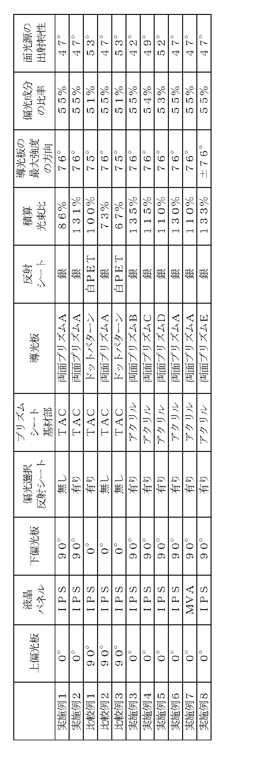
偏光選択反射シートは非常に高価であるので、液晶表示装置において偏光選択反射シートを削除することができれば、コスト、製造効率および薄型化のいずれの観点からも非常に有利である。一方で、良好な表示品位を維持するためには、偏光選択反射シートを用いる場合に対して80%以上の全光束を得る必要がある。ここで、表1から明らかなように、実施例1の液晶表示装置は、全光束の積算光束比が偏光選択反射シートを備える液晶表示装置の80%以上であり、偏光選択反射シートを備えなくとも、明るく良好な映像を表示できた。さらに、偏光選択反射シートを備える実施例2の液晶表示装置は、対応する従来の構成の液晶表示装置(比較例1)に対する積算光束比が134%となり、大幅に明るく、光の利用効率の高い表示装置となった。
実施例1と比較例2とを比較すると明らかなように、液晶表示装置の正面方向から見て、第2の偏光板14の透過軸方向と、プリズムシート30から出射する光(第2指向性光L2)の主たる偏光方向とを平行とすることにより、透過光量を増大させ、輝度を向上させることができた。 <Evaluation>
Since the polarization selective reflection sheet is very expensive, if the polarization selective reflection sheet can be eliminated from the liquid crystal display device, it is very advantageous from the viewpoints of cost, manufacturing efficiency, and thickness reduction. On the other hand, in order to maintain good display quality, it is necessary to obtain a total luminous flux of 80% or more as compared with the case of using the polarization selective reflection sheet. Here, as is clear from Table 1, in the liquid crystal display device of Example 1, the total luminous flux ratio is 80% or more of the liquid crystal display device including the polarization selective reflection sheet, and does not include the polarization selective reflection sheet. Both images were bright and good. Further, the liquid crystal display device of Example 2 including the polarization selective reflection sheet has a cumulative luminous flux ratio of 134% with respect to the corresponding conventional liquid crystal display device (Comparative Example 1), which is significantly brighter and has high light utilization efficiency. It became a display device.
As is clear from the comparison between Example 1 and Comparative Example 2, the transmission axis direction of the second
10 光源部
10a 点光源
11 反射板
12 液晶セル
13 第1の偏光板
14 第2の偏光板
15 液晶表示パネル
16 偏光選択反射シート
20 面光源装置
21 導光板
24 出光側単位光学要素
26 裏面側単位光学要素
30 プリズムシート
31 基材部
33 単位プリズム
34 第1斜面
35 第2斜面
DESCRIPTION OF SYMBOLS 1 Liquid
Claims (5)
- 観察者側に設けられる第1の偏光板と背面側に設けられる第2の偏光板との間に液晶セルを備える液晶表示パネルと、該液晶表示パネルを背面側から照明する面光源装置と、を備え、
該面光源装置は、
光源部と、
該光源部からの光を、該光源部に対向する入光面から入射させ、該液晶表示パネルと対向する出光面から、光の導光方向と略平行な面内において該出光面の法線方向から所定の角度をなす第1の方向に最大強度の指向性を有し、かつ、該面内で振動する偏光成分の比率が高い偏光光である第1指向性光を出射する導光板と、
該導光板より該液晶表示パネル側に配置され、該導光板側に凸となる柱状の単位プリズムが複数配列されたプリズム部を備え、該第1指向性光を、その偏光状態を実質的に維持しつつ該導光板の該出光面の法線方向から所定の角度内の第2の方向に指向した第2指向性光として出光するプリズムシートと、を備え、
該単位プリズムの稜線方向は、該導光板の該入光面に略平行であり、
該第2の偏光板の透過軸は、該第2指向性光の偏光方向と該導光板の光の導光方向に略平行しており、
該第2の偏光板の透過軸は、該第1の偏光板の透過軸と略直交している、
液晶表示装置。 A liquid crystal display panel including a liquid crystal cell between a first polarizing plate provided on the viewer side and a second polarizing plate provided on the back side; a surface light source device that illuminates the liquid crystal display panel from the back side; With
The surface light source device
A light source unit;
Light from the light source unit is incident from a light incident surface facing the light source unit, and from the light exit surface facing the liquid crystal display panel, the normal line of the light exit surface is within a plane substantially parallel to the light guide direction. A light guide plate that emits first directional light, which is polarized light having a maximum intensity directivity in a first direction that forms a predetermined angle from the direction and having a high ratio of polarization components that vibrate in the plane; ,
A prism unit disposed on the liquid crystal display panel side of the light guide plate and arranged with a plurality of columnar unit prisms protruding toward the light guide plate side, and the polarization direction of the first directional light is substantially reduced. A prism sheet that emits light as second directional light directed in a second direction within a predetermined angle from the normal direction of the light exit surface of the light guide plate while maintaining,
The ridge line direction of the unit prism is substantially parallel to the light incident surface of the light guide plate,
The transmission axis of the second polarizing plate is substantially parallel to the polarization direction of the second directional light and the light guide direction of the light of the light guide plate,
The transmission axis of the second polarizing plate is substantially orthogonal to the transmission axis of the first polarizing plate,
Liquid crystal display device. - 前記プリズムシートが、前記プリズム部より前記液晶表示パネル側に、該プリズム部を支持する基材部を備え、該基材部が実質的に光学的に等方性を有する、請求項1に記載の液晶表示装置。 The said prism sheet is equipped with the base material part which supports this prism part in the said liquid crystal display panel side from the said prism part, and this base material part has optical isotropy substantially. Liquid crystal display device.
- 前記第1指向性光が、前記光の導光方向と略平行な面内で振動する偏光成分を52%以上含む、請求項1または2に記載の液晶表示装置。 3. The liquid crystal display device according to claim 1, wherein the first directional light includes 52% or more of a polarization component that vibrates in a plane substantially parallel to the light guide direction.
- 前記導光板が光散乱剤を含有し、かつ、該導光板の裏面側に凸となる柱状の裏面側単位光学要素が、該導光板の前記入光面側から反対側の側面へ複数配列され、
前記単位プリズムの配列方向が、該裏面側単位光学要素の配列方向と略平行である、
請求項1から3のいずれかに記載の液晶表示装置。 The light guide plate contains a light scattering agent, and a plurality of columnar back side unit optical elements that are convex on the back side of the light guide plate are arranged from the light incident surface side to the opposite side surface of the light guide plate. ,
The arrangement direction of the unit prisms is substantially parallel to the arrangement direction of the back-side unit optical elements.
The liquid crystal display device according to claim 1. - 前記面光源装置と前記第1の偏光板との間に偏光選択反射シートをさらに備える、請求項1から4のいずれかに記載の液晶表示装置。
The liquid crystal display device according to claim 1, further comprising a polarization selective reflection sheet between the surface light source device and the first polarizing plate.
Priority Applications (4)
| Application Number | Priority Date | Filing Date | Title |
|---|---|---|---|
| CN201380009793.7A CN104246590B (en) | 2012-02-17 | 2013-02-14 | Liquid crystal display |
| EP13749648.5A EP2816400A4 (en) | 2012-02-17 | 2013-02-14 | Liquid crystal display device |
| US14/378,169 US9261640B2 (en) | 2012-02-17 | 2013-02-14 | Liquid crystal display apparatus |
| KR1020147022805A KR102050611B1 (en) | 2012-02-17 | 2013-02-14 | Liquid crystal display device |
Applications Claiming Priority (4)
| Application Number | Priority Date | Filing Date | Title |
|---|---|---|---|
| JP2012033285 | 2012-02-17 | ||
| JP2012-033285 | 2012-02-17 | ||
| JP2013020335A JP6377887B2 (en) | 2012-02-17 | 2013-02-05 | Liquid crystal display |
| JP2013-020335 | 2013-02-05 |
Publications (1)
| Publication Number | Publication Date |
|---|---|
| WO2013122155A1 true WO2013122155A1 (en) | 2013-08-22 |
Family
ID=48984264
Family Applications (1)
| Application Number | Title | Priority Date | Filing Date |
|---|---|---|---|
| PCT/JP2013/053550 WO2013122155A1 (en) | 2012-02-17 | 2013-02-14 | Liquid crystal display device |
Country Status (7)
| Country | Link |
|---|---|
| US (1) | US9261640B2 (en) |
| EP (1) | EP2816400A4 (en) |
| JP (1) | JP6377887B2 (en) |
| KR (1) | KR102050611B1 (en) |
| CN (1) | CN104246590B (en) |
| TW (1) | TWI566009B (en) |
| WO (1) | WO2013122155A1 (en) |
Cited By (1)
| Publication number | Priority date | Publication date | Assignee | Title |
|---|---|---|---|---|
| WO2021199652A1 (en) * | 2020-04-03 | 2021-10-07 | 株式会社ジャパンディスプレイ | Illumination device |
Families Citing this family (30)
| Publication number | Priority date | Publication date | Assignee | Title |
|---|---|---|---|---|
| EP3001094A4 (en) * | 2013-05-10 | 2016-11-23 | Kuraray Co | Lighting device |
| CN104848052A (en) | 2014-02-13 | 2015-08-19 | 扬升照明股份有限公司 | Backlight module |
| JP2015195181A (en) * | 2014-03-28 | 2015-11-05 | 大日本印刷株式会社 | Surface light source device and display device |
| KR20160138984A (en) * | 2014-04-01 | 2016-12-06 | 쓰리엠 이노베이티브 프로퍼티즈 컴파니 | Asymmetric turning film with multiple light sources |
| KR20170015300A (en) | 2014-05-30 | 2017-02-08 | 쓰리엠 이노베이티브 프로퍼티즈 컴파니 | Temporally multiplexing backlight with asymmetric turning film |
| US20170329180A1 (en) * | 2014-12-03 | 2017-11-16 | Sharp Kabushiki Kaisha | Lighting device, display device, and television device |
| CN106704566A (en) * | 2015-07-21 | 2017-05-24 | 比亚迪股份有限公司 | Luminous handle head and vehicle provided with luminous handle head |
| JP6618289B2 (en) * | 2015-07-23 | 2019-12-11 | スタンレー電気株式会社 | Surface light source device and prism sheet |
| CN107924083A (en) * | 2015-08-13 | 2018-04-17 | 3M创新有限公司 | Display including turning film and diffuser |
| CN106716012B (en) * | 2015-08-25 | 2020-03-27 | 日东树脂工业株式会社 | Method for manufacturing light guide plate |
| JP2017045641A (en) * | 2015-08-27 | 2017-03-02 | 大日本印刷株式会社 | Surface light source device and display device |
| CN105109168B (en) * | 2015-09-16 | 2017-05-03 | 梁志勇 | Manufacturing method of LED light guide plate provided with textures |
| US9921357B2 (en) * | 2016-06-21 | 2018-03-20 | Sharp Kabushiki Kaisha | Thin backlight with recycling to reduce the bezel width |
| JP2018036586A (en) | 2016-09-02 | 2018-03-08 | 日東電工株式会社 | Optical member |
| JP2018036585A (en) | 2016-09-02 | 2018-03-08 | 日東電工株式会社 | Optical member |
| US11307333B2 (en) * | 2017-01-04 | 2022-04-19 | 3M Innovative Properties Company | Asymmetric turning film with top-hat light output distributions |
| JP6500926B2 (en) * | 2017-03-14 | 2019-04-17 | オムロン株式会社 | Display device and game machine |
| US10401553B2 (en) * | 2017-03-21 | 2019-09-03 | Keiwa Inc. | Liquid crystal display device and turning film for liquid crystal display device |
| JP7098352B2 (en) * | 2017-03-21 | 2022-07-11 | 恵和株式会社 | Turning film for liquid crystal displays and liquid crystal displays |
| CN107037528A (en) * | 2017-04-19 | 2017-08-11 | 努比亚技术有限公司 | Light conducting plate structure, backlight module and display terminal |
| EP3525030B1 (en) * | 2017-04-25 | 2022-10-05 | LG Chem, Ltd. | Optical device |
| TWI657277B (en) * | 2018-03-06 | 2019-04-21 | 友達光電股份有限公司 | Display device |
| CN112424529B (en) * | 2019-05-14 | 2022-04-08 | 瑞仪(广州)光电子器件有限公司 | Light source structure, backlight module and display device |
| CN110361808B (en) | 2019-07-19 | 2021-03-23 | 京东方科技集团股份有限公司 | Light guide plate and manufacturing method thereof, backlight module and display device |
| JP7345336B2 (en) | 2019-09-20 | 2023-09-15 | 株式会社ジャパンディスプレイ | display device |
| CN110579903B (en) * | 2019-10-17 | 2023-04-14 | 京东方科技集团股份有限公司 | Array substrate, manufacturing method thereof, liquid crystal display panel and display device |
| CN111338128B (en) * | 2020-04-10 | 2022-11-22 | 马鞍山晶智科技有限公司 | Transparent light source system for display device |
| CN112327401A (en) * | 2020-09-28 | 2021-02-05 | 江苏瀚阳新材料科技有限公司 | High-brightness light guide plate and production process thereof |
| JP2022175312A (en) * | 2021-05-13 | 2022-11-25 | 株式会社ジャパンディスプレイ | Luminaire and display device |
| CN115097564B (en) * | 2022-07-14 | 2024-03-01 | 友达光电(昆山)有限公司 | Optical assembly and display device using same |
Citations (18)
| Publication number | Priority date | Publication date | Assignee | Title |
|---|---|---|---|---|
| JPH05169015A (en) | 1991-12-25 | 1993-07-09 | Dainippon Printing Co Ltd | Production of light diffusion sheet |
| JPH06265892A (en) | 1993-03-10 | 1994-09-22 | Asahi Glass Co Ltd | Illumination device and liquid crystal display device |
| JPH0749496A (en) * | 1992-10-09 | 1995-02-21 | Asahi Glass Co Ltd | Lighting system and liquid crystal display device |
| US5523863A (en) | 1988-10-19 | 1996-06-04 | Fergason; James L. | Controlled liquid crystal optical polarizer method and apparatus |
| US6049428A (en) | 1994-11-18 | 2000-04-11 | Optiva, Inc. | Dichroic light polarizers |
| JP2002031812A (en) | 2000-06-01 | 2002-01-31 | Hynix Semiconductor Inc | Fringe field switching mode liquid crystal display device |
| JP2004213019A (en) | 2003-01-03 | 2004-07-29 | Samsung Electronics Co Ltd | Light guide method and its system, and back light assembly having the same and liquid crystal display device |
| JP2004363062A (en) * | 2003-06-09 | 2004-12-24 | Enplas Corp | Light guide, plane shape light source device and image display apparatus |
| JP3874222B2 (en) | 1997-11-19 | 2007-01-31 | 株式会社エンプラス | Light source device |
| JP2007220347A (en) | 2006-02-14 | 2007-08-30 | Citizen Electronics Co Ltd | Variable prism light guide plate |
| JP2008262906A (en) | 2007-03-16 | 2008-10-30 | Dtmc:Kk | Back-light unit |
| JP2009037204A (en) | 2007-03-27 | 2009-02-19 | Dainippon Printing Co Ltd | Sheet-shaped optical member, resin composition for optical sheet, optical sheet and process for producing the same |
| WO2009104793A1 (en) * | 2008-02-21 | 2009-08-27 | シャープ株式会社 | Light guide body, backlight system and portable terminal |
| JP2010003460A (en) * | 2008-06-18 | 2010-01-07 | Teijin Ltd | Polarizing light guide plate assembly, and liquid crystal display |
| JP2010284840A (en) | 2009-06-10 | 2010-12-24 | Kaneka Corp | Film attached with coating layer, polarizer protecting film and polarization plate using polarizer protecting film |
| JP4673463B2 (en) | 1999-12-03 | 2011-04-20 | 大日本印刷株式会社 | Liquid crystal display device |
| JP2011090832A (en) | 2009-10-21 | 2011-05-06 | Mitsubishi Electric Corp | Planar light source, and liquid crystal display |
| JP2012033341A (en) * | 2010-07-29 | 2012-02-16 | Dainippon Printing Co Ltd | Plane light source device, liquid crystal display, and optical member |
Family Cites Families (17)
| Publication number | Priority date | Publication date | Assignee | Title |
|---|---|---|---|---|
| TW594115B (en) * | 1992-10-09 | 2004-06-21 | Asahi Glass Co Ltd | A liquid crystal display device and an illumination device for a direct viewing type display element |
| JP3219943B2 (en) * | 1994-09-16 | 2001-10-15 | 株式会社東芝 | Planar direct-view display device |
| JP3442247B2 (en) * | 1996-02-01 | 2003-09-02 | 三菱レイヨン株式会社 | Light guide for surface light source element and surface light source element |
| US6027220A (en) | 1996-11-19 | 2000-02-22 | Enplas Corporation | Surface light source device outputting polarized frontal illumination light |
| CN2586982Y (en) * | 2002-12-03 | 2003-11-19 | 鸿富锦精密工业(深圳)有限公司 | Back light system |
| CN101142442A (en) * | 2005-03-17 | 2008-03-12 | 富士通株式会社 | Lighting apparatus and LCD device |
| TW200905306A (en) * | 2007-07-16 | 2009-02-01 | Au Optronics Corp | Backlight module and liquid crystal display comprising the same |
| WO2009141953A1 (en) * | 2008-05-20 | 2009-11-26 | シャープ株式会社 | Liquid crystal display device |
| JP2010177047A (en) * | 2009-01-29 | 2010-08-12 | Hitachi Maxell Ltd | Backlight unit, prism sheet and liquid crystal display unit |
| JP2010262827A (en) * | 2009-05-07 | 2010-11-18 | Mitsubishi Rayon Co Ltd | Surface light source device and liquid crystal display device |
| JP5343752B2 (en) * | 2009-07-31 | 2013-11-13 | 大日本印刷株式会社 | Light guide plate, light guide plate manufacturing method, surface light source device, and liquid crystal display device |
| JP2011107248A (en) * | 2009-11-13 | 2011-06-02 | Hitachi Displays Ltd | Liquid crystal display device |
| EP2508939A4 (en) * | 2009-11-30 | 2013-11-13 | Nitto Denko Corp | Liquid crystal display device |
| JP5055398B2 (en) * | 2010-03-12 | 2012-10-24 | 株式会社ジャパンディスプレイイースト | Illumination device and liquid crystal display device |
| JP5533310B2 (en) * | 2010-06-15 | 2014-06-25 | 大日本印刷株式会社 | Light guide plate, surface light source device and display device |
| JP5686135B2 (en) * | 2010-07-12 | 2015-03-18 | 大日本印刷株式会社 | Display device |
| KR101348565B1 (en) * | 2012-01-13 | 2014-01-16 | 영남대학교 산학협력단 | Backlight unit and liquid display device that contains it |
-
2013
- 2013-02-05 JP JP2013020335A patent/JP6377887B2/en active Active
- 2013-02-14 EP EP13749648.5A patent/EP2816400A4/en not_active Withdrawn
- 2013-02-14 KR KR1020147022805A patent/KR102050611B1/en active IP Right Grant
- 2013-02-14 CN CN201380009793.7A patent/CN104246590B/en active Active
- 2013-02-14 WO PCT/JP2013/053550 patent/WO2013122155A1/en active Application Filing
- 2013-02-14 US US14/378,169 patent/US9261640B2/en active Active
- 2013-02-18 TW TW102105694A patent/TWI566009B/en active
Patent Citations (18)
| Publication number | Priority date | Publication date | Assignee | Title |
|---|---|---|---|---|
| US5523863A (en) | 1988-10-19 | 1996-06-04 | Fergason; James L. | Controlled liquid crystal optical polarizer method and apparatus |
| JPH05169015A (en) | 1991-12-25 | 1993-07-09 | Dainippon Printing Co Ltd | Production of light diffusion sheet |
| JPH0749496A (en) * | 1992-10-09 | 1995-02-21 | Asahi Glass Co Ltd | Lighting system and liquid crystal display device |
| JPH06265892A (en) | 1993-03-10 | 1994-09-22 | Asahi Glass Co Ltd | Illumination device and liquid crystal display device |
| US6049428A (en) | 1994-11-18 | 2000-04-11 | Optiva, Inc. | Dichroic light polarizers |
| JP3874222B2 (en) | 1997-11-19 | 2007-01-31 | 株式会社エンプラス | Light source device |
| JP4673463B2 (en) | 1999-12-03 | 2011-04-20 | 大日本印刷株式会社 | Liquid crystal display device |
| JP2002031812A (en) | 2000-06-01 | 2002-01-31 | Hynix Semiconductor Inc | Fringe field switching mode liquid crystal display device |
| JP2004213019A (en) | 2003-01-03 | 2004-07-29 | Samsung Electronics Co Ltd | Light guide method and its system, and back light assembly having the same and liquid crystal display device |
| JP2004363062A (en) * | 2003-06-09 | 2004-12-24 | Enplas Corp | Light guide, plane shape light source device and image display apparatus |
| JP2007220347A (en) | 2006-02-14 | 2007-08-30 | Citizen Electronics Co Ltd | Variable prism light guide plate |
| JP2008262906A (en) | 2007-03-16 | 2008-10-30 | Dtmc:Kk | Back-light unit |
| JP2009037204A (en) | 2007-03-27 | 2009-02-19 | Dainippon Printing Co Ltd | Sheet-shaped optical member, resin composition for optical sheet, optical sheet and process for producing the same |
| WO2009104793A1 (en) * | 2008-02-21 | 2009-08-27 | シャープ株式会社 | Light guide body, backlight system and portable terminal |
| JP2010003460A (en) * | 2008-06-18 | 2010-01-07 | Teijin Ltd | Polarizing light guide plate assembly, and liquid crystal display |
| JP2010284840A (en) | 2009-06-10 | 2010-12-24 | Kaneka Corp | Film attached with coating layer, polarizer protecting film and polarization plate using polarizer protecting film |
| JP2011090832A (en) | 2009-10-21 | 2011-05-06 | Mitsubishi Electric Corp | Planar light source, and liquid crystal display |
| JP2012033341A (en) * | 2010-07-29 | 2012-02-16 | Dainippon Printing Co Ltd | Plane light source device, liquid crystal display, and optical member |
Non-Patent Citations (4)
| Title |
|---|
| "Ekisho", vol. 2, 1998, THE JAPANESE LIQUID CRYSTAL SOCIETY PUBLISHING, pages: 303 - 316 |
| "Monthly Display", July 1997, TECHNO TIMES CO., LTD., pages: 83 - 88 |
| See also references of EP2816400A4 * |
| SID (SOCIETY FOR INFORMATION DISPLAY, 2001, pages 484 - 487 |
Cited By (3)
| Publication number | Priority date | Publication date | Assignee | Title |
|---|---|---|---|---|
| WO2021199652A1 (en) * | 2020-04-03 | 2021-10-07 | 株式会社ジャパンディスプレイ | Illumination device |
| JP7346719B2 (en) | 2020-04-03 | 2023-09-19 | 株式会社ジャパンディスプレイ | lighting equipment |
| US11934001B2 (en) | 2020-04-03 | 2024-03-19 | Japan Display Inc. | Lighting device having a light guide with prism array formed thereon and a prism sheet and white LEDs |
Also Published As
| Publication number | Publication date |
|---|---|
| CN104246590B (en) | 2017-10-13 |
| EP2816400A4 (en) | 2015-11-18 |
| TWI566009B (en) | 2017-01-11 |
| JP2013190778A (en) | 2013-09-26 |
| KR102050611B1 (en) | 2019-11-29 |
| EP2816400A1 (en) | 2014-12-24 |
| TW201339703A (en) | 2013-10-01 |
| CN104246590A (en) | 2014-12-24 |
| KR20140140538A (en) | 2014-12-09 |
| US20150029442A1 (en) | 2015-01-29 |
| JP6377887B2 (en) | 2018-08-22 |
| US9261640B2 (en) | 2016-02-16 |
Similar Documents
| Publication | Publication Date | Title |
|---|---|---|
| JP6377887B2 (en) | Liquid crystal display | |
| JP6202828B2 (en) | Liquid crystal display | |
| JP5913689B2 (en) | Optical member, polarizing plate set and liquid crystal display device | |
| KR102118231B1 (en) | Optical member, polarizing plate set and liquid crystal display device | |
| US20150277012A1 (en) | Optical member, polarizing plate set, and liquid crystal display apparatus | |
| KR102292765B1 (en) | Optical member, polarizing plate set, and liquid crystal display apparatus | |
| US20140009960A1 (en) | Backlight device | |
| US9638955B2 (en) | Liquid crystal display device and polarizing plate with a condensing element | |
| TW201816434A (en) | Optical member | |
| KR102315475B1 (en) | Optical member | |
| KR102020837B1 (en) | Back light unit and display divice |
Legal Events
| Date | Code | Title | Description |
|---|---|---|---|
| 121 | Ep: the epo has been informed by wipo that ep was designated in this application |
Ref document number: 13749648 Country of ref document: EP Kind code of ref document: A1 |
|
| WWE | Wipo information: entry into national phase |
Ref document number: 14378169 Country of ref document: US |
|
| WWE | Wipo information: entry into national phase |
Ref document number: 2013749648 Country of ref document: EP |
|
| ENP | Entry into the national phase |
Ref document number: 20147022805 Country of ref document: KR Kind code of ref document: A |
|
| NENP | Non-entry into the national phase |
Ref country code: DE |