WO2013140438A1 - Sensor device - Google Patents

Sensor device Download PDF

Info

Publication number
WO2013140438A1
WO2013140438A1 PCT/JP2012/001909 JP2012001909W WO2013140438A1 WO 2013140438 A1 WO2013140438 A1 WO 2013140438A1 JP 2012001909 W JP2012001909 W JP 2012001909W WO 2013140438 A1 WO2013140438 A1 WO 2013140438A1
Authority
WO
WIPO (PCT)
Prior art keywords
sensor
counter
information
request
sensor device
Prior art date
Application number
PCT/JP2012/001909
Other languages
French (fr)
Japanese (ja)
Inventor
希元 鄭
Original Assignee
株式会社日立製作所
Priority date (The priority date is an assumption and is not a legal conclusion. Google has not performed a legal analysis and makes no representation as to the accuracy of the date listed.)
Filing date
Publication date
Application filed by 株式会社日立製作所 filed Critical 株式会社日立製作所
Priority to CN201280070800.XA priority Critical patent/CN104246450A/en
Priority to EP12871876.4A priority patent/EP2829849A4/en
Priority to JP2014505792A priority patent/JP5775964B2/en
Priority to KR1020147023369A priority patent/KR20140119139A/en
Priority to US14/384,169 priority patent/US20150036782A1/en
Priority to PCT/JP2012/001909 priority patent/WO2013140438A1/en
Publication of WO2013140438A1 publication Critical patent/WO2013140438A1/en
Priority to IN7641DEN2014 priority patent/IN2014DN07641A/en

Links

Images

Classifications

    • GPHYSICS
    • G01MEASURING; TESTING
    • G01DMEASURING NOT SPECIALLY ADAPTED FOR A SPECIFIC VARIABLE; ARRANGEMENTS FOR MEASURING TWO OR MORE VARIABLES NOT COVERED IN A SINGLE OTHER SUBCLASS; TARIFF METERING APPARATUS; MEASURING OR TESTING NOT OTHERWISE PROVIDED FOR
    • G01D21/00Measuring or testing not otherwise provided for

Definitions

  • the present invention relates to a sensor device that measures an external physical quantity. More specifically, the present invention relates to a sensor device that receives physical quantity acquisition requests from a plurality of request sources.
  • ITS intelligent transportation systems
  • Patent Document 1 shows an example of the information collection method.
  • Japanese Patent Laid-Open No. 2004-151867 makes a request for acquiring sensor information at a desired position from a remote post connected to a fixed network by a query, and proxies a mobile object that has registered position information that matches the area specified by the query.
  • a query transferred from a device is received, a technique for transmitting sensor information received by the mobile body to a remote post that is a transmission source of the received query via a fixed network is disclosed. It has been shown that by using such an information collection method, a specific request source can collect information from sensors in a specific area in a specific time zone.
  • Patent Document 2 discloses a method for collecting information by designating a specific sensor. Specifically, a method in which a moving reader collects identification information of ubiquitous nodes such as RFIDs located in the communication area, and requests information transmission by designating a specific ubiquitous node based on the identification information It is shown. It is described that by applying this method, it is possible to prevent information collision at the time of transmission information transmission and to reduce power consumption because information is transmitted only when a request is received.
  • sensors for management For example, different facilities of management companies such as water and sewage systems and gas pipes are embedded in roads, road management companies install sensors for road management, and water and sewage management companies and gas pipe management companies Install sensors for management. Although these sensors have different installation purposes and request sources, they often measure common physical quantities such as temperature, humidity, and vibration.
  • An object of the present invention is to provide a sensor device suitable for such a sensor system.
  • a typical example of means for solving the problems according to the present invention is a sensor device, which is a physical quantity detection unit that measures an external physical quantity, and receives physical quantity acquisition requests from a plurality of external request sources.
  • FIG. 1 is an overall configuration schematic diagram of a counter-equipped sensor in Embodiment 1.
  • FIG. It is a block diagram of the counter part of the sensor with a counter in Example 1.
  • FIG. It is a correlation diagram explaining the operation of the sensor with a counter in the second embodiment.
  • 6 is a flowchart of information of a sensor with a counter according to the second embodiment. It is a block diagram of the information transmission log
  • the constituent elements are not necessarily indispensable unless otherwise specified or apparently essential in principle.
  • FIG. 1 is a schematic diagram showing the overall configuration of a counter-equipped sensor S1 as an example of a sensor device according to the present invention.
  • the sensor with counter S1 of this embodiment measures physical quantities necessary for maintaining and repairing roads and infrastructure such as buildings, bridges, water and sewage pipes, and gas pipes such as temperature, pressure, speed, position, acceleration and angular velocity.
  • a physical quantity detection unit 1 that performs identification, an ID holding unit 2 for identifying a sensor, an information transmission history storage unit 3 whose value changes in conjunction with an acquisition request from the outside, reception of an acquisition request from the outside, The measurement value from the physical quantity detection unit 1, the ID of the sensor, and the transmission of information transmission history information are configured by an input / output unit 4 that performs wired or wireless transmission.
  • the physical quantity detection unit 1 includes a temperature detection unit based on a known principle such as a thermistor or a thermocouple type, and an external pressure fluctuation as a deformation amount of a diaphragm or the like as a change in capacitance or a change in electrical resistance value.
  • Pressure detection unit to detect humidity detection unit that utilizes changes in dielectric constant and conductivity due to moisture absorption of moisture sensor, speed detection unit using Doppler phenomenon, GPS positioning or stored in advance in sensor All or one of position information, an acceleration and angular velocity detector that detects displacement of the movable body by a change in capacitance, and a gas detector that measures a change in conductivity caused by a chemical reaction between a specific gas and a catalyst.
  • the physical quantities detected by these detectors are stored in a nonvolatile memory (not shown).
  • the sensor ID holding unit 2 is a non-volatile memory that stores a unique value for identifying the sensor, and the sensor owner uses the value stored in the sensor ID holding unit 2 to install the sensor. And manage the installation time.
  • FIG. 2 is a schematic diagram showing the configuration of the counter 30.
  • the counter 30 is configured as a non-volatile memory 31 that stores counter information even when power is lost, a temporary memory 32, and a counter circuit 33 that uses a flip-flop circuit.
  • the counter information stored in the nonvolatile memory 31 is dumped to the cache 32 which is a temporary storage location.
  • the counter circuit 33 increments the number stored in the cache 32 by one, and the value in the cache 32 is stored in the nonvolatile memory 31 again.
  • the configuration of the non-volatile memory 31 including the flip-flop type counter circuit 33, the cache 32, and the flash memory is shown, but the gist of the present invention is the external acquisition request. Accordingly, the value inside the sensor may be changed by some means and stored, and the value is not limited to the configuration of the counter 30 shown in FIG.
  • the counter 30 illustrated in FIG. 2 counts and stores the total number of times of receiving physical quantity acquisition requests from a plurality of request sources without distinguishing from which request source the acquisition request is received. And The effect of the sensor S1 having the counter 30 will be described later. Further, as described in the second embodiment, it is possible to further provide a counter that distinguishes request sources and counts and stores the number of times an acquisition request is received for each request source.
  • the input / output unit 4 receives an acquisition request from the outside by wired or wireless communication, and both the information on the physical quantity measured by the physical detection unit 1 and the value stored in the ID holding unit 2 are stored in the counter 30.
  • the value stored in the nonvolatile memory 31 is transmitted to the request source by wired or wireless communication.
  • the request source corresponds to a mobile body shown in the information collection technique of Patent Document 1. Specifically, it is an information collection terminal (such as a car navigation system having a two-way communication function) attached to a running car, or a mobile phone carried by a walking person. Information collected by these information collection terminals is transmitted to a remote host or the like via the fixed network disclosed in the prior art.
  • the remote posts correspond to management companies that manage roads, pipelines, and the like using the sensors S1.
  • information may be collected by the method disclosed in Patent Document 1 or Patent Document 2 cited in the present application, but the sensor with counter S1 of the first embodiment is similar to Patent Document 1 and Patent Document 2. It is not limited by the information collection method.
  • the sensor device includes a counter that does not distinguish from which request source the acquisition request is, as described above.
  • This counter functions as an absolute counter for the sensor device. Therefore, the information stored in the counter can also be used when setting the performance lifetime of the sensor device.
  • the sensor S1 is subject to deterioration of electronic components such as capacitors, precision resistors, various electronic circuits including transistors and OP amplifiers, and loosened fixed parts due to repeated activation and repeated wireless transmission. Changes in the mounting form over time occur. When these changes exceed a certain level, the sensor S1 reaches its performance life, but the value of the counter 30 is used as a judgment criterion, and the same as when the battery is replaced based on this information. The sensor S1 can be replaced.
  • the sensor S1 is driven by a battery. In this case, the sensor S1 normally waits in the slip mode to minimize battery consumption. In this state, when an acquisition request from the outside is input to the input / output unit 4 of the sensor S1, the sensor S1 changes to the start mode and transmits information to the request source. At this time, the power consumption required for one start-up and information transmission can be easily calculated or measured, so it is possible to calculate how many times information transmission and start-up is possible from the capacity of the installed battery. it can.
  • the management company responsible for maintenance / repair of the sensor S1 can replace the sensor S1 in the jurisdiction or the battery of the sensor S1 while referring to the counter information on site.
  • the battery replacement time can be known from the value of the second counter circuit by setting the value of the second counter circuit to 0 after the battery replacement.
  • the sensor with a counter can install an environment-embedded sensor in a specific area where a plurality of infrastructure management companies overlap, and can access each other sensor independently (sharing the sensor), Furthermore, the invention effect can be exhibited when the sensor maintenance / repair is performed by a sensor repair company different from the infrastructure management company for each area. Detailed operation modes will be described in detail in another embodiment.
  • FIG. 3 is a diagram schematically illustrating a main configuration related to operations such as sharing, maintenance, and repair of the counter-equipped sensor according to the present embodiment.
  • a plurality of infrastructure management companies 113 and 114 are assumed.
  • the sensor device according to the present embodiment is used as the environment-embedded sensor 121.
  • 123, 125, 127, 129 and 122, 124, 126, 128, 130 are assumed to be installed in area 1 and area 2.
  • the management company 113 is a road business company and the management company 114 is a water and sewage and gas business company in order to make it easy to imagine the contents of the invention. In general, water and sewage pipes and gas pipes are often buried under or beside a road.
  • the management companies 113 and 114 install the environment-embedded sensors 121 to 130 for the purpose of collecting information on maintenance / repair of roads or pipes, but in order to obtain highly accurate information, it is necessary to install many sensors. However, installing and managing a large number of sensors independently by each company requires enormous initial installation costs and maintenance / management costs.
  • Information required for road maintenance / repair requires environmental information including temperature, humidity, and vibration.
  • environmental information including temperature, humidity, and vibration.
  • gas leak detection and temperature / humidity / vibration There are many items in common with information necessary for road management. Therefore, if the management companies 113 and 114 share the sensors 121 to 130, more accurate information can be obtained while suppressing initial installation costs and sensor maintenance / management (operation) costs. .
  • area 1 and area 2 indicate a region of about several meters to several tens of meters, which is a communicable distance between the mobile bodies 131 and 132 and the environment-embedded sensors 121 to 130, and the sensors.
  • area 1 and area 2 shown in FIG. 3 indicate a region of about several meters to several tens of meters, which is a communicable distance between the mobile bodies 131 and 132 and the environment-embedded sensors 121 to 130, and the sensors
  • a plurality of infrastructure management companies install environmentally-embedded sensors (121-130) in specific areas (area 1, area 2) where business jurisdictions overlap, and are independent of each other. It is possible to access (sharing sensors), and maintenance / repair of the sensors is performed for each area (area 1, area 2) by sensor repair companies 141, 142 (illustrated) different from the infrastructure management companies 113, 114. Details of the role of the counter-equipped sensor in the case of (no) will be described.
  • FIG. 4 is a correlation diagram for explaining the flow of measurement information and the sensor with counter S2 in the present embodiment. Details will be described together with the operation diagram of the counter-equipped sensor S2 in FIG. 3 and the configuration diagram of the information transmission history storage unit 3 in FIG.
  • the infrastructure management companies 113 and 114 transmit the request source IDs (113 and 114), the areas (area 1 and area 2) in which environmental information is to be measured, and the time zone to the gateways 134 and 135 that have contracts.
  • the gateways 134 and 135 correspond to locations where mobile units 131 and 132, which will be described later, such as a mobile phone company are grasped.
  • the mobile units 131 and 132 that are running or walking in the specified time zone (area 1 and area 2) in the specified time zone.
  • the ID of the gateway 134 or 135 or the ID of the infrastructure management company 113 or 114 that is the request source and the corresponding mobile body ID (131 or 132) are transmitted.
  • the mobile units 131 and 132 request information from the sensors by transmitting the IDs of the gateways 134 and 135 or the IDs of the infrastructure management companies 113 and 114 that are the request sources as an acquisition request to the environment embedded sensor.
  • the embedded environment sensors 121 to 130 have the IDs of the gateways 134 and 135 transmitted from the mobile units 131 and 132 or the IDs of the infrastructure management companies 113 and 114 that are the request sources as shown in FIG. If the information is registered in the access right determination unit 10 which is a non-volatile memory that stores each ID of each request source, the counters 40 to N0 corresponding to the request source are provided. The counter T0 for recording the total number of accesses is incremented by one, and the value stored in the sensor ID holding unit 2, the environmental measurement value from the physical quantity detection unit 1, and the counter information are transferred to the mobile unit 131, Send to 132.
  • the mobile units 131 and 132 may include information from sensors embedded in the mobile units 131 and 132, time information, and IDs of the mobile units 131 and 132, as necessary, together with information from the environment-embedded sensors 121 to 130. Reply to the gateways 134 and 135.
  • the gateways 134 and 135 add the IDs of the gateways 134 and 135 to the information from the sensors 121 to 130 and the information from the mobile units 131 and 132, and send them back to the infrastructure management companies 113 and 114 that are the request sources. To do.
  • the sensor device calculates the number of times the acquisition request is received for each of the plurality of request sources in addition to the counter T0 that counts and stores the total number of times the acquisition requests are received from the plurality of request sources. It has a plurality of counters 40 to N0 for counting and storing. With such a feature, while it is possible to measure the lifetime of the sensor device by the value stored in the counter T0, the information amount can be charged to each request source by the counters 40 to N0.
  • the infrastructure management companies 113 and 114 acquire environmental information in a necessary time zone of a necessary place while sharing each other's sensors. be able to.
  • each infrastructure management company 113 and 114 can access the partner's sensor independently of each other, it is possible to use the partner's sensor without leaking information even if there is no competition relationship or information exchange. Environmental data can be collected.
  • the access right determination unit 10 of the information transmission history storage unit 3 shown in FIG. 5 registers an ID and a counter corresponding to the ID added later based on information from outside the sensor device, although not shown. Alternatively, unnecessary IDs and corresponding counters can be deleted. Therefore, when the access right to the sensor is given to a new infrastructure management company or the like, a new ID may be registered in the access right determination unit 10.
  • the third and fourth sensors are repaired for each area (area 1, area 2) for the environment-embedded sensors 121, 123, 125, 127, and 129 and the sensors 122, 124, 126, 128, and 130 that have different owners.
  • the case where the management company manages is explained.
  • a plurality of infrastructure managers 113 and 114 perform sensor repair work for each area (area 1 and area 2), specialized sensor repair companies 141 and 142 ( (Not shown).
  • the sensor repair companies 141 and 142 receive information necessary for sensor replacement and repair (battery replacement) from the infrastructure management companies 113 and 114, and perform actual work.
  • the access history corresponding to the sensor ID is stored in the infrastructure management. Complicated procedures such as sharing between the companies 113 and 114 are required.
  • the counter information it is only necessary to exchange more than the number instructed by the infrastructure management companies 113 and 114 in advance, so that maintenance and management of the sensor can be performed even without complicated work instructions. Can do.
  • the counter-equipped sensor S2 of the present embodiment can achieve the same effect as the counter information described in the first embodiment.
  • S1 Sensor with counter
  • S2 Sensor with counter
  • 1 Physical quantity detection unit
  • 2 ID holding unit
  • 3 Information transmission history storage unit
  • 4 Input / output unit
  • 10 Access right determination unit
  • 30 Counter, 31 : Non-volatile memory, 32: cache, 33: counter circuit
  • 40 counter, 41: non-volatile memory, 42: cache, 43: counter circuit
  • N2 cache
  • N3 counter circuit
  • T0 Counter
  • T1 Non-volatile memory
  • T2 Cache
  • T3 Counter circuit
  • 111 Fixed network
  • 113 Infrastructure management company
  • 114 Infrastructure management company
  • 121-130 Environment embedded sensor
  • 131 Mobile body
  • 132 Movement Body: 134: Gateway
  • 135 Gateway
  • 141 Sensor repair company
  • 142 Sensor repair company.

Abstract

In order to provide a suitable sensor device for a sensor system in which a plurality of request sources request the acquisition of information for the same sensor, the sensor device is provided with a physical mass sensing unit (1) for measuring an external physical mass, an input-output unit (4) for receiving physical mass acquisition requests from the external plurality of request sources, and a first counter (3) for counting and storing the total number of times the input/output unit receives an acquisition request from the plurality of request sources. The input-output unit transmits the physical mass and a value stored by the first counter to the request source of the acquisition request.

Description

センサデバイスSensor device
 本発明は、外部の物理量を測定するセンサデバイスに関する。より具体的には、複数の要求元から物理量の取得要求を受信するセンサデバイスに関する。 The present invention relates to a sensor device that measures an external physical quantity. More specifically, the present invention relates to a sensor device that receives physical quantity acquisition requests from a plurality of request sources.
 スマートシティや高度道路交通システム(ITS)の推進などによって、環境埋め込みセンサの更なる普及が期待される。その中、例えば道路、建物、線路、駅、上下水道管、パイプライン、または空港等において広範囲に分散したセンサからの情報を効率的に収集する方法が提案されている。 The spread of environmentally-embedded sensors is expected due to the promotion of smart cities and intelligent transportation systems (ITS). Among them, for example, a method for efficiently collecting information from sensors widely distributed in a road, a building, a railroad, a station, a water and sewage pipe, a pipeline, or an airport has been proposed.
 例えば、特許文献1には、前記情報収集方法の一例が示されている。特許文献1には、固定網に接続された遠隔ポストから所望位置のセンサの情報の取得要求をクエリで行い、このクエリで指定されるエリアに一致する位置情報を登録した移動体に対してプロキシ装置から転送されるクエリを受信した際に、当該移動体で受信されたセンサ情報を、その受信クエリの送信元の遠隔ポストへ固定網を介して送信する技術が開示されている。このような情報収集方法を用いることで、特定の要求元が特定時間帯の特定エリアのセンサからの情報を収集することが可能であることが示されている。 For example, Patent Document 1 shows an example of the information collection method. Japanese Patent Laid-Open No. 2004-151867 makes a request for acquiring sensor information at a desired position from a remote post connected to a fixed network by a query, and proxies a mobile object that has registered position information that matches the area specified by the query. When a query transferred from a device is received, a technique for transmitting sensor information received by the mobile body to a remote post that is a transmission source of the received query via a fixed network is disclosed. It has been shown that by using such an information collection method, a specific request source can collect information from sensors in a specific area in a specific time zone.
 特許文献2には、特定センサを指定して情報を収集する方法が示されている。具体的には、移動するリーダが、その通信エリア内に位置するRFIDなどのユビキタスノードの識別情報を収集し、前記識別情報に基づいて、特定のユビキタスノードを指定して情報送信を要求する方法が示されている。この方法を適用することで、発信情報送信時の情報の衝突を防げることと、要求を受けた場合に限り情報を送信するので電力の消費量を低減できると記載されている。 Patent Document 2 discloses a method for collecting information by designating a specific sensor. Specifically, a method in which a moving reader collects identification information of ubiquitous nodes such as RFIDs located in the communication area, and requests information transmission by designating a specific ubiquitous node based on the identification information It is shown. It is described that by applying this method, it is possible to prevent information collision at the time of transmission information transmission and to reduce power consumption because information is transmitted only when a request is received.
特開2004-362267号JP 2004-362267 A 特開2006-304168号JP 2006-304168 A
 しかしながら、同一のセンサに対し複数の要求元が情報を取得要求するセンサシステムについては、報告例が見つからない。特に、隣接した場所に複数の要求元が違う目的のためにほぼ同じ情報を出力するセンサを設置する際の課題や、膨大なセンサの使用に伴うセンサの維持管理の課題については、未だに報告例が見つからない。 However, no report example is found for a sensor system in which a plurality of requesters request acquisition of information from the same sensor. In particular, there are still reports on issues related to installing sensors that output almost the same information for the purpose of different requesters in adjacent locations, and sensor maintenance issues associated with the use of a vast amount of sensors. Is not found.
 例えば、道路には上下水道やガス配管などの管理会社の異なる設備が埋設され、道路管理会社は道路の管理のためにセンサを設置し、上下水道管理会社とガス配管の管理会社は上下水道の管理のためにセンサを設置する。これらのセンサは設置目的と要求元は違うものの、夫々温度や湿度、振動等の共通の物理量を測る場合が多い。 For example, different facilities of management companies such as water and sewage systems and gas pipes are embedded in roads, road management companies install sensors for road management, and water and sewage management companies and gas pipe management companies Install sensors for management. Although these sensors have different installation purposes and request sources, they often measure common physical quantities such as temperature, humidity, and vibration.
 また、当該センサを環境に埋め込む場合は、電源や出力信号線などの配線工事が大変な場合が多く、最近では電池駆動で無線通信による測定情報の送受信方式を採用しているものも多い。しかし、電池式センサの場合、いずれ電池の交換が必要となるため、定期的なセンサの維持・補修が必要となる。また、センサの使用頻度や使用期間によっては、センサ性能の劣化による測定情報の信頼性劣化も問題となる。さらに、互いに情報が共有されていない複数の要求元が同じセンサにアクセスする場合は、どれだけセンサが使われているのかを把握することが困難である。その上、センサの取替え工事の場合においても、センサの設置場所や設置時期などの履歴をセンサごとに長期間にわたって管理し、膨大な数のセンサの中でどのセンサを交換するかを細かく指示する必要がある。 Also, when embedding the sensor in the environment, wiring work such as power supply and output signal line is often difficult, and recently, there are many that employ a battery-driven measurement information transmission / reception method by wireless communication. However, in the case of a battery-type sensor, since it is necessary to replace the battery, it is necessary to maintain and repair the sensor periodically. Further, depending on the use frequency and use period of the sensor, deterioration of reliability of measurement information due to deterioration of sensor performance becomes a problem. Furthermore, when a plurality of requesters whose information is not shared with each other accesses the same sensor, it is difficult to grasp how much the sensor is used. In addition, even in the case of sensor replacement work, the history of sensor installation location and installation time, etc. is managed for each sensor over a long period of time, and detailed instructions are given as to which sensor to replace among a vast number of sensors. There is a need.
 このように、複数の要求元が同一のセンサに情報の取得要求をするセンサシステムにおいては、従来は考慮されていなかった課題を考慮する必要がある。本発明の目的は、係るセンサシステムに好適なセンサデバイスを提供することである。 As described above, in a sensor system in which a plurality of requesters request acquisition of information from the same sensor, it is necessary to consider a problem that has not been considered in the past. An object of the present invention is to provide a sensor device suitable for such a sensor system.
 本願発明による課題を解決する手段のうち代表的なものを例示すれば、センサデバイスであって、外部の物理量を測定する物理量検知部と、外部の複数の要求元から物理量の取得要求を受信する入出力部と、入出力部が複数の要求元から取得要求を受信した回数の合計を計数し記憶する第1カウンタと、を有し、入出力部は、取得要求の要求元に対し、物理量および第1カウンタが記憶する値を送信することを特徴とする。 A typical example of means for solving the problems according to the present invention is a sensor device, which is a physical quantity detection unit that measures an external physical quantity, and receives physical quantity acquisition requests from a plurality of external request sources. An input / output unit, and a first counter that counts and stores the total number of times that the input / output unit has received acquisition requests from a plurality of request sources. And a value stored in the first counter is transmitted.
 本願発明によれば、複数の要求元が同一のセンサに情報の取得要求をするセンサシステムに対し、より好適なセンサデバイスを提供しうる。 According to the present invention, it is possible to provide a more suitable sensor device for a sensor system in which a plurality of requesters request acquisition of information from the same sensor.
実施例1におけるカウンタ付センサの全体構成模式図である。1 is an overall configuration schematic diagram of a counter-equipped sensor in Embodiment 1. FIG. 実施例1におけるカウンタ付センサのカウンタ部の構成図である。It is a block diagram of the counter part of the sensor with a counter in Example 1. FIG. 実施例2におけるカウンタ付センサの運用を説明する相関図である。It is a correlation diagram explaining the operation of the sensor with a counter in the second embodiment. 実施例2におけるカウンタ付センサの情報の流れ図である。6 is a flowchart of information of a sensor with a counter according to the second embodiment. 実施例2におけるカウンタ付センサの情報送信履歴保管部の構成図である。It is a block diagram of the information transmission log | history storage part of the sensor with a counter in Example 2. FIG.
 以下の実施例においては便宜上その必要があるときは、複数のセクションまたは実施の形態に分割して説明するが、特に明示した場合を除き、それらはお互いに無関係なものではなく、一方は他方の一部または全部の変形例、詳細、補足説明等の関係にある。 In the following examples, when it is necessary for the sake of convenience, the description will be divided into a plurality of sections or embodiments. However, unless otherwise specified, they are not irrelevant to each other, and one is the other. Some or all of the modifications, details, supplementary explanations, and the like are related.
 また、以下の実施例において、要素の数等(個数、数値、量、範囲等を含む)に言及する場合、特に明示した場合および原理的に明らかに特定の数に限定される場合等を除き、その特定の数に限定されるものではなく、特定の数以上でも以下でもよい。 Also, in the following examples, when referring to the number of elements (including the number, numerical value, quantity, range, etc.), unless otherwise specified, or in principle limited to a specific number in principle. It is not limited to the specific number, and may be a specific number or more.
 さらに、以下の実施例において、その構成要素(要素ステップ等も含む)は、特に明示した場合および原理的に明らかに必須であると考えられる場合等を除き、必ずしも必須のものではない。 Furthermore, in the following embodiments, the constituent elements (including element steps and the like) are not necessarily indispensable unless otherwise specified or apparently essential in principle.
 同様に、以下の実施例において、構成要素等の形状、位置関係等に言及するときは、特に明示した場合および原理的に明らかにそうではないと考えられる場合等を除き、実質的にその形状等に近似または類似するもの等を含むものとする。このことは、上記数値および範囲についても同様である。 Similarly, in the following embodiments, when referring to the shape, positional relationship, etc. of components, etc., the shape is substantially the same unless explicitly stated or otherwise considered in principle. And the like are included. The same applies to the above numerical values and ranges.
 また、実施例を説明するための全図において、同一の部材には原則として同一の符号を付し、その繰り返しの説明は可能な限り省略するようにしている。以下、本発明の実施例を図面やフローチャートを用いて詳細に説明する。 Further, in all drawings for explaining the embodiments, the same members are denoted by the same reference symbols in principle, and the repeated explanation thereof is omitted as much as possible. Hereinafter, embodiments of the present invention will be described in detail with reference to the drawings and flowcharts.
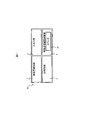
 本発明の実施例1におけるカウンタ付センサについて図面を参照しながら説明する。図1は本発明に係るセンサデバイスの一例として、カウンタ付センサS1の全体構成を示す模式図である。 The counter-equipped sensor according to the first embodiment of the present invention will be described with reference to the drawings. FIG. 1 is a schematic diagram showing the overall configuration of a counter-equipped sensor S1 as an example of a sensor device according to the present invention.
 本実施例のカウンタ付センサS1は、温度、圧力、速度、位置、加速度・角速度など道路や、ビル、橋梁、上下水道管、ガス配管などのインフラを維持・補修するために必要な物理量を測定する物理量検知部1と、センサを識別するためのID保持部2と、外部からの取得要求に連動して値が変化する情報送信履歴保管部3と、外部からの取得要求の受信、と、前記物理量検知部1からの測定値、センサのID、および情報送信履歴情報の送信とを、有線もしくは無線で行う入出力部4とで構成される。 The sensor with counter S1 of this embodiment measures physical quantities necessary for maintaining and repairing roads and infrastructure such as buildings, bridges, water and sewage pipes, and gas pipes such as temperature, pressure, speed, position, acceleration and angular velocity. A physical quantity detection unit 1 that performs identification, an ID holding unit 2 for identifying a sensor, an information transmission history storage unit 3 whose value changes in conjunction with an acquisition request from the outside, reception of an acquisition request from the outside, The measurement value from the physical quantity detection unit 1, the ID of the sensor, and the transmission of information transmission history information are configured by an input / output unit 4 that performs wired or wireless transmission.
 前記センサS1を構成する各要素について説明する。 Each element constituting the sensor S1 will be described.
 前記物理量検知部1は、既に公知であるサーミスタや熱電対方式などの原理による温度検知部と、外部の圧力変動をダイアフラムなどの変形量を静電容量の変化もしくは電気的な抵抗値の変化として検出する圧力検知部と、感湿体の水分吸収による誘電率や導電性の変化を利用する湿度検知部と、ドップラ現象を用いる速度検知部と、GPSによる測位もしくはセンサの内部に予め保管される位置情報と、可動体の変位を静電容量の変化などで検出する加速度及び角速度検知部と、特定ガスと触媒との化学反応によって発生する導電性の変化を測定するガス検知部の全部もしくは一部の組み合わせで構成され、図示しない不揮発メモリによって、これらの検知部が検知した物理量を記憶する。 The physical quantity detection unit 1 includes a temperature detection unit based on a known principle such as a thermistor or a thermocouple type, and an external pressure fluctuation as a deformation amount of a diaphragm or the like as a change in capacitance or a change in electrical resistance value. Pressure detection unit to detect, humidity detection unit that utilizes changes in dielectric constant and conductivity due to moisture absorption of moisture sensor, speed detection unit using Doppler phenomenon, GPS positioning or stored in advance in sensor All or one of position information, an acceleration and angular velocity detector that detects displacement of the movable body by a change in capacitance, and a gas detector that measures a change in conductivity caused by a chemical reaction between a specific gas and a catalyst. The physical quantities detected by these detectors are stored in a nonvolatile memory (not shown).
 次に、センサのID保持部2はセンサを識別する固有な値を記憶する不揮発メモリであり、センサの所有元ではセンサのID保持部2に記憶されている値を用いることでセンサの設置場所や、設置時期などを管理する。 Next, the sensor ID holding unit 2 is a non-volatile memory that stores a unique value for identifying the sensor, and the sensor owner uses the value stored in the sensor ID holding unit 2 to install the sensor. And manage the installation time.
 次に、情報送信履歴保管部3について説明する。本情報送信履歴保管部3には、後述する入出力部4に外部から前記物理量検知部が検知した物理量の取得要求が入力され、それに応じてセンサS1から情報を出力するたびに1ずつ数字が上昇するカウンタ30が装備されている。図2はカウンタ30の構成を示す模式図である。カウンタ30は電源が喪失された場合でもカウンタ情報を保管する不揮発性メモリ31と、臨時メモリ32、フリップフロップ回路を用いたカウンタ回路33として構成される。このような構成を持つカウンタ30に外部から取得要求が入力された場合、前記不揮発性メモリ31に保管されているカウンタ情報が臨時保管場所であるキャッシュ32にダンプされる。その後、カウンタ回路33は前記キャッシュ32に保管されている数字をひとつ上昇させ、前記キャッシュ32の値は再び前記不揮発性メモリ31に保管される。ここでは、カウンタのひとつの例としてフリップフロップ方式のカウンタ回路33及び、キャッシュ32及び、フラッシュメモリなどから構成される不揮発性メモリ31の構成を示したが、本発明の趣旨は外部の取得要求に応じてなんらかの手段でセンサ内部の値が変わりその値が保管されれば良く、図2に示しているカウンタ30の構成に限定するものではない。 Next, the information transmission history storage unit 3 will be described. In the information transmission history storage unit 3, a physical quantity acquisition request detected by the physical quantity detection unit is input from the outside to the input / output unit 4 to be described later, and each time information is output from the sensor S1, a number is incremented by one. A rising counter 30 is provided. FIG. 2 is a schematic diagram showing the configuration of the counter 30. The counter 30 is configured as a non-volatile memory 31 that stores counter information even when power is lost, a temporary memory 32, and a counter circuit 33 that uses a flip-flop circuit. When an acquisition request is input from the outside to the counter 30 having such a configuration, the counter information stored in the nonvolatile memory 31 is dumped to the cache 32 which is a temporary storage location. Thereafter, the counter circuit 33 increments the number stored in the cache 32 by one, and the value in the cache 32 is stored in the nonvolatile memory 31 again. Here, as an example of the counter, the configuration of the non-volatile memory 31 including the flip-flop type counter circuit 33, the cache 32, and the flash memory is shown, but the gist of the present invention is the external acquisition request. Accordingly, the value inside the sensor may be changed by some means and stored, and the value is not limited to the configuration of the counter 30 shown in FIG.
 ここで、図2に図示するカウンタ30は、どの要求元からの取得要求であるかを区別せず、複数の要求元から物理量の取得要求を受信した回数の合計を計数および記憶することを特徴とする。係るカウンタ30を有するセンサS1による効果については後述する。また、実施例2において説明する通り、さらに要求元を区別して、要求元のそれぞれについて取得要求を受信した回数を計数および記憶するカウンタを設けることができる。 Here, the counter 30 illustrated in FIG. 2 counts and stores the total number of times of receiving physical quantity acquisition requests from a plurality of request sources without distinguishing from which request source the acquisition request is received. And The effect of the sensor S1 having the counter 30 will be described later. Further, as described in the second embodiment, it is possible to further provide a counter that distinguishes request sources and counts and stores the number of times an acquisition request is received for each request source.
 次に入出部4について説明する。入出力部4は、外部からの取得要求を有線もしくは無線通信で受け、前記物理検知部1が測定した物理量の情報と、前記ID保持部2に記憶されている値と、共に前記カウンタ30の不揮発性メモリ31に記憶されている値と、を要求元に有線もしくは無線通信で送信するものである。ここで、前記要求元は、特許文献1の情報収集技術に示される移動体に相当する。具体的には走行中の車に装着される情報収集端末(双方向通信機能を備えたカーナビゲーションシステムなど)、もしくは、歩行中の人が携帯する携帯電話などになる。これら情報収集端末によって収集された情報は同じく従来技術で開示されている固定網を介して遠隔ホスト、などに送信される。ここで、前記遠隔ポストはそれぞれ前記センサS1からを用いて道路やパイプラインなどを管理する管理会社に相当する。勿論、本願で引用している特許文献1ないし特許文献2に開示される方法によって情報を収集しても良いが、本実施例1のカウンタ付センサS1は特許文献1及び特許文献2のような情報収集方式によって限定されるものではない。 Next, the entrance / exit part 4 will be described. The input / output unit 4 receives an acquisition request from the outside by wired or wireless communication, and both the information on the physical quantity measured by the physical detection unit 1 and the value stored in the ID holding unit 2 are stored in the counter 30. The value stored in the nonvolatile memory 31 is transmitted to the request source by wired or wireless communication. Here, the request source corresponds to a mobile body shown in the information collection technique of Patent Document 1. Specifically, it is an information collection terminal (such as a car navigation system having a two-way communication function) attached to a running car, or a mobile phone carried by a walking person. Information collected by these information collection terminals is transmitted to a remote host or the like via the fixed network disclosed in the prior art. Here, the remote posts correspond to management companies that manage roads, pipelines, and the like using the sensors S1. Of course, information may be collected by the method disclosed in Patent Document 1 or Patent Document 2 cited in the present application, but the sensor with counter S1 of the first embodiment is similar to Patent Document 1 and Patent Document 2. It is not limited by the information collection method.
 これから、本実施例に係るセンサデバイスを用いることで得られる効果について詳細を説明する。 Now, the effect obtained by using the sensor device according to the present embodiment will be described in detail.
 本実施例に係るセンサデバイスは、上述の通り、どの要求元からの取得要求であるかを区別しないカウンタを有する。このカウンタは、当該センサデバイスにとって、いわば絶対カウンタとして機能する。そのため、当該センサデバイスの性能的な寿命を設定する際にも当該カウンタに記憶された情報を用いることができる。例えば、前記センサS1は起動の繰り返しや無線送信の繰り返しなどによって、センサS1を構成するコンデンサや精密抵抗、トランジスタやOPアンプを含む各種電子回路などの電子部品の劣化と、固定部の緩みなどの実装形態の経時的な変化が発生する。これらの変化が一定水準を越えた場合、前記センサS1は性能的な寿命を迎えることになるが、その判断基準として前記カウンタ30の値を活用し、この情報に基づいて前記電池交換時と同様に前記センサS1を交換することができる。 The sensor device according to the present embodiment includes a counter that does not distinguish from which request source the acquisition request is, as described above. This counter functions as an absolute counter for the sensor device. Therefore, the information stored in the counter can also be used when setting the performance lifetime of the sensor device. For example, the sensor S1 is subject to deterioration of electronic components such as capacitors, precision resistors, various electronic circuits including transistors and OP amplifiers, and loosened fixed parts due to repeated activation and repeated wireless transmission. Changes in the mounting form over time occur. When these changes exceed a certain level, the sensor S1 reaches its performance life, but the value of the counter 30 is used as a judgment criterion, and the same as when the battery is replaced based on this information. The sensor S1 can be replaced.
 さらに、指定したエリアから環境情報を収集する場合、複数の前記センサS1からの情報が受信されることも考えられる。この場合、分析したい事象によっては、前記カウンタ30の値がより若いものもしくはある一定範囲に入っているものを選択して用いることで、より信頼性の高い事象分析にすることも可能である。 Furthermore, when environmental information is collected from a designated area, it is conceivable that information from a plurality of the sensors S1 is received. In this case, depending on the event to be analyzed, it is possible to make the event analysis more reliable by selecting and using the counter 30 whose value is smaller or within a certain range.
 また、環境埋め込みセンサはその数が増えるに従って電源工事やデータ入出力線の配線作業が大変なことから、電池駆動と無線送受信を備えたものが必要とされる。従って、前記センサS1が電池によって駆動される場合が考えられる。この場合、前記センサS1は普段はスリップモードで待機することで電池の消耗を最低限に抑える。この状態で、前記外部からの取得要求がセンサS1の入出力部4に入力された場合、センサS1は起動モードに変わり、要求元へ情報を送信することとなる。この際、一回の起動及び情報送信に要する電力消耗量は容易に計算もしくは測定することができるため、装備されている電池の容量から何回の情報送信と起動が可能かを計算することもできる。即ち、前記カウンタ30に記録された情報(カウンタ情報)を用いることで後何回分使用可能なのかを予測することができる。センサS1の維持・補修を担う管理会社としては前記カウンタ情報を現場で参照しながら管轄区域内のセンサS1もしくはそのセンサS1の電池を交換することができる。特に、前記センサS1の所有元と維持・補修を担う管理会社が異なる場合、前記センサS1の履歴や設置場所など細かい情報を教えなくても、管轄区域内の現場で無線端末から確認できるセンサの位置やカウンタ情報を元に作業を行うことができるため、前記センサS1の維持・補修にかかる費用を節減することが可能となる。図2に示すカウンタ30は、図示しないが、電池を交換してもその記憶する値が保持され、出荷時に0にセットされてから寿命を迎えるまでその記憶する値が増え続ける第1のカウンタ回路と、電池を交換した際などに外からのコマンドによって、その記憶する値が0にセットされる第2のカウンタ回路の組み合わせで構成することができる。この場合、電池交換後、第2のカウンタ回路の値を0にセットすることで、第2のカウンタ回路の値から電池の交換時期を知ることができる。 Also, as the number of environmentally-embedded sensors increases, power supply work and wiring work for data input / output lines become more difficult. Therefore, sensors equipped with battery drive and wireless transmission / reception are required. Therefore, it is conceivable that the sensor S1 is driven by a battery. In this case, the sensor S1 normally waits in the slip mode to minimize battery consumption. In this state, when an acquisition request from the outside is input to the input / output unit 4 of the sensor S1, the sensor S1 changes to the start mode and transmits information to the request source. At this time, the power consumption required for one start-up and information transmission can be easily calculated or measured, so it is possible to calculate how many times information transmission and start-up is possible from the capacity of the installed battery. it can. That is, by using the information (counter information) recorded in the counter 30, it is possible to predict how many times it can be used later. The management company responsible for maintenance / repair of the sensor S1 can replace the sensor S1 in the jurisdiction or the battery of the sensor S1 while referring to the counter information on site. In particular, when the owner of the sensor S1 and the management company responsible for maintenance / repair are different, a sensor that can be confirmed from a wireless terminal at the site in the jurisdiction without teaching detailed information such as the history and installation location of the sensor S1. Since the work can be performed based on the position and counter information, it is possible to reduce the cost for maintenance and repair of the sensor S1. Although not shown, the counter 30 shown in FIG. 2 retains its stored value even when the battery is replaced, and the stored value keeps increasing until it reaches the end of its life after being set to 0 at the time of shipment. And a second counter circuit combination in which the stored value is set to 0 by a command from the outside when the battery is replaced. In this case, the battery replacement time can be known from the value of the second counter circuit by setting the value of the second counter circuit to 0 after the battery replacement.
 本実施例に係るカウンタ付センサは、複数のインフラ管理会社が夫々重複する特定区域内に環境埋め込みセンサを設置し、互いのセンサに独立してアクセスすること(センサを共有すること)ができ、さらに、そのセンサの維持・補修を区域ごとに前記インフラ管理会社とは異なるセンサ補修会社が行う場合により発明効果を発揮することができる。詳細な運用形態などに関しては別の実施例で詳述する。 The sensor with a counter according to the present embodiment can install an environment-embedded sensor in a specific area where a plurality of infrastructure management companies overlap, and can access each other sensor independently (sharing the sensor), Furthermore, the invention effect can be exhibited when the sensor maintenance / repair is performed by a sensor repair company different from the infrastructure management company for each area. Detailed operation modes will be described in detail in another embodiment.
 以上で述べたように、環境埋め込みセンサにカウンタ機能を付与することで、高信頼な情報分析ができることと共に、センサの維持・補修にかかる費用を大幅に削減することができる。 As described above, by adding a counter function to the environment-embedded sensor, it is possible to perform highly reliable information analysis and to significantly reduce the cost for maintenance and repair of the sensor.
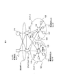
 実施例2について図3~図5を用いて説明する。なお、実施例1に記載され、本実施例に未記載の事項は特段の事情がない限り本実施例にも適用することができる。図3は、本実施例に係るカウンタ付センサの共有及び維持・補修など運用にかかる主要な構成を模式的に示す図である。 Example 2 will be described with reference to FIGS. Note that the items described in the first embodiment and not described in the present embodiment can be applied to the present embodiment unless there are special circumstances. FIG. 3 is a diagram schematically illustrating a main configuration related to operations such as sharing, maintenance, and repair of the counter-equipped sensor according to the present embodiment.
 実施例2では複数のインフラ管理会社113、114を想定し、夫々の管理会社113、114が夫々の管理下にあるインフラの環境を測定する目的で本実施例に係るセンサデバイスを環境埋め込みセンサ121、123、125、127、129および122、124、126、128、130として、エリア1とエリア2に設置していると仮定する。特に限定するわけではないが、発明の内容をイメージし易くするために、前記管理会社113が道路事業会社であり、前記管理会社114が上下水道やガス事業会社であると仮定する。一般的に上下水道のパイプやガス配管は道路の下もしくは脇に埋設される場合が多い。前記管理会社113と114は道路もしくは配管の維持・補修の情報収集を目的に環境埋め込みセンサ121~130を設置するが、精度の高い情報を得るためには数多くのセンサを設置する必要がある。しかし、夫々の会社が独立して沢山のセンサを設置し、管理することは膨大な初期設置コスト及び維持・管理コストがかかることになる。 In the second embodiment, a plurality of infrastructure management companies 113 and 114 are assumed. For the purpose of measuring the environment of the infrastructure under the management of each management company 113 and 114, the sensor device according to the present embodiment is used as the environment-embedded sensor 121. , 123, 125, 127, 129 and 122, 124, 126, 128, 130 are assumed to be installed in area 1 and area 2. Although not particularly limited, it is assumed that the management company 113 is a road business company and the management company 114 is a water and sewage and gas business company in order to make it easy to imagine the contents of the invention. In general, water and sewage pipes and gas pipes are often buried under or beside a road. The management companies 113 and 114 install the environment-embedded sensors 121 to 130 for the purpose of collecting information on maintenance / repair of roads or pipes, but in order to obtain highly accurate information, it is necessary to install many sensors. However, installing and managing a large number of sensors independently by each company requires enormous initial installation costs and maintenance / management costs.
 道路の維持・補修に必要な情報としては、温度、湿度、振動を含む環境情報が必要であり、上下水道やガス配管の維持・補修についてもガス漏れ検知と共に温度、湿度、振動と言った前記道路管理に必要な情報と共通する項目が多く含まれている。従って、前記管理会社113と114が互いのセンサ121~130を共有すれば、初期の設置コスト及びセンサの維持・管理(運用)コストを抑制しながらもより精度の高い情報を入手することができる。 Information required for road maintenance / repair requires environmental information including temperature, humidity, and vibration. For water supply / sewerage and gas pipe maintenance / repair, gas leak detection and temperature / humidity / vibration There are many items in common with information necessary for road management. Therefore, if the management companies 113 and 114 share the sensors 121 to 130, more accurate information can be obtained while suppressing initial installation costs and sensor maintenance / management (operation) costs. .
 また、環境埋め込みセンサの維持・補修についても、夫々のインフラ管理会社113、114が独自で行うのではなく、エリアを分けそのエリアごと(エリア1、エリア2)に別途の専門補修業者が行うことが効率的である。例えば、県もしくは区、市など自治単位ごとにエリアを分けることが望ましい。ここで、図3に示すエリア1とエリア2は移動体131、132と前記環境埋め込みセンサ121~130間での通信可能距離である約数m~数十mの領域を示す場合と、前記センサの補修業者141、142の管理範囲である県もしくは区、市などの領域を示す場合とを混用している。 Also, maintenance and repair of environmentally-embedded sensors are not carried out independently by the respective infrastructure management companies 113 and 114, but are performed by separate specialized repairers for each area (area 1 and area 2). Is efficient. For example, it is desirable to divide the area into autonomous units such as prefectures, wards or cities. Here, area 1 and area 2 shown in FIG. 3 indicate a region of about several meters to several tens of meters, which is a communicable distance between the mobile bodies 131 and 132 and the environment-embedded sensors 121 to 130, and the sensors The case where the area of the prefecture, ward, city, or the like, which is the management range of the repair companies 141 and 142, is used.
 本実施例では複数のインフラ管理会社(113、114)が夫々事業管轄が重複する特定区域(エリア1、エリア2)内に環境埋め込みセンサ(121~130)を設置し、互いにセンサに独立してアクセスすること(センサを共有すること)ができ、さらに、そのセンサの維持・補修を区域(エリア1、エリア2)ごとに前記インフラ管理会社113、114とは異なるセンサ補修会社141、142(図示しない)が行う場合におけるカウンタ付きセンサの役割について詳細を説明する。 In this embodiment, a plurality of infrastructure management companies (113, 114) install environmentally-embedded sensors (121-130) in specific areas (area 1, area 2) where business jurisdictions overlap, and are independent of each other. It is possible to access (sharing sensors), and maintenance / repair of the sensors is performed for each area (area 1, area 2) by sensor repair companies 141, 142 (illustrated) different from the infrastructure management companies 113, 114. Details of the role of the counter-equipped sensor in the case of (no) will be described.
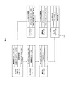
 図4は本実施例におけるカウンタ付センサS2と測定情報の流れを説明する相関図である。図3のカウンタ付センサS2の運用図、図5の情報送信履歴保管部3の構成図と合わせて詳細を説明する。まず、前記インフラ管理会社113、114は契約を結んでいるゲートウエイ134、135に要求元ID(113、114)と環境情報を測定したいエリア(エリア1、エリア2)と時間帯を送信する。ここで前記ゲートウエイ134、135は携帯電話事業社など後述する移動体131、132の位置を把握しているところに相当する。 FIG. 4 is a correlation diagram for explaining the flow of measurement information and the sensor with counter S2 in the present embodiment. Details will be described together with the operation diagram of the counter-equipped sensor S2 in FIG. 3 and the configuration diagram of the information transmission history storage unit 3 in FIG. First, the infrastructure management companies 113 and 114 transmit the request source IDs (113 and 114), the areas (area 1 and area 2) in which environmental information is to be measured, and the time zone to the gateways 134 and 135 that have contracts. Here, the gateways 134 and 135 correspond to locations where mobile units 131 and 132, which will be described later, such as a mobile phone company are grasped.
 前記ゲートウエイ134、135では前記インフラ管理会社113、114からの取得要求に基づき、指定されたエリア(エリア1、エリア2)を指定された時間帯に走行もしくは歩行中の前記移動体131,132に情報収集要求としてゲートウエイ134、135のIDもしくは前記要求元であるインフラ管理会社113、114のIDと該当移動体ID(131、132)を送信する。 In the gateways 134 and 135, based on the acquisition request from the infrastructure management companies 113 and 114, the mobile units 131 and 132 that are running or walking in the specified time zone (area 1 and area 2) in the specified time zone. As the information collection request, the ID of the gateway 134 or 135 or the ID of the infrastructure management company 113 or 114 that is the request source and the corresponding mobile body ID (131 or 132) are transmitted.
 前記移動体131、132は、環境埋め込みセンサへの取得要求として前記ゲートウエイ134、135のIDもしくは前記要求元であるインフラ管理会社113、114のIDを送信することでセンサに情報を要求する。 The mobile units 131 and 132 request information from the sensors by transmitting the IDs of the gateways 134 and 135 or the IDs of the infrastructure management companies 113 and 114 that are the request sources as an acquisition request to the environment embedded sensor.
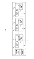
 環境埋め込みセンサ121~130は、前記移動体131、132から送信された前記ゲートウエイ134、135のIDもしくは前記要求元である前記インフラ管理会社113、114のIDが図5に示す前記センサ121~130の情報送信履歴保管部3に装備され、各要求元のそれぞれのIDを記憶する不揮発メモリであるアクセス権判断部10に登録されているものであれば、前記要求元に該当するカウンタ40~N0とトータルアクセス数を記録するカウンタT0の値をひとつ上昇させると共に、前記センサID保持部2に記憶された値、前記物理量検知部1からの環境測定値、そして前記カウンタ情報を前記移動体131、132の方に送信する。 The embedded environment sensors 121 to 130 have the IDs of the gateways 134 and 135 transmitted from the mobile units 131 and 132 or the IDs of the infrastructure management companies 113 and 114 that are the request sources as shown in FIG. If the information is registered in the access right determination unit 10 which is a non-volatile memory that stores each ID of each request source, the counters 40 to N0 corresponding to the request source are provided. The counter T0 for recording the total number of accesses is incremented by one, and the value stored in the sensor ID holding unit 2, the environmental measurement value from the physical quantity detection unit 1, and the counter information are transferred to the mobile unit 131, Send to 132.
 前記移動体131、132は、前記環境埋め込みセンサ121~130からの情報と共に必要に応じて移動体131、132に内蔵されているセンサの情報、時刻情報、そして移動体131、132のIDを前記ゲートウエイ134、135に返信する。 The mobile units 131 and 132 may include information from sensors embedded in the mobile units 131 and 132, time information, and IDs of the mobile units 131 and 132, as necessary, together with information from the environment-embedded sensors 121 to 130. Reply to the gateways 134 and 135.
 前記ゲートウエイ134、135は、前記センサ121~130からの情報と、前記移動体131、132からの情報にゲートウエイ134、135のIDを付加して前記要求元であるインフラ管理会社113、114に返信する。 The gateways 134 and 135 add the IDs of the gateways 134 and 135 to the information from the sensors 121 to 130 and the information from the mobile units 131 and 132, and send them back to the infrastructure management companies 113 and 114 that are the request sources. To do.
 このように、本実施例に係るセンサデバイスは、複数の要求元から取得要求を受信した回数の合計を計数および記憶するカウンタT0に加え、複数の要求元のそれぞれについて取得要求を受信した回数を計数および記憶する複数のカウンタ40~N0を有することを特徴とする。係る特徴により、カウンタT0に記憶する値によってセンサデバイスの寿命を測ることを可能としつつ、その上でカウンタ40~N0によって、各要求元への情報量の課金を可能とするものである。 As described above, the sensor device according to the present embodiment calculates the number of times the acquisition request is received for each of the plurality of request sources in addition to the counter T0 that counts and stores the total number of times the acquisition requests are received from the plurality of request sources. It has a plurality of counters 40 to N0 for counting and storing. With such a feature, while it is possible to measure the lifetime of the sensor device by the value stored in the counter T0, the information amount can be charged to each request source by the counters 40 to N0.
 そして、係るセンサデバイスを用い、上述した情報の流れとやり方とを用いることによって、前記インフラ管理会社113、114は必要な場所の必要な時間帯における環境情報を互いのセンサを共有しながら取得することができる。 By using such a sensor device and using the above-described information flow and method, the infrastructure management companies 113 and 114 acquire environmental information in a necessary time zone of a necessary place while sharing each other's sensors. be able to.
 さらに、詳細な仕組みは記載しないが、情報の経路が明らかであるため、必要に応じては各利害関係者間で情報料を支払うことができる。また、各インフラ管理会社113、114は互いに独立して相手のセンサにアクセスすることができるため、仮に競合の関係もしくは情報の交流がない場合でも情報を漏洩することなく、相手のセンサを使いながら環境データを収集することができる。 Furthermore, although the detailed mechanism is not described, the information route is clear, so that information fees can be paid between each interested party as necessary. In addition, since each infrastructure management company 113 and 114 can access the partner's sensor independently of each other, it is possible to use the partner's sensor without leaking information even if there is no competition relationship or information exchange. Environmental data can be collected.
 図5に示す、前記情報送信履歴保管部3のアクセス権判断部10は、図示しないが、センサデバイスの外部からの情報に基づいて、後から追加してIDとそれに対応するカウンタを登録し、または、不要なIDとそれに対応するカウンタを削除することができるものである。したがって、新規のインフラ管理業者などにセンサへのアクセス権を付与する場合には前記アクセス権判断部10に新しくIDを登録すればよい。 The access right determination unit 10 of the information transmission history storage unit 3 shown in FIG. 5 registers an ID and a counter corresponding to the ID added later based on information from outside the sensor device, although not shown. Alternatively, unnecessary IDs and corresponding counters can be deleted. Therefore, when the access right to the sensor is given to a new infrastructure management company or the like, a new ID may be registered in the access right determination unit 10.
 次は、所有元が異なる前記環境埋め込みセンサ121、123、125、127、129とセンサ122、124、126、128、130をエリア(エリア1、エリア2)ごとに第3、第4のセンサ補修管理会社が管理する場合について説明する。例えば、国道や高速道路などの広範囲にわたって設置される環境埋め込みセンサの場合、複数のインフラ管理業者113、114はエリア(エリア1、エリア2)ごとにセンサ補修業務を専門センサ補修会社141、142(図示しない)に委託する場合がある。センサ補修会社141、142は、夫々の前記インフラ管理会社113、114からセンサの交換や補修(電池交換)などに必要な情報をもらって実作業を行うことになる。 Next, the third and fourth sensors are repaired for each area (area 1, area 2) for the environment-embedded sensors 121, 123, 125, 127, and 129 and the sensors 122, 124, 126, 128, and 130 that have different owners. The case where the management company manages is explained. For example, in the case of environmentally embedded sensors installed over a wide area such as national roads and highways, a plurality of infrastructure managers 113 and 114 perform sensor repair work for each area (area 1 and area 2), specialized sensor repair companies 141 and 142 ( (Not shown). The sensor repair companies 141 and 142 receive information necessary for sensor replacement and repair (battery replacement) from the infrastructure management companies 113 and 114, and perform actual work.
 しかし、前記環境埋め込みセンサ121~130が複数の前記インフラ管理会社113、114によって共有される場合は、前記センサの使用頻度などを把握するためにはセンサのIDに対応したアクセス履歴を前記インフラ管理会社113、114の間で共有する必要があるなど煩雑な手続きが必要となる。ここで、前記カウンタ情報を用いれば、予め前記インフラ管理会社113、114から指示されている回数以上のものを交換すれば良いため、複雑な業務指示がなくてもセンサの維持・管理を行うことができる。 However, when the environment-embedded sensors 121 to 130 are shared by a plurality of the infrastructure management companies 113 and 114, in order to grasp the usage frequency of the sensor, the access history corresponding to the sensor ID is stored in the infrastructure management. Complicated procedures such as sharing between the companies 113 and 114 are required. Here, if the counter information is used, it is only necessary to exchange more than the number instructed by the infrastructure management companies 113 and 114 in advance, so that maintenance and management of the sensor can be performed even without complicated work instructions. Can do.
 なお、再び詳細は説明しないが、本実施例のカウンタ付センサS2においても、実施例1で説明したカウンタ情報を用いる場合と同様の効果が得られる。 Although details will not be described again, the counter-equipped sensor S2 of the present embodiment can achieve the same effect as the counter information described in the first embodiment.
 S1:カウンタ付きセンサ、S2:カウンタ付センサ、1:物理量検知部、2:ID保持部、3:情報送信履歴保管部、4:入出力部、10:アクセス権判断部、30:カウンタ、31:不揮発性メモリ、32:キャッシュ、33:カウンタ回路、40:カウンタ、41:不揮発性メモリ、42:キャッシュ、43:カウンタ回路、N1:不揮発性メモリ、N2:キャッシュ、N3:ウンタ回路、T0:カウンタ、T1:不揮発性メモリ、T2:キャッシュ、T3:カウンタ回路、111:固定網、113:インフラ管理会社、114:インフラ管理会社、121~130:環境埋め込みセンサ、131:移動体、132:移動体、134:ゲートウエイ、135:ゲートウエイ、141:センサ補修会社、142:センサ補修会社。 S1: Sensor with counter, S2: Sensor with counter, 1: Physical quantity detection unit, 2: ID holding unit, 3: Information transmission history storage unit, 4: Input / output unit, 10: Access right determination unit, 30: Counter, 31 : Non-volatile memory, 32: cache, 33: counter circuit, 40: counter, 41: non-volatile memory, 42: cache, 43: counter circuit, N1: non-volatile memory, N2: cache, N3: counter circuit, T0: Counter, T1: Non-volatile memory, T2: Cache, T3: Counter circuit, 111: Fixed network, 113: Infrastructure management company, 114: Infrastructure management company, 121-130: Environment embedded sensor, 131: Mobile body, 132: Movement Body: 134: Gateway, 135: Gateway, 141: Sensor repair company, 142: Sensor repair company.

Claims (5)

  1.  外部の物理量を測定する物理量検知部と、
     外部の複数の要求元から前記物理量の取得要求を受信する入出力部と、
     前記入出力部が前記複数の要求元から前記取得要求を受信した回数の合計を計数し記憶する第1カウンタと、を有し、
     前記入出力部は、前記取得要求の要求元に対し、前記物理量および前記第1カウンタが記憶する値を送信することを特徴とするセンサデバイス。
    A physical quantity detector for measuring external physical quantities;
    An input / output unit that receives the physical quantity acquisition request from a plurality of external request sources;
    A first counter that counts and stores the total number of times the input / output unit receives the acquisition request from the plurality of request sources;
    The input / output unit transmits the physical quantity and a value stored in the first counter to a request source of the acquisition request.
  2.  請求項1において、
     前記複数の要求元のそれぞれについて、前記取得要求を受信した回数を計数し記憶する複数の第2カウンタをさらに有することを特徴とするセンサデバイス。
    In claim 1,
    The sensor device further comprising a plurality of second counters for counting and storing the number of times the acquisition request is received for each of the plurality of request sources.
  3.  請求項2において、
     前記複数の要求元のそれぞれのID情報を記憶する不揮発メモリをさらに有することを特徴とするセンサデバイス。
    In claim 2,
    A sensor device further comprising: a nonvolatile memory that stores ID information of each of the plurality of request sources.
  4.  請求項3において、
     前記センサデバイスは、外部からのコマンド入力に基づいて、前記不揮発メモリにID情報を追加し、または前記不揮発メモリ記憶されたID情報を削除することを特徴とするセンサデバイス。
    In claim 3,
    The sensor device adds ID information to the nonvolatile memory or deletes the ID information stored in the nonvolatile memory based on a command input from the outside.
  5.  請求項1において、
     前記センサデバイスを駆動するための電池をさらに有し、
     前記第1カウンタは、前記複数の要求元から前記取得要求を受信した回数を計数した値のうち、前記電池を交換してもその記憶する値を保持する第1カウンタ回路と、前記電池を交換した際にその記憶する値が0にセットされる第2カウンタ回路とを有することを特徴とするセンサデバイス。
    In claim 1,
    A battery for driving the sensor device;
    The first counter replaces the battery with a first counter circuit that retains a value stored even if the battery is replaced among values obtained by counting the number of times the acquisition request has been received from the plurality of request sources. And a second counter circuit in which the stored value is set to 0.
PCT/JP2012/001909 2012-03-21 2012-03-21 Sensor device WO2013140438A1 (en)

Priority Applications (7)

Application Number Priority Date Filing Date Title
CN201280070800.XA CN104246450A (en) 2012-03-21 2012-03-21 Sensor device
EP12871876.4A EP2829849A4 (en) 2012-03-21 2012-03-21 Sensor device
JP2014505792A JP5775964B2 (en) 2012-03-21 2012-03-21 Sensor device
KR1020147023369A KR20140119139A (en) 2012-03-21 2012-03-21 Sensor device
US14/384,169 US20150036782A1 (en) 2012-03-21 2012-03-21 Sensor device
PCT/JP2012/001909 WO2013140438A1 (en) 2012-03-21 2012-03-21 Sensor device
IN7641DEN2014 IN2014DN07641A (en) 2012-03-21 2014-09-12

Applications Claiming Priority (1)

Application Number Priority Date Filing Date Title
PCT/JP2012/001909 WO2013140438A1 (en) 2012-03-21 2012-03-21 Sensor device

Publications (1)

Publication Number Publication Date
WO2013140438A1 true WO2013140438A1 (en) 2013-09-26

Family

ID=49221944

Family Applications (1)

Application Number Title Priority Date Filing Date
PCT/JP2012/001909 WO2013140438A1 (en) 2012-03-21 2012-03-21 Sensor device

Country Status (7)

Country Link
US (1) US20150036782A1 (en)
EP (1) EP2829849A4 (en)
JP (1) JP5775964B2 (en)
KR (1) KR20140119139A (en)
CN (1) CN104246450A (en)
IN (1) IN2014DN07641A (en)
WO (1) WO2013140438A1 (en)

Cited By (1)

* Cited by examiner, † Cited by third party
Publication number Priority date Publication date Assignee Title
JP2019068232A (en) * 2017-09-29 2019-04-25 サクサ株式会社 Radio communication terminal and remote meter reading system

Families Citing this family (2)

* Cited by examiner, † Cited by third party
Publication number Priority date Publication date Assignee Title
EP3734936A1 (en) 2019-04-30 2020-11-04 Orange List-based redundancy control in crowd-based iot
CN113746896B (en) * 2021-07-23 2023-07-21 深圳供电局有限公司 Data transmission method, device, system and readable storage medium

Citations (7)

* Cited by examiner, † Cited by third party
Publication number Priority date Publication date Assignee Title
WO1994029825A1 (en) * 1993-06-04 1994-12-22 M & Fc Holding Company, Inc. Duplex bi-directional multi-mode remote instrument reading and telemetry system
JPH0983661A (en) * 1995-09-19 1997-03-28 Tokyo Gas Co Ltd Communication system
US6124806A (en) * 1997-09-12 2000-09-26 Williams Wireless, Inc. Wide area remote telemetry
JP2004362267A (en) 2003-06-04 2004-12-24 Ntt Docomo Inc Mobile body, proxy device, and sensor information communication method
US6885309B1 (en) * 2000-06-01 2005-04-26 Cellnet Innovations, Inc. Meter to internet pathway
JP2006304168A (en) 2005-04-25 2006-11-02 Nec Corp Subscriber circuit testing device, subscriber circuit testing system, subscriber circuit testing method and subscriber circuit testing program
JP2008112372A (en) * 2006-10-31 2008-05-15 Toyota Motor Corp Wheel status monitoring system and wheel information transmitting device

Family Cites Families (7)

* Cited by examiner, † Cited by third party
Publication number Priority date Publication date Assignee Title
US4284849A (en) * 1979-11-14 1981-08-18 Gte Products Corporation Monitoring and signalling system
IL105476A0 (en) * 1992-08-13 1993-08-18 Utics Corp System and method for collecting data from a number of remote sensors
US5939609A (en) * 1998-03-23 1999-08-17 Conception Technology Incorporated Multi-use sensor having a controllable number of measurement cycles
US6298255B1 (en) * 1999-06-09 2001-10-02 Aspect Medical Systems, Inc. Smart electrophysiological sensor system with automatic authentication and validation and an interface for a smart electrophysiological sensor system
US7528711B2 (en) * 2005-12-19 2009-05-05 Lawrence Kates Portable monitoring unit
JP2008059312A (en) * 2006-08-31 2008-03-13 Hitachi Ltd Controller and development system therefor
JP5092020B2 (en) * 2008-11-04 2012-12-05 株式会社日立製作所 Information processing system and information processing apparatus

Patent Citations (7)

* Cited by examiner, † Cited by third party
Publication number Priority date Publication date Assignee Title
WO1994029825A1 (en) * 1993-06-04 1994-12-22 M & Fc Holding Company, Inc. Duplex bi-directional multi-mode remote instrument reading and telemetry system
JPH0983661A (en) * 1995-09-19 1997-03-28 Tokyo Gas Co Ltd Communication system
US6124806A (en) * 1997-09-12 2000-09-26 Williams Wireless, Inc. Wide area remote telemetry
US6885309B1 (en) * 2000-06-01 2005-04-26 Cellnet Innovations, Inc. Meter to internet pathway
JP2004362267A (en) 2003-06-04 2004-12-24 Ntt Docomo Inc Mobile body, proxy device, and sensor information communication method
JP2006304168A (en) 2005-04-25 2006-11-02 Nec Corp Subscriber circuit testing device, subscriber circuit testing system, subscriber circuit testing method and subscriber circuit testing program
JP2008112372A (en) * 2006-10-31 2008-05-15 Toyota Motor Corp Wheel status monitoring system and wheel information transmitting device

Non-Patent Citations (1)

* Cited by examiner, † Cited by third party
Title
See also references of EP2829849A4 *

Cited By (2)

* Cited by examiner, † Cited by third party
Publication number Priority date Publication date Assignee Title
JP2019068232A (en) * 2017-09-29 2019-04-25 サクサ株式会社 Radio communication terminal and remote meter reading system
JP7077566B2 (en) 2017-09-29 2022-05-31 サクサ株式会社 Wireless communication terminal and remote meter reading system

Also Published As

Publication number Publication date
IN2014DN07641A (en) 2015-05-15
EP2829849A4 (en) 2015-08-12
CN104246450A (en) 2014-12-24
US20150036782A1 (en) 2015-02-05
KR20140119139A (en) 2014-10-08
JP5775964B2 (en) 2015-09-09
JPWO2013140438A1 (en) 2015-08-03
EP2829849A1 (en) 2015-01-28

Similar Documents

Publication Publication Date Title
KR101037433B1 (en) Wireless communication system for managing an underground facility
US20160006576A1 (en) Information notification method
Puckett et al. Bluetooth-based travel time/speed measuring systems development.
FI128067B (en) Method and arrangement for monitoring sewer pipes
JP5775964B2 (en) Sensor device
US10012766B2 (en) Monitoring external vibration sources for data collection
WO2014184253A2 (en) Sensing device method and system
KR101022763B1 (en) Measure storing Data, Remote Meter Inspection System using the Measure and Control Method thereof
JP5004678B2 (en) POSITION ESTIMATION SYSTEM, RADIO COMMUNICATION TERMINAL, AND POSITION ESTIMATION DEVICE
CN102387350A (en) Wireless monitoring positioning system for tunnel
Zhao et al. Truck travel time reliability and prediction in a port drayage network
Jang et al. Wireless sensor technologies for automated tracking and monitoring of construction materials utilizing Zigbee networks
Ceylan et al. Development of a wireless MEMS multifunction sensor system and field demonstration of embedded sensors for monitoring concrete pavements, Volume I
JP2008197727A (en) Information recording method, input device, and communication system
Goel et al. Auto-train track fault detection system
Judd et al. Radio-frequency identification triggering system for structural health monitoring of highway bridges
US7940169B2 (en) System and method for installed base data maintenance
CN102769909A (en) Mobile terminal positioning method and mobile terminal positioning system
RU110856U1 (en) VEHICLE VOLTAGE FIXING SYSTEM VEHICLE
RU116259U1 (en) GLONASS / GPS SATELLITE TELEMATIC COMPLEX USING Inmarsat D + / GPRS COMMUNICATION CHANNELS
JP2018017586A (en) Environment measurement system and environment measurement method
Tayo et al. Design and implementation of a global positioning system based automatic vehicle location system
US20240067287A1 (en) System and method for managing shared personal mobility device
JP6994490B2 (en) Future potential evaluation device and future potential evaluation method
WO2021182476A1 (en) Travel distance estimation system

Legal Events

Date Code Title Description
121 Ep: the epo has been informed by wipo that ep was designated in this application

Ref document number: 12871876

Country of ref document: EP

Kind code of ref document: A1

ENP Entry into the national phase

Ref document number: 2014505792

Country of ref document: JP

Kind code of ref document: A

ENP Entry into the national phase

Ref document number: 20147023369

Country of ref document: KR

Kind code of ref document: A

WWE Wipo information: entry into national phase

Ref document number: 14384169

Country of ref document: US

WWE Wipo information: entry into national phase

Ref document number: 2012871876

Country of ref document: EP

NENP Non-entry into the national phase

Ref country code: DE