WO2013141119A1 - Puncture instrument and puncture device - Google Patents
Puncture instrument and puncture device Download PDFInfo
- Publication number
- WO2013141119A1 WO2013141119A1 PCT/JP2013/057061 JP2013057061W WO2013141119A1 WO 2013141119 A1 WO2013141119 A1 WO 2013141119A1 JP 2013057061 W JP2013057061 W JP 2013057061W WO 2013141119 A1 WO2013141119 A1 WO 2013141119A1
- Authority
- WO
- WIPO (PCT)
- Prior art keywords
- needle
- puncture
- extension
- puncture device
- insertion member
- Prior art date
Links
- 0 *I*1CCCC1 Chemical compound *I*1CCCC1 0.000 description 1
Images


Classifications
-
- A—HUMAN NECESSITIES
- A61—MEDICAL OR VETERINARY SCIENCE; HYGIENE
- A61B—DIAGNOSIS; SURGERY; IDENTIFICATION
- A61B17/00—Surgical instruments, devices or methods, e.g. tourniquets
- A61B17/34—Trocars; Puncturing needles
- A61B17/3417—Details of tips or shafts, e.g. grooves, expandable, bendable; Multiple coaxial sliding cannulas, e.g. for dilating
- A61B17/3421—Cannulas
-
- A—HUMAN NECESSITIES
- A61—MEDICAL OR VETERINARY SCIENCE; HYGIENE
- A61B—DIAGNOSIS; SURGERY; IDENTIFICATION
- A61B17/00—Surgical instruments, devices or methods, e.g. tourniquets
- A61B17/04—Surgical instruments, devices or methods, e.g. tourniquets for suturing wounds; Holders or packages for needles or suture materials
- A61B17/0482—Needle or suture guides
-
- A—HUMAN NECESSITIES
- A61—MEDICAL OR VETERINARY SCIENCE; HYGIENE
- A61B—DIAGNOSIS; SURGERY; IDENTIFICATION
- A61B17/00—Surgical instruments, devices or methods, e.g. tourniquets
- A61B17/04—Surgical instruments, devices or methods, e.g. tourniquets for suturing wounds; Holders or packages for needles or suture materials
- A61B17/06—Needles ; Sutures; Needle-suture combinations; Holders or packages for needles or suture materials
- A61B17/06066—Needles, e.g. needle tip configurations
- A61B17/06109—Big needles, either gripped by hand or connectable to a handle
-
- A—HUMAN NECESSITIES
- A61—MEDICAL OR VETERINARY SCIENCE; HYGIENE
- A61B—DIAGNOSIS; SURGERY; IDENTIFICATION
- A61B17/00—Surgical instruments, devices or methods, e.g. tourniquets
- A61B17/12—Surgical instruments, devices or methods, e.g. tourniquets for ligaturing or otherwise compressing tubular parts of the body, e.g. blood vessels, umbilical cord
- A61B17/12009—Implements for ligaturing other than by clamps or clips, e.g. using a loop with a slip knot
-
- A—HUMAN NECESSITIES
- A61—MEDICAL OR VETERINARY SCIENCE; HYGIENE
- A61B—DIAGNOSIS; SURGERY; IDENTIFICATION
- A61B17/00—Surgical instruments, devices or methods, e.g. tourniquets
- A61B17/34—Trocars; Puncturing needles
- A61B17/3417—Details of tips or shafts, e.g. grooves, expandable, bendable; Multiple coaxial sliding cannulas, e.g. for dilating
- A61B17/3421—Cannulas
- A61B17/3423—Access ports, e.g. toroid shape introducers for instruments or hands
-
- A—HUMAN NECESSITIES
- A61—MEDICAL OR VETERINARY SCIENCE; HYGIENE
- A61B—DIAGNOSIS; SURGERY; IDENTIFICATION
- A61B17/00—Surgical instruments, devices or methods, e.g. tourniquets
- A61B17/42—Gynaecological or obstetrical instruments or methods
-
- A—HUMAN NECESSITIES
- A61—MEDICAL OR VETERINARY SCIENCE; HYGIENE
- A61F—FILTERS IMPLANTABLE INTO BLOOD VESSELS; PROSTHESES; DEVICES PROVIDING PATENCY TO, OR PREVENTING COLLAPSING OF, TUBULAR STRUCTURES OF THE BODY, e.g. STENTS; ORTHOPAEDIC, NURSING OR CONTRACEPTIVE DEVICES; FOMENTATION; TREATMENT OR PROTECTION OF EYES OR EARS; BANDAGES, DRESSINGS OR ABSORBENT PADS; FIRST-AID KITS
- A61F2/00—Filters implantable into blood vessels; Prostheses, i.e. artificial substitutes or replacements for parts of the body; Appliances for connecting them with the body; Devices providing patency to, or preventing collapsing of, tubular structures of the body, e.g. stents
- A61F2/02—Prostheses implantable into the body
-
- A—HUMAN NECESSITIES
- A61—MEDICAL OR VETERINARY SCIENCE; HYGIENE
- A61B—DIAGNOSIS; SURGERY; IDENTIFICATION
- A61B17/00—Surgical instruments, devices or methods, e.g. tourniquets
- A61B17/34—Trocars; Puncturing needles
- A61B17/3468—Trocars; Puncturing needles for implanting or removing devices, e.g. prostheses, implants, seeds, wires
-
- A—HUMAN NECESSITIES
- A61—MEDICAL OR VETERINARY SCIENCE; HYGIENE
- A61B—DIAGNOSIS; SURGERY; IDENTIFICATION
- A61B17/00—Surgical instruments, devices or methods, e.g. tourniquets
- A61B2017/00743—Type of operation; Specification of treatment sites
- A61B2017/00805—Treatment of female stress urinary incontinence
-
- A—HUMAN NECESSITIES
- A61—MEDICAL OR VETERINARY SCIENCE; HYGIENE
- A61B—DIAGNOSIS; SURGERY; IDENTIFICATION
- A61B17/00—Surgical instruments, devices or methods, e.g. tourniquets
- A61B2017/00831—Material properties
-
- A—HUMAN NECESSITIES
- A61—MEDICAL OR VETERINARY SCIENCE; HYGIENE
- A61B—DIAGNOSIS; SURGERY; IDENTIFICATION
- A61B17/00—Surgical instruments, devices or methods, e.g. tourniquets
- A61B17/04—Surgical instruments, devices or methods, e.g. tourniquets for suturing wounds; Holders or packages for needles or suture materials
- A61B17/06—Needles ; Sutures; Needle-suture combinations; Holders or packages for needles or suture materials
- A61B17/06004—Means for attaching suture to needle
- A61B2017/06042—Means for attaching suture to needle located close to needle tip
-
- A—HUMAN NECESSITIES
- A61—MEDICAL OR VETERINARY SCIENCE; HYGIENE
- A61B—DIAGNOSIS; SURGERY; IDENTIFICATION
- A61B17/00—Surgical instruments, devices or methods, e.g. tourniquets
- A61B17/12—Surgical instruments, devices or methods, e.g. tourniquets for ligaturing or otherwise compressing tubular parts of the body, e.g. blood vessels, umbilical cord
- A61B2017/12004—Surgical instruments, devices or methods, e.g. tourniquets for ligaturing or otherwise compressing tubular parts of the body, e.g. blood vessels, umbilical cord for haemostasis, for prevention of bleeding
-
- A—HUMAN NECESSITIES
- A61—MEDICAL OR VETERINARY SCIENCE; HYGIENE
- A61B—DIAGNOSIS; SURGERY; IDENTIFICATION
- A61B17/00—Surgical instruments, devices or methods, e.g. tourniquets
- A61B17/34—Trocars; Puncturing needles
- A61B17/3417—Details of tips or shafts, e.g. grooves, expandable, bendable; Multiple coaxial sliding cannulas, e.g. for dilating
- A61B17/3421—Cannulas
- A61B2017/3443—Cannulas with means for adjusting the length of a cannula
-
- A—HUMAN NECESSITIES
- A61—MEDICAL OR VETERINARY SCIENCE; HYGIENE
- A61B—DIAGNOSIS; SURGERY; IDENTIFICATION
- A61B17/00—Surgical instruments, devices or methods, e.g. tourniquets
- A61B17/34—Trocars; Puncturing needles
- A61B17/3417—Details of tips or shafts, e.g. grooves, expandable, bendable; Multiple coaxial sliding cannulas, e.g. for dilating
- A61B2017/3454—Details of tips
-
- A—HUMAN NECESSITIES
- A61—MEDICAL OR VETERINARY SCIENCE; HYGIENE
- A61B—DIAGNOSIS; SURGERY; IDENTIFICATION
- A61B90/00—Instruments, implements or accessories specially adapted for surgery or diagnosis and not covered by any of the groups A61B1/00 - A61B50/00, e.g. for luxation treatment or for protecting wound edges
- A61B90/08—Accessories or related features not otherwise provided for
- A61B2090/0801—Prevention of accidental cutting or pricking
-
- A—HUMAN NECESSITIES
- A61—MEDICAL OR VETERINARY SCIENCE; HYGIENE
- A61F—FILTERS IMPLANTABLE INTO BLOOD VESSELS; PROSTHESES; DEVICES PROVIDING PATENCY TO, OR PREVENTING COLLAPSING OF, TUBULAR STRUCTURES OF THE BODY, e.g. STENTS; ORTHOPAEDIC, NURSING OR CONTRACEPTIVE DEVICES; FOMENTATION; TREATMENT OR PROTECTION OF EYES OR EARS; BANDAGES, DRESSINGS OR ABSORBENT PADS; FIRST-AID KITS
- A61F2/00—Filters implantable into blood vessels; Prostheses, i.e. artificial substitutes or replacements for parts of the body; Appliances for connecting them with the body; Devices providing patency to, or preventing collapsing of, tubular structures of the body, e.g. stents
- A61F2/0004—Closure means for urethra or rectum, i.e. anti-incontinence devices or support slings against pelvic prolapse
- A61F2/0031—Closure means for urethra or rectum, i.e. anti-incontinence devices or support slings against pelvic prolapse for constricting the lumen; Support slings for the urethra
- A61F2/0036—Closure means for urethra or rectum, i.e. anti-incontinence devices or support slings against pelvic prolapse for constricting the lumen; Support slings for the urethra implantable
- A61F2/0045—Support slings
Definitions
- the present invention relates to a puncture device and a puncture device.
- Urinary incontinence particularly stress urinary incontinence, urine leakage occurs due to abdominal pressure applied during normal exercise, laughing, coughing, sneezing, etc.
- the cause of this is, for example, that the pelvic floor muscle, which is a muscle that supports the urethra, is loosened due to childbirth and the like.
- Surgical therapy is effective for the treatment of urinary incontinence.
- a band-like tissue-supporting indwelling material called a “sling”
- the sling is placed in the body, and the sling supports the urethra (for example, Patent Document 1).
- the operator incises the vagina with a scalpel, peels off the space between the urethra and the vagina, and uses the puncture needle or the like to connect the peeled portion and the outside through a closed hole. In such a state, the sling is left in the body.
- vagina is incised, there is a risk that a sling may be exposed in the vagina from the wound generated by the incision, and there may be complications such as infection from the wound.
- vagina since the vagina is incised, there is a disadvantage that the invasion is large and the burden on the patient is large.
- the urethra or the like may be damaged during the procedure by the surgeon, and the surgeon himself may also damage the fingertip.
- An object of the present invention is that a living tissue supporting indwelling object can be easily embedded in a living body, the burden on the patient is low, the safety of the patient is high, and the safety of the operator is high. It is an object of the present invention to provide a puncture device and a puncture device that can accommodate a patient having a relatively large thickness.
- the present invention relates to a puncture needle having a needle body that punctures a living tissue, and an extension needle that is provided so as to be movable relative to the needle body along the longitudinal direction of the needle body and that pierces the living tissue.
- a puncture device comprising: an extension means for extending the puncture needle by moving the extension needle with respect to the needle body in a distal direction of the needle body.
- the needle body has a hollow portion
- the extension needle is preferably inserted in the hollow portion of the needle body so as to be movable along the longitudinal direction of the needle body.
- the needle body has an opening communicating with the hollow portion at the tip thereof
- the extension needle has a needle tip capable of puncturing a living tissue at a tip thereof, and the needle tip is positioned on the needle body when the extension needle is located on the most proximal side with respect to the needle body. It is preferable to protrude from the opening.
- the elongating means has an elongated shape, is inserted into a hollow portion of the needle body, and moves the extension needle by pressing the extension needle.
- the extension needle has a hollow portion, It is preferable that the extension means is inserted into a hollow portion of the extension needle and moves the extension needle by pressing a tip portion of the extension needle.
- the puncture device of the present invention preferably has an elongated living tissue support indwelling that is embedded in a living body and supports the living tissue.
- the extension means has an engaging portion that engages with the living tissue supporting indwelling material at a distal end portion thereof.
- the extension needle is detachable from the needle body.
- each of the needle body and the extension needle has a flat shape when viewed in the longitudinal direction.
- the needle body and the extension needle each have a portion that is curved along the longitudinal direction thereof.
- the needle body and the extension needle are respectively installed rotatably.
- the present invention provides a puncture device of the present invention, A longitudinal urethral insertion member inserted into the urethra;
- a puncture apparatus comprising: a regulating unit that regulates a positional relationship with the urethral insertion member.
- the puncture device of the present invention has a longitudinal vaginal insertion member inserted into the vagina,
- the restricting means determines the positional relationship between the puncture needle and the vaginal insertion member so that the needle tip of the extension needle does not collide with the vaginal insertion member when the puncture needle rotates to puncture living tissue. It is preferable to regulate.
- the puncture device has a shaft portion that forms the rotation axis of the rotation
- the restricting means preferably includes a support member that rotatably supports the shaft portion and supports the urethral insertion member and the vaginal insertion member.
- the living tissue supporting indwelling can be easily embedded in the living body, and when the living tissue supporting indwelling is embedded, the burden on the patient is low, the safety of the patient is high, and In addition, the safety of the operator is high, and it is possible to cope with a patient having a relatively thick subcutaneous tissue.
- the tip of the extension needle is farther from the center of the portion where the extension needle is curved in the arc shape than the urethra insertion member.
- a restricting means for restricting the positional relationship between the puncture needle and the urethral insertion member is provided so as to pass through the side, for example, when the puncture device is used for treatment of female urinary incontinence, the urethra insertion of the puncture device The member is inserted into the urethra, the puncture needle is rotated, and the living body is punctured by the puncture needle.
- the living body can be punctured avoiding the urethra, and the puncture needle punctures the urethra. Can be prevented. Moreover, it is possible to prevent the operator's fingertip from being punctured with the puncture needle.
- the puncture needle can be extended, it is possible to cope with a patient having a relatively thick subcutaneous tissue.
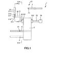
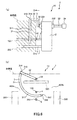
- FIG. 1 is a side view showing a first embodiment of the puncture apparatus of the present invention.
- FIG. 2 is a cross-sectional view taken along line AA in FIG. 3 is a cross-sectional view of the puncture needle of the puncture device shown in FIG. 1 taken along line BB in FIG. 4 is a cross-sectional view showing a state in which a balloon catheter is inserted into the urethral insertion member of the puncture device shown in FIG.
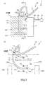
- FIG. 5 is a diagram for explaining an operation procedure of the puncture apparatus shown in FIG.
- FIG. 6 is a diagram for explaining an operation procedure of the puncture apparatus shown in FIG.
- FIG. 7 is a diagram for explaining an operation procedure of the puncture device shown in FIG. 1.
- FIG. 8 is a diagram for explaining an operation procedure of the puncture device shown in FIG. 1.
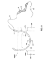
- FIG. 9 is a cross-sectional view for explaining an operation procedure of the puncture device shown in FIG.
- FIG. 10 is a cross-sectional view for explaining an operation procedure of the puncture apparatus shown in FIG.
- FIG. 11 is a cross-sectional view for explaining an operation procedure of the puncture apparatus shown in FIG.
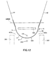
- FIG. 12 is a cross-sectional view for explaining an operation procedure of the puncture device shown in FIG.
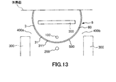
- FIG. 13 is a cross-sectional view for explaining an operation procedure of the puncture device shown in FIG.
- FIG. 14 is a side view showing a second embodiment of the puncture apparatus of the present invention.
- FIG. 15 is a cross-sectional view taken along the line GG in FIG.
- FIG. 16 is a cross-sectional view showing a third embodiment of the puncture device of the present invention.
- FIG. 1 is a side view showing a first embodiment of the puncture device of the present invention
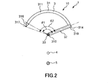
- FIG. 2 is a cross-sectional view taken along line AA in FIG. 1
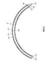
- FIG. 3 is a diagram of the puncture needle of the puncture device shown in FIG. 1 is a cross-sectional view taken along line BB in FIG. 1
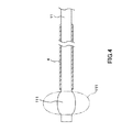
- FIG. 4 is a cross-sectional view showing a state where a balloon catheter is inserted into the urethral insertion member of the puncture device shown in FIG. 5 to 8 are diagrams for explaining the operation procedure of the puncture device shown in FIG. 1
- FIGS. 9 to 13 are cross-sectional views for explaining the operation procedure of the puncture device shown in FIG.
- FIG. 5 (a), 6 (a), 7 (a), and 8 (a) are side views, and FIG. 5 (b) is a CC line in FIG. 5 (a).
- 6B is a cross-sectional view taken along the line DD in FIG. 6A
- FIG. 7B is a cross-sectional view taken along the line EE in FIG. 7A.
- FIG. 8B is a cross-sectional view taken along line FF in FIG. 9 to 13 correspond to the cross-sectional view taken along the line CC in FIG. 5A.
- FIGS. 5 (b), 6 (b), 7 (b), 8 (b), and 9 to 13 oblique lines in the living body are omitted for easy viewing.
- FIG. 6 b
- FIG. 7 b
- FIG. 8 b
- FIG. 9 to FIG. 13, in order to facilitate understanding, a puncture member that is originally hidden behind a living body and cannot be seen.
- a pusher, a living tissue supporting indwelling object, and the like are illustrated.
- FIG. 1 the left side in FIG. 1, FIG. 4 (a), FIG. 5 (a), FIG. 6 (a), FIG. 7 (a), and FIG. Give an explanation.
- the puncture apparatus 1 shown in these drawings is an apparatus used when a living tissue supporting indwelling material for treatment of urinary incontinence of a woman, that is, treatment of urinary incontinence, is embedded in a living body.
- An indwelling device for supporting living tissue is an implantable device for the treatment of female urinary incontinence, that is, a device that is embedded in a living body and supports the urethra (living tissue), for example, the urethra tries to move toward the vagina wall side. In this case, the urethra is supported by being tension-free or being pulled away from the vagina wall.
- a living tissue supporting indwelling object for example, a flexible long object can be used.
- the biological tissue supporting indwelling object 8 includes a main body 80 having a band shape, a thread 81 fixed to one end of the main body 80, and the other of the main body 80. And a thread 82 fixed to the end of the thread.
- This living tissue supporting indwelling object 8 is called a “sling”.
- the main body 80 has a net-like shape, and can be constituted by, for example, a braided body in which a linear body is crossed and knitted into a net-like (lattice-like) shape, that is, a net-like braided body.
- the linear body include a circular cross-sectional shape, a flat cross-sectional shape, that is, a belt-like (ribbon-like) shape.
- constituent material of the main body portion 80 of the biological tissue supporting indwelling article 8 is not particularly limited, and for example, various resin materials having biocompatibility can be used.
- the constituent materials of the threads 81 and 82 are not particularly limited, and various resin materials, fibers, and the like can be used, for example. Needless to say, the main body 80 is not limited to the net-like body.
- the puncture device 1 includes a puncture needle 31 that punctures a biological tissue, a shaft portion 33, a puncture member 3 having a connection portion 32 that connects the puncture needle 31 and the shaft portion 33, and a biological tissue.
- a puncture device 10 including a supporting indwelling object 8 is provided.
- the connecting portion 32 connects the shaft portion 33 and a needle body 311 to be described later of the puncture needle 31.
- the puncture device 1 further includes a longitudinal urethral insertion member 4 inserted into the urethra, a longitudinal vagina insertion member 5 inserted into the vagina, the puncture member 3, the urethral insertion member 4, and the vagina. And a support member (regulating means) 2 that supports the insertion member 5.
- the urethral insertion member 4 is fixed to the support member 2 in this embodiment.
- the urethral insertion member 4 may be detachably installed on the support member 2.
- the urethral insertion member 4 has a straight tube shape, and the opening at the base end thereof is open at the base end face of the support member 2.
- Various long medical instruments for example, a balloon catheter 11 provided with a balloon 111 that can be expanded and contracted at its distal end as shown in FIG. 4 can be inserted into the urethral insertion member 4. .
- the state in which the balloon 111 is deflated is indicated by a solid line
- the state in which the balloon 111 is expanded is indicated by a two-dot chain line.
- the balloon 111 of the balloon catheter 11 functions as a restricting portion that restricts the position in the axial direction (longitudinal direction) of the urethral insertion member 4 in the urethra. That is, when the puncture apparatus 1 is used, the balloon 111 is inserted into the patient's bladder, the axial positional relationship between the balloon catheter 11 and the urethral insertion member 4 is fixed, and the balloon 111 is in an expanded state. By hooking on the bladder neck, the position of the urethral insertion member 4 with respect to the bladder and urethra is fixed.
- a balloon expansion device such as a syringe (not shown) is connected to a port (not shown) that communicates with a lumen (not shown) that communicates with the balloon 111 of the balloon catheter 11, and the working fluid supplied from the balloon expansion device is supplied to the lumen. Then, the balloon 111 is fed into the inside of the balloon 111, or the working fluid is extracted to expand and contract the balloon 111.
- a liquid such as physiological saline, a gas, or the like can be used.
- the balloon catheter 11 can be used for urination of the patient when the puncture device 1 is used.
- a marker 41 is provided on the outer peripheral portion of the urethral insertion member 4.
- the marker 41 is arranged so that the marker 41 is positioned at the urethral opening when the urethral insertion member 4 is inserted into the urethra and the distal end of the urethra insertion member 4 is positioned immediately before the bladder.
- the vaginal insertion member 5 is fixed to the support member 2 in this embodiment.
- the vaginal insertion member 5 may be detachably installed on the support member 2.
- the vaginal insertion member 5 has a straight bar shape.
- the tip of the vagina insertion member 5 is rounded. Thereby, the vagina insertion member 5 can be smoothly inserted into the vagina.
- vaginal insertion member 5 is disposed below the urethra insertion member 4 at a predetermined distance from the urethra insertion member 4 so that the axis thereof and the axis of the urethra insertion member 4 are parallel to each other.
- the constituent materials of the vaginal insertion member 5, the urethral insertion member 4, and the support member 2 are not particularly limited, and various resin materials can be used, for example.
- the shaft member 33 of the puncture member 3 is rotatably installed on the support member 2. Further, the shaft portion 33 is disposed above the urethra insertion member 4 at a predetermined distance from the urethra insertion member 4 so that the axis thereof and the axis of the urethra insertion member 4 are parallel to each other. Further, when viewed from the axial direction of the shaft portion 33, the shaft portion 33, the urethral insertion member 4, and the vaginal insertion member 5 are arranged on a straight line.
- the shaft portion 33 penetrates the support member 2 in the left-right direction in FIG.
- a flange 331 and a flange 332 are respectively formed on the distal end side and the proximal end side of the shaft portion 33 via the support member 2, and the shaft portion 33 with respect to the support member 2 is formed by the flanges 331 and 332. Is prevented from moving in the axial direction.
- the puncture needle 31 has a needle body 311 for puncturing a living tissue, and an extension needle 316 provided so as to be movable relative to the needle body 311 along the longitudinal direction of the needle body 311. is doing. That is, the puncture needle 31 is extended when the extension needle 316 moves in the distal direction of the needle body 311 with respect to the needle body 311.
- the puncture device 10 moves the extension needle 316 with respect to the needle body 311 in the distal direction of the needle body 311, and presses the extension needle 316 as an extension means for extending the puncture needle 31, so that the distal end of the needle body 311.
- the pusher 7 is moved in the direction.
- the needle body 311 has a hollow portion 312 extending from the proximal end to the distal end, and has a tubular shape. That is, the needle body 311 has an opening 313 communicating with the hollow portion 312 at the distal end and an opening 314 communicating with the hollow portion 312 at the proximal end.
- the extension needle 316 is inserted into the hollow portion 312 of the needle body 311 so as to be movable along the longitudinal direction of the needle body 311. Further, the extension needle 316 can be detached from the opening 313 of the needle body 311.
- extension needle 316 has a sharp needle tip 317 at its tip, and the needle tip 317 protrudes from the opening 313 of the needle body 311 in the tip direction.
- the state shown in FIG. 3 of the puncture needle 31 is the initial state, and in this initial state, the extension needle 316 is located on the most proximal side with respect to the needle body 311.
- the needle tip 317 of the extension needle 316 protrudes from the opening 313 of the needle body 311 in the distal direction. That is, the needle tip 317 of the extension needle 316 always protrudes from the opening 313 of the needle body 311 in the distal direction.
- the extension needle 316 has a hollow portion 318 extending from the proximal end to the distal end portion, and has an opening 319 communicating with the hollow portion 318 at the proximal end.
- the opening 319 forms an entrance of the pusher 7 when the pusher 7 is inserted into the hollow portion 318. Note that the tip of the extension needle 316 is closed.
- the distal end of the needle body 311 contacts the outer peripheral portion of the distal end portion of the extension needle 316 in the initial state shown in FIG. 3 in which the extension needle 316 is inserted into the hollow portion 312 of the needle body 311 over the entire circumference.
- a contact portion 315 is formed. Accordingly, when the shaft portion 33 is rotated clockwise in FIG. 3 and the needle body 311 is moved (rotated) clockwise in FIG. 3, the extension needle 316 is integrated with the needle body 311. Move clockwise in 3.
- the pusher 7 has a long shape and is inserted into the hollow portion 312 of the needle body 311, that is, the hollow portion 318 of the extension needle 316 from the opening 319, and presses the distal end portion of the extension needle 316 to push the extension needle 316. It is moved in the tip direction.
- the cross-sectional shape of the pusher 7 corresponds to the cross-sectional shape of the hollow portion 318 of the extension needle 316.
- the pusher 7 has flexibility and can correspond to the shapes of the needle body 311 and the extension needle 316. Since the distal end portion of the extension needle 316 is closed, the distal end portion of the pusher 7 can contact the distal end portion of the extension needle 316 and press the distal end portion of the extension needle 316.
- the pusher 7 has a through hole 71 as an engaging portion that engages with the living tissue supporting indwelling object 8 at the tip thereof.
- the through hole 71 penetrates the pusher 7 in a direction perpendicular to the longitudinal direction of the pusher 7. Either one of the thread 81 and the thread 82 of the living tissue supporting indwelling article 8 is inserted into the through hole 71, engaged, and held so as to be removable (see FIG. 11).
- the pusher 7 When the puncture needle 31 is extended, the pusher 7 is inserted into the hollow portion 318 from the opening 319 of the extension needle 316, and the extension needle 316 is pressed by the pusher 7 and moved in the distal direction. At this time, since the extension needle 316 is positioned on the inner peripheral side of the needle body 311, the contact area between the extension needle 316 and the living tissue can be made relatively small, and the puncture needle 31 can be easily and smoothly extended. In addition, the burden on the patient can be reduced.
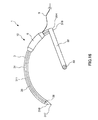
- the puncture needle 31, that is, the needle main body 311 and the extension needle 316 are curved in an arc shape around the shaft portion 33 along the longitudinal direction thereof.
- the axis of the puncture needle 31 and the axis of the shaft portion 33 are orthogonal to each other.
- the needle tip 317 of the extension needle 316 moves along the arc in a plane perpendicular to the axis of the shaft portion 33, that is, in a plane having the axis as a normal line. To do.
- the needle tip 317 of the extension needle 316 faces in the counterclockwise direction in FIG. 2, but is not limited to this, and may point in the clockwise direction in FIG.
- the puncture needle 31 is disposed on the proximal side of the distal end portion of the urethra insertion member 4 in the axial direction of the urethra insertion member 4.
- the puncture needle 31 may be disposed at the same position as the distal end portion of the urethral insertion member 4 in the axial direction of the urethral insertion member 4, and is disposed more distal than the distal end portion of the urethral insertion member 4. It may be.
- the support member 2 has the needle tip 317 of the extension needle 316 connected to the urethra insertion member 4 or its extension line. More than the center 310 of the puncture needle 31 (extension needle 316), that is, the puncture member 3 (puncture needle 31) and the urethral insertion member 4 so as to pass through the urethra insertion member 4 or below the extension line thereof.
- the positional relationship is regulated.
- the center 310 of the puncture needle 31 is the center of the arc of the puncture needle 31. That is, it is the rotation center of the puncture needle 31 (puncture member 3).
- the support member 2 has the needle tip 317 of the extension needle 316 collide with the vaginal insertion member 5 and its extension line.
- the positional relationship between the puncture member 3 (puncture needle 31) and the vaginal insertion member 5 is regulated so as not to cause a problem.
- the support member 2 is configured such that when the shaft portion 33, that is, the puncture member 3 is rotated and the puncture needle 31 punctures a living tissue, the needle tip 317 of the extension needle 316 is connected to the urethra insertion member 4 or its
- the positional relationship among the puncture member 3 (puncture needle 31), the urethral insertion member 4, and the vaginal insertion member 5 is regulated so as to pass between the extension line and the vaginal insertion member 5 or its extension line.
- the living tissue can be punctured by avoiding the urethra and the vagina wall by the puncture needle 31, and the puncture needle 31 can be prevented from puncturing the urethra and the vagina wall. And since the puncture needle 31 expand
- the surgeon himself can be prevented from puncturing the fingertip with the puncture needle 31, which is safe.
- the center angle ⁇ 1 of the arc of the needle body 311, the center angle ⁇ 2 of the arc of the extension needle 316, and the center angle ⁇ 3 of the arc of the puncture needle 31 in the state where the puncture needle 31 is most extended are respectively limited.
- the puncture needle 31 enters the body from one body surface of the patient and passes below the urethra. Thus, it is set so that it can protrude from the other body surface to the outside of the body.
- ⁇ 3- ⁇ 1 is ⁇ 2.
- the center angle ⁇ 1 of the arc of the needle body 311 is preferably 95 to 180 °, more preferably 120 to 150 °.
- the central angle ⁇ 3 of the arc of the puncture needle 31 in a state where the puncture needle 31 is most extended is preferably 190 to 270 °, and more preferably 200 to 250 °.
- the puncture needle 31 when puncturing a living tissue with the puncture needle 31, the puncture needle 31 surely enters the body from one body surface of the patient, passes below the urethra, and projects out of the body from the other body surface. be able to.
- a grip portion 34 is provided at the proximal end portion of the shaft portion 33 as an operation portion for rotating the puncture member 3.
- the shape of the grip portion 34 is a rectangular parallelepiped. When the puncture member 3 is rotated, the grip portion 34 is gripped with fingers and rotated in a predetermined direction. Needless to say, the shape of the grip portion 34 is not limited to this.
- the connecting portion 32 has an L shape in the present embodiment.
- the distal end portion of the connecting portion 32 is fixed to the proximal end portion of the needle body 311, and the proximal end portion of the connecting portion 32 is fixed to the distal end portion of the shaft portion 33.
- the puncture needle 31 and the shaft portion 33 can be separated from each other by a predetermined distance in the axial direction of the shaft portion 33.
- connection portion 32 and the needle body 311 may be integrated, the connecting portion 32 and the shaft portion 33 may be integrated, or the needle body 311, the connecting portion 32 and the shaft portion. 33 may be integrated.
- shape of the connection part 32 is not limited to this.
- the constituent material of the puncture member 3 is not particularly limited, and various metal materials such as stainless steel, aluminum or aluminum alloy, titanium or titanium alloy can be used.
- the puncture device 1 is attached to a patient. That is, the urethral insertion member 4 of the puncture device 1 is inserted into the patient's urethra 100 and the vagina insertion member 5 is inserted into the patient's vagina 200. At this time, the marker 41 is positioned in front of the urethral orifice or the urethral orifice. Thereby, the front-end
- the needle tip 317 of the extension needle of the puncture needle 31 moves counterclockwise in FIG. 6B along the arc, and the left buttock of the patient in FIG.
- the body surface is punctured, enters the body, passes through the closing hole 400a of the pelvis 300, passes below the urethra 100, that is, between the urethra 100 and the vagina 200, and passes through the closing hole 400b of the pelvis 300.
- the pusher 7 is inserted into the hollow portion 318 from the opening 319 of the extension needle 316, and the distal end portion of the extension needle 316 is pressed in the distal direction by the pusher 7, The extension needle 316 is moved in the distal direction.
- the needle tip 317 of the extension needle moves along the arc in the counterclockwise direction in FIG. 8 (b), and moves from the body surface of the right buttocks in FIG. 8 (b) to the outside of the body. Protruding.
- the tip of the pusher 7 also protrudes from the body surface to the outside together with the extension needle 316.
- the patient is allowed to pass through the obturator hole 400a, between the urethra 100 and the vagina 200, and the obturator hole 400b from the body surface of the left buttocks in FIG.
- a through-hole 500 reaching the body surface of the right buttock or its vicinity in FIG. 6B is formed.
- a living tissue supporting indwelling object 8 is embedded in the through hole 500.
- the extension needle 316 is pulled in the distal direction to be detached from the opening 313 of the needle body 311.
- the distal end portion of the needle body 311 moves clockwise in FIG. 10 along the arc, passes below the urethra 100, that is, between the urethra 100 and the vagina 200, and passes through the closing hole 400a of the pelvis 300. Passes out of the body surface of the left buttocks or its vicinity in FIG. That is, the needle body 311 is removed from the body.
- the end portion of the thread 81 engages with the through hole 71 of the pusher 7 and is removably held at the tip portion of the pusher 7.
- puncture device 1 is removed from the patient. That is, the urethral insertion member 4 is extracted from the urethra 100 and the vagina insertion member 5 is extracted from the patient's vagina 200.
- the left end of the pusher 7 in FIG. 11 is gripped, and the pusher 7 is pulled and removed from the patient.
- the end portion of the thread 81 of the living tissue supporting indwelling object 8 protrudes from the body surface to the outside through the through-hole 500 formed in the patient.
- the threads 81 and 82 are each pulled with a predetermined force to adjust the position of the body portion 80 of the biological tissue support indwelling 8 with respect to the urethra 100, and Unnecessary parts are excised, predetermined treatment is performed, and the procedure is terminated.
- the puncture device 1 when the indwelling object 8 for supporting biological tissue is placed, it can be handled only by a minimally invasive technique such as puncture of the puncture needle 31, and an incision with a large invasiveness. Therefore, the burden on the patient is small and the safety of the patient is high.
- the puncture needle 31 can puncture the living body while avoiding the urethra and the vagina wall, and the puncture needle 31 can prevent the urethra and the vagina wall from being punctured. is there. And since the puncture needle 31 expand
- the puncture hole formed in the patient by the puncture needle 31 is a through-hole.
- the present invention is not limited to this, and the puncture hole may not penetrate.
- the urethral insertion member is not limited to a tubular member, and may be, for example, a solid member, or a hollow member that is hollow and has one or both of its distal end portion and proximal end portion closed. Good.
- an expandable / deflated balloon may be provided at the distal end of the urethra insertion member as a restriction portion for restricting the axial position of the urethra insertion member in the urethra.
- FIG. 14 is a side view showing a second embodiment of the puncture apparatus of the present invention
- FIG. 15 is a cross-sectional view taken along the line GG in FIG. In the following description, the left side in FIG.
- the puncture needle 31 that is, the needle body 311 and the extension needle 316, each have a flat shape when viewed in the longitudinal direction. Yes.
- the cross-sectional shapes of the needle main body 311 and the extension needle 316 correspond to the cross-sectional shapes of the main body portion 80 of the biological tissue supporting indwelling article 8, respectively.
- the through-hole 500 of the shape corresponding to the main-body part 80 of the biological tissue support indwelling thing 8 can be formed with respect to a patient, and the biological tissue support indwelling thing 8 can be embedded more easily and appropriately. it can. And according to this puncture apparatus 1, the effect similar to 1st Embodiment mentioned above is also acquired.
- FIG. 16 is a cross-sectional view showing a third embodiment of the puncture device of the present invention.
- FIG. 16 corresponds to FIG. 2 in the first embodiment, and
- FIG. 16 shows a portion of the puncture member.
- the puncture device 1 includes a tubular sheath 6 that is movably installed along the longitudinal direction of the puncture needle 31 of the puncture member 3, and punctures by pressing the sheath 6.
- the pusher 9 is moved in the direction of the distal end of the needle 31.
- the length of the sheath 6 is set shorter than the needle body 311.
- the sheath 6 has a shape corresponding to a part of the needle body 311 and is curved in an arc shape.
- the pusher 9 the same thing as the pusher 7 in 1st Embodiment can be used.
- One end of the pusher 9 is fixed to the proximal end of the sheath 6.
- the pusher 9 is provided with a scale (not shown) indicating the position of the sheath 6 with respect to the puncture needle 31.
- grooves 35 and 36 are formed on the outer peripheral surfaces of the needle body 311 and the extension needle 316 along the longitudinal direction, respectively.
- the groove 35 and the groove 36 are formed at the same position as each other, and communicate with each other when the extension needle 316 is moved in the distal direction of the needle body 311 with respect to the needle body 311.
- channels 35 and 36 have respectively comprised linear form in this embodiment, it is not limited to this, For example, spiral shape etc. are mentioned, for example.
- this puncture device 1 for example, when a patient's blood vessel or the like is punctured by the needle tip 317 of the extension needle of the puncture needle 31 and bleeding, the blood flows in the proximal direction in the grooves 35 and 36. That is, blood backflushing occurs. Thereby, it can be grasped that bleeding is occurring in the patient's living body, that is, the patient's blood vessel or the like has been punctured with the needle tip 317 of the extension needle.
- the sheath 6 is pressed in the distal direction by the pusher 9, the sheath 6 is moved in the distal direction along the puncture needle 31, and the sheath 6 is disposed at the site where the patient is bleeding. Thereby, hemostasis can be performed. And according to this puncture apparatus 1, the effect similar to 1st Embodiment mentioned above is also acquired.
- the sheath 6 may have a lumen through which a liquid such as a chemical flows, for example.
- a liquid such as a chemical flows, for example.
- One or more side holes communicating with the lumen may be formed on the side surface of the sheath 6.
- the means for hemostasis is not limited to the sheath 6, but other than this, for example, an expandable / deflated balloon may be provided on the sheath 6.
- the present invention may be a combination of any two or more configurations of the above embodiments.
- the extension needle in the puncture needle, is inserted into the hollow portion of the needle body.
- the needle body is inserted into the hollow portion of the extension needle. Also good. That is, the positional relationship between the inside and outside of the needle body and the extension needle may be opposite to that in the above embodiment.
- either one of the extension needle and the needle main body may be solid.
- the extension needle may be unable to be detached from the needle body.
- the puncture needle that is, the needle body and the extension needle may each be linear.
- the extension means may be configured to move the extension needle by pressing the proximal end side of the extension needle.
- the extension means may be fixed to or integrated with the extension needle.
- the extension means is fixed or integrated on the proximal end side of the extension needle.
- the biological tissue support indwelling thing may be accommodated in the hollow part of the puncture needle.
- the puncture device and the puncture device of the present invention are applied to an apparatus used when an implantable biological tissue supporting indwelling object for the treatment of female urinary incontinence is embedded in a living body is described.
- the use of the puncture device and the puncture device of the present invention is not limited thereto.
- the present invention relates to excretion disorder (urinary urgency, frequent urination, urinary incontinence, fecal incontinence, urinary retention, difficulty in urinating, etc.), pelvic organ prolapse, bladder vaginal fistula, urethral vagina with weakening of the pelvic floor muscles
- Pelvic floor diseases including epilepsy, pelvic pain, etc. are included in the target of application.
- Pelvic organ prolapse includes diseases such as cystocele, small intestinal aneurysm, rectal aneurysm, and uterine prolapse.
- diseases such as anterior vaginal wall prolapse, posterior vaginal wall prolapse, vaginal stump prolapse, and vaginal vault decapitation, which are classified according to the vagina wall site being removed, are included.
- the hypermovable tissue includes bladder, vagina, uterus, intestine and the like.
- Micro-movable tissues include bones, muscles, fascia, ligaments and the like.
- pelvic floor diseases include the obturator fascia, coccyx fascia, proximal ligament, sacral uterine ligament, and sacrospinous ligament.
- procedures to connect hypermovable tissue to micromovable tissue include retropubic sling surgery, transobturator sling surgery (transobturator sling surgery, transobturator tape; TOT), transvaginal mesh surgery (Tension-free Vaginal Mesh; TVM), elevation using sacral uterine ligament (Kyojojutsu, Uterosacral Ligament Suspension; USLS), fixation using sacrospinous ligament (Sacrospinous Ligament Fixation; SSLF), iliac caudal fascia Includes fixation using the cochlear fascia, fixation.
- the puncture device includes a needle body for puncturing a biological tissue, and an extension needle provided so as to be movable relative to the needle body along the longitudinal direction of the needle body.
- a puncture needle And an extension means for extending the puncture needle by moving the extension needle relative to the needle body in the distal direction of the needle body.
- the puncture device of the present invention comprises the puncture device of the present invention, A longitudinal urethral insertion member inserted into the urethra;
- the puncture needle rotates and punctures a living tissue
- the needle tip of the extension needle passes through the distal side from the rotation center of the puncture needle with respect to the urethra insertion member, and the puncture needle and the puncture needle
- a regulating means for regulating the positional relationship with the urethral insertion member.
- the living tissue supporting indwelling can be easily embedded in the living body, and when the living tissue supporting indwelling is embedded, the burden on the patient is low, the safety of the patient is high, and In addition, the safety of the operator is high, and it is possible to cope with a patient having a relatively thick subcutaneous tissue.
- the puncture device rotates the shaft and the puncture needle punctures a living tissue, the tip of the extension needle is farther from the center of the portion where the extension needle is curved in the arc shape than the urethra insertion member.
- a restricting means for restricting the positional relationship between the puncture needle and the urethral insertion member is provided so as to pass through the side
- the urethra insertion of the puncture device is performed.
- the member is inserted into the urethra, the puncture needle is rotated, and the living body is punctured by the puncture needle.
- the tip of the extension needle passes from the center of the extension needle to the distal side of the urethra insertion member, the living body can be punctured avoiding the urethra, and the puncture needle punctures the urethra. Can be prevented.
- the puncture needle can extend
- an incision in the vagina wall is unnecessary, and the living tissue supporting indwelling can be embedded with a minimally invasive technique.
Abstract
A puncture instrument provided with a puncture member, said puncture member comprising a puncture needle (31) for puncturing a biological tissue, a shaft, and a connecting part for connecting the puncture needle (31) and the shaft. The puncture needle (31) comprises a needle body (311) for puncturing a biological tissue and an extended needle (316), which is provided so as to be movable relative to the needle body (311) along the longitudinal direction of the needle body (311), for puncturing a biological tissue. The puncture instrument is also provided with a plunger for pressing the extended needle (316) and moving the same toward the tip direction of the needle body (311), said plunger being provided as an extension means whereby the extended needle (316) is moved, relative to the needle body (311), toward the tip direction of the needle body (311) to thereby extend the puncture needle (31).
Description
本発明は、穿刺器具および穿刺装置に関するものである。
The present invention relates to a puncture device and a puncture device.
尿失禁、特に、腹圧性尿失禁になると、通常の運動中や、笑い、咳、くしゃみ等により腹圧がかかることで、尿漏れが生じる。この原因は、例えば、出産等により、尿道を支える筋肉である骨盤底筋が緩むこと等が挙げられる。
Urinary incontinence, particularly stress urinary incontinence, urine leakage occurs due to abdominal pressure applied during normal exercise, laughing, coughing, sneezing, etc. The cause of this is, for example, that the pelvic floor muscle, which is a muscle that supports the urethra, is loosened due to childbirth and the like.
尿失禁の治療には、外科的療法が有効であり、例えば、「スリング」と呼ばれる帯状の生体組織支持用留置物を用い、スリングを体内に留置し、そのスリングで尿道を支持する(例えば、特許文献1参照)。スリングを体内に留置するには、術者がメスで膣を切開し、尿道と膣の間を剥離し、穿刺針等を用いて、その剥離した部位と外部とを閉鎖孔を介し連通させる。そして、このような状態で、スリングを体内に留置する。
Surgical therapy is effective for the treatment of urinary incontinence. For example, using a band-like tissue-supporting indwelling material called a “sling”, the sling is placed in the body, and the sling supports the urethra (for example, Patent Document 1). In order to place the sling in the body, the operator incises the vagina with a scalpel, peels off the space between the urethra and the vagina, and uses the puncture needle or the like to connect the peeled portion and the outside through a closed hole. In such a state, the sling is left in the body.
しかしながら、膣を切開してしまうと、その切開により生じた傷口からスリングが膣内に露出してしまう虞や、前記傷口から感染してしまう等の合併症が生じる虞がある。また、膣を切開するので、侵襲が大きく、患者への負担が大きいという欠点がある。また、術者による手技の最中に尿道等を損傷する虞があり、また、術者自身も指先を損傷する虞がある。
However, if the vagina is incised, there is a risk that a sling may be exposed in the vagina from the wound generated by the incision, and there may be complications such as infection from the wound. In addition, since the vagina is incised, there is a disadvantage that the invasion is large and the burden on the patient is large. In addition, there is a risk that the urethra or the like may be damaged during the procedure by the surgeon, and the surgeon himself may also damage the fingertip.
本発明の目的は、生体組織支持用留置物を容易に生体内に埋設することができ、患者の負担が少なく、患者の安全性が高く、また術者の安全性も高く、また皮下組織の厚さが比較的厚い患者にも対応することができる穿刺器具および穿刺装置を提供することにある。
An object of the present invention is that a living tissue supporting indwelling object can be easily embedded in a living body, the burden on the patient is low, the safety of the patient is high, and the safety of the operator is high. It is an object of the present invention to provide a puncture device and a puncture device that can accommodate a patient having a relatively large thickness.
このような目的は、下記の本発明により達成される。
本発明は、生体組織を穿刺する針本体と、前記針本体の長手方向に沿って該針本体に対して相対的に移動可能に設けられ、生体組織を穿刺する延長針とを有する穿刺針と、
前記延長針を前記針本体に対して該針本体の先端方向に移動させて、前記穿刺針を伸長する伸長手段とを備えることを特徴とする穿刺器具である。 Such an object is achieved by the present invention described below.
The present invention relates to a puncture needle having a needle body that punctures a living tissue, and an extension needle that is provided so as to be movable relative to the needle body along the longitudinal direction of the needle body and that pierces the living tissue. ,
A puncture device comprising: an extension means for extending the puncture needle by moving the extension needle with respect to the needle body in a distal direction of the needle body.
本発明の穿刺器具では、前記針本体は、中空部を有し、
前記延長針は、前記針本体の中空部に、前記針本体の長手方向に沿って移動可能に挿入されていることが好ましい。 In the puncture device of the present invention, the needle body has a hollow portion,
The extension needle is preferably inserted in the hollow portion of the needle body so as to be movable along the longitudinal direction of the needle body.
前記延長針は、前記針本体の中空部に、前記針本体の長手方向に沿って移動可能に挿入されていることが好ましい。 In the puncture device of the present invention, the needle body has a hollow portion,
The extension needle is preferably inserted in the hollow portion of the needle body so as to be movable along the longitudinal direction of the needle body.
本発明の穿刺器具では、前記針本体は、その先端に前記中空部に連通する開口を有し、
前記延長針は、その先端に生体組織を穿刺可能な針先を有し、該針先は、前記延長針が前記針本体に対して最も基端側に位置しているとき、前記針本体の開口から突出していることが好ましい。 In the puncture device of the present invention, the needle body has an opening communicating with the hollow portion at the tip thereof,
The extension needle has a needle tip capable of puncturing a living tissue at a tip thereof, and the needle tip is positioned on the needle body when the extension needle is located on the most proximal side with respect to the needle body. It is preferable to protrude from the opening.
本発明の穿刺器具では、前記伸長手段は、長尺状をなし、前記針本体の中空部に挿入され、前記延長針を押圧して該延長針を移動させるものであることが好ましい。
In the puncture device of the present invention, it is preferable that the elongating means has an elongated shape, is inserted into a hollow portion of the needle body, and moves the extension needle by pressing the extension needle.
本発明の穿刺器具では、前記延長針は、中空部を有し、
前記伸長手段は、前記延長針の中空部に挿入され、前記延長針の先端部を押圧して該延長針を移動させるものであることが好ましい。 In the puncture device of the present invention, the extension needle has a hollow portion,
It is preferable that the extension means is inserted into a hollow portion of the extension needle and moves the extension needle by pressing a tip portion of the extension needle.
本発明の穿刺器具では、生体内に埋設されて生体組織を支持する長尺状の生体組織支持用留置物を有することが好ましい。
The puncture device of the present invention preferably has an elongated living tissue support indwelling that is embedded in a living body and supports the living tissue.
本発明の穿刺器具では、前記伸長手段は、その先端部に前記生体組織支持用留置物と係合する係合部を有することが好ましい。
In the puncture device according to the present invention, it is preferable that the extension means has an engaging portion that engages with the living tissue supporting indwelling material at a distal end portion thereof.
本発明の穿刺器具では、前記延長針は、前記針本体から離脱可能であることが好ましい。
In the puncture device of the present invention, it is preferable that the extension needle is detachable from the needle body.
本発明の穿刺器具では、前記針本体および前記延長針は、それぞれ、その長手方向に見たとき、扁平形状をなしていることが好ましい。
In the puncture device of the present invention, it is preferable that each of the needle body and the extension needle has a flat shape when viewed in the longitudinal direction.
本発明の穿刺器具では、前記針本体および前記延長針は、それぞれ、その長手方向に沿って湾曲している部位を有することが好ましい。
In the puncture device of the present invention, it is preferable that the needle body and the extension needle each have a portion that is curved along the longitudinal direction thereof.
本発明の穿刺器具では、前記針本体および前記延長針は、それぞれ、回動自在に設置されていることが好ましい。
In the puncture device according to the present invention, it is preferable that the needle body and the extension needle are respectively installed rotatably.
本発明は、本発明の穿刺器具と、
尿道内に挿入される長手形状の尿道挿入部材と、
前記穿刺針が回動して生体組織を穿刺したとき、前記延長針の針先が前記尿道挿入部材よりも前記穿刺針の回動中心から遠位側を通過するように、前記穿刺針と前記尿道挿入部材との位置関係を規制する規制手段とを備えることを特徴とする穿刺装置である。 The present invention provides a puncture device of the present invention,
A longitudinal urethral insertion member inserted into the urethra;
When the puncture needle rotates and punctures a living tissue, the needle tip of the extension needle passes through the distal side from the rotation center of the puncture needle with respect to the urethra insertion member, and the puncture needle and the puncture needle A puncture apparatus comprising: a regulating unit that regulates a positional relationship with the urethral insertion member.
本発明の穿刺装置では、膣内に挿入される長手形状の膣挿入部材を有し、
前記規制手段は、前記穿刺針が回動して生体組織を穿刺したとき、前記延長針の針先が前記膣挿入部材に衝突しないように、前記穿刺針と前記膣挿入部材との位置関係を規制するものであることが好ましい。 The puncture device of the present invention has a longitudinal vaginal insertion member inserted into the vagina,
The restricting means determines the positional relationship between the puncture needle and the vaginal insertion member so that the needle tip of the extension needle does not collide with the vaginal insertion member when the puncture needle rotates to puncture living tissue. It is preferable to regulate.
本発明の穿刺装置では、前記穿刺器具は、前記回動の回転軸をなす軸部を有し、
前記規制手段は、前記軸部を回動自在に支持するとともに、前記尿道挿入部材および前記膣挿入部材をそれぞれ支持する支持部材を有することが好ましい。 In the puncture device of the present invention, the puncture device has a shaft portion that forms the rotation axis of the rotation,
The restricting means preferably includes a support member that rotatably supports the shaft portion and supports the urethral insertion member and the vaginal insertion member.
本発明によれば、生体組織支持用留置物を容易に生体内に埋設することができ、その生体組織支持用留置物を埋設する際、患者の負担が少なく、患者の安全性が高く、また、術者の安全性も高く、また、皮下組織の厚さが比較的厚い患者にも対応することができる。
According to the present invention, the living tissue supporting indwelling can be easily embedded in the living body, and when the living tissue supporting indwelling is embedded, the burden on the patient is low, the safety of the patient is high, and In addition, the safety of the operator is high, and it is possible to cope with a patient having a relatively thick subcutaneous tissue.
特に、穿刺装置が、軸部が回動して穿刺針が生体組織を穿刺したとき、延長針の針先が尿道挿入部材よりも延長針の円弧状に湾曲している部位の中心から遠位側を通過するように、穿刺針と尿道挿入部材との位置関係を規制する規制手段を備える場合には、例えば、その穿刺装置を女性の尿失禁の治療に用いる場合、当該穿刺装置の尿道挿入部材を尿道内に挿入し、穿刺針を回動させて、その穿刺針により生体を穿刺する。この際、延長針の針先が尿道挿入部材よりも延長針の中心から遠位側を通過するので、尿道を避けて生体を穿刺することができ、穿刺針が尿道を穿刺してしまうことを防止することができる。また、穿刺針で術者の指先を穿刺してしまうことを防止することができる。
In particular, when the puncture device rotates the shaft and the puncture needle punctures a living tissue, the tip of the extension needle is farther from the center of the portion where the extension needle is curved in the arc shape than the urethra insertion member. In the case where a restricting means for restricting the positional relationship between the puncture needle and the urethral insertion member is provided so as to pass through the side, for example, when the puncture device is used for treatment of female urinary incontinence, the urethra insertion of the puncture device The member is inserted into the urethra, the puncture needle is rotated, and the living body is punctured by the puncture needle. At this time, since the tip of the extension needle passes from the center of the extension needle to the distal side of the urethra insertion member, the living body can be punctured avoiding the urethra, and the puncture needle punctures the urethra. Can be prevented. Moreover, it is possible to prevent the operator's fingertip from being punctured with the puncture needle.
そして、穿刺針が伸長することができるので、皮下組織の厚さが比較的厚い患者にも対応することができる。
And since the puncture needle can be extended, it is possible to cope with a patient having a relatively thick subcutaneous tissue.
また、尿失禁の治療用の生体組織支持用留置物を埋設する際、膣壁の切開が不要であり、低侵襲の手技で、その生体組織支持用留置物を埋設することができる。また、膣を切開する場合のようにその切開により生じた傷口から生体組織支持用留置物が膣内に露出してしまうことや、前記傷口から感染してしまう等の合併症が生じることを防止することができ、非常に安全であり、確実に生体組織支持用留置物を埋設することができる。
In addition, when embedding a living tissue support indwelling for the treatment of urinary incontinence, an incision in the vagina wall is unnecessary, and the living tissue supporting indwelling can be embedded with a minimally invasive technique. Moreover, it prevents the indwelling material for supporting living tissue from being exposed to the vagina from the wound generated by the incision as in the case of incising the vagina and causing complications such as infection from the wound. It is possible to embed a living tissue supporting indwelling object with certainty and safety.
以下、本発明の穿刺器具および穿刺装置を添付図面に示す好適な実施形態に基づいて詳細に説明する。
Hereinafter, a puncture device and a puncture apparatus of the present invention will be described in detail based on preferred embodiments shown in the accompanying drawings.
<第1実施形態>
図1は、本発明の穿刺装置の第1実施形態を示す側面図、図2は、図1中のA-A線での断面図、図3は、図1に示す穿刺装置の穿刺針の図1中のB-B線での断面図、図4は、図1に示す穿刺装置の尿道挿入部材にバルーンカテーテルを挿入した状態を示す断面図である。図5~図8は、図1に示す穿刺装置の操作手順を説明するための図、図9~図13は、図1に示す穿刺装置の操作手順を説明するための断面図である。 <First Embodiment>
1 is a side view showing a first embodiment of the puncture device of the present invention, FIG. 2 is a cross-sectional view taken along line AA in FIG. 1, and FIG. 3 is a diagram of the puncture needle of the puncture device shown in FIG. 1 is a cross-sectional view taken along line BB in FIG. 1, and FIG. 4 is a cross-sectional view showing a state where a balloon catheter is inserted into the urethral insertion member of the puncture device shown in FIG. 5 to 8 are diagrams for explaining the operation procedure of the puncture device shown in FIG. 1, and FIGS. 9 to 13 are cross-sectional views for explaining the operation procedure of the puncture device shown in FIG.
なお、図5(a)、図6(a)、図7(a)、図8(a)は、側面図であり、図5(b)は、図5(a)中のC-C線での断面図、図6(b)は、図6(a)中のD-D線での断面図、図7(b)は、図7(a)中のE-E線での断面図、図8(b)は、図8(a)中のF-F線での断面図である。また、図9~図13の断面図は、図5(a)中のC-C線での断面図に対応するものである。
5 (a), 6 (a), 7 (a), and 8 (a) are side views, and FIG. 5 (b) is a CC line in FIG. 5 (a). 6B is a cross-sectional view taken along the line DD in FIG. 6A, and FIG. 7B is a cross-sectional view taken along the line EE in FIG. 7A. FIG. 8B is a cross-sectional view taken along line FF in FIG. 9 to 13 correspond to the cross-sectional view taken along the line CC in FIG. 5A.
また、図5(b)、図6(b)、図7(b)、図8(b)、図9~図13では、見易いように、生体における斜線を省略する。
Also, in FIGS. 5 (b), 6 (b), 7 (b), 8 (b), and 9 to 13, oblique lines in the living body are omitted for easy viewing.
また、図5(b)、図6(b)、図7(b)、図8(b)、図9~図13では、理解を容易にするため、本来は生体に隠れて見えない穿刺部材、押し子、生体組織支持用留置物等を図示する。
5 (b), FIG. 6 (b), FIG. 7 (b), FIG. 8 (b), and FIG. 9 to FIG. 13, in order to facilitate understanding, a puncture member that is originally hidden behind a living body and cannot be seen. , A pusher, a living tissue supporting indwelling object, and the like are illustrated.
以下では、図1、図4(a)、図5(a)、図6(a)、図7(a)、図8(a)中の左側を「先端」、右側を「基端」として説明を行う。
In the following, the left side in FIG. 1, FIG. 4 (a), FIG. 5 (a), FIG. 6 (a), FIG. 7 (a), and FIG. Give an explanation.
これらの図に示す穿刺装置1は、女性の尿失禁の治療、すなわち、尿失禁の治療用の生体組織支持用留置物を生体内に埋設する際に用いる装置である。
The puncture apparatus 1 shown in these drawings is an apparatus used when a living tissue supporting indwelling material for treatment of urinary incontinence of a woman, that is, treatment of urinary incontinence, is embedded in a living body.
生体組織支持用留置物は、女性の尿失禁の治療のための埋設可能な器具、すなわち、生体内に埋設されて尿道(生体組織)を支持する器具、例えば尿道が膣壁側に移動しようとしたときに、その尿道をテンションフリーまたは膣壁から離間する方向へ引っ張るようにして支持する器具である。この生体組織支持用留置物としては、例えば、可撓性を有する長尺物を用いることができる。
An indwelling device for supporting living tissue is an implantable device for the treatment of female urinary incontinence, that is, a device that is embedded in a living body and supports the urethra (living tissue), for example, the urethra tries to move toward the vagina wall side. In this case, the urethra is supported by being tension-free or being pulled away from the vagina wall. As this living tissue supporting indwelling object, for example, a flexible long object can be used.
図11に示すように、本実施形態では、生体組織支持用留置物8は、帯状をなす本体部80と、本体部80の一方の端部に固定された糸81と、本体部80の他方の端部に固定された糸82とを有している。この生体組織支持用留置物8は、「スリング」と呼ばれている。本体部80は、網状をなしており、例えば、線状体を交差させて網状(格子状)に編んだもの、すなわち、網状の編組体で構成することができる。線状体としては、例えば、その横断面形状が円形のものや、横断面形状が偏平形状のもの、すなわち帯状(リボン状)のもの等が挙げられる。
As shown in FIG. 11, in this embodiment, the biological tissue supporting indwelling object 8 includes a main body 80 having a band shape, a thread 81 fixed to one end of the main body 80, and the other of the main body 80. And a thread 82 fixed to the end of the thread. This living tissue supporting indwelling object 8 is called a “sling”. The main body 80 has a net-like shape, and can be constituted by, for example, a braided body in which a linear body is crossed and knitted into a net-like (lattice-like) shape, that is, a net-like braided body. Examples of the linear body include a circular cross-sectional shape, a flat cross-sectional shape, that is, a belt-like (ribbon-like) shape.
また、生体組織支持用留置物8の本体部80の構成材料としては、特に限定されず、例えば、生体適合性を有する各種樹脂材料等を用いることができる。
Further, the constituent material of the main body portion 80 of the biological tissue supporting indwelling article 8 is not particularly limited, and for example, various resin materials having biocompatibility can be used.
また、糸81、82の構成材料としては、それぞれ、特に限定されず、例えば、各種樹脂材料、繊維等を用いることができる。
なお、本体部80としては、前記網状のものに限定されないことは、言うまでもない。 The constituent materials of the threads 81 and 82 are not particularly limited, and various resin materials, fibers, and the like can be used, for example.
Needless to say, themain body 80 is not limited to the net-like body.
なお、本体部80としては、前記網状のものに限定されないことは、言うまでもない。 The constituent materials of the
Needless to say, the
図1~図3に示すように、穿刺装置1は、生体組織を穿刺する穿刺針31、軸部33および穿刺針31と軸部33を連結する連結部32を有する穿刺部材3と、生体組織支持用留置物8とを備える穿刺器具10を有している。なお、連結部32により、軸部33と穿刺針31の後述する針本体311とが連結されている。また、穿刺装置1は、さらに、尿道内に挿入される長手形状の尿道挿入部材4と、膣内に挿入される長手形状の膣挿入部材5と、これら穿刺部材3、尿道挿入部材4および膣挿入部材5を支持する支持部材(規制手段)2とを備えている。
As shown in FIGS. 1 to 3, the puncture device 1 includes a puncture needle 31 that punctures a biological tissue, a shaft portion 33, a puncture member 3 having a connection portion 32 that connects the puncture needle 31 and the shaft portion 33, and a biological tissue. A puncture device 10 including a supporting indwelling object 8 is provided. The connecting portion 32 connects the shaft portion 33 and a needle body 311 to be described later of the puncture needle 31. The puncture device 1 further includes a longitudinal urethral insertion member 4 inserted into the urethra, a longitudinal vagina insertion member 5 inserted into the vagina, the puncture member 3, the urethral insertion member 4, and the vagina. And a support member (regulating means) 2 that supports the insertion member 5.
尿道挿入部材4は、本実施形態では、支持部材2に固着されている。なお、尿道挿入部材4は、支持部材2に着脱自在に設置されていてもよい。この尿道挿入部材4は、真っ直ぐな管状をなしており、その基端の開口は、支持部材2の基端面において開放している。尿道挿入部材4内には、各種の長尺状の医療器具、例えば、図4に示すように、先端部に拡張・収縮可能なバルーン111が設けられたバルーンカテーテル11等を挿入することができる。図4には、バルーン111が収縮した状態が実線で示され、バルーン111が拡張した状態が二点鎖線で示されている。
The urethral insertion member 4 is fixed to the support member 2 in this embodiment. The urethral insertion member 4 may be detachably installed on the support member 2. The urethral insertion member 4 has a straight tube shape, and the opening at the base end thereof is open at the base end face of the support member 2. Various long medical instruments, for example, a balloon catheter 11 provided with a balloon 111 that can be expanded and contracted at its distal end as shown in FIG. 4 can be inserted into the urethral insertion member 4. . In FIG. 4, the state in which the balloon 111 is deflated is indicated by a solid line, and the state in which the balloon 111 is expanded is indicated by a two-dot chain line.
このバルーンカテーテル11のバルーン111は、尿道内における尿道挿入部材4の軸方向(長手方向)の位置を規制する規制部として機能する。すなわち、穿刺装置1の使用時には、バルーン111は、患者の膀胱内に挿入され、バルーンカテーテル11と尿道挿入部材4との軸方向の位置関係が固定され、かつそのバルーン111が拡張された状態で膀胱頚部に引っ掛かることにより、膀胱および尿道に対する尿道挿入部材4の位置が固定される。
The balloon 111 of the balloon catheter 11 functions as a restricting portion that restricts the position in the axial direction (longitudinal direction) of the urethral insertion member 4 in the urethra. That is, when the puncture apparatus 1 is used, the balloon 111 is inserted into the patient's bladder, the axial positional relationship between the balloon catheter 11 and the urethral insertion member 4 is fixed, and the balloon 111 is in an expanded state. By hooking on the bladder neck, the position of the urethral insertion member 4 with respect to the bladder and urethra is fixed.
なお、バルーンカテーテル11のバルーン111に連通する図示しないルーメンに連通する図示しないポートに、例えば図示しないシリンジのようなバルーン拡張器具を接続し、そのバルーン拡張器具より供給される作動流体を前記ルーメンを介してバルーン111の内部に送り込み、あるいは、作動流体を抜き取り、バルーン111の拡張・収縮を行う。バルーン拡張用の作動流体としては、例えば、生理食塩水などのような液体、気体等を用いることができる。
A balloon expansion device such as a syringe (not shown) is connected to a port (not shown) that communicates with a lumen (not shown) that communicates with the balloon 111 of the balloon catheter 11, and the working fluid supplied from the balloon expansion device is supplied to the lumen. Then, the balloon 111 is fed into the inside of the balloon 111, or the working fluid is extracted to expand and contract the balloon 111. As the working fluid for balloon expansion, for example, a liquid such as physiological saline, a gas, or the like can be used.
また、バルーンカテーテル11は、穿刺装置1の使用時において、患者の排尿に用いることができる。
Further, the balloon catheter 11 can be used for urination of the patient when the puncture device 1 is used.
また、尿道挿入部材4の外周部には、マーカ41が設けられている。このマーカ41は、尿道挿入部材4を尿道内に挿入し、尿道挿入部材4の先端部が膀胱の直前に位置するとき、マーカ41が尿道口に位置するように配置されている。
Further, a marker 41 is provided on the outer peripheral portion of the urethral insertion member 4. The marker 41 is arranged so that the marker 41 is positioned at the urethral opening when the urethral insertion member 4 is inserted into the urethra and the distal end of the urethra insertion member 4 is positioned immediately before the bladder.
膣挿入部材5は、本実施形態では、支持部材2に固着されている。なお、膣挿入部材5は、支持部材2に着脱自在に設置されていてもよい。この膣挿入部材5は、真っ直ぐな棒状をなしている。また、膣挿入部材5の先端部は、丸みを帯びている。これにより、膣挿入部材5を円滑に膣内に挿入することができる。
The vaginal insertion member 5 is fixed to the support member 2 in this embodiment. The vaginal insertion member 5 may be detachably installed on the support member 2. The vaginal insertion member 5 has a straight bar shape. The tip of the vagina insertion member 5 is rounded. Thereby, the vagina insertion member 5 can be smoothly inserted into the vagina.
また、膣挿入部材5は、その軸線と尿道挿入部材4の軸線とが平行になるように、尿道挿入部材4の下方に、尿道挿入部材4から所定距離離間して配置されている。
Further, the vaginal insertion member 5 is disposed below the urethra insertion member 4 at a predetermined distance from the urethra insertion member 4 so that the axis thereof and the axis of the urethra insertion member 4 are parallel to each other.
なお、膣挿入部材5、前記尿道挿入部材4、前記支持部材2の構成材料としては、特に限定されず、例えば、各種樹脂材料等を用いることができる。
The constituent materials of the vaginal insertion member 5, the urethral insertion member 4, and the support member 2 are not particularly limited, and various resin materials can be used, for example.
穿刺部材3は、その軸部33が支持部材2に回動自在に設置されている。
また、軸部33は、その軸線と尿道挿入部材4の軸線とが平行になるように、尿道挿入部材4の上方に、尿道挿入部材4から所定距離離間して配置されている。また、軸部33の軸方向から見たとき、軸部33と、前記尿道挿入部材4と、前記膣挿入部材5とが、直線上に配置されている。 Theshaft member 33 of the puncture member 3 is rotatably installed on the support member 2.
Further, theshaft portion 33 is disposed above the urethra insertion member 4 at a predetermined distance from the urethra insertion member 4 so that the axis thereof and the axis of the urethra insertion member 4 are parallel to each other. Further, when viewed from the axial direction of the shaft portion 33, the shaft portion 33, the urethral insertion member 4, and the vaginal insertion member 5 are arranged on a straight line.
また、軸部33は、その軸線と尿道挿入部材4の軸線とが平行になるように、尿道挿入部材4の上方に、尿道挿入部材4から所定距離離間して配置されている。また、軸部33の軸方向から見たとき、軸部33と、前記尿道挿入部材4と、前記膣挿入部材5とが、直線上に配置されている。 The
Further, the
この軸部33は、支持部材2を図1中の左右方向に貫通している。そして、支持部材2を介して軸部33の先端側と基端側とには、それぞれ、フランジ331とフランジ332とが形成されており、このフランジ331、332により、支持部材2に対する軸部33の軸方向の移動が阻止される。
The shaft portion 33 penetrates the support member 2 in the left-right direction in FIG. A flange 331 and a flange 332 are respectively formed on the distal end side and the proximal end side of the shaft portion 33 via the support member 2, and the shaft portion 33 with respect to the support member 2 is formed by the flanges 331 and 332. Is prevented from moving in the axial direction.
穿刺針31は、生体組織を穿刺する針本体311と、針本体311の長手方向に沿って針本体311に対して相対的に移動可能に設けられ、生体組織を穿刺する延長針316とを有している。すなわち、穿刺針31は、延長針316が針本体311に対して針本体311の先端方向に移動することにより、伸長するようになっている。そして、穿刺器具10は、延長針316を針本体311に対して針本体311の先端方向に移動させて、穿刺針31を伸長する伸長手段として、延長針316を押圧して針本体311の先端方向に移動させる押し子7を有している。
The puncture needle 31 has a needle body 311 for puncturing a living tissue, and an extension needle 316 provided so as to be movable relative to the needle body 311 along the longitudinal direction of the needle body 311. is doing. That is, the puncture needle 31 is extended when the extension needle 316 moves in the distal direction of the needle body 311 with respect to the needle body 311. The puncture device 10 moves the extension needle 316 with respect to the needle body 311 in the distal direction of the needle body 311, and presses the extension needle 316 as an extension means for extending the puncture needle 31, so that the distal end of the needle body 311. The pusher 7 is moved in the direction.
針本体311は、その基端から先端に至る中空部312を有しており、管状をなしている。すなわち、針本体311は、その先端に中空部312に連通する開口313を有し、その基端に中空部312に連通する開口314を有している。
The needle body 311 has a hollow portion 312 extending from the proximal end to the distal end, and has a tubular shape. That is, the needle body 311 has an opening 313 communicating with the hollow portion 312 at the distal end and an opening 314 communicating with the hollow portion 312 at the proximal end.
延長針316は、針本体311の中空部312に、針本体311の長手方向に沿って移動可能に挿入されている。また、延長針316は、針本体311の開口313から離脱可能になっている。
The extension needle 316 is inserted into the hollow portion 312 of the needle body 311 so as to be movable along the longitudinal direction of the needle body 311. Further, the extension needle 316 can be detached from the opening 313 of the needle body 311.
また、延長針316は、その先端に鋭利な針先317を有し、その針先317は、針本体311の開口313から先端方向に突出している。
Further, the extension needle 316 has a sharp needle tip 317 at its tip, and the needle tip 317 protrudes from the opening 313 of the needle body 311 in the tip direction.
なお、穿刺針31の図3に示す状態がその初期状態であり、この初期状態のとき、延長針316は、針本体311に対して最も基端側に位置している。そして、初期状態のとき、延長針316の針先317は、針本体311の開口313から先端方向に突出している。すなわち、延長針316の針先317は、常に、針本体311の開口313から先端方向に突出している。
Note that the state shown in FIG. 3 of the puncture needle 31 is the initial state, and in this initial state, the extension needle 316 is located on the most proximal side with respect to the needle body 311. In the initial state, the needle tip 317 of the extension needle 316 protrudes from the opening 313 of the needle body 311 in the distal direction. That is, the needle tip 317 of the extension needle 316 always protrudes from the opening 313 of the needle body 311 in the distal direction.
また、延長針316は、その基端から先端部に至る中空部318を有しており、その基端に中空部318に連通する開口319を有している。この開口319は、押し子7が中空部318に挿入されるときの押し子7の入り口を構成している。なお、延長針316の先端部は、閉塞している。
The extension needle 316 has a hollow portion 318 extending from the proximal end to the distal end portion, and has an opening 319 communicating with the hollow portion 318 at the proximal end. The opening 319 forms an entrance of the pusher 7 when the pusher 7 is inserted into the hollow portion 318. Note that the tip of the extension needle 316 is closed.
また、延長針316の先端部の外周部には、その一周に亘って、延長針316を針本体311の中空部312に挿入した図3に示す初期状態で、針本体311の先端が当接する当接部315が形成されている。これにより、軸部33を図3中の時計回りに回転させ、針本体311を図3中の時計回りに移動(回転)させたとき、その針本体311と一体となって延長針316が図3中の時計回りに移動する。
Further, the distal end of the needle body 311 contacts the outer peripheral portion of the distal end portion of the extension needle 316 in the initial state shown in FIG. 3 in which the extension needle 316 is inserted into the hollow portion 312 of the needle body 311 over the entire circumference. A contact portion 315 is formed. Accordingly, when the shaft portion 33 is rotated clockwise in FIG. 3 and the needle body 311 is moved (rotated) clockwise in FIG. 3, the extension needle 316 is integrated with the needle body 311. Move clockwise in 3.
押し子7は、長尺状をなし、針本体311の中空部312、すなわち、延長針316の中空部318に、開口319から挿入され、延長針316の先端部を押圧して延長針316を先端方向に移動させるものである。押し子7の横断面形状は、延長針316の中空部318の横断面形状に対応している。また、押し子7は、可撓性を有しており、針本体311および延長針316の形状に対応することができるようになっている。なお、延長針316の先端部は、閉塞しているので、押し子7の先端部は、延長針316の先端部に当接し、延長針316の先端部を押圧することができる。
The pusher 7 has a long shape and is inserted into the hollow portion 312 of the needle body 311, that is, the hollow portion 318 of the extension needle 316 from the opening 319, and presses the distal end portion of the extension needle 316 to push the extension needle 316. It is moved in the tip direction. The cross-sectional shape of the pusher 7 corresponds to the cross-sectional shape of the hollow portion 318 of the extension needle 316. Further, the pusher 7 has flexibility and can correspond to the shapes of the needle body 311 and the extension needle 316. Since the distal end portion of the extension needle 316 is closed, the distal end portion of the pusher 7 can contact the distal end portion of the extension needle 316 and press the distal end portion of the extension needle 316.
また、押し子7は、その先端部に、生体組織支持用留置物8と係合する係合部として、貫通孔71を有している。この貫通孔71は、押し子7の長手方向に対して垂直な方向に押し子7を貫通している。この貫通孔71には、生体組織支持用留置物8の糸81と糸82とのいずれか一方が挿入され、係合し、離脱可能に保持される(図11参照)。
Further, the pusher 7 has a through hole 71 as an engaging portion that engages with the living tissue supporting indwelling object 8 at the tip thereof. The through hole 71 penetrates the pusher 7 in a direction perpendicular to the longitudinal direction of the pusher 7. Either one of the thread 81 and the thread 82 of the living tissue supporting indwelling article 8 is inserted into the through hole 71, engaged, and held so as to be removable (see FIG. 11).
なお、押し子7の構成材料としては、特に限定されず、例えば、各種樹脂材料や各種金属材料等を用いることができる。
In addition, it does not specifically limit as a constituent material of the pusher 7, For example, various resin materials, various metal materials, etc. can be used.
穿刺針31を伸長する際は、押し子7を延長針316の開口319から中空部318に挿入し、その押し子7により、延長針316を押圧して先端方向に移動させる。この際、延長針316は、針本体311の内周側に位置しているので、延長針316と生体組織との接触面積を比較的小さくすることができ、容易かつ円滑に穿刺針31を伸長することができ、また、患者の負担を軽減することができる。
When the puncture needle 31 is extended, the pusher 7 is inserted into the hollow portion 318 from the opening 319 of the extension needle 316, and the extension needle 316 is pressed by the pusher 7 and moved in the distal direction. At this time, since the extension needle 316 is positioned on the inner peripheral side of the needle body 311, the contact area between the extension needle 316 and the living tissue can be made relatively small, and the puncture needle 31 can be easily and smoothly extended. In addition, the burden on the patient can be reduced.
また、穿刺針31、すなわち、針本体311および延長針316は、それぞれ、その長手方向に沿って、軸部33を中心とする円弧状に湾曲している。また、図1中において、穿刺針31の軸線と、軸部33の軸線とは直交している。これにより、延長針316の針先317は、穿刺部材3が回動したとき、前記円弧に沿って、軸部33の軸線と垂直な面内、すなわち前記軸線を法線とする面内を移動する。
Further, the puncture needle 31, that is, the needle main body 311 and the extension needle 316 are curved in an arc shape around the shaft portion 33 along the longitudinal direction thereof. In FIG. 1, the axis of the puncture needle 31 and the axis of the shaft portion 33 are orthogonal to each other. Thereby, when the puncture member 3 rotates, the needle tip 317 of the extension needle 316 moves along the arc in a plane perpendicular to the axis of the shaft portion 33, that is, in a plane having the axis as a normal line. To do.
また、本実施形態では、延長針316の針先317は、図2中反時計回りの方向を向いているが、これに限らず、図2中時計回りの方向を向いていてもよい。
Further, in the present embodiment, the needle tip 317 of the extension needle 316 faces in the counterclockwise direction in FIG. 2, but is not limited to this, and may point in the clockwise direction in FIG.
また、本実施形態では、穿刺針31は、尿道挿入部材4の軸方向において、尿道挿入部材4の先端部よりも基端側に配置されている。
In the present embodiment, the puncture needle 31 is disposed on the proximal side of the distal end portion of the urethra insertion member 4 in the axial direction of the urethra insertion member 4.
なお、穿刺針31は、尿道挿入部材4の軸方向において、尿道挿入部材4の先端部と同じ位置に配置されていてもよく、また、尿道挿入部材4の先端部よりも先端側に配置されていてもよい。
The puncture needle 31 may be disposed at the same position as the distal end portion of the urethral insertion member 4 in the axial direction of the urethral insertion member 4, and is disposed more distal than the distal end portion of the urethral insertion member 4. It may be.
ここで、支持部材2は、軸部33、すなわち、穿刺部材3が回動して穿刺針31が生体組織を穿刺したとき、延長針316の針先317が、尿道挿入部材4またはその延長線よりも穿刺針31(延長針316)の中心310から遠位側、すなわち尿道挿入部材4またはその延長線の下方を通過するように、穿刺部材3(穿刺針31)と尿道挿入部材4との位置関係を規制している。なお、前記穿刺針31の中心310は、穿刺針31における円弧の中心である。すなわち、穿刺針31(穿刺部材3)の回動中心である。
Here, when the puncture member 3 rotates and the puncture needle 31 punctures a living tissue, the support member 2 has the needle tip 317 of the extension needle 316 connected to the urethra insertion member 4 or its extension line. More than the center 310 of the puncture needle 31 (extension needle 316), that is, the puncture member 3 (puncture needle 31) and the urethral insertion member 4 so as to pass through the urethra insertion member 4 or below the extension line thereof. The positional relationship is regulated. The center 310 of the puncture needle 31 is the center of the arc of the puncture needle 31. That is, it is the rotation center of the puncture needle 31 (puncture member 3).
さらに、支持部材2は、軸部33、すなわち、穿刺部材3が回動して穿刺針31が生体組織を穿刺したとき、延長針316の針先317が膣挿入部材5およびその延長線に衝突しないように、穿刺部材3(穿刺針31)と膣挿入部材5との位置関係を規制している。
Furthermore, when the puncture member 3 rotates and the puncture needle 31 punctures the living tissue, the support member 2 has the needle tip 317 of the extension needle 316 collide with the vaginal insertion member 5 and its extension line. The positional relationship between the puncture member 3 (puncture needle 31) and the vaginal insertion member 5 is regulated so as not to cause a problem.
すなわち、支持部材2は、軸部33、すなわち、穿刺部材3が回動して穿刺針31が生体組織を穿刺したとき、延長針316の針先317の針先が、尿道挿入部材4またはその延長線と、膣挿入部材5またはその延長線との間を通過するように、穿刺部材3(穿刺針31)と尿道挿入部材4と膣挿入部材5との位置関係を規制している。
That is, the support member 2 is configured such that when the shaft portion 33, that is, the puncture member 3 is rotated and the puncture needle 31 punctures a living tissue, the needle tip 317 of the extension needle 316 is connected to the urethra insertion member 4 or its The positional relationship among the puncture member 3 (puncture needle 31), the urethral insertion member 4, and the vaginal insertion member 5 is regulated so as to pass between the extension line and the vaginal insertion member 5 or its extension line.
これにより、穿刺針31により尿道および膣壁を避けて生体組織を穿刺することができ、穿刺針31が尿道を穿刺してしまうことおよび膣壁を穿刺してしまうことを防止することができる。そして、穿刺針31は、伸長するので、皮下組織の厚さが比較的厚い患者にも対応することができる。
Thus, the living tissue can be punctured by avoiding the urethra and the vagina wall by the puncture needle 31, and the puncture needle 31 can be prevented from puncturing the urethra and the vagina wall. And since the puncture needle 31 expand | extends, it can respond also to the patient whose thickness of a subcutaneous tissue is comparatively thick.
また、延長針316の針先317の軌道が決まっているので、術者自身も穿刺針31で指先を穿刺してしまうことを防止することができ、安全である。
Also, since the trajectory of the needle tip 317 of the extension needle 316 is determined, the surgeon himself can be prevented from puncturing the fingertip with the puncture needle 31, which is safe.
また、針本体311の前記円弧の中心角θ1、延長針316の前記円弧の中心角θ2、穿刺針31が最も伸長した状態での穿刺針31の前記円弧の中心角θ3は、それぞれ、特に限定されず、諸条件に応じて適宜設定されるものであるが、穿刺針31により生体組織を穿刺する際、穿刺針31が、患者の一方の体表面から体内に入り、尿道の下方を通過して、他方の体表面から体外に突出することができるように設定される。なお、θ3-θ1がθ2となる。
Further, the center angle θ1 of the arc of the needle body 311, the center angle θ2 of the arc of the extension needle 316, and the center angle θ3 of the arc of the puncture needle 31 in the state where the puncture needle 31 is most extended are respectively limited. However, when puncturing a living tissue with the puncture needle 31, the puncture needle 31 enters the body from one body surface of the patient and passes below the urethra. Thus, it is set so that it can protrude from the other body surface to the outside of the body. Note that θ3-θ1 is θ2.
具体的には、針本体311の前記円弧の中心角θ1は、95~180°であることが好ましく、120~150°であることがより好ましい。
Specifically, the center angle θ1 of the arc of the needle body 311 is preferably 95 to 180 °, more preferably 120 to 150 °.
また、穿刺針31が最も伸長した状態での穿刺針31の前記円弧の中心角θ3は、190~270°であることが好ましく、200~250°であることがより好ましい。
Further, the central angle θ3 of the arc of the puncture needle 31 in a state where the puncture needle 31 is most extended is preferably 190 to 270 °, and more preferably 200 to 250 °.
これにより、穿刺針31により生体組織を穿刺する際、確実に、穿刺針31が、患者の一方の体表面から体内に入り、尿道の下方を通過して、他方の体表面から体外に突出することができる。
Thus, when puncturing a living tissue with the puncture needle 31, the puncture needle 31 surely enters the body from one body surface of the patient, passes below the urethra, and projects out of the body from the other body surface. be able to.
また、軸部33の基端部には、穿刺部材3を回動操作する操作部として、把持部34が設けられている。この把持部34の形状は、本実施形態では、直方体をなしている。穿刺部材3を回動させる際は、前記把持部34を手指で把持し、所定方向に回動させる。なお、把持部34の形状は、これに限定されないことは言うまでもない。
Further, a grip portion 34 is provided at the proximal end portion of the shaft portion 33 as an operation portion for rotating the puncture member 3. In this embodiment, the shape of the grip portion 34 is a rectangular parallelepiped. When the puncture member 3 is rotated, the grip portion 34 is gripped with fingers and rotated in a predetermined direction. Needless to say, the shape of the grip portion 34 is not limited to this.
また、連結部32は、本実施形態では、L字状をなしている。この連結部32の先端部は、針本体311の基端部に固着され、また、連結部32の基端部は、軸部33の先端部に固着されている。この連結部32により、穿刺針31と軸部33とを、軸部33の軸方向に所定距離離間させることができる。
Further, the connecting portion 32 has an L shape in the present embodiment. The distal end portion of the connecting portion 32 is fixed to the proximal end portion of the needle body 311, and the proximal end portion of the connecting portion 32 is fixed to the distal end portion of the shaft portion 33. With this connecting portion 32, the puncture needle 31 and the shaft portion 33 can be separated from each other by a predetermined distance in the axial direction of the shaft portion 33.
なお、連結部32と針本体311とが一体化されていてもよく、また、連結部32と軸部33とが一体化されていてもよく、また、針本体311と連結部32と軸部33とが一体化されていてもよい。
また、連結部32の形状は、これに限定されないことは言うまでもない。 The connectingportion 32 and the needle body 311 may be integrated, the connecting portion 32 and the shaft portion 33 may be integrated, or the needle body 311, the connecting portion 32 and the shaft portion. 33 may be integrated.
Moreover, it cannot be overemphasized that the shape of theconnection part 32 is not limited to this.
また、連結部32の形状は、これに限定されないことは言うまでもない。 The connecting
Moreover, it cannot be overemphasized that the shape of the
なお、穿刺部材3の構成材料としては、特に限定されず、例えば、ステンレス鋼、アルミニウムまたはアルミニウム合金、チタンまたはチタン合金のような各種金属材料等を用いることができる。
The constituent material of the puncture member 3 is not particularly limited, and various metal materials such as stainless steel, aluminum or aluminum alloy, titanium or titanium alloy can be used.
次に、穿刺装置1の操作手順、すなわち、生体組織支持用留置物8を生体内に埋設する際の手順手について説明する。
Next, an operation procedure of the puncture apparatus 1, that is, a procedure hand when the living tissue supporting indwelling object 8 is embedded in the living body will be described.
まず、図5に示すように、穿刺装置1を患者に装着する。すなわち、穿刺装置1の尿道挿入部材4を患者の尿道100内に挿入するとともに、膣挿入部材5を患者の膣200内に挿入する。この際、マーカ41が尿道口または尿道口の手前に位置するようにする。これにより、尿道挿入部材4の先端部を膀胱の手前に配置することができる。
First, as shown in FIG. 5, the puncture device 1 is attached to a patient. That is, the urethral insertion member 4 of the puncture device 1 is inserted into the patient's urethra 100 and the vagina insertion member 5 is inserted into the patient's vagina 200. At this time, the marker 41 is positioned in front of the urethral orifice or the urethral orifice. Thereby, the front-end | tip part of the urethral insertion member 4 can be arrange | positioned before the bladder.
次に、図6に示すように、把持部34を把持し、穿刺部材3を図6(b)中反時計回りに回転させる。
Next, as shown in FIG. 6, the grasping portion 34 is grasped, and the puncture member 3 is rotated counterclockwise in FIG. 6 (b).
これにより、穿刺針31の延長針の針先317は、その円弧に沿って図6(b)中反時計回りに移動し、患者の図6(b)中左側の鼠蹊部またはその近傍の部位の体表面を穿刺し、体内に入り、骨盤300の閉鎖孔400aを通過し、尿道100の下方、すなわち尿道100と膣200との間を通過し、骨盤300の閉鎖孔400bを通過する。
As a result, the needle tip 317 of the extension needle of the puncture needle 31 moves counterclockwise in FIG. 6B along the arc, and the left buttock of the patient in FIG. The body surface is punctured, enters the body, passes through the closing hole 400a of the pelvis 300, passes below the urethra 100, that is, between the urethra 100 and the vagina 200, and passes through the closing hole 400b of the pelvis 300.
次に、図7および図8に示すように、押し子7を延長針316の開口319から中空部318に挿入し、その押し子7により、延長針316の先端部を先端方向に押圧し、延長針316を先端方向に移動させる。
Next, as shown in FIGS. 7 and 8, the pusher 7 is inserted into the hollow portion 318 from the opening 319 of the extension needle 316, and the distal end portion of the extension needle 316 is pressed in the distal direction by the pusher 7, The extension needle 316 is moved in the distal direction.
これにより、延長針の針先317は、その円弧に沿って図8(b)中反時計回りに移動し、図8(b)中右側の鼠蹊部またはその近傍の部位の体表面から体外に突出する。なお、押し子7の先端部も、延長針316とともに体表面から体外に突出する。これにより、患者には、図8(b)中左側の鼠蹊部またはその近傍の部位の体表面から、閉鎖孔400aと、尿道100と膣200との間と、閉鎖孔400bとを経由し、図6(b)中右側の鼠蹊部またはその近傍の部位の体表面に到る貫通孔500が形成される。この貫通孔500には、生体組織支持用留置物8が埋設される。
As a result, the needle tip 317 of the extension needle moves along the arc in the counterclockwise direction in FIG. 8 (b), and moves from the body surface of the right buttocks in FIG. 8 (b) to the outside of the body. Protruding. The tip of the pusher 7 also protrudes from the body surface to the outside together with the extension needle 316. As a result, the patient is allowed to pass through the obturator hole 400a, between the urethra 100 and the vagina 200, and the obturator hole 400b from the body surface of the left buttocks in FIG. A through-hole 500 reaching the body surface of the right buttock or its vicinity in FIG. 6B is formed. A living tissue supporting indwelling object 8 is embedded in the through hole 500.
次に、図9に示すように、延長針316を先端方向に引っ張り、針本体311の開口313から離脱させる。
Next, as shown in FIG. 9, the extension needle 316 is pulled in the distal direction to be detached from the opening 313 of the needle body 311.
次に、図10に示すように、把持部34を把持し、穿刺部材3を図10中時計回りに回転させる。
Next, as shown in FIG. 10, the grasping portion 34 is grasped, and the puncture member 3 is rotated clockwise in FIG.
これにより、針本体311の先端部は、その円弧に沿って図10中時計回りに移動し、尿道100の下方、すなわち尿道100と膣200との間を通過し、骨盤300の閉鎖孔400aを通過し、図10中左側の鼠蹊部またはその近傍の部位の体表面から体外に出る。すなわち、針本体311が体外に抜去される。
As a result, the distal end portion of the needle body 311 moves clockwise in FIG. 10 along the arc, passes below the urethra 100, that is, between the urethra 100 and the vagina 200, and passes through the closing hole 400a of the pelvis 300. Passes out of the body surface of the left buttocks or its vicinity in FIG. That is, the needle body 311 is removed from the body.
次に、図11に示すように、押し子7の貫通孔71に、生体組織支持用留置物8の糸81、82のうちのいずれか一方、図示の構成では糸81の端部を挿通させる。これにより、糸81の端部が押し子7の貫通孔71に係合し、その押し子7の先端部に離脱可能に保持される。
Next, as shown in FIG. 11, either one of the threads 81 and 82 of the living tissue supporting indwelling object 8, or the end of the thread 81 in the illustrated configuration, is inserted into the through hole 71 of the pusher 7. . As a result, the end portion of the thread 81 engages with the through hole 71 of the pusher 7 and is removably held at the tip portion of the pusher 7.
また、穿刺装置1を患者から取り外す。すなわち、尿道挿入部材4を尿道100内から抜き取るとともに、膣挿入部材5を患者の膣200内から抜き取る。
Also, puncture device 1 is removed from the patient. That is, the urethral insertion member 4 is extracted from the urethra 100 and the vagina insertion member 5 is extracted from the patient's vagina 200.
次に、図12に示すように、押し子7の図11中左側の端部を把持し、その押し子7を引っ張り、患者から抜去する。これより、生体組織支持用留置物8の糸81の端部は、患者に形成された貫通孔500を経て、体表面から体外に突出する。
Next, as shown in FIG. 12, the left end of the pusher 7 in FIG. 11 is gripped, and the pusher 7 is pulled and removed from the patient. As a result, the end portion of the thread 81 of the living tissue supporting indwelling object 8 protrudes from the body surface to the outside through the through-hole 500 formed in the patient.
そして、糸82を引っ張りつつ、糸81を引っ張り、生体組織支持用留置物8の本体部80を患者に形成された貫通孔500に挿入し、本体部80の図12中右側の端部を体外に残しつつ、本体部80の図12中の左側の端部を貫通孔500から体外に引き出す。
Then, while pulling the thread 82, the thread 81 is pulled, and the main body 80 of the biological tissue supporting indwelling article 8 is inserted into the through-hole 500 formed in the patient, and the right end of the main body 80 in FIG. The left end of the main body 80 in FIG. 12 is pulled out of the body from the through hole 500.
次に、図13に示すように、糸81および82をそれぞれ所定の力で引っ張り、尿道100に対する生体組織支持用留置物8の本体部80の位置を調整し、生体組織支持用留置物8の不要な部分を切除し、所定の処置を行って手技を終了する。
Next, as shown in FIG. 13, the threads 81 and 82 are each pulled with a predetermined force to adjust the position of the body portion 80 of the biological tissue support indwelling 8 with respect to the urethra 100, and Unnecessary parts are excised, predetermined treatment is performed, and the procedure is terminated.
以上説明したように、この穿刺装置1によれば、生体組織支持用留置物8を留置する際、その穿刺針31の穿刺等の低侵襲の手技のみで対応することができ、侵襲の大きい切開等を行わなくてよいので、患者の負担が少なく、また、患者の安全性も高い。
As described above, according to the puncture device 1, when the indwelling object 8 for supporting biological tissue is placed, it can be handled only by a minimally invasive technique such as puncture of the puncture needle 31, and an incision with a large invasiveness. Therefore, the burden on the patient is small and the safety of the patient is high.
また、穿刺針31により尿道および膣壁を避けて生体を穿刺することができ、穿刺針31が尿道を穿刺してしまうことおよび膣壁を穿刺してしまうことを防止することができ、安全である。そして、穿刺針31は、伸長するので、皮下組織の厚さが比較的厚い患者にも対応することができる。また、術者自身も穿刺針31で指先を穿刺してしまうことを防止することができ、安全である。
Further, the puncture needle 31 can puncture the living body while avoiding the urethra and the vagina wall, and the puncture needle 31 can prevent the urethra and the vagina wall from being punctured. is there. And since the puncture needle 31 expand | extends, it can respond also to the patient whose thickness of a subcutaneous tissue is comparatively thick. Moreover, it is possible to prevent the surgeon himself from puncturing the fingertip with the puncture needle 31, which is safe.
また、従来の膣を切開する場合のようにその切開により生じた傷口から生体組織支持用留置物8が膣内に露出してしまうことや、前記傷口から感染してしまう等の合併症が生じることを防止することができ、非常に安全であり、確実に生体組織支持用留置物8を埋設することができる。
Further, as in the case of incising the conventional vagina, complications such as that the living tissue supporting indwelling object 8 is exposed in the vagina from the wound generated by the incision and infection from the wound occur. This can be prevented, is very safe, and can embed the living tissue supporting indwelling object 8 reliably.
なお、本実施形態では、穿刺針31により患者に形成する穿刺孔は、貫通孔であるが、これに限らず、前記穿刺孔は、貫通していなくてもよい。
In the present embodiment, the puncture hole formed in the patient by the puncture needle 31 is a through-hole. However, the present invention is not limited to this, and the puncture hole may not penetrate.
また、尿道挿入部材は、管状のものに限定されず、例えば、中実ものでもよく、また、中空であって、その先端部および基端部のいずれか一方または両方が閉塞しているものでもよい。
Further, the urethral insertion member is not limited to a tubular member, and may be, for example, a solid member, or a hollow member that is hollow and has one or both of its distal end portion and proximal end portion closed. Good.
また、尿道挿入部材の先端部に、尿道内におけるその尿道挿入部材の軸方向の位置を規制する規制部として、拡張・収縮可能なバルーンが設けられていてもよい。
Further, an expandable / deflated balloon may be provided at the distal end of the urethra insertion member as a restriction portion for restricting the axial position of the urethra insertion member in the urethra.
<第2実施形態>
図14は、本発明の穿刺装置の第2実施形態を示す側面図、図15は、図14中のG-G線での断面図である。
なお、以下では、図14中の左側を「先端」、右側を「基端」として説明を行う。 <Second Embodiment>
FIG. 14 is a side view showing a second embodiment of the puncture apparatus of the present invention, and FIG. 15 is a cross-sectional view taken along the line GG in FIG.
In the following description, the left side in FIG.
以下、第2実施形態について、前述した第1実施形態との相違点を中心に説明し、同様の事項については、その説明を省略する。
Hereinafter, the second embodiment will be described with a focus on differences from the first embodiment described above, and description of similar matters will be omitted.
図14および図15に示すように、第2実施形態の穿刺装置1では、穿刺針31、すなわち、針本体311および延長針316は、それぞれ、その長手方向に見たとき、扁平形状をなしている。換言すれば、針本体311および延長針316の横断面形状は、それぞれ、生体組織支持用留置物8の本体部80の横断面形状に対応している。
As shown in FIG. 14 and FIG. 15, in the puncture device 1 of the second embodiment, the puncture needle 31, that is, the needle body 311 and the extension needle 316, each have a flat shape when viewed in the longitudinal direction. Yes. In other words, the cross-sectional shapes of the needle main body 311 and the extension needle 316 correspond to the cross-sectional shapes of the main body portion 80 of the biological tissue supporting indwelling article 8, respectively.
これにより、患者に対し、生体組織支持用留置物8の本体部80に対応した形状の貫通孔500を形成することができ、生体組織支持用留置物8をより容易かつ適切に埋設することができる。
そして、この穿刺装置1によれば、前述した第1実施形態と同様の効果も得られる。 Thereby, the through-hole 500 of the shape corresponding to the main-body part 80 of the biological tissue support indwelling thing 8 can be formed with respect to a patient, and the biological tissue support indwelling thing 8 can be embedded more easily and appropriately. it can.
And according to thispuncture apparatus 1, the effect similar to 1st Embodiment mentioned above is also acquired.
そして、この穿刺装置1によれば、前述した第1実施形態と同様の効果も得られる。 Thereby, the through-
And according to this
<第3実施形態>
図16は、本発明の穿刺装置の第3実施形態を示す断面図である。この図16は、第1実施形態における図2に対応しており、図16には、穿刺部材の部分が示されている。 <Third Embodiment>
FIG. 16 is a cross-sectional view showing a third embodiment of the puncture device of the present invention. FIG. 16 corresponds to FIG. 2 in the first embodiment, and FIG. 16 shows a portion of the puncture member.
以下、第3実施形態について、前述した第1実施形態との相違点を中心に説明し、同様の事項については、その説明を省略する。
Hereinafter, the third embodiment will be described with a focus on the differences from the first embodiment described above, and description of similar matters will be omitted.
図16に示すように、第3実施形態の穿刺装置1は、穿刺部材3の穿刺針31の長手方向に沿って移動可能に設置された管状をなすシース6と、シース6を押圧して穿刺針31の先端方向に移動させる押し子9とを有している。
As shown in FIG. 16, the puncture device 1 according to the third embodiment includes a tubular sheath 6 that is movably installed along the longitudinal direction of the puncture needle 31 of the puncture member 3, and punctures by pressing the sheath 6. The pusher 9 is moved in the direction of the distal end of the needle 31.
シース6の長さは、針本体311よりも短く設定されている。また、シース6は、針本体311の一部分に対応した形状をなし、円弧状に湾曲している。
The length of the sheath 6 is set shorter than the needle body 311. The sheath 6 has a shape corresponding to a part of the needle body 311 and is curved in an arc shape.
また、押し子9としては、第1実施形態における押し子7と同様のものを用いることができる。また、押し子9の一方の先端部は、シース6の基端部に固定されている。また、押し子9には、穿刺針31に対するシース6の位置を示す図示しない目盛りが設けられている。
Moreover, as the pusher 9, the same thing as the pusher 7 in 1st Embodiment can be used. One end of the pusher 9 is fixed to the proximal end of the sheath 6. The pusher 9 is provided with a scale (not shown) indicating the position of the sheath 6 with respect to the puncture needle 31.
そして、針本体311および延長針316の外周面には、それぞれ、その長手方向に沿って、溝35および36が形成されている。溝35と溝36とは、互いに同様の位置に形成されており、延長針316を針本体311に対して針本体311の先端方向に移動させたとき、互いに連通するようになっている。なお、溝35、36は、それぞれ、本実施形態では、直線状をなしているが、これに限定されず、この他、例えば、螺旋状等が挙げられる。
Further, grooves 35 and 36 are formed on the outer peripheral surfaces of the needle body 311 and the extension needle 316 along the longitudinal direction, respectively. The groove 35 and the groove 36 are formed at the same position as each other, and communicate with each other when the extension needle 316 is moved in the distal direction of the needle body 311 with respect to the needle body 311. In addition, although the groove | channels 35 and 36 have respectively comprised linear form in this embodiment, it is not limited to this, For example, spiral shape etc. are mentioned, for example.
この穿刺装置1では、例えば、穿刺針31の延長針の針先317で患者の血管等を穿刺してしまい、出血した場合、その血液が、溝35、36を基端方向に流れる。すなわち、血液のバックフラッシュが生じる。これにより、患者の生体内で出血していること、すなわち、延長針の針先317で患者の血管等を穿刺してしまったことを把握することができる。
In this puncture device 1, for example, when a patient's blood vessel or the like is punctured by the needle tip 317 of the extension needle of the puncture needle 31 and bleeding, the blood flows in the proximal direction in the grooves 35 and 36. That is, blood backflushing occurs. Thereby, it can be grasped that bleeding is occurring in the patient's living body, that is, the patient's blood vessel or the like has been punctured with the needle tip 317 of the extension needle.
この場合は、押し子9により、シース6を先端方向に押圧し、シース6を穿刺針31に沿って先端方向に移動させ、そのシース6を患者の出血している部位に配置する。これにより、止血することができる。
そして、この穿刺装置1によれば、前述した第1実施形態と同様の効果も得られる。 In this case, the sheath 6 is pressed in the distal direction by the pusher 9, the sheath 6 is moved in the distal direction along thepuncture needle 31, and the sheath 6 is disposed at the site where the patient is bleeding. Thereby, hemostasis can be performed.
And according to thispuncture apparatus 1, the effect similar to 1st Embodiment mentioned above is also acquired.
そして、この穿刺装置1によれば、前述した第1実施形態と同様の効果も得られる。 In this case, the sheath 6 is pressed in the distal direction by the pusher 9, the sheath 6 is moved in the distal direction along the
And according to this
なお、シース6は、例えば、薬液等の液体が流れるルーメンを有していてもよい。そして、シース6の側面に、前記ルーメンに連通する1つまたは複数の側孔が形成されていてもよい。
The sheath 6 may have a lumen through which a liquid such as a chemical flows, for example. One or more side holes communicating with the lumen may be formed on the side surface of the sheath 6.
また、止血をする手段としては、シース6に限定されず、この他、例えば、拡張・収縮可能なバルーンをシース6上に設けても良い。
Further, the means for hemostasis is not limited to the sheath 6, but other than this, for example, an expandable / deflated balloon may be provided on the sheath 6.
以上、本発明の穿刺器具および穿刺装置を、図示の実施形態に基づいて説明したが、本発明はこれに限定されるものではなく、各部の構成は、同様の機能を有する任意の構成のものに置換することができる。また、本発明に、他の任意の構成物が付加されていてもよい。
As mentioned above, although the puncture device and puncture apparatus of this invention were demonstrated based on embodiment of illustration, this invention is not limited to this, The structure of each part is the thing of arbitrary structures which have the same function Can be substituted. In addition, any other component may be added to the present invention.
また、本発明は、前記各実施形態のうちの、任意の2以上の構成を組み合わせたものであってもよい。
Further, the present invention may be a combination of any two or more configurations of the above embodiments.
なお、前記実施形態では、穿刺針おいて、延長針が針本体の中空部に挿入されているが本発明では、これに限らず、例えば、針本体が延長針の中空部に挿入されていてもよい。すなわち、針本体と延長針との外と内の位置関係が、前記実施形態と逆になっていてもよい。
In the above embodiment, in the puncture needle, the extension needle is inserted into the hollow portion of the needle body. However, the present invention is not limited to this. For example, the needle body is inserted into the hollow portion of the extension needle. Also good. That is, the positional relationship between the inside and outside of the needle body and the extension needle may be opposite to that in the above embodiment.
また、本発明では、延長針と針本体とのいずれか一方は、中実であってもよい。
また、本発明では、延長針が針本体から離脱不能になっていてもよい。 In the present invention, either one of the extension needle and the needle main body may be solid.
In the present invention, the extension needle may be unable to be detached from the needle body.
また、本発明では、延長針が針本体から離脱不能になっていてもよい。 In the present invention, either one of the extension needle and the needle main body may be solid.
In the present invention, the extension needle may be unable to be detached from the needle body.
また、本発明では、穿刺針、すなわち、針本体および延長針は、それぞれ、直線状をなしていてもよい。
In the present invention, the puncture needle, that is, the needle body and the extension needle may each be linear.
また、本発明では、延長手段が、延長針の基端側を押圧してその延長針を移動させるように構成されていてもよい。
In the present invention, the extension means may be configured to move the extension needle by pressing the proximal end side of the extension needle.
また、本発明では、延長手段は、延長針に固着または一体化されていてもよい。この場合、延長手段は、延長針の基端側に固着または一体化される。
In the present invention, the extension means may be fixed to or integrated with the extension needle. In this case, the extension means is fixed or integrated on the proximal end side of the extension needle.
また、本発明では、生体組織支持用留置物が穿刺針の中空部に収納されていてもよい。
また、前記実施形態では、本発明の穿刺器具および穿刺装置を女性の尿失禁の治療のための埋設可能な生体組織支持用留置物を生体内に埋設する際に用いる装置に適用した場合について説明したが、本発明の穿刺器具および穿刺装置の用途は、それに限定されるものではない。 Moreover, in this invention, the biological tissue support indwelling thing may be accommodated in the hollow part of the puncture needle.
In the above embodiment, the case where the puncture device and the puncture device of the present invention are applied to an apparatus used when an implantable biological tissue supporting indwelling object for the treatment of female urinary incontinence is embedded in a living body is described. However, the use of the puncture device and the puncture device of the present invention is not limited thereto.
例えば、本発明は、骨盤底筋群の弱体化にともなう、排泄障害(尿意切迫感、頻尿、尿失禁、便失禁、尿閉、排尿困難など)、骨盤臓器脱、膀胱膣婁、尿道膣婁、骨盤痛などを含む骨盤底疾患が適用対象に含まれる。骨盤臓器脱には、膀胱瘤、小腸瘤、直腸瘤、子宮脱、などの疾患が含まれる。あるいは、脱している膣壁部位によって分類される呼び方である前方膣壁脱、後方膣壁脱、膣断端脱、膣円蓋部脱、などの疾患が含まれる。
For example, the present invention relates to excretion disorder (urinary urgency, frequent urination, urinary incontinence, fecal incontinence, urinary retention, difficulty in urinating, etc.), pelvic organ prolapse, bladder vaginal fistula, urethral vagina with weakening of the pelvic floor muscles Pelvic floor diseases including epilepsy, pelvic pain, etc. are included in the target of application. Pelvic organ prolapse includes diseases such as cystocele, small intestinal aneurysm, rectal aneurysm, and uterine prolapse. Alternatively, diseases such as anterior vaginal wall prolapse, posterior vaginal wall prolapse, vaginal stump prolapse, and vaginal vault decapitation, which are classified according to the vagina wall site being removed, are included.
また、過可動組織には、膀胱、膣、子宮、腸などが含まれる。微可動組織には、骨、筋肉、筋膜、靭帯などが含まれる。特に骨盤底疾患においては、閉鎖筋膜、尾骨筋膜、基靭帯、仙骨子宮靭帯、仙棘(せんきょく)靭帯、などが含まれる。
In addition, the hypermovable tissue includes bladder, vagina, uterus, intestine and the like. Micro-movable tissues include bones, muscles, fascia, ligaments and the like. In particular, pelvic floor diseases include the obturator fascia, coccyx fascia, proximal ligament, sacral uterine ligament, and sacrospinous ligament.
骨盤底疾患における、過可動組織を微可動組織に連結する手技には、恥骨後式スリング手術、経閉鎖孔スリング手術(transobturator sling surgery, transobturator tape; TOT)、経膣メッシュ手術(Tension-free Vaginal Mesh; TVM)、仙骨子宮靭帯を利用した挙上術(きょじょうじゅつ、Uterosacral Ligament Suspension; USLS)、仙棘靭帯を利用した固定術(Sacrospinous Ligament Fixation; SSLF)、腸骨尾骨筋膜を利用した固定術、尾骨筋膜を利用した固定術、などが含まれる。
In pelvic floor disease, procedures to connect hypermovable tissue to micromovable tissue include retropubic sling surgery, transobturator sling surgery (transobturator sling surgery, transobturator tape; TOT), transvaginal mesh surgery (Tension-free Vaginal Mesh; TVM), elevation using sacral uterine ligament (Kyojojutsu, Uterosacral Ligament Suspension; USLS), fixation using sacrospinous ligament (Sacrospinous Ligament Fixation; SSLF), iliac caudal fascia Includes fixation using the cochlear fascia, fixation.
本発明の穿刺器具は、生体組織を穿刺する針本体と、前記針本体の長手方向に沿って該針本体に対して相対的に移動可能に設けられ、生体組織を穿刺する延長針とを有する穿刺針と、
前記延長針を前記針本体に対して該針本体の先端方向に移動させて、前記穿刺針を伸長する伸長手段とを備えることを特徴とする。
また、本発明の穿刺装置は、本発明の穿刺器具と、
尿道内に挿入される長手形状の尿道挿入部材と、
前記穿刺針が回動して生体組織を穿刺したとき、前記延長針の針先が前記尿道挿入部材よりも前記穿刺針の回動中心から遠位側を通過するように、前記穿刺針と前記尿道挿入部材との位置関係を規制する規制手段とを備えることを特徴とする。
本発明によれば、生体組織支持用留置物を容易に生体内に埋設することができ、その生体組織支持用留置物を埋設する際、患者の負担が少なく、患者の安全性が高く、また、術者の安全性も高く、また、皮下組織の厚さが比較的厚い患者にも対応することができる。
特に、穿刺装置が、軸部が回動して穿刺針が生体組織を穿刺したとき、延長針の針先が尿道挿入部材よりも延長針の円弧状に湾曲している部位の中心から遠位側を通過するように、穿刺針と尿道挿入部材との位置関係を規制する規制手段を備える場合には、例えば、その穿刺装置を女性の尿失禁の治療に用いる場合、当該穿刺装置の尿道挿入部材を尿道内に挿入し、穿刺針を回動させて、その穿刺針により生体を穿刺する。この際、延長針の針先が尿道挿入部材よりも延長針の中心から遠位側を通過するので、尿道を避けて生体を穿刺することができ、穿刺針が尿道を穿刺してしまうことを防止することができる。また、穿刺針で術者の指先を穿刺してしまうことを防止することができる。
そして、穿刺針が伸長することができるので、皮下組織の厚さが比較的厚い患者にも対応することができる。
また、尿失禁の治療用の生体組織支持用留置物を埋設する際、膣壁の切開が不要であり、低侵襲の手技で、その生体組織支持用留置物を埋設することができる。また、膣を切開する場合のようにその切開により生じた傷口から生体組織支持用留置物が膣内に露出してしまうことや、前記傷口から感染してしまう等の合併症が生じることを防止することができ、非常に安全であり、確実に生体組織支持用留置物を埋設することができる。
したがって産業上の利用可能性を有する。 The puncture device according to the present invention includes a needle body for puncturing a biological tissue, and an extension needle provided so as to be movable relative to the needle body along the longitudinal direction of the needle body. A puncture needle,
And an extension means for extending the puncture needle by moving the extension needle relative to the needle body in the distal direction of the needle body.
Moreover, the puncture device of the present invention comprises the puncture device of the present invention,
A longitudinal urethral insertion member inserted into the urethra;
When the puncture needle rotates and punctures a living tissue, the needle tip of the extension needle passes through the distal side from the rotation center of the puncture needle with respect to the urethra insertion member, and the puncture needle and the puncture needle And a regulating means for regulating the positional relationship with the urethral insertion member.
According to the present invention, the living tissue supporting indwelling can be easily embedded in the living body, and when the living tissue supporting indwelling is embedded, the burden on the patient is low, the safety of the patient is high, and In addition, the safety of the operator is high, and it is possible to cope with a patient having a relatively thick subcutaneous tissue.
In particular, when the puncture device rotates the shaft and the puncture needle punctures a living tissue, the tip of the extension needle is farther from the center of the portion where the extension needle is curved in the arc shape than the urethra insertion member. In the case where a restricting means for restricting the positional relationship between the puncture needle and the urethral insertion member is provided so as to pass through the side, for example, when the puncture device is used for treatment of female urinary incontinence, the urethra insertion of the puncture device is performed. The member is inserted into the urethra, the puncture needle is rotated, and the living body is punctured by the puncture needle. At this time, since the tip of the extension needle passes from the center of the extension needle to the distal side of the urethra insertion member, the living body can be punctured avoiding the urethra, and the puncture needle punctures the urethra. Can be prevented. Moreover, it is possible to prevent the operator's fingertip from being punctured with the puncture needle.
And since the puncture needle can extend | expand, it can respond also to the patient whose thickness of a subcutaneous tissue is comparatively thick.
In addition, when embedding a living tissue support indwelling for the treatment of urinary incontinence, an incision in the vagina wall is unnecessary, and the living tissue supporting indwelling can be embedded with a minimally invasive technique. Moreover, it prevents the indwelling material for supporting living tissue from being exposed to the vagina from the wound generated by the incision as in the case of incising the vagina and causing complications such as infection from the wound. It is possible to embed a living tissue supporting indwelling object with certainty and safety.
Therefore, it has industrial applicability.
1 穿刺装置
2 支持部材
3 穿刺部材
31 穿刺針
310 中心
311 針本体
312 中空部
313、314 開口
315 当接部
316 延長針
317 針先
318 中空部
319 開口
32 連結部
33 軸部
331、332 フランジ
34 把持部
35、36 溝
4 尿道挿入部材
41 マーカ
5 膣挿入部材
6 シース
7 押し子
71 貫通孔
8 生体組織支持用留置物
80 本体部
81、82 糸
9 押し子
10 穿刺器具
11 バルーンカテーテル
111 バルーン
100 尿道
200 膣
300 骨盤
400a、400b 閉鎖孔
500 貫通孔 DESCRIPTION OFSYMBOLS 1 Puncture apparatus 2 Support member 3 Puncture member 31 Puncture needle 310 Center 311 Needle main body 312 Hollow part 313, 314 Open 315 Contact part 316 Extension needle 317 Needle tip 318 Hollow part 319 Open 32 Link part 33 Shaft part 331, 332 Flange 34 Grasping part 35, 36 Groove 4 Urethral insertion member 41 Marker 5 Vaginal insertion member 6 Sheath 7 Pusher 71 Through hole 8 Living tissue support indwelling object 80 Body part 81, 82 Thread 9 Pusher 10 Puncture instrument 11 Balloon catheter 111 Balloon 100 Urethra 200 vagina 300 pelvis 400a, 400b obturator hole 500 through hole
2 支持部材
3 穿刺部材
31 穿刺針
310 中心
311 針本体
312 中空部
313、314 開口
315 当接部
316 延長針
317 針先
318 中空部
319 開口
32 連結部
33 軸部
331、332 フランジ
34 把持部
35、36 溝
4 尿道挿入部材
41 マーカ
5 膣挿入部材
6 シース
7 押し子
71 貫通孔
8 生体組織支持用留置物
80 本体部
81、82 糸
9 押し子
10 穿刺器具
11 バルーンカテーテル
111 バルーン
100 尿道
200 膣
300 骨盤
400a、400b 閉鎖孔
500 貫通孔 DESCRIPTION OF
Claims (14)
- 生体組織を穿刺する針本体と、前記針本体の長手方向に沿って該針本体に対して相対的に移動可能に設けられ、生体組織を穿刺する延長針とを有する穿刺針と、
前記延長針を前記針本体に対して該針本体の先端方向に移動させて、前記穿刺針を伸長する伸長手段とを備えることを特徴とする穿刺器具。 A puncture needle having a needle body that punctures a biological tissue, and an extension needle that is provided so as to be movable relative to the needle body along the longitudinal direction of the needle body;
A puncture device comprising: extension means for extending the puncture needle by moving the extension needle with respect to the needle body in the distal direction of the needle body. - 前記針本体は、中空部を有し、
前記延長針は、前記針本体の中空部に、前記針本体の長手方向に沿って移動可能に挿入されている請求項1に記載の穿刺器具。 The needle body has a hollow portion,
The puncture device according to claim 1, wherein the extension needle is inserted into a hollow portion of the needle body so as to be movable along a longitudinal direction of the needle body. - 前記針本体は、その先端に前記中空部に連通する開口を有し、
前記延長針は、その先端に生体組織を穿刺可能な針先を有し、該針先は、前記延長針が前記針本体に対して最も基端側に位置しているとき、前記針本体の開口から突出している請求項2に記載の穿刺器具。 The needle body has an opening communicating with the hollow portion at the tip thereof,
The extension needle has a needle tip capable of puncturing a living tissue at a tip thereof, and the needle tip is positioned on the needle body when the extension needle is located on the most proximal side with respect to the needle body. The puncture device according to claim 2, which protrudes from the opening. - 前記伸長手段は、長尺状をなし、前記針本体の中空部に挿入され、前記延長針を押圧して該延長針を移動させるものである請求項2または3に記載の穿刺器具。 The puncture device according to claim 2 or 3, wherein the elongating means has an elongated shape, is inserted into a hollow portion of the needle body, and moves the extension needle by pressing the extension needle.
- 前記延長針は、中空部を有し、
前記伸長手段は、前記延長針の中空部に挿入され、前記延長針の先端部を押圧して該延長針を移動させるものである請求項4に記載の穿刺器具。 The extension needle has a hollow portion,
The puncture device according to claim 4, wherein the extension means is inserted into a hollow portion of the extension needle, and moves the extension needle by pressing a tip portion of the extension needle. - 生体内に埋設されて生体組織を支持する長尺状の生体組織支持用留置物を有する請求項1ないし4のいずれか1項に記載の穿刺器具。 The puncture device according to any one of claims 1 to 4, further comprising a long living tissue supporting indwelling object that is embedded in a living body and supports the living tissue.
- 前記伸長手段は、その先端部に前記生体組織支持用留置物と係合する係合部を有する請求項6に記載の穿刺器具。 The puncture device according to claim 6, wherein the extending means has an engaging portion that engages with the living tissue supporting indwelling object at a distal end portion thereof.
- 前記延長針は、前記針本体から離脱可能である請求項1ないし7のいずれか1項に記載の穿刺器具。 The puncture device according to any one of claims 1 to 7, wherein the extension needle is detachable from the needle body.
- 前記針本体および前記延長針は、それぞれ、その長手方向に見たとき、扁平形状をなしている請求項1ないし8のいずれか1項に記載の穿刺器具。 The puncture device according to any one of claims 1 to 8, wherein each of the needle body and the extension needle has a flat shape when viewed in the longitudinal direction thereof.
- 前記針本体および前記延長針は、それぞれ、その長手方向に沿って湾曲している部位を有する請求項1ないし9のいずれか1項に記載の穿刺器具。 The puncture device according to any one of claims 1 to 9, wherein each of the needle body and the extension needle has a curved portion along a longitudinal direction thereof.
- 前記針本体および前記延長針は、それぞれ、回動自在に設置されている請求項10に記載の穿刺器具。 The puncture device according to claim 10, wherein each of the needle body and the extension needle is rotatably installed.
- 請求項11に記載の穿刺器具と、
尿道内に挿入される長手形状の尿道挿入部材と、
前記穿刺針が回動して生体組織を穿刺したとき、前記延長針の針先が前記尿道挿入部材よりも前記穿刺針の回動中心から遠位側を通過するように、前記穿刺針と前記尿道挿入部材との位置関係を規制する規制手段とを備えることを特徴とする穿刺装置。 A puncture device according to claim 11;
A longitudinal urethral insertion member inserted into the urethra;
When the puncture needle rotates and punctures a living tissue, the needle tip of the extension needle passes through the distal side from the rotation center of the puncture needle with respect to the urethra insertion member, and the puncture needle and the puncture needle A puncture apparatus comprising: a restricting unit that restricts a positional relationship with the urethral insertion member. - 膣内に挿入される長手形状の膣挿入部材を有し、
前記規制手段は、前記穿刺針が回動して生体組織を穿刺したとき、前記延長針の針先が前記膣挿入部材に衝突しないように、前記穿刺針と前記膣挿入部材との位置関係を規制するものである請求項12に記載の穿刺装置。 Having a longitudinal vaginal insertion member inserted into the vagina,
The restricting means determines the positional relationship between the puncture needle and the vaginal insertion member so that the needle tip of the extension needle does not collide with the vaginal insertion member when the puncture needle rotates to puncture living tissue. The puncture device according to claim 12, which is to be regulated. - 前記穿刺器具は、前記回動の回転軸をなす軸部を有し、
前記規制手段は、前記軸部を回動自在に支持するとともに、前記尿道挿入部材および前記膣挿入部材をそれぞれ支持する支持部材を有する請求項13に記載の穿刺装置。 The puncture device has a shaft portion that forms the rotation axis of the rotation,
The puncture device according to claim 13, wherein the restricting means includes a support member that rotatably supports the shaft portion and supports the urethral insertion member and the vaginal insertion member, respectively.
Priority Applications (4)
| Application Number | Priority Date | Filing Date | Title |
|---|---|---|---|
| CN201380015768.XA CN104203120A (en) | 2012-03-23 | 2013-03-13 | Puncture instrument and puncture device |
| JP2014506170A JP6130355B2 (en) | 2012-03-23 | 2013-03-13 | Puncture device |
| EP13764048.8A EP2829236B1 (en) | 2012-03-23 | 2013-03-13 | Puncture instrument and puncture device |
| US14/494,384 US9955995B2 (en) | 2012-03-23 | 2014-09-23 | Puncture device and puncture apparatus |
Applications Claiming Priority (2)
| Application Number | Priority Date | Filing Date | Title |
|---|---|---|---|
| JP2012-068399 | 2012-03-23 | ||
| JP2012068399 | 2012-03-23 |
Related Child Applications (1)
| Application Number | Title | Priority Date | Filing Date |
|---|---|---|---|
| US14/494,384 Continuation US9955995B2 (en) | 2012-03-23 | 2014-09-23 | Puncture device and puncture apparatus |
Publications (1)
| Publication Number | Publication Date |
|---|---|
| WO2013141119A1 true WO2013141119A1 (en) | 2013-09-26 |
Family
ID=49222579
Family Applications (1)
| Application Number | Title | Priority Date | Filing Date |
|---|---|---|---|
| PCT/JP2013/057061 WO2013141119A1 (en) | 2012-03-23 | 2013-03-13 | Puncture instrument and puncture device |
Country Status (5)
| Country | Link |
|---|---|
| US (1) | US9955995B2 (en) |
| EP (1) | EP2829236B1 (en) |
| JP (1) | JP6130355B2 (en) |
| CN (1) | CN104203120A (en) |
| WO (1) | WO2013141119A1 (en) |
Families Citing this family (8)
| Publication number | Priority date | Publication date | Assignee | Title |
|---|---|---|---|---|
| US8911464B2 (en) * | 2012-03-23 | 2014-12-16 | Terumo Kabushiki Kaisha | Puncture apparatus |
| CN104349725A (en) * | 2012-06-14 | 2015-02-11 | 泰尔茂株式会社 | Puncture device |
| US20160066952A1 (en) * | 2013-04-01 | 2016-03-10 | Terumo Kabushiki Kaisha | Insertion tool and puncture apparatus |
| WO2014162422A1 (en) * | 2013-04-01 | 2014-10-09 | テルモ株式会社 | Puncture needle assembly |
| US10265097B2 (en) * | 2014-09-25 | 2019-04-23 | Cardiac Pacemakers, Inc. | Needle assembly with retractable cutting edge |
| WO2019060662A1 (en) | 2017-09-22 | 2019-03-28 | The Trustees Of The University Of Pennsylvania | Gene therapy for treating mucopolysaccharidosis type ii |
| TR202012933A2 (en) * | 2020-08-17 | 2020-10-21 | Orhan Seyfi Aksakal | Improved Secure Tissue Tunneling Opener |
| CN112168311B (en) * | 2020-10-16 | 2022-03-08 | 王芳 | Obstetrical department is in labor with preventing broken membrane device that outflows |
Citations (6)
| Publication number | Priority date | Publication date | Assignee | Title |
|---|---|---|---|---|
| JPH06504467A (en) * | 1991-01-17 | 1994-05-26 | ビスガード, セルケル | Instrument set for performing sutures in deep surgical incisions or body cavities |
| JPH10506803A (en) * | 1994-08-30 | 1998-07-07 | メドスカンド メディカル アクティエボラーグ | Surgical instruments for the treatment of female urinary incontinence |
| US20020068948A1 (en) * | 2000-05-01 | 2002-06-06 | Johan Stormby | Aiming device for surgical instrument and method for use for treating female urinary incontinence |
| JP2004535835A (en) * | 2000-11-20 | 2004-12-02 | エシコン・インコーポレイテッド | Surgical instruments and methods for treating female urinary incontinence |
| JP2007260422A (en) * | 1997-02-13 | 2007-10-11 | Boston Scientific Ltd | Percutaneous and hiatal device and method for use in minimally invasive pelvic surgery |
| JP2010099499A (en) | 2002-03-07 | 2010-05-06 | Ams Research Corp | Surgical implement and method via obturator |
Family Cites Families (8)
| Publication number | Priority date | Publication date | Assignee | Title |
|---|---|---|---|---|
| CA2100238A1 (en) * | 1992-08-03 | 1994-02-04 | Michael Haroldsen | Needles made from non-round stock |
| US5458609A (en) * | 1992-09-04 | 1995-10-17 | Laurus Medical Corporation | Surgical needle and retainer system |
| EP1402822B1 (en) * | 1997-02-13 | 2013-10-02 | Boston Scientific Limited | Percutaneous and hiatal devices for use in minimally invasive pelvic surgery |
| US6911003B2 (en) | 2002-03-07 | 2005-06-28 | Ams Research Corporation | Transobturator surgical articles and methods |
| US8439820B2 (en) * | 2004-05-06 | 2013-05-14 | Boston Scientific Scimed, Inc. | Systems and methods for sling delivery and placement |
| WO2007059199A2 (en) * | 2005-11-14 | 2007-05-24 | C.R. Bard, Inc. | Sling anchor system |
| WO2008042433A1 (en) * | 2006-10-03 | 2008-04-10 | Boston Scientific Scimed, Inc. | Coaxial device for delivering an implant to a patient's pelvic region |
| CA2698558C (en) * | 2007-09-21 | 2015-11-17 | Ams Research Corporation | Pelvic floor treatments and related tools and implants |
-
2013
- 2013-03-13 WO PCT/JP2013/057061 patent/WO2013141119A1/en active Application Filing
- 2013-03-13 JP JP2014506170A patent/JP6130355B2/en active Active
- 2013-03-13 CN CN201380015768.XA patent/CN104203120A/en active Pending
- 2013-03-13 EP EP13764048.8A patent/EP2829236B1/en active Active
-
2014
- 2014-09-23 US US14/494,384 patent/US9955995B2/en active Active
Patent Citations (6)
| Publication number | Priority date | Publication date | Assignee | Title |
|---|---|---|---|---|
| JPH06504467A (en) * | 1991-01-17 | 1994-05-26 | ビスガード, セルケル | Instrument set for performing sutures in deep surgical incisions or body cavities |
| JPH10506803A (en) * | 1994-08-30 | 1998-07-07 | メドスカンド メディカル アクティエボラーグ | Surgical instruments for the treatment of female urinary incontinence |
| JP2007260422A (en) * | 1997-02-13 | 2007-10-11 | Boston Scientific Ltd | Percutaneous and hiatal device and method for use in minimally invasive pelvic surgery |
| US20020068948A1 (en) * | 2000-05-01 | 2002-06-06 | Johan Stormby | Aiming device for surgical instrument and method for use for treating female urinary incontinence |
| JP2004535835A (en) * | 2000-11-20 | 2004-12-02 | エシコン・インコーポレイテッド | Surgical instruments and methods for treating female urinary incontinence |
| JP2010099499A (en) | 2002-03-07 | 2010-05-06 | Ams Research Corp | Surgical implement and method via obturator |
Also Published As
| Publication number | Publication date |
|---|---|
| CN104203120A (en) | 2014-12-10 |
| JP6130355B2 (en) | 2017-05-17 |
| EP2829236A1 (en) | 2015-01-28 |
| US20150011820A1 (en) | 2015-01-08 |
| EP2829236A4 (en) | 2016-03-02 |
| JPWO2013141119A1 (en) | 2015-08-03 |
| US9955995B2 (en) | 2018-05-01 |
| EP2829236B1 (en) | 2019-06-26 |
Similar Documents
| Publication | Publication Date | Title |
|---|---|---|
| JP6092367B2 (en) | Puncture device | |
| JP6130355B2 (en) | Puncture device | |
| JP6051226B2 (en) | Puncture device | |
| US10548702B2 (en) | Systems and methods for sling delivery and placement | |
| JP6155252B2 (en) | Puncture device and puncture device | |
| WO2014013591A1 (en) | Puncture device | |
| US9498210B2 (en) | Puncture apparatus | |
| JP2015058121A (en) | Implant and placing method for implant | |
| JP5972895B2 (en) | Fixing device | |
| WO2014162425A1 (en) | Medical device | |
| US20160015387A1 (en) | Insertion tool and puncture apparatus | |
| WO2014162422A1 (en) | Puncture needle assembly | |
| WO2014162423A1 (en) | Medical device | |
| CN105120767A (en) | Medical tube, medical tube assembly, and intrapelvic treatment kit | |
| WO2014162465A1 (en) | Puncturing member and puncturing device | |
| WO2014162429A1 (en) | Insertion device and puncture device | |
| WO2014162424A1 (en) | Tube assembly | |
| JP2015058323A (en) | Method for placing implant | |
| WO2015137115A1 (en) | Puncturing member | |
| WO2015041145A1 (en) | Medical tube assembly and puncture device | |
| JP2015061552A (en) | Medical tube, medical tube assembly, and puncture method |
Legal Events
| Date | Code | Title | Description |
|---|---|---|---|
| 121 | Ep: the epo has been informed by wipo that ep was designated in this application |
Ref document number: 13764048 Country of ref document: EP Kind code of ref document: A1 |
|
| ENP | Entry into the national phase |
Ref document number: 2014506170 Country of ref document: JP Kind code of ref document: A |
|
| WWE | Wipo information: entry into national phase |
Ref document number: 2013764048 Country of ref document: EP |
|
| NENP | Non-entry into the national phase |
Ref country code: DE |