WO2014020738A1 - Implant and implant device - Google Patents
Implant and implant device Download PDFInfo
- Publication number
- WO2014020738A1 WO2014020738A1 PCT/JP2012/069678 JP2012069678W WO2014020738A1 WO 2014020738 A1 WO2014020738 A1 WO 2014020738A1 JP 2012069678 W JP2012069678 W JP 2012069678W WO 2014020738 A1 WO2014020738 A1 WO 2014020738A1
- Authority
- WO
- WIPO (PCT)
- Prior art keywords
- main body
- implant
- guide portion
- warp yarns
- width
- Prior art date
Links
- 0 *CC1CCCC1 Chemical compound *CC1CCCC1 0.000 description 1
Images


Classifications
-
- A—HUMAN NECESSITIES
- A61—MEDICAL OR VETERINARY SCIENCE; HYGIENE
- A61F—FILTERS IMPLANTABLE INTO BLOOD VESSELS; PROSTHESES; DEVICES PROVIDING PATENCY TO, OR PREVENTING COLLAPSING OF, TUBULAR STRUCTURES OF THE BODY, e.g. STENTS; ORTHOPAEDIC, NURSING OR CONTRACEPTIVE DEVICES; FOMENTATION; TREATMENT OR PROTECTION OF EYES OR EARS; BANDAGES, DRESSINGS OR ABSORBENT PADS; FIRST-AID KITS
- A61F2/00—Filters implantable into blood vessels; Prostheses, i.e. artificial substitutes or replacements for parts of the body; Appliances for connecting them with the body; Devices providing patency to, or preventing collapsing of, tubular structures of the body, e.g. stents
- A61F2/0004—Closure means for urethra or rectum, i.e. anti-incontinence devices or support slings against pelvic prolapse
- A61F2/0031—Closure means for urethra or rectum, i.e. anti-incontinence devices or support slings against pelvic prolapse for constricting the lumen; Support slings for the urethra
- A61F2/0036—Closure means for urethra or rectum, i.e. anti-incontinence devices or support slings against pelvic prolapse for constricting the lumen; Support slings for the urethra implantable
- A61F2/0045—Support slings
Definitions
- the present invention relates to an implant and an implant device.
- Urinary incontinence particularly stress urinary incontinence, urine leakage occurs due to abdominal pressure applied during normal exercise, laughing, coughing, sneezing, etc.
- the cause of this is, for example, that the pelvic floor muscle, which is a muscle that supports the urethra, is loosened due to childbirth and the like.
- Surgical therapy is effective for the treatment of urinary incontinence.
- a “sling” a tape-like and net-like implant is used, and the sling is placed in the body and the urethra is supported by the sling (
- Patent Document 1 a tape-like and net-like implant is used, and the sling is placed in the body and the urethra is supported by the sling.
- the surgeon incises the vagina wall with a scalpel, peels off the space between the urethra and the vagina, and uses the puncture needle to communicate the peeled site and the outside through the pelvic obturator. And a puncture hole is formed.
- TOT surgery such a puncture hole is used to place a sling directly under the urethra in a living body.
- the sling may cause urinary obstruction, or it may be called “erosion”, and complications such as the sling breaking through the vagina wall and being exposed in the vagina may occur.
- the conventional sling cannot weaken the tightening force of the urethra due to the sling or change the position of the sling in the living body, so that the sling is taken out from the living body.
- the operator again uses a scalpel to incise the entire vaginal wall corresponding to the site where the sling is placed, and peel the sling from the living tissue.
- An object of the present invention is to provide an implant and an implant device that have a low patient burden and high patient safety when an implant embedded in a living body is peeled from a living tissue.
- An implant that has flexibility, has a longitudinal shape, and can be embedded in a living body, A plurality of warp yarns extending in the longitudinal direction; and a plurality of weft yarns for main body portions intersecting with the warp yarns; A guide portion provided at at least one end in the longitudinal direction of the main body portion, wherein a part or all of the plurality of warp yarns are extended and assembled, The width of the guide portion is smaller than the width of the main body portion,
- the implant is characterized in that the guide portion is provided with a density lower than that of the main body portion weft and has a guide portion weft that intersects the warp yarn or does not have the guide portion weft.
- An implant that has flexibility, has a longitudinal shape, and can be embedded in a living body, A plurality of warp yarns extending in the longitudinal direction; and a plurality of weft yarns for main body portions intersecting with the warp yarns; A guide portion provided at at least one end in the longitudinal direction of the main body portion, wherein a part or all of the plurality of warp yarns are extended and assembled, The width of the guide portion is smaller than the width of the main body portion, An end portion of the guide portion on the main body side is curved in a concave shape.
- An implant that has flexibility, has a longitudinal shape, and can be embedded in a living body, A plurality of warp yarns extending in the longitudinal direction; and a plurality of weft yarns for main body portions intersecting with the warp yarns; A guide portion provided at at least one end in the longitudinal direction of the main body portion, wherein a part or all of the plurality of warp yarns are extended and assembled, The width of the guide portion is smaller than the width of the main body portion, The implant characterized in that the warp yarns at both ends in the width direction of the main body portion extend to constitute at least a part of the guide portion.
- the guide portion is a string-like traction portion capable of pulling the main body portion, and is arranged between the traction portion and the main body portion, and has a taper whose width gradually decreases toward the traction portion side.
- the implant according to any one of the above (1) to (6).
- the tapered portion is inserted into the tubular body before the main body portion when the main body portion is inserted into the tubular body, and is guided so as to be deformed into a shape for inserting the main body portion into the tubular body.
- the implant is used to treat urinary incontinence, The implant according to any one of (1) to (10), wherein the main body is capable of supporting the urethra.
- An implant device comprising: a tube body into which the implant can be inserted.
- the main body of the implant when the implant embedded in the living body is peeled from the living tissue, the main body of the implant can be easily and less invasively inserted into the tubular body by the guide portion, and the tubular body is used as the implant. By moving along, the implant can be detached from the living tissue by the tube. For this reason, there is little burden on a patient and patient safety is high. Then, after the implant is peeled from the living tissue, the implant can be taken out from the living body, and the position of the implant can be adjusted.
- FIG. 1 is a plan view showing an embodiment of the implant device of the present invention.
- FIG. 2 is a plan view of the implant of the implant device shown in FIG.
- FIG. 3 is a plan view showing a state where a tube is inserted into the implant partway in the implant device shown in FIG. 1.
- FIG. 4 is a view for explaining an operation procedure of the implant device shown in FIG. 1.
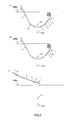
- FIG. 5 is a view for explaining an operation procedure of the implant device shown in FIG. 1.
- FIG. 1 is a plan view showing an embodiment of the implant device of the present invention.
- FIG. 2 is a plan view of the implant of the implant device shown in FIG.
- FIG. 3 is a plan view showing a state where a tube is inserted into the implant partway in the implant device shown in FIG. 1.
- 4 and 5 are diagrams for explaining an operation procedure of the implant device shown in FIG. In FIG. 4 and FIG. 5, the oblique lines in the living body are omitted for easy viewing.
- an implant device 10 is a device used for treating female urinary incontinence.
- an implant device 10 includes an implant 1 that is flexible, has a longitudinal shape, and can be embedded in a living body, and a sheath (tubular body) 5 into which the implant 1 can be inserted. ing.
- the sheath 5 is used by inserting the implant 1 when peeling the implant 1 embedded in the living body from the living tissue.
- the implant 1 is an instrument that can be implanted in a living body for the treatment of female urinary incontinence. That is, the implant 1 is an instrument that is embedded in a living body and supports the urethra (biological tissue), for example, an instrument that supports the urethra so that it does not move when the urethra tries to move toward the vaginal wall.
- the implant 1 is inserted into the sheath 5 when the implant 1 embedded in the living body is peeled from the living tissue.
- the implant 1 has a main body portion 2 and a pair of guide portions 3 provided at both ends in the longitudinal direction of the main body portion 2.
- the overall shape of the main body 2 is a band (plate), that is, a rectangle.
- the main body 2 has a plurality of warps 41 extending in the longitudinal direction and a plurality of wefts (wefts for main body) intersecting with the warps 41 and has a net shape.
- the warp yarn 41 and the weft yarn 42 are orthogonal to each other. Needless to say, the angle formed by the warp yarn 41 and the weft yarn 42 is not limited to 90 °.
- Such a main body 2 can be constituted by a braided body in which a warp yarn 41 and a weft yarn 42 are crossed, that is, a braided body.
- the end portion of the weft thread 42 is fixed to the warp thread 41 at the end portion of the main body 2 in the width direction (vertical direction in FIG. 2).
- Examples of the warp yarn 41 and the weft yarn 42 include, for example, a circular cross section, a flat cross section, that is, a belt (ribbon).
- warp yarn 41 and the weft yarn 42 are not limited to being knitted but may be integrally formed, for example.
- the dimensions of the main body 2 are not particularly limited and are appropriately set according to various conditions.
- the length in the longitudinal direction is preferably about 10 to 600 mm, more preferably about 30 to 300 mm.
- the length of the main body 2 in the vertical direction in FIGS. 1 and 2, that is, the width W1 in the direction perpendicular to the longitudinal direction of the main body 2 is about 2 to 30 mm. Preferably, it is about 5 to 15 mm.
- the ratio of the mesh portion of the main body 2, that is, the opening is not particularly limited, and is appropriately set according to various conditions, but is preferably about 20 to 95%, and preferably 50 to 90 More preferably, it is about%. Thereby, when accommodating in the sheath 5, supporting a urethra more reliably, it can deform
- Each guide part 3 is provided at both ends in the longitudinal direction of the main body part 2, and a plurality of warp threads 41 are extended and assembled. That is, the warp yarn 41 constituting the main body portion 2 and the warp yarn 41 constituting the guide portion 3 are continuous. Moreover, in this embodiment, all the warp threads 41 of the main body portion 2 are extended to constitute the guide portions 3. That is, the number of warp yarns 41 in the main body portion 2 is equal to the number of warp yarns 41 in the guide portion 3.
- the main body 2 and the guide portion at both ends in the width direction of the implant 1 Therefore, when the implant 1 is inserted into the sheath 5, the implant 1 can be inserted smoothly.
- each guide part 3 does not have a weft. Thereby, it becomes difficult to form unevenness in the guide portion 3, and when the implant 1 is inserted into the sheath 5, the implant 1 can be smoothly inserted.
- each guide part 3 since the structure of each guide part 3 is the same, below, the one guide part 3 is demonstrated typically.
- the guide portion 3 includes a string-like traction portion 32 capable of pulling the main body portion 2 and a taper portion 31 disposed between the traction portion 32 and the main body portion 2.
- the length of the guide portion 3 in the vertical direction in FIGS. 1 and 2, that is, the width W 2 that is the length in the direction perpendicular to the longitudinal direction of the guide portion 3 is smaller than the width W 1 of the main body portion 2. Is set.
- the taper portion 31 is a function of guiding the main body portion 2 to be deformed into a shape to be inserted into the sheath 5 before the main body portion 2 and inserted into the sheath 5 when the main body portion 2 is inserted into the sheath 5. I am doing.
- the width W2 of the taper portion 31 is gradually reduced toward the traction portion 32 side. Note that the inclination angle ⁇ of the taper portion 31 may be constant or may vary.
- the inclination angle ⁇ of the taper portion 31 is not particularly limited and is appropriately set according to various conditions, but is preferably about 2 to 80 °, and preferably about 20 to 45 °. More preferred. Thereby, the taper part 31 can be inserted into the sheath 5 more smoothly.
- the end portion of the guide portion 3 on the main body portion 2 side that is, the tapered portion 31 is curved in a concave shape so that both end portions in the width direction are located on the front side with respect to the paper surface of FIG. ing.
- the end portion of the main body portion 2 on the guide portion 3 side is similarly curved in a concave shape due to the curvature of the tapered portion 31.
- the towing unit 32 is a twisted warp yarn 41.
- the traction unit 32 is formed by twisting each warp yarn 41 into three parts and knitting each, that is, a braid. Thereby, the intensity
- each warp thread 41 of the traction unit 32 is not limited to braiding, and for example, it may be two or four or more. Moreover, each warp thread 41 of the traction part 32 does not need to be knitted.
- the diameter is preferably about 0.1 to 3 mm, more preferably about 0.2 to 2 mm. .
- the width is preferably about 0.5 to 10 mm, and more preferably about 2 to 5 mm.
- the thickness is preferably about 0.1 to 5 mm, more preferably about 1 to 3 mm.
- constituent material of the implant 1, that is, the constituent material of the warp yarn 41 and the weft yarn 42 is not particularly limited, and for example, various resin materials having biocompatibility such as polypropylene, fibers, and the like can be used.
- the sheath 5 has flexibility.
- the dimension of the sheath 5 is not particularly limited and is appropriately set according to various conditions such as the dimension of the implant 1, but the inner diameter (diameter) is preferably about 1 to 10 mm. More preferably, it is about 5 mm.
- the outer diameter (diameter) is preferably about 1 to 15 mm, and more preferably about 2.5 to 5.5 mm.
- the constituent material of the sheath 5 is not particularly limited.
- resins polytetrafluoroethylene and the like
- various other elastomers for example, polyamide-based and polyester-based thermoplastic elastomers
- FIGS. 4 and 5 an example of a method for using the implant device 10 will be described with reference to FIGS. 4 and 5.
- a procedure for taking out the implant 1 embedded in the living body for the treatment of female urinary incontinence will be described.
- the implant 1 is embedded in a patient's living body.
- the main body portion 2 of the implant 1 is disposed so as to be located immediately below the urethra, that is, between the urethra and the vagina.
- the traction part 32 of each guide part 3 is inserted through the closing holes of the left and right pelvises, and the end part of each traction part 32 opposite to the main body part 2 is rounded or bent. In the state, it is disposed in the living body in the vicinity of the left and right buttocks.
- the implant 1 When the implant 1 is taken out from the living body, as shown in FIG. 4 (b), the body surface in the vicinity of one of the buttocks is slightly incised, and the end of the pulling portion 32 of the one guide portion 3 from the incision hole. Remove the part. Then, as shown in FIG. 4C, the traction portion 32 is inserted into the sheath 5, and the end portion of the traction portion 32 is pulled out from the opening at the end portion of the sheath 5.
- the sheath 5 is inserted into the living body while pulling the pulling portion 32 to the opposite side of the main body portion 2, and the main body portion along the pulling portion 32. Push it to the 2nd side. Thereby, the implant 1 is inserted into the sheath 5, and the implant 1 is peeled from the living tissue by the sheath 5.
- the tapered portion 31 is inserted into the sheath 5 following the pulling portion 32 of the guide portion 3.
- the tapered portion 31 is curved in a concave shape, the tapered portion 31 is smoothly inserted into the sheath 5 and further curved, that is, curled and folded (see FIG. 3).
- the main body portion 2 is inserted into the sheath 5.
- the main body 2 is bent by the bending of the taper portion 31, and thereby smoothly inserted into the sheath 5 and further bent in the sheath 5, that is, curled and folded (see FIG. 3).
- the subsequent portion of the main body 2 is similarly bent by the bending of the main body 2 on the near side, so that it is smoothly inserted into the sheath 5 and further bent in the sheath 5, that is, rounded. Folded. Thereafter, such an operation is continuously repeated, and the entire main body 2 is inserted into the sheath 5.
- the entire main body 2 is peeled from the living tissue.
- the guide portion 3 does not need to be actively peeled off by the sheath 5.
- the pulling portion 32 is pulled, the sheath 5 and the implant 1 are extracted from the living body, a predetermined treatment is performed, and the procedure is finished.
- the tension of the implant 1 may be adjusted while the implant 1 is embedded in the living body. In this case, after the entire body 2 of the implant 1 is peeled from the living tissue by the sheath 5, the tension of the implant 1 is adjusted. In adjusting the tension of the implant, for example, when urine obstruction is caused by the implant 1, the sheath 5 is used to move the main body 2 away from the urethra to reduce the tension of the implant 1. .
- the implant device 10 when the implant 1 embedded in the living body is peeled from the living tissue, the surface of the living body in the vicinity of the end portion of the pulling portion 32 of the implant 1 is cut small. It can be handled only by an invasive technique, and it is not necessary to make a large incision in the vaginal wall.
- the main body 2 of the implant 1 when the main body 2 of the implant 1 is inserted into the sheath 5, the main body 2 can be inserted into the sheath 5 easily and smoothly by the tapered portion 31.
- the taper portion 31 does not have a weft, a step or the like hardly occurs in the taper portion 31, and the taper portion 31 can be inserted into the sheath 5 easily and smoothly.
- the tapered portion 31 is curved in a concave shape, the main body portion 2 can be smoothly inserted into the sheath 5 by this.
- the main body 2 and the tapered portion are formed at both ends in the width direction of the implant 1.
- the boundary part with 31 becomes smooth, and, thereby, the main-body part 2 can be smoothly inserted into the sheath 5.
- the implant and the implant device of the present invention have been described based on the illustrated embodiment.
- the present invention is not limited to this, and the configuration of each part is an arbitrary configuration having the same function. Can be replaced.
- any other component may be added to the present invention.
- a hard tube may be used as the tube.
- the guide portion 3 may be configured by extending a part of the plurality of warp threads 41 constituting the main body portion 2 and collecting them. That is, the number of warp threads 41 in the guide part 3 may be smaller than the number of warp threads 41 in the main body part 2.
- the guide portion 3 may be provided with a lower density than the weft yarn 42 in the main body portion 2 and may have a weft yarn (weft yarn for guide portion) that intersects the warp yarn 41.
- the guide portion 3 may be provided only at one end portion in the longitudinal direction of the main body portion 2.
- the contour shape of the main body 2 is not limited to a rectangle, and examples thereof include other polygons such as a pentagon, a circle, an ellipse, and the like.
- the implant and the implant device of the present invention when the implant and the implant device of the present invention are applied to the treatment of urinary incontinence in women, the application of the implant and the implant device particularly in the TOT operation has been described.
- the pubic urethra ligament is assumed to be a ligament that passes through both sides of the pubic bone and under the urethra, and is applied to implants and implant devices used in TVT surgery that reinforces the U shape using an implant. May be.
- the use of the implant and implant device of the present invention is not limited thereto. Other applications include, for example, implants and implant devices for the treatment of male urinary incontinence.
Abstract
The implant (1) is flexible, has a long shape and can be implanted in a living body. The implant (1) comprises: a main body (2) comprising multiple warp threads (41) that extend in the longitudinal direction and multiple weft threads (42) that intersect with the warp threads (41), said main body (2) forming a sheet shape; and a pair of guide sections (3) provided on both ends of the main body (2) in the longitudinal direction. Each guide section (3) is provided with a cord-shaped pulling section (32) by which the main body (2) can be pulled and a tapered section (31) disposed between the pulling section (32) and the main body (2). Each guide section (3) is configured from all of the multiple warp threads (41) being extended and gathered. The width (W2) of each guide section (3) is smaller than the width (W1) of the main body (2). Neither of the guide sections (3) has weft threads.
Description
本発明は、インプラントおよびインプラント装置に関するものである。
The present invention relates to an implant and an implant device.
尿失禁、特に、腹圧性尿失禁になると、通常の運動中や、笑い、咳、くしゃみ等により腹圧がかかることで、尿漏れが生じる。この原因は、例えば、出産等により、尿道を支える筋肉である骨盤底筋が緩むこと等が挙げられる。
Urinary incontinence, particularly stress urinary incontinence, urine leakage occurs due to abdominal pressure applied during normal exercise, laughing, coughing, sneezing, etc. The cause of this is, for example, that the pelvic floor muscle, which is a muscle that supports the urethra, is loosened due to childbirth and the like.
尿失禁の治療には、外科的療法が有効であり、例えば、「スリング」と呼ばれ、テープ状でかつ網状をなすインプラントを用い、スリングを体内に留置し、そのスリングで尿道を支持する(例えば、特許文献1参照)。スリングを体内に留置するには、術者がメスで膣壁を切開し、尿道と膣の間を剥離し、穿刺針を用いて、その剥離した部位と外部とを骨盤の閉鎖孔を介し連通させ、穿刺孔を形成する。そして、このような穿刺孔を用いて、スリングを生体内の尿道の直下に留置するTOT手術と呼ばれる方法がある。
Surgical therapy is effective for the treatment of urinary incontinence. For example, it is called a “sling”, and a tape-like and net-like implant is used, and the sling is placed in the body and the urethra is supported by the sling ( For example, see Patent Document 1). To place the sling in the body, the surgeon incises the vagina wall with a scalpel, peels off the space between the urethra and the vagina, and uses the puncture needle to communicate the peeled site and the outside through the pelvic obturator. And a puncture hole is formed. There is a method called TOT surgery in which such a puncture hole is used to place a sling directly under the urethra in a living body.
しかしながら、スリングを留置した後、そのスリングにより尿閉塞が生じたり、また、「びらん」と呼ばれ、スリングが膣壁を破って膣内に露出してしまう等の合併症が生じる虞がある。このような合併症が生じた場合は、従来のスリングでは、そのスリングによる尿道の締め付け力を弱めたり、また、生体内のスリングの位置を変更することができないので、そのスリングを生体内から取り出す必要がある。スリングを生体内から取り出す場合は、再度、術者がメスで、スリングが留置されている部位に対応する膣壁全体を切開し、スリングを生体組織から剥離する。このため、スリングを生体内から取り出す際、侵襲が大きく、患者への負担が大きいという欠点がある。また、術者による手技の最中にメスで尿道等を損傷する虞がある。
However, after indwelling the sling, the sling may cause urinary obstruction, or it may be called “erosion”, and complications such as the sling breaking through the vagina wall and being exposed in the vagina may occur. When such complications occur, the conventional sling cannot weaken the tightening force of the urethra due to the sling or change the position of the sling in the living body, so that the sling is taken out from the living body. There is a need. When the sling is taken out from the living body, the operator again uses a scalpel to incise the entire vaginal wall corresponding to the site where the sling is placed, and peel the sling from the living tissue. For this reason, when taking out a sling from in-vivo, there exists a fault that invasiveness is large and a burden to a patient is large. In addition, the urethra and the like may be damaged with a scalpel during the procedure by the operator.
本発明の目的は、生体内に埋設されたインプラントを生体組織から剥離する際、患者の負担が少なく、患者の安全性が高いインプラントおよびインプラント装置を提供することにある。
An object of the present invention is to provide an implant and an implant device that have a low patient burden and high patient safety when an implant embedded in a living body is peeled from a living tissue.
このような目的は、下記(1)~(14)の本発明により達成される。
(1) 可撓性を有し、長手形状をなし、生体内に埋設可能なインプラントであって、
長手方向に延在する複数の縦糸と、該縦糸と交差する複数の本体部用横糸とを有し、板状をなす本体部と、
前記本体部の長手方向の少なくとも一方の端部に設けられ、前記複数の縦糸の一部または全部が延長し、集合して構成されたガイド部とを備え、
前記ガイド部の幅は、前記本体部の幅よりも小さく、
前記ガイド部は、前記本体部用横糸よりも小さい配設密度で設けられ、前記縦糸と交差するガイド部用横糸を有するか、または該ガイド部用横糸を有していないことを特徴とするインプラント。 Such an object is achieved by the present inventions (1) to (14) below.
(1) An implant that has flexibility, has a longitudinal shape, and can be embedded in a living body,
A plurality of warp yarns extending in the longitudinal direction; and a plurality of weft yarns for main body portions intersecting with the warp yarns;
A guide portion provided at at least one end in the longitudinal direction of the main body portion, wherein a part or all of the plurality of warp yarns are extended and assembled,
The width of the guide portion is smaller than the width of the main body portion,
The implant is characterized in that the guide portion is provided with a density lower than that of the main body portion weft and has a guide portion weft that intersects the warp yarn or does not have the guide portion weft. .
(2) 前記ガイド部の前記本体部側の端部は、凹状に湾曲している上記(1)に記載のインプラント。
(2) The implant according to (1), wherein an end of the guide portion on the main body side is curved in a concave shape.
(3) 前記本体部の幅方向の両端部の前記縦糸は、延長して前記ガイド部の少なくとも一部を構成している上記(1)または(2)に記載のインプラント。
(3) The implant according to (1) or (2), wherein the warp yarns at both ends in the width direction of the main body portion are extended to constitute at least a part of the guide portion.
(4) 可撓性を有し、長手形状をなし、生体内に埋設可能なインプラントであって、
長手方向に延在する複数の縦糸と、該縦糸と交差する複数の本体部用横糸とを有し、板状をなす本体部と、
前記本体部の長手方向の少なくとも一方の端部に設けられ、前記複数の縦糸の一部または全部が延長し、集合して構成されたガイド部とを備え、
前記ガイド部の幅は、前記本体部の幅よりも小さく、
前記ガイド部の前記本体部側の端部は、凹状に湾曲していることを特徴とするインプラント。 (4) An implant that has flexibility, has a longitudinal shape, and can be embedded in a living body,
A plurality of warp yarns extending in the longitudinal direction; and a plurality of weft yarns for main body portions intersecting with the warp yarns;
A guide portion provided at at least one end in the longitudinal direction of the main body portion, wherein a part or all of the plurality of warp yarns are extended and assembled,
The width of the guide portion is smaller than the width of the main body portion,
An end portion of the guide portion on the main body side is curved in a concave shape.
(5) 前記本体部の幅方向の両端部の前記縦糸は、延長して前記ガイド部の少なくとも一部を構成している上記(4)に記載のインプラント。
(5) The implant according to (4), wherein the warp yarns at both ends in the width direction of the main body portion are extended to constitute at least a part of the guide portion.
(6) 可撓性を有し、長手形状をなし、生体内に埋設可能なインプラントであって、
長手方向に延在する複数の縦糸と、該縦糸と交差する複数の本体部用横糸とを有し、板状をなす本体部と、
前記本体部の長手方向の少なくとも一方の端部に設けられ、前記複数の縦糸の一部または全部が延長し、集合して構成されたガイド部とを備え、
前記ガイド部の幅は、前記本体部の幅よりも小さく、
前記本体部の幅方向の両端部の前記縦糸は、延長して前記ガイド部の少なくとも一部を構成していることを特徴とするインプラント。 (6) An implant that has flexibility, has a longitudinal shape, and can be embedded in a living body,
A plurality of warp yarns extending in the longitudinal direction; and a plurality of weft yarns for main body portions intersecting with the warp yarns;
A guide portion provided at at least one end in the longitudinal direction of the main body portion, wherein a part or all of the plurality of warp yarns are extended and assembled,
The width of the guide portion is smaller than the width of the main body portion,
The implant characterized in that the warp yarns at both ends in the width direction of the main body portion extend to constitute at least a part of the guide portion.
(7) 前記ガイド部は、前記本体部を引っ張ることが可能な紐状の牽引部と、該牽引部と前記本体部との間に配置され、幅が前記牽引部側に向って漸減するテーパ部とを備える上記(1)ないし(6)のいずれかに記載のインプラント。
(7) The guide portion is a string-like traction portion capable of pulling the main body portion, and is arranged between the traction portion and the main body portion, and has a taper whose width gradually decreases toward the traction portion side. The implant according to any one of the above (1) to (6).
(8) 前記牽引部は、前記縦糸を撚ったものである上記(7)に記載のインプラント。
(8) The implant according to (7), wherein the traction portion is a twisted warp.
(9) 前記テーパ部は、前記本体部を管体内に挿入する際に、前記本体部よりも先に前記管体内に挿入され、前記本体部を前記管体内に挿入する形状に変形するよう誘導するものである上記(7)または(8)に記載のインプラント。
(9) The tapered portion is inserted into the tubular body before the main body portion when the main body portion is inserted into the tubular body, and is guided so as to be deformed into a shape for inserting the main body portion into the tubular body. The implant according to the above (7) or (8).
(10) 前記本体部における前記縦糸の本数と、前記ガイド部における前記縦糸の本数とが等しい上記(1)ないし(9)のいずれかに記載のインプラント。
(10) The implant according to any one of (1) to (9), wherein the number of the warp yarns in the main body portion is equal to the number of the warp yarns in the guide portion.
(11) 当該インプラントは、尿失禁の治療に用いられるものであり、
前記本体部は、尿道を支持可能なものである上記(1)ないし(10)のいずれかに記載のインプラント。 (11) The implant is used to treat urinary incontinence,
The implant according to any one of (1) to (10), wherein the main body is capable of supporting the urethra.
前記本体部は、尿道を支持可能なものである上記(1)ないし(10)のいずれかに記載のインプラント。 (11) The implant is used to treat urinary incontinence,
The implant according to any one of (1) to (10), wherein the main body is capable of supporting the urethra.
(12) 当該インプラントは、当該インプラントを生体組織から剥離する際に管体内に挿入されるものである上記(1)ないし(11)のいずれかに記載のインプラント。
(12) The implant according to any one of (1) to (11), wherein the implant is inserted into a tubular body when the implant is detached from a living tissue.
(13) 上記(1)ないし(12)のいずれかに記載のインプラントと、
前記インプラントが挿入可能な管体とを備えることを特徴とするインプラント装置。 (13) The implant according to any one of (1) to (12) above,
An implant device comprising: a tube body into which the implant can be inserted.
前記インプラントが挿入可能な管体とを備えることを特徴とするインプラント装置。 (13) The implant according to any one of (1) to (12) above,
An implant device comprising: a tube body into which the implant can be inserted.
(14) 前記管体は、前記インプラントを生体組織から剥離する際に、前記インプラントを挿入して使用するものである上記(13)に記載のインプラント装置。
(14) The implant device according to (13), wherein the tubular body is used by inserting the implant when peeling the implant from a living tissue.
本発明によれば、生体内に埋設されたインプラントを生体組織から剥離する際、ガイド部により、容易かつ低侵襲に、インプラントの本体部を管体内に挿入することができ、管体をインプラントに沿って移動させることにより、管体によりインプラントを生体組織から剥離することができる。このため、患者の負担が少なく、患者の安全性が高い。そして、インプラントを生体組織から剥離した後、インプラントを生体内から取り出したり、また、インプラントの位置を調整することができる。
According to the present invention, when the implant embedded in the living body is peeled from the living tissue, the main body of the implant can be easily and less invasively inserted into the tubular body by the guide portion, and the tubular body is used as the implant. By moving along, the implant can be detached from the living tissue by the tube. For this reason, there is little burden on a patient and patient safety is high. Then, after the implant is peeled from the living tissue, the implant can be taken out from the living body, and the position of the implant can be adjusted.
以下、本発明のインプラントおよびインプラント装置を添付図面に示す好適な実施形態に基づいて詳細に説明する。
Hereinafter, an implant and an implant device of the present invention will be described in detail based on preferred embodiments shown in the accompanying drawings.
図1は、本発明のインプラント装置の実施形態を示す平面図である。図2は、図1に示すインプラント装置のインプラントの平面図である。図3は、図1に示すインプラント装置においてインプラントにチューブを途中まで挿入した状態を示す平面図である。図4、図5は、図1に示すインプラント装置の操作手順を説明するための図である。
なお、図4、図5では、見易いように、生体における斜線を省略する。 FIG. 1 is a plan view showing an embodiment of the implant device of the present invention. FIG. 2 is a plan view of the implant of the implant device shown in FIG. FIG. 3 is a plan view showing a state where a tube is inserted into the implant partway in the implant device shown in FIG. 1. 4 and 5 are diagrams for explaining an operation procedure of the implant device shown in FIG.
In FIG. 4 and FIG. 5, the oblique lines in the living body are omitted for easy viewing.
これらの図に示すインプラント装置10は、女性の尿失禁の治療に用いる装置である。図1に示すように、インプラント装置10は、可撓性を有し、長手形状をなし、生体内に埋設可能なインプラント1と、そのインプラント1が挿入可能なシース(管体)5とを備えている。
The implant device 10 shown in these drawings is a device used for treating female urinary incontinence. As shown in FIG. 1, an implant device 10 includes an implant 1 that is flexible, has a longitudinal shape, and can be embedded in a living body, and a sheath (tubular body) 5 into which the implant 1 can be inserted. ing.
シース5は、生体内に埋設されたインプラント1を生体組織から剥離する際に、インプラント1を挿入して使用するものである。また、インプラント1は、女性の尿失禁の治療のための生体内に埋設可能な器具である。すなわち、インプラント1は、生体内に埋設されて尿道(生体組織)を支持する器具、例えば尿道が膣壁側に移動しようとしたときに、その尿道を移動しないように支持する器具である。なお、インプラント1は、生体内に埋設されたそのインプラント1を生体組織から剥離する際にシース5内に挿入されるものである。
The sheath 5 is used by inserting the implant 1 when peeling the implant 1 embedded in the living body from the living tissue. The implant 1 is an instrument that can be implanted in a living body for the treatment of female urinary incontinence. That is, the implant 1 is an instrument that is embedded in a living body and supports the urethra (biological tissue), for example, an instrument that supports the urethra so that it does not move when the urethra tries to move toward the vaginal wall. The implant 1 is inserted into the sheath 5 when the implant 1 embedded in the living body is peeled from the living tissue.
図1および図2に示すように、インプラント1は、本体部2と、本体部2の長手方向の両端部に設けられた1対のガイド部3とを有している。
As shown in FIGS. 1 and 2, the implant 1 has a main body portion 2 and a pair of guide portions 3 provided at both ends in the longitudinal direction of the main body portion 2.
本体部2の全体形状は、帯状(板状)、すなわち長方形をなしている。また、本体部2は、長手方向に延在する複数の縦糸41と、縦糸41と交差する複数の横糸(本体部用横糸)42とを有し、網状をなしている。本実施形態では、縦糸41と横糸42とは直交している。なお、縦糸41と横糸42とのなす角は、90°に限定されないことは、言うまでもない。
The overall shape of the main body 2 is a band (plate), that is, a rectangle. The main body 2 has a plurality of warps 41 extending in the longitudinal direction and a plurality of wefts (wefts for main body) intersecting with the warps 41 and has a net shape. In the present embodiment, the warp yarn 41 and the weft yarn 42 are orthogonal to each other. Needless to say, the angle formed by the warp yarn 41 and the weft yarn 42 is not limited to 90 °.
このような本体部2は、縦糸41と横糸42とを交差させて網状(格子状)に編んだもの、すなわち、網状の編組体で構成することができる。なお、横糸42の端部は、本体部2の幅方向(図2中の上下方向)の端部の縦糸41に固着されている。
Such a main body 2 can be constituted by a braided body in which a warp yarn 41 and a weft yarn 42 are crossed, that is, a braided body. The end portion of the weft thread 42 is fixed to the warp thread 41 at the end portion of the main body 2 in the width direction (vertical direction in FIG. 2).
縦糸41および横糸42としては、それぞれ、例えば、その横断面形状が円形のものや、横断面形状が偏平形状のもの、すなわち帯状(リボン状)のもの等が挙げられる。
Examples of the warp yarn 41 and the weft yarn 42 include, for example, a circular cross section, a flat cross section, that is, a belt (ribbon).
なお、縦糸41と横糸42とは、編まれている場合に限らず、例えば、一体的に形成されていてもよい。
Note that the warp yarn 41 and the weft yarn 42 are not limited to being knitted but may be integrally formed, for example.
この本体部2の寸法は、特に限定されず、諸条件に応じて適宜設定されるものであるが、本体部2の図1および図2中の左右方向の長さ、すなわち、本体部2の長手方向の長さは、10~600mm程度であることが好ましく、30~300mm程度であることがより好ましい。
The dimensions of the main body 2 are not particularly limited and are appropriately set according to various conditions. The length of the main body 2 in the left-right direction in FIGS. The length in the longitudinal direction is preferably about 10 to 600 mm, more preferably about 30 to 300 mm.
また、本体部2の図1および図2中の上下方向の長さ、すなわち、本体部2の長手方向に対して垂直な方向の長さである幅W1は、2~30mm程度であることが好ましく、5~15mm程度であることがより好ましい。
Also, the length of the main body 2 in the vertical direction in FIGS. 1 and 2, that is, the width W1 in the direction perpendicular to the longitudinal direction of the main body 2 is about 2 to 30 mm. Preferably, it is about 5 to 15 mm.
また、本体部2の網目部分、すなわち、開口の占める割合は、特に限定されず、諸条件に応じて適宜設定されるものであるが、20~95%程度であることが好ましく、50~90%程度であることがより好ましい。これにより、より確実に尿道を支持しつつ、シース5内に収納する際、より円滑に変形し、収納することができる。
Further, the ratio of the mesh portion of the main body 2, that is, the opening, is not particularly limited, and is appropriately set according to various conditions, but is preferably about 20 to 95%, and preferably 50 to 90 More preferably, it is about%. Thereby, when accommodating in the sheath 5, supporting a urethra more reliably, it can deform | transform and accommodate more smoothly.
各ガイド部3は、本体部2の長手方向の両端部に設けられ、複数の縦糸41が延長し、集合したものである。すなわち、本体部2を構成する縦糸41とガイド部3を構成する縦糸41とは連続している。また、本実施形態では、本体部2の各縦糸41の全部が延長して各ガイド部3を構成している。すなわち、本体部2における縦糸41の本数と、ガイド部3における縦糸41の本数とは、等しい。
Each guide part 3 is provided at both ends in the longitudinal direction of the main body part 2, and a plurality of warp threads 41 are extended and assembled. That is, the warp yarn 41 constituting the main body portion 2 and the warp yarn 41 constituting the guide portion 3 are continuous. Moreover, in this embodiment, all the warp threads 41 of the main body portion 2 are extended to constitute the guide portions 3. That is, the number of warp yarns 41 in the main body portion 2 is equal to the number of warp yarns 41 in the guide portion 3.
この場合、特に、本体部2の幅方向の両端部の縦糸41が延長してガイド部3の一部を構成しているので、インプラント1の幅方向の両端部において、本体部2とガイド部3との境界部が滑らかになり、これにより、シース5内にインプラント1を挿入する際、インプラント1を円滑に挿入することができる。
In this case, in particular, since the warp threads 41 at both ends in the width direction of the main body 2 extend to form a part of the guide portion 3, the main body 2 and the guide portion at both ends in the width direction of the implant 1 Therefore, when the implant 1 is inserted into the sheath 5, the implant 1 can be inserted smoothly.
また、各ガイド部3は、横糸を有していない。これにより、ガイド部3に凹凸が形成され難くなり、シース5内にインプラント1を挿入する際、インプラント1を円滑に挿入することができる。
Moreover, each guide part 3 does not have a weft. Thereby, it becomes difficult to form unevenness in the guide portion 3, and when the implant 1 is inserted into the sheath 5, the implant 1 can be smoothly inserted.
なお、各ガイド部3の構成は、同様であるので、以下では、代表的に、一方のガイド部3について説明する。
In addition, since the structure of each guide part 3 is the same, below, the one guide part 3 is demonstrated typically.
ガイド部3は、本体部2を引っ張ることが可能な紐状の牽引部32と、牽引部32と本体部2との間に配置されたテーパ部31とを備えている。このガイド部3の図1および図2中の上下方向の長さ、すなわち、ガイド部3の長手方向に対して垂直な方向の長さである幅W2は、本体部2の幅W1よりも小さく設定されている。
The guide portion 3 includes a string-like traction portion 32 capable of pulling the main body portion 2 and a taper portion 31 disposed between the traction portion 32 and the main body portion 2. The length of the guide portion 3 in the vertical direction in FIGS. 1 and 2, that is, the width W 2 that is the length in the direction perpendicular to the longitudinal direction of the guide portion 3 is smaller than the width W 1 of the main body portion 2. Is set.
テーパ部31は、本体部2をシース5内に挿入する際に、本体部2よりも先にシース5内に挿入され、本体部2をシース5内に挿入する形状に変形するよう誘導する機能をしている。
The taper portion 31 is a function of guiding the main body portion 2 to be deformed into a shape to be inserted into the sheath 5 before the main body portion 2 and inserted into the sheath 5 when the main body portion 2 is inserted into the sheath 5. I am doing.
このテーパ部31の幅W2は、牽引部32側に向って漸減している。なお、このテーパ部31の傾斜角度θは、一定でもよく、また、変化していてもよい。
The width W2 of the taper portion 31 is gradually reduced toward the traction portion 32 side. Note that the inclination angle θ of the taper portion 31 may be constant or may vary.
また、テーパ部31の傾斜角度θは、特に限定されず、諸条件に応じて適宜設定されるものであるが、2~80°程度であることが好ましく、20~45°程度であることがより好ましい。これにより、テーパ部31は、より円滑にシース5内に挿入することができる。
Further, the inclination angle θ of the taper portion 31 is not particularly limited and is appropriately set according to various conditions, but is preferably about 2 to 80 °, and preferably about 20 to 45 °. More preferred. Thereby, the taper part 31 can be inserted into the sheath 5 more smoothly.
また、ガイド部3の本体部2側の端部、すなわち、テーパ部31は、その幅方向の両端部が中央部よりも図2の紙面に対して手前側に位置するように凹状に湾曲している。そして、本体部2のガイド部3側の端部は、前記テーパ部31の湾曲により、同様に凹状に湾曲している。これにより、シース5内にインプラント1を挿入する際、テーパ部31が丸まり易く、または、折り畳まれ易くなり、インプラント1を円滑に挿入することができる。
Further, the end portion of the guide portion 3 on the main body portion 2 side, that is, the tapered portion 31 is curved in a concave shape so that both end portions in the width direction are located on the front side with respect to the paper surface of FIG. ing. The end portion of the main body portion 2 on the guide portion 3 side is similarly curved in a concave shape due to the curvature of the tapered portion 31. Thereby, when inserting the implant 1 in the sheath 5, the taper part 31 becomes easy to be rounded or it is easy to be folded, and the implant 1 can be inserted smoothly.
牽引部32は、各縦糸41を撚ったものである。本実施形態では、牽引部32は、各縦糸41を3つに分けて撚り、各々を編んだもの、すなわち、三つ編みにしたものである。これにより、牽引部32の強度を高くすることができ、また、牽引部32の各縦糸41がバラバラになってしまうことを防止することができる。また、テーパ部31の幅W2は、牽引部32側に向って漸減して各縦糸41が編まれているため図2の紙面に対して手前側に位置するように凹状に湾曲している。
The towing unit 32 is a twisted warp yarn 41. In the present embodiment, the traction unit 32 is formed by twisting each warp yarn 41 into three parts and knitting each, that is, a braid. Thereby, the intensity | strength of the traction part 32 can be made high and it can prevent that each warp 41 of the traction part 32 falls apart. Further, the width W2 of the taper portion 31 is gradually reduced toward the pulling portion 32 side and each warp thread 41 is knitted so that the taper portion 31 is curved in a concave shape so as to be positioned on the near side with respect to the paper surface of FIG.
なお、牽引部32の各縦糸41の編み方は、三つ編みに限らず、例えば、二つ編でもよく、また、4つ以上に編んでもよい。また、牽引部32の各縦糸41は、編まれていなくてもよい。
In addition, the method of knitting each warp thread 41 of the traction unit 32 is not limited to braiding, and for example, it may be two or four or more. Moreover, each warp thread 41 of the traction part 32 does not need to be knitted.
前記縦糸41および横糸42は、それぞれ、その横断面形状が円形のものである場合、その直径は、0.1~3mm程度であることが好ましく、0.2~2mm程度であることがより好ましい。
When the cross-sectional shape of each of the warp yarn 41 and the weft yarn is circular, the diameter is preferably about 0.1 to 3 mm, more preferably about 0.2 to 2 mm. .
また、縦糸41および横糸42は、それぞれ、帯状のものである場合、その幅は、0.5~10mm程度であることが好ましく、2~5mm程度であることがより好ましい。また、厚さは、0.1~5mm程度であることが好ましく、1~3mm程度であることがより好ましい。
Further, when the warp yarn 41 and the weft yarn 42 are each in the form of a belt, the width is preferably about 0.5 to 10 mm, and more preferably about 2 to 5 mm. The thickness is preferably about 0.1 to 5 mm, more preferably about 1 to 3 mm.
また、インプラント1の構成材料、すなわち、縦糸41および横糸42の構成材料としては、特に限定されず、例えば、ポリプロピレン等のような生体適合性を有する各種樹脂材料、繊維等を用いることができる。
Further, the constituent material of the implant 1, that is, the constituent material of the warp yarn 41 and the weft yarn 42 is not particularly limited, and for example, various resin materials having biocompatibility such as polypropylene, fibers, and the like can be used.
シース5は、可撓性を有している。このシース5の寸法は、特に限定されず、インプラント1の寸法等の諸条件に応じて適宜設定されるものであるが、その内径(直径)は、1~10mm程度であることが好ましく、2~5mm程度であることがより好ましい。また、外径は、(直径)は、1~15mm程度であることが好ましく、2.5~5.5mm程度であることがより好ましい。
The sheath 5 has flexibility. The dimension of the sheath 5 is not particularly limited and is appropriately set according to various conditions such as the dimension of the implant 1, but the inner diameter (diameter) is preferably about 1 to 10 mm. More preferably, it is about 5 mm. The outer diameter (diameter) is preferably about 1 to 15 mm, and more preferably about 2.5 to 5.5 mm.
また、シース5の構成材料としては、特に限定されず、例えば、ポリエチレン、ポリプロピレン、エチレン-プロピレン共重合体、ポリ塩化ビニル、ポリエステル(PET、PBT、PEN等)、ポリアミド、ポリイミド、ポリウレタン、フッ素系樹脂(ポリテトラフルオロエチレン等)、その他各種のエラストマー(例えば、ポリアミド系、ポリエステル系等の熱可塑性エラストマー)等が挙げられ、これらのうちの1種または2種以上を組み合わせて用いることができる。
The constituent material of the sheath 5 is not particularly limited. For example, polyethylene, polypropylene, ethylene-propylene copolymer, polyvinyl chloride, polyester (PET, PBT, PEN, etc.), polyamide, polyimide, polyurethane, fluorine-based Examples thereof include resins (polytetrafluoroethylene and the like) and various other elastomers (for example, polyamide-based and polyester-based thermoplastic elastomers), and one or more of these can be used in combination.
次に、インプラント装置10の使用方法の一例について、図4および図5を参照しつつ説明する。ここでは、女性の尿失禁の治療のために生体内に埋設されたインプラント1を生体内から取り出す場合の手順について説明する。
Next, an example of a method for using the implant device 10 will be described with reference to FIGS. 4 and 5. Here, a procedure for taking out the implant 1 embedded in the living body for the treatment of female urinary incontinence will be described.
まず、図4(a)に示すように、インプラント1は、患者の生体内に埋設されている。この場合、インプラント1の本体部2は、尿道の直下、すなわち、尿道と膣との間に位置するように配置されている。また、各ガイド部3の牽引部32は、それぞれ、左右の骨盤の閉鎖孔を挿通し、各牽引部32の本体部2と反対側の端部は、それぞれ、丸められた状態または折り曲げられた状態で、左右の鼠蹊部の近傍の生体内に配置されている。
First, as shown in FIG. 4A, the implant 1 is embedded in a patient's living body. In this case, the main body portion 2 of the implant 1 is disposed so as to be located immediately below the urethra, that is, between the urethra and the vagina. Further, the traction part 32 of each guide part 3 is inserted through the closing holes of the left and right pelvises, and the end part of each traction part 32 opposite to the main body part 2 is rounded or bent. In the state, it is disposed in the living body in the vicinity of the left and right buttocks.
インプラント1を生体内から取り出す際は、図4(b)に示すように、一方の鼠蹊部の近傍の体表面を僅かに切開し、その切開孔から一方のガイド部3の牽引部32の端部を取り出す。そして、図4(c)に示すように、シース5内に、牽引部32を挿入し、シース5の端部の開口から、牽引部32の端部を引き出す。
When the implant 1 is taken out from the living body, as shown in FIG. 4 (b), the body surface in the vicinity of one of the buttocks is slightly incised, and the end of the pulling portion 32 of the one guide portion 3 from the incision hole. Remove the part. Then, as shown in FIG. 4C, the traction portion 32 is inserted into the sheath 5, and the end portion of the traction portion 32 is pulled out from the opening at the end portion of the sheath 5.
次に、図5(a)、図5(b)に示すように、牽引部32を本体部2と反対側に引っ張りつつ、シース5を生体内に挿入し、牽引部32に沿って本体部2側に押し進める。これにより、インプラント1がシース5内に挿入されてゆき、そのシース5により、インプラント1が生体組織から剥離される。
Next, as shown in FIGS. 5 (a) and 5 (b), the sheath 5 is inserted into the living body while pulling the pulling portion 32 to the opposite side of the main body portion 2, and the main body portion along the pulling portion 32. Push it to the 2nd side. Thereby, the implant 1 is inserted into the sheath 5, and the implant 1 is peeled from the living tissue by the sheath 5.
この場合、シース5をガイド部3の牽引部32に沿って本体部2側に押し進めると、ガイド部3の牽引部32に続いてテーパ部31がシース5内に挿入される。この際、テーパ部31は、凹状に湾曲しているので、円滑に、シース5内に挿入され、シース5内でさらに湾曲し、すなわち、丸まって折り畳まれる(図3参照)。
In this case, when the sheath 5 is pushed toward the main body 2 along the pulling portion 32 of the guide portion 3, the tapered portion 31 is inserted into the sheath 5 following the pulling portion 32 of the guide portion 3. At this time, since the tapered portion 31 is curved in a concave shape, the tapered portion 31 is smoothly inserted into the sheath 5 and further curved, that is, curled and folded (see FIG. 3).
そして、テーパ部31に続いて、本体部2がシース5内に挿入される。この際、本体部2は、テーパ部31の湾曲により湾曲し、これにより、円滑に、シース5内に挿入され、シース5内でさらに湾曲し、すなわち、丸まって折り畳まれる(図3参照)。また、本体部2の続きの部位は、同様に、手前側の本体部2の湾曲により湾曲し、これにより、円滑に、シース5内に挿入され、シース5内でさらに湾曲し、すなわち、丸まって折り畳まれる。以降、このような動作が連続的に繰り返され、本体部2全体がシース5内に挿入される。
Then, following the taper portion 31, the main body portion 2 is inserted into the sheath 5. At this time, the main body 2 is bent by the bending of the taper portion 31, and thereby smoothly inserted into the sheath 5 and further bent in the sheath 5, that is, curled and folded (see FIG. 3). Further, the subsequent portion of the main body 2 is similarly bent by the bending of the main body 2 on the near side, so that it is smoothly inserted into the sheath 5 and further bent in the sheath 5, that is, rounded. Folded. Thereafter, such an operation is continuously repeated, and the entire main body 2 is inserted into the sheath 5.
以上で、本体部2全体が生体組織から剥離される。なお、ガイド部3については、シース5で積極的に剥離する必要はない。
Thus, the entire main body 2 is peeled from the living tissue. The guide portion 3 does not need to be actively peeled off by the sheath 5.
次に、図5(c)に示すように、シース5とともに、牽引部32を引っ張り、シース5およびインプラント1を生体内から抜き取り、所定の処置を行って手技を終了する。
Next, as shown in FIG. 5C, together with the sheath 5, the pulling portion 32 is pulled, the sheath 5 and the implant 1 are extracted from the living body, a predetermined treatment is performed, and the procedure is finished.
なお、ここではインプラント1を生体内から取り出す場合の手順について説明したが、インプラント1を生体内に埋設したまま、そのインプラント1のテンションを調整してもよい。この場合は、シース5によりインプラント1の本体部2全体を生体組織から剥離した後、そのインプラント1のテンションを調整する。このインプラントのテンションの調整においては、例えば、インプラント1により尿閉塞が生じているときは、シース5を使用して、本体部2を尿道から離間するように移動させ、インプラント1のテンションを小さくする。
Although the procedure for removing the implant 1 from the living body has been described here, the tension of the implant 1 may be adjusted while the implant 1 is embedded in the living body. In this case, after the entire body 2 of the implant 1 is peeled from the living tissue by the sheath 5, the tension of the implant 1 is adjusted. In adjusting the tension of the implant, for example, when urine obstruction is caused by the implant 1, the sheath 5 is used to move the main body 2 away from the urethra to reduce the tension of the implant 1. .
以上説明したように、このインプラント装置10によれば、生体内に埋設されているインプラント1を生体組織から剥離する際、インプラント1の牽引部32の端部の近傍の生体表面を小さく切開する低侵襲の手技のみで対応することができ、膣壁を大きく切開する必要がないので、患者の負担が少なく、また、患者の安全性も高い。
As described above, according to the implant device 10, when the implant 1 embedded in the living body is peeled from the living tissue, the surface of the living body in the vicinity of the end portion of the pulling portion 32 of the implant 1 is cut small. It can be handled only by an invasive technique, and it is not necessary to make a large incision in the vaginal wall.
また、インプラント1の本体部2をシース5内に挿入する際は、テーパ部31により、容易かつ円滑に、本体部2をシース5内に挿入することができる。この際、テーパ部31は、横糸を有していないので、そのテーパ部31に段差等が生じ難く、容易かつ円滑に、テーパ部31をシース5内に挿入することができる。
Further, when the main body 2 of the implant 1 is inserted into the sheath 5, the main body 2 can be inserted into the sheath 5 easily and smoothly by the tapered portion 31. At this time, since the taper portion 31 does not have a weft, a step or the like hardly occurs in the taper portion 31, and the taper portion 31 can be inserted into the sheath 5 easily and smoothly.
また、テーパ部31は、凹状に湾曲しているので、これにより、円滑に本体部2をシース5内に挿入することができる。
Further, since the tapered portion 31 is curved in a concave shape, the main body portion 2 can be smoothly inserted into the sheath 5 by this.
また、本体部2の幅方向の両端部の縦糸41が延長してテーパ部31の幅方向の両端部を構成しているので、インプラント1の幅方向の両端部において、本体部2とテーパ部31との境界部が滑らかになり、これにより、円滑に本体部2をシース5内に挿入することができる。
In addition, since the warp threads 41 at both ends in the width direction of the main body 2 extend to form both ends in the width direction of the tapered portion 31, the main body 2 and the tapered portion are formed at both ends in the width direction of the implant 1. The boundary part with 31 becomes smooth, and, thereby, the main-body part 2 can be smoothly inserted into the sheath 5.
以上、本発明のインプラントおよびインプラント装置を、図示の実施形態に基づいて説明したが、本発明はこれに限定されるものではなく、各部の構成は、同様の機能を有する任意の構成のものに置換することができる。また、本発明に、他の任意の構成物が付加されていてもよい。
As described above, the implant and the implant device of the present invention have been described based on the illustrated embodiment. However, the present invention is not limited to this, and the configuration of each part is an arbitrary configuration having the same function. Can be replaced. In addition, any other component may be added to the present invention.
なお、本発明では、管体として、シース5に替えて、例えば、硬質の管体を用いてもよい。
In the present invention, instead of the sheath 5, for example, a hard tube may be used as the tube.
また、本発明では、ガイド部3は、本体部2を構成する複数の縦糸41の一部が延長し、集合して構成されたものであってもよい。すなわち、ガイド部3における縦糸41の本数は、本体部2における縦糸41の本数よりも少なくてもよい。
Further, in the present invention, the guide portion 3 may be configured by extending a part of the plurality of warp threads 41 constituting the main body portion 2 and collecting them. That is, the number of warp threads 41 in the guide part 3 may be smaller than the number of warp threads 41 in the main body part 2.
また、本発明では、ガイド部3は、本体部2における横糸42よりも小さい配設密度で設けられ、縦糸41と交差する横糸(ガイド部用横糸)を有していてもよい。
Further, in the present invention, the guide portion 3 may be provided with a lower density than the weft yarn 42 in the main body portion 2 and may have a weft yarn (weft yarn for guide portion) that intersects the warp yarn 41.
また、本発明では、ガイド部3は、本体部2の長手方向の一方の端部のみに設けられていてもよい。
In the present invention, the guide portion 3 may be provided only at one end portion in the longitudinal direction of the main body portion 2.
また、本発明では、本体部2の輪郭形状は、長方形に限らず、例えば、五角形等の他の多角形や、円形、楕円形等が挙げられる。
Further, in the present invention, the contour shape of the main body 2 is not limited to a rectangle, and examples thereof include other polygons such as a pentagon, a circle, an ellipse, and the like.
また、前記実施形態では、本発明のインプラントおよびインプラント装置を女性の尿失禁の治療のためのものに適用した場合、特に、TOT手術でのインプラントおよびインプラント装置の適用について説明したが、この腹圧性尿失禁に対する外科的治療法としては、恥骨尿道靭帯という恥骨の両側と尿道の下を通る靭帯を想定し、インプラントを用いU字型に補強するTVT手術で使用されるインプラントおよびインプラント装置に適用してもよい。また、本発明のインプラントおよびインプラント装置の用途は、それに限定されるものではない。なお、他の用途としては、例えば、男性の尿失禁の治療のためのインプラントおよびインプラント装置等が挙げられる。
In the above embodiment, when the implant and the implant device of the present invention are applied to the treatment of urinary incontinence in women, the application of the implant and the implant device particularly in the TOT operation has been described. As a surgical treatment for urinary incontinence, the pubic urethra ligament is assumed to be a ligament that passes through both sides of the pubic bone and under the urethra, and is applied to implants and implant devices used in TVT surgery that reinforces the U shape using an implant. May be. Moreover, the use of the implant and implant device of the present invention is not limited thereto. Other applications include, for example, implants and implant devices for the treatment of male urinary incontinence.
1 インプラント
2 本体部
3 ガイド部
31 テーパ部
32 牽引部
41 縦糸
42 横糸
5 シース
10 インプラント装置
100 尿道
200 膣 DESCRIPTION OFSYMBOLS 1 Implant 2 Main-body part 3 Guide part 31 Tapered part 32 Pulling part 41 Warp thread 42 Weft 5 Sheath 10 Implant apparatus 100 Urethra 200 Vagina
2 本体部
3 ガイド部
31 テーパ部
32 牽引部
41 縦糸
42 横糸
5 シース
10 インプラント装置
100 尿道
200 膣 DESCRIPTION OF
Claims (14)
- 可撓性を有し、長手形状をなし、生体内に埋設可能なインプラントであって、
長手方向に延在する複数の縦糸と、該縦糸と交差する複数の本体部用横糸とを有し、板状をなす本体部と、
前記本体部の長手方向の少なくとも一方の端部に設けられ、前記複数の縦糸の一部または全部が延長し、集合して構成されたガイド部とを備え、
前記ガイド部の幅は、前記本体部の幅よりも小さく、
前記ガイド部は、前記本体部用横糸よりも小さい配設密度で設けられ、前記縦糸と交差するガイド部用横糸を有するか、または該ガイド部用横糸を有していないことを特徴とするインプラント。 An implant that has flexibility, has a longitudinal shape, and can be embedded in a living body,
A plurality of warp yarns extending in the longitudinal direction; and a plurality of weft yarns for main body portions intersecting with the warp yarns;
A guide portion provided at at least one end in the longitudinal direction of the main body portion, wherein a part or all of the plurality of warp yarns are extended and assembled,
The width of the guide portion is smaller than the width of the main body portion,
The implant is characterized in that the guide portion is provided with a density lower than that of the main body portion weft and has a guide portion weft that intersects the warp yarn or does not have the guide portion weft. . - 前記ガイド部の前記本体部側の端部は、凹状に湾曲している請求項1に記載のインプラント。 The implant according to claim 1, wherein an end of the guide portion on the main body side is curved in a concave shape.
- 前記本体部の幅方向の両端部の前記縦糸は、延長して前記ガイド部の少なくとも一部を構成している請求項1または2に記載のインプラント。 The implant according to claim 1 or 2, wherein the warp yarns at both ends in the width direction of the main body portion are extended to constitute at least a part of the guide portion.
- 可撓性を有し、長手形状をなし、生体内に埋設可能なインプラントであって、
長手方向に延在する複数の縦糸と、該縦糸と交差する複数の本体部用横糸とを有し、板状をなす本体部と、
前記本体部の長手方向の少なくとも一方の端部に設けられ、前記複数の縦糸の一部または全部が延長し、集合して構成されたガイド部とを備え、
前記ガイド部の幅は、前記本体部の幅よりも小さく、
前記ガイド部の前記本体部側の端部は、凹状に湾曲していることを特徴とするインプラント。 An implant that has flexibility, has a longitudinal shape, and can be embedded in a living body,
A plurality of warp yarns extending in the longitudinal direction; and a plurality of weft yarns for main body portions intersecting with the warp yarns;
A guide portion provided at at least one end in the longitudinal direction of the main body portion, wherein a part or all of the plurality of warp yarns are extended and assembled,
The width of the guide portion is smaller than the width of the main body portion,
An end portion of the guide portion on the main body side is curved in a concave shape. - 前記本体部の幅方向の両端部の前記縦糸は、延長して前記ガイド部の少なくとも一部を構成している請求項4に記載のインプラント。 The implant according to claim 4, wherein the warp yarns at both ends in the width direction of the main body portion extend to constitute at least a part of the guide portion.
- 可撓性を有し、長手形状をなし、生体内に埋設可能なインプラントであって、
長手方向に延在する複数の縦糸と、該縦糸と交差する複数の本体部用横糸とを有し、板状をなす本体部と、
前記本体部の長手方向の少なくとも一方の端部に設けられ、前記複数の縦糸の一部または全部が延長し、集合して構成されたガイド部とを備え、
前記ガイド部の幅は、前記本体部の幅よりも小さく、
前記本体部の幅方向の両端部の前記縦糸は、延長して前記ガイド部の少なくとも一部を構成していることを特徴とするインプラント。 An implant that has flexibility, has a longitudinal shape, and can be embedded in a living body,
A plurality of warp yarns extending in the longitudinal direction; and a plurality of weft yarns for main body portions intersecting with the warp yarns;
A guide portion provided at at least one end in the longitudinal direction of the main body portion, wherein a part or all of the plurality of warp yarns are extended and assembled,
The width of the guide portion is smaller than the width of the main body portion,
The implant characterized in that the warp yarns at both ends in the width direction of the main body portion extend to constitute at least a part of the guide portion. - 前記ガイド部は、前記本体部を引っ張ることが可能な紐状の牽引部と、該牽引部と前記本体部との間に配置され、幅が前記牽引部側に向って漸減するテーパ部とを備える請求項1ないし6のいずれか一項に記載のインプラント。 The guide portion includes a string-like traction portion capable of pulling the main body portion, and a tapered portion that is disposed between the traction portion and the main body portion and has a width that gradually decreases toward the traction portion side. The implant according to any one of claims 1 to 6.
- 前記牽引部は、前記縦糸を撚ったものである請求項7に記載のインプラント。 The implant according to claim 7, wherein the pulling portion is a twist of the warp yarn.
- 前記テーパ部は、前記本体部を管体内に挿入する際に、前記本体部よりも先に前記管体内に挿入され、前記本体部を前記管体内に挿入する形状に変形するよう誘導するものである請求項7または8に記載のインプラント。 The tapered portion is inserted into the tubular body before the main body portion when the main body portion is inserted into the tubular body, and is guided to be deformed into a shape for inserting the main body portion into the tubular body. The implant according to claim 7 or 8.
- 前記本体部における前記縦糸の本数と、前記ガイド部における前記縦糸の本数とが等しい請求項1ないし9のいずれか一項に記載のインプラント。 The implant according to any one of claims 1 to 9, wherein the number of warp yarns in the main body portion is equal to the number of warp yarns in the guide portion.
- 当該インプラントは、尿失禁の治療に用いられるものであり、
前記本体部は、尿道を支持可能なものである請求項1ないし10のいずれか一項に記載のインプラント。 The implant is used to treat urinary incontinence,
The implant according to any one of claims 1 to 10, wherein the main body is capable of supporting the urethra. - 当該インプラントは、当該インプラントを生体組織から剥離する際に管体内に挿入されるものである請求項1ないし11のいずれか一項に記載のインプラント。 The implant according to any one of claims 1 to 11, wherein the implant is inserted into a tubular body when the implant is peeled from a living tissue.
- 請求項1ないし12のいずれか一項に記載のインプラントと、
前記インプラントが挿入可能な管体とを備えることを特徴とするインプラント装置。 Implant according to any one of claims 1 to 12,
An implant device comprising: a tube body into which the implant can be inserted. - 前記管体は、前記インプラントを生体組織から剥離する際に、前記インプラントを挿入して使用するものである請求項13に記載のインプラント装置。 The implant device according to claim 13, wherein the tubular body is used by inserting the implant when the implant is peeled from the living tissue.
Priority Applications (1)
| Application Number | Priority Date | Filing Date | Title |
|---|---|---|---|
| PCT/JP2012/069678 WO2014020738A1 (en) | 2012-08-02 | 2012-08-02 | Implant and implant device |
Applications Claiming Priority (1)
| Application Number | Priority Date | Filing Date | Title |
|---|---|---|---|
| PCT/JP2012/069678 WO2014020738A1 (en) | 2012-08-02 | 2012-08-02 | Implant and implant device |
Publications (1)
| Publication Number | Publication Date |
|---|---|
| WO2014020738A1 true WO2014020738A1 (en) | 2014-02-06 |
Family
ID=50027466
Family Applications (1)
| Application Number | Title | Priority Date | Filing Date |
|---|---|---|---|
| PCT/JP2012/069678 WO2014020738A1 (en) | 2012-08-02 | 2012-08-02 | Implant and implant device |
Country Status (1)
| Country | Link |
|---|---|
| WO (1) | WO2014020738A1 (en) |
Citations (5)
| Publication number | Priority date | Publication date | Assignee | Title |
|---|---|---|---|---|
| US6575897B1 (en) * | 1998-11-10 | 2003-06-10 | Sofradim Production | Suspension device for treating prolapse and urinary incontinence |
| JP2006055330A (en) * | 2004-08-19 | 2006-03-02 | Cathex Co Ltd | Stent and stent graft |
| US20080207989A1 (en) * | 2005-08-29 | 2008-08-28 | Ams Research Corporation | System For Positioning Support Mesh in a Patient |
| JP2008535577A (en) * | 2005-04-06 | 2008-09-04 | ボストン サイエンティフィック サイムド, インコーポレイテッド | System, apparatus and method for suburethral support |
| US20110263930A1 (en) * | 2010-04-21 | 2011-10-27 | David Elliot Rapp | Device and method for vaginal sacrocolpopexy |
-
2012
- 2012-08-02 WO PCT/JP2012/069678 patent/WO2014020738A1/en active Application Filing
Patent Citations (5)
| Publication number | Priority date | Publication date | Assignee | Title |
|---|---|---|---|---|
| US6575897B1 (en) * | 1998-11-10 | 2003-06-10 | Sofradim Production | Suspension device for treating prolapse and urinary incontinence |
| JP2006055330A (en) * | 2004-08-19 | 2006-03-02 | Cathex Co Ltd | Stent and stent graft |
| JP2008535577A (en) * | 2005-04-06 | 2008-09-04 | ボストン サイエンティフィック サイムド, インコーポレイテッド | System, apparatus and method for suburethral support |
| US20080207989A1 (en) * | 2005-08-29 | 2008-08-28 | Ams Research Corporation | System For Positioning Support Mesh in a Patient |
| US20110263930A1 (en) * | 2010-04-21 | 2011-10-27 | David Elliot Rapp | Device and method for vaginal sacrocolpopexy |
Similar Documents
| Publication | Publication Date | Title |
|---|---|---|
| EP1804715B1 (en) | System for surgical implant placement | |
| KR101354189B1 (en) | Surgical implants and related methods and systems | |
| WO2014013591A1 (en) | Puncture device | |
| JP6051226B2 (en) | Puncture device | |
| JPWO2013141119A1 (en) | Puncture device and puncture device | |
| US10143468B2 (en) | Medical tube and medical tube assembly | |
| RU2540167C2 (en) | Accessory centering device for implanted loop | |
| JP5972895B2 (en) | Fixing device | |
| WO2014020738A1 (en) | Implant and implant device | |
| US10238380B2 (en) | Medical tube, medical tube assembly, and intrapelvic treatment kit | |
| WO2014162425A1 (en) | Medical device | |
| AU2014265110B2 (en) | Surgical implants and related methods and systems | |
| US9370412B2 (en) | Bodily implants and methods for delivery and placement of bodily implants into a patients body | |
| US20140207247A1 (en) | Implant and implant apparatus | |
| US20160015385A1 (en) | Puncture apparatus | |
| WO2014162423A1 (en) | Medical device | |
| US20170000596A1 (en) | Puncture member | |
| US20160193024A1 (en) | Medical tube assembly and puncture apparatus | |
| US20160175081A1 (en) | Medical tube, medical device set, and method of placing implant indwelling | |
| US20160008119A1 (en) | Tube assembly | |
| WO2014162431A1 (en) | Medical tube and medical tube assembly | |
| JP2013070813A (en) | Guide device and implant device | |
| JP2015116347A (en) | Insertion tool and insertion tool insertion method |
Legal Events
| Date | Code | Title | Description |
|---|---|---|---|
| 121 | Ep: the epo has been informed by wipo that ep was designated in this application |
Ref document number: 12882328 Country of ref document: EP Kind code of ref document: A1 |
|
| NENP | Non-entry into the national phase |
Ref country code: DE |
|
| 122 | Ep: pct application non-entry in european phase |
Ref document number: 12882328 Country of ref document: EP Kind code of ref document: A1 |
|
| NENP | Non-entry into the national phase |
Ref country code: JP |