WO2014093875A1 - System and method to locally deliver therapeutic agent to inner ear - Google Patents
System and method to locally deliver therapeutic agent to inner ear Download PDFInfo
- Publication number
- WO2014093875A1 WO2014093875A1 PCT/US2013/075105 US2013075105W WO2014093875A1 WO 2014093875 A1 WO2014093875 A1 WO 2014093875A1 US 2013075105 W US2013075105 W US 2013075105W WO 2014093875 A1 WO2014093875 A1 WO 2014093875A1
- Authority
- WO
- WIPO (PCT)
- Prior art keywords
- micro
- rwm
- needles
- needle
- therapeutic agent
- Prior art date
Links
- 238000000034 method Methods 0.000 title claims abstract description 56
- 239000003814 drug Substances 0.000 title claims abstract description 55
- 210000003027 ear inner Anatomy 0.000 title claims abstract description 40
- 229940124597 therapeutic agent Drugs 0.000 title claims abstract description 36
- 239000012528 membrane Substances 0.000 claims abstract description 65
- 239000007787 solid Substances 0.000 claims abstract description 9
- 238000006073 displacement reaction Methods 0.000 claims description 40
- 210000003477 cochlea Anatomy 0.000 claims description 29
- 238000007373 indentation Methods 0.000 claims description 14
- 230000007246 mechanism Effects 0.000 claims description 4
- 230000035515 penetration Effects 0.000 abstract description 17
- 229940079593 drug Drugs 0.000 abstract description 16
- 239000011248 coating agent Substances 0.000 abstract 1
- 238000000576 coating method Methods 0.000 abstract 1
- 210000004379 membrane Anatomy 0.000 description 53
- 230000035699 permeability Effects 0.000 description 28
- 238000009792 diffusion process Methods 0.000 description 27
- 210000000988 bone and bone Anatomy 0.000 description 25
- 239000000463 material Substances 0.000 description 22
- 238000012876 topography Methods 0.000 description 20
- 210000000959 ear middle Anatomy 0.000 description 19
- 241000700199 Cavia porcellus Species 0.000 description 17
- 239000011148 porous material Substances 0.000 description 16
- 239000012530 fluid Substances 0.000 description 15
- 239000000523 sample Substances 0.000 description 15
- 238000002474 experimental method Methods 0.000 description 14
- WFKWXMTUELFFGS-UHFFFAOYSA-N tungsten Chemical compound [W] WFKWXMTUELFFGS-UHFFFAOYSA-N 0.000 description 14
- 229910052721 tungsten Inorganic materials 0.000 description 14
- 239000010937 tungsten Substances 0.000 description 14
- 229920001817 Agar Polymers 0.000 description 12
- 239000008272 agar Substances 0.000 description 12
- 238000013461 design Methods 0.000 description 12
- 230000004044 response Effects 0.000 description 11
- 210000001079 scala tympani Anatomy 0.000 description 11
- 230000001225 therapeutic effect Effects 0.000 description 11
- 210000004049 perilymph Anatomy 0.000 description 10
- 210000003454 tympanic membrane Anatomy 0.000 description 10
- 238000005452 bending Methods 0.000 description 9
- 238000005259 measurement Methods 0.000 description 9
- 239000000243 solution Substances 0.000 description 9
- CEAZRRDELHUEMR-URQXQFDESA-N Gentamicin Chemical compound O1[C@H](C(C)NC)CC[C@@H](N)[C@H]1O[C@H]1[C@H](O)[C@@H](O[C@@H]2[C@@H]([C@@H](NC)[C@@](C)(O)CO2)O)[C@H](N)C[C@@H]1N CEAZRRDELHUEMR-URQXQFDESA-N 0.000 description 8
- 229930182566 Gentamicin Natural products 0.000 description 8
- XUIMIQQOPSSXEZ-UHFFFAOYSA-N Silicon Chemical compound [Si] XUIMIQQOPSSXEZ-UHFFFAOYSA-N 0.000 description 8
- 229960002518 gentamicin Drugs 0.000 description 8
- 230000003287 optical effect Effects 0.000 description 8
- 229910052710 silicon Inorganic materials 0.000 description 8
- 239000010703 silicon Substances 0.000 description 8
- 230000000694 effects Effects 0.000 description 7
- 230000006872 improvement Effects 0.000 description 7
- 238000004519 manufacturing process Methods 0.000 description 7
- 230000008569 process Effects 0.000 description 7
- PYWVYCXTNDRMGF-UHFFFAOYSA-N rhodamine B Chemical compound [Cl-].C=12C=CC(=[N+](CC)CC)C=C2OC2=CC(N(CC)CC)=CC=C2C=1C1=CC=CC=C1C(O)=O PYWVYCXTNDRMGF-UHFFFAOYSA-N 0.000 description 7
- 238000012360 testing method Methods 0.000 description 7
- LFQSCWFLJHTTHZ-UHFFFAOYSA-N Ethanol Chemical compound CCO LFQSCWFLJHTTHZ-UHFFFAOYSA-N 0.000 description 6
- 241001465754 Metazoa Species 0.000 description 6
- 238000012512 characterization method Methods 0.000 description 6
- 238000012377 drug delivery Methods 0.000 description 6
- 230000004907 flux Effects 0.000 description 6
- 230000006870 function Effects 0.000 description 6
- 230000004048 modification Effects 0.000 description 6
- 238000012986 modification Methods 0.000 description 6
- 229940043267 rhodamine b Drugs 0.000 description 6
- 210000001519 tissue Anatomy 0.000 description 6
- 238000011282 treatment Methods 0.000 description 6
- 239000003153 chemical reaction reagent Substances 0.000 description 5
- 238000005516 engineering process Methods 0.000 description 5
- 239000007850 fluorescent dye Substances 0.000 description 5
- 238000001727 in vivo Methods 0.000 description 5
- 239000007788 liquid Substances 0.000 description 5
- 230000033001 locomotion Effects 0.000 description 5
- 238000012545 processing Methods 0.000 description 5
- 238000001356 surgical procedure Methods 0.000 description 5
- VYZAMTAEIAYCRO-UHFFFAOYSA-N Chromium Chemical compound [Cr] VYZAMTAEIAYCRO-UHFFFAOYSA-N 0.000 description 4
- 229930040373 Paraformaldehyde Natural products 0.000 description 4
- FAPWRFPIFSIZLT-UHFFFAOYSA-M Sodium chloride Chemical compound [Na+].[Cl-] FAPWRFPIFSIZLT-UHFFFAOYSA-M 0.000 description 4
- 238000004458 analytical method Methods 0.000 description 4
- 238000003491 array Methods 0.000 description 4
- 230000008901 benefit Effects 0.000 description 4
- 239000003795 chemical substances by application Substances 0.000 description 4
- 229910052804 chromium Inorganic materials 0.000 description 4
- 239000011651 chromium Substances 0.000 description 4
- 238000004624 confocal microscopy Methods 0.000 description 4
- 210000000613 ear canal Anatomy 0.000 description 4
- 210000005081 epithelial layer Anatomy 0.000 description 4
- 238000005530 etching Methods 0.000 description 4
- 239000011521 glass Substances 0.000 description 4
- PCHJSUWPFVWCPO-UHFFFAOYSA-N gold Chemical compound [Au] PCHJSUWPFVWCPO-UHFFFAOYSA-N 0.000 description 4
- 229910052737 gold Inorganic materials 0.000 description 4
- 239000010931 gold Substances 0.000 description 4
- 238000011065 in-situ storage Methods 0.000 description 4
- 210000001595 mastoid Anatomy 0.000 description 4
- 229920002866 paraformaldehyde Polymers 0.000 description 4
- 238000012546 transfer Methods 0.000 description 4
- 206010002091 Anaesthesia Diseases 0.000 description 3
- 241000197194 Bulla Species 0.000 description 3
- 241000283984 Rodentia Species 0.000 description 3
- VYPSYNLAJGMNEJ-UHFFFAOYSA-N Silicium dioxide Chemical compound O=[Si]=O VYPSYNLAJGMNEJ-UHFFFAOYSA-N 0.000 description 3
- 238000010521 absorption reaction Methods 0.000 description 3
- 230000037005 anaesthesia Effects 0.000 description 3
- 210000003484 anatomy Anatomy 0.000 description 3
- 208000002352 blister Diseases 0.000 description 3
- 210000004027 cell Anatomy 0.000 description 3
- 230000001413 cellular effect Effects 0.000 description 3
- 210000001014 cochlear aqueduct Anatomy 0.000 description 3
- 210000002808 connective tissue Anatomy 0.000 description 3
- 230000008878 coupling Effects 0.000 description 3
- 238000010168 coupling process Methods 0.000 description 3
- 238000005859 coupling reaction Methods 0.000 description 3
- 230000003247 decreasing effect Effects 0.000 description 3
- 230000001419 dependent effect Effects 0.000 description 3
- 238000001514 detection method Methods 0.000 description 3
- 210000005069 ears Anatomy 0.000 description 3
- 210000003128 head Anatomy 0.000 description 3
- FFUAGWLWBBFQJT-UHFFFAOYSA-N hexamethyldisilazane Chemical compound C[Si](C)(C)N[Si](C)(C)C FFUAGWLWBBFQJT-UHFFFAOYSA-N 0.000 description 3
- 238000003384 imaging method Methods 0.000 description 3
- 238000000338 in vitro Methods 0.000 description 3
- 238000003780 insertion Methods 0.000 description 3
- 230000037431 insertion Effects 0.000 description 3
- 230000003993 interaction Effects 0.000 description 3
- 238000005305 interferometry Methods 0.000 description 3
- 150000002500 ions Chemical class 0.000 description 3
- 238000010603 microCT Methods 0.000 description 3
- 208000022949 middle ear disease Diseases 0.000 description 3
- WEXRUCMBJFQVBZ-UHFFFAOYSA-N pentobarbital Chemical compound CCCC(C)C1(CC)C(=O)NC(=O)NC1=O WEXRUCMBJFQVBZ-UHFFFAOYSA-N 0.000 description 3
- 239000008363 phosphate buffer Substances 0.000 description 3
- 230000002829 reductive effect Effects 0.000 description 3
- 210000004872 soft tissue Anatomy 0.000 description 3
- 239000000126 substance Substances 0.000 description 3
- 230000032258 transport Effects 0.000 description 3
- 241000700198 Cavia Species 0.000 description 2
- 102000008186 Collagen Human genes 0.000 description 2
- 108010035532 Collagen Proteins 0.000 description 2
- IAZDPXIOMUYVGZ-UHFFFAOYSA-N Dimethylsulphoxide Chemical compound CS(C)=O IAZDPXIOMUYVGZ-UHFFFAOYSA-N 0.000 description 2
- WZUVPPKBWHMQCE-UHFFFAOYSA-N Haematoxylin Chemical compound C12=CC(O)=C(O)C=C2CC2(O)C1C1=CC=C(O)C(O)=C1OC2 WZUVPPKBWHMQCE-UHFFFAOYSA-N 0.000 description 2
- NTYJJOPFIAHURM-UHFFFAOYSA-N Histamine Chemical compound NCCC1=CN=CN1 NTYJJOPFIAHURM-UHFFFAOYSA-N 0.000 description 2
- 208000027601 Inner ear disease Diseases 0.000 description 2
- 208000027530 Meniere disease Diseases 0.000 description 2
- 206010033078 Otitis media Diseases 0.000 description 2
- 238000000692 Student's t-test Methods 0.000 description 2
- 208000009205 Tinnitus Diseases 0.000 description 2
- XLOMVQKBTHCTTD-UHFFFAOYSA-N Zinc monoxide Chemical compound [Zn]=O XLOMVQKBTHCTTD-UHFFFAOYSA-N 0.000 description 2
- 238000010171 animal model Methods 0.000 description 2
- 238000013459 approach Methods 0.000 description 2
- 210000002469 basement membrane Anatomy 0.000 description 2
- 210000004369 blood Anatomy 0.000 description 2
- 239000008280 blood Substances 0.000 description 2
- 210000000133 brain stem Anatomy 0.000 description 2
- 230000034303 cell budding Effects 0.000 description 2
- 210000001175 cerebrospinal fluid Anatomy 0.000 description 2
- 229920001436 collagen Polymers 0.000 description 2
- 150000001875 compounds Chemical class 0.000 description 2
- 238000010276 construction Methods 0.000 description 2
- 230000001276 controlling effect Effects 0.000 description 2
- 230000018044 dehydration Effects 0.000 description 2
- 238000006297 dehydration reaction Methods 0.000 description 2
- 238000011161 development Methods 0.000 description 2
- 238000011554 guinea pig model Methods 0.000 description 2
- 230000035876 healing Effects 0.000 description 2
- 208000022760 infectious otitis media Diseases 0.000 description 2
- 230000001788 irregular Effects 0.000 description 2
- 238000013507 mapping Methods 0.000 description 2
- 238000002483 medication Methods 0.000 description 2
- 238000000386 microscopy Methods 0.000 description 2
- 239000004005 microsphere Substances 0.000 description 2
- 238000012544 monitoring process Methods 0.000 description 2
- 230000003204 osmotic effect Effects 0.000 description 2
- 239000012188 paraffin wax Substances 0.000 description 2
- 229960001412 pentobarbital Drugs 0.000 description 2
- 230000010412 perfusion Effects 0.000 description 2
- 239000004033 plastic Substances 0.000 description 2
- ZLIBICFPKPWGIZ-UHFFFAOYSA-N pyrimethanil Chemical compound CC1=CC(C)=NC(NC=2C=CC=CC=2)=N1 ZLIBICFPKPWGIZ-UHFFFAOYSA-N 0.000 description 2
- 230000003014 reinforcing effect Effects 0.000 description 2
- 210000001605 scala vestibuli Anatomy 0.000 description 2
- 150000003431 steroids Chemical class 0.000 description 2
- 239000000758 substrate Substances 0.000 description 2
- 210000003582 temporal bone Anatomy 0.000 description 2
- 238000002560 therapeutic procedure Methods 0.000 description 2
- 210000001578 tight junction Anatomy 0.000 description 2
- 231100000886 tinnitus Toxicity 0.000 description 2
- 230000001988 toxicity Effects 0.000 description 2
- 231100000419 toxicity Toxicity 0.000 description 2
- 230000000472 traumatic effect Effects 0.000 description 2
- XLYOFNOQVPJJNP-UHFFFAOYSA-N water Substances O XLYOFNOQVPJJNP-UHFFFAOYSA-N 0.000 description 2
- KIUKXJAPPMFGSW-DNGZLQJQSA-N (2S,3S,4S,5R,6R)-6-[(2S,3R,4R,5S,6R)-3-Acetamido-2-[(2S,3S,4R,5R,6R)-6-[(2R,3R,4R,5S,6R)-3-acetamido-2,5-dihydroxy-6-(hydroxymethyl)oxan-4-yl]oxy-2-carboxy-4,5-dihydroxyoxan-3-yl]oxy-5-hydroxy-6-(hydroxymethyl)oxan-4-yl]oxy-3,4,5-trihydroxyoxane-2-carboxylic acid Chemical compound CC(=O)N[C@H]1[C@H](O)O[C@H](CO)[C@@H](O)[C@@H]1O[C@H]1[C@H](O)[C@@H](O)[C@H](O[C@H]2[C@@H]([C@@H](O[C@H]3[C@@H]([C@@H](O)[C@H](O)[C@H](O3)C(O)=O)O)[C@H](O)[C@@H](CO)O2)NC(C)=O)[C@@H](C(O)=O)O1 KIUKXJAPPMFGSW-DNGZLQJQSA-N 0.000 description 1
- RDEIXVOBVLKYNT-VQBXQJRRSA-N (2r,3r,4r,5r)-2-[(1s,2s,3r,4s,6r)-4,6-diamino-3-[(2r,3r,6s)-3-amino-6-(1-aminoethyl)oxan-2-yl]oxy-2-hydroxycyclohexyl]oxy-5-methyl-4-(methylamino)oxane-3,5-diol;(2r,3r,4r,5r)-2-[(1s,2s,3r,4s,6r)-4,6-diamino-3-[(2r,3r,6s)-3-amino-6-(aminomethyl)oxan-2-yl]o Chemical compound OS(O)(=O)=O.O1C[C@@](O)(C)[C@H](NC)[C@@H](O)[C@H]1O[C@@H]1[C@@H](O)[C@H](O[C@@H]2[C@@H](CC[C@@H](CN)O2)N)[C@@H](N)C[C@H]1N.O1C[C@@](O)(C)[C@H](NC)[C@@H](O)[C@H]1O[C@@H]1[C@@H](O)[C@H](O[C@@H]2[C@@H](CC[C@H](O2)C(C)N)N)[C@@H](N)C[C@H]1N.O1[C@H](C(C)NC)CC[C@@H](N)[C@H]1O[C@H]1[C@H](O)[C@@H](O[C@@H]2[C@@H]([C@@H](NC)[C@@](C)(O)CO2)O)[C@H](N)C[C@@H]1N RDEIXVOBVLKYNT-VQBXQJRRSA-N 0.000 description 1
- 102100027211 Albumin Human genes 0.000 description 1
- 108010088751 Albumins Proteins 0.000 description 1
- 101100029848 Arabidopsis thaliana PIP1-2 gene Proteins 0.000 description 1
- 241000894006 Bacteria Species 0.000 description 1
- 231100000699 Bacterial toxin Toxicity 0.000 description 1
- 210000004366 CD4-positive T-lymphocyte Anatomy 0.000 description 1
- 241000700112 Chinchilla Species 0.000 description 1
- RYGMFSIKBFXOCR-UHFFFAOYSA-N Copper Chemical compound [Cu] RYGMFSIKBFXOCR-UHFFFAOYSA-N 0.000 description 1
- 206010011878 Deafness Diseases 0.000 description 1
- KCXVZYZYPLLWCC-UHFFFAOYSA-N EDTA Chemical compound OC(=O)CN(CC(O)=O)CCN(CC(O)=O)CC(O)=O KCXVZYZYPLLWCC-UHFFFAOYSA-N 0.000 description 1
- 239000004593 Epoxy Substances 0.000 description 1
- 238000001134 F-test Methods 0.000 description 1
- WSFSSNUMVMOOMR-UHFFFAOYSA-N Formaldehyde Chemical compound O=C WSFSSNUMVMOOMR-UHFFFAOYSA-N 0.000 description 1
- SXRSQZLOMIGNAQ-UHFFFAOYSA-N Glutaraldehyde Chemical compound O=CCCCC=O SXRSQZLOMIGNAQ-UHFFFAOYSA-N 0.000 description 1
- 241000282412 Homo Species 0.000 description 1
- 101000869693 Homo sapiens Protein S100-A9 Proteins 0.000 description 1
- 108010001336 Horseradish Peroxidase Proteins 0.000 description 1
- YQEZLKZALYSWHR-UHFFFAOYSA-N Ketamine Chemical compound C=1C=CC=C(Cl)C=1C1(NC)CCCCC1=O YQEZLKZALYSWHR-UHFFFAOYSA-N 0.000 description 1
- 229920001213 Polysorbate 20 Polymers 0.000 description 1
- GOOHAUXETOMSMM-UHFFFAOYSA-N Propylene oxide Chemical compound CC1CO1 GOOHAUXETOMSMM-UHFFFAOYSA-N 0.000 description 1
- 102100032420 Protein S100-A9 Human genes 0.000 description 1
- 206010040026 Sensory disturbance Diseases 0.000 description 1
- BQCADISMDOOEFD-UHFFFAOYSA-N Silver Chemical compound [Ag] BQCADISMDOOEFD-UHFFFAOYSA-N 0.000 description 1
- 244000061456 Solanum tuberosum Species 0.000 description 1
- 235000002595 Solanum tuberosum Nutrition 0.000 description 1
- COQLPRJCUIATTQ-UHFFFAOYSA-N Uranyl acetate Chemical compound O.O.O=[U]=O.CC(O)=O.CC(O)=O COQLPRJCUIATTQ-UHFFFAOYSA-N 0.000 description 1
- 208000027418 Wounds and injury Diseases 0.000 description 1
- 230000009056 active transport Effects 0.000 description 1
- 230000001154 acute effect Effects 0.000 description 1
- 239000002671 adjuvant Substances 0.000 description 1
- 150000001298 alcohols Chemical class 0.000 description 1
- 230000001668 ameliorated effect Effects 0.000 description 1
- 230000000202 analgesic effect Effects 0.000 description 1
- 238000000540 analysis of variance Methods 0.000 description 1
- 229940035674 anesthetics Drugs 0.000 description 1
- 125000000129 anionic group Chemical group 0.000 description 1
- 239000004599 antimicrobial Substances 0.000 description 1
- 239000000688 bacterial toxin Substances 0.000 description 1
- 230000004888 barrier function Effects 0.000 description 1
- 230000002146 bilateral effect Effects 0.000 description 1
- 238000005842 biochemical reaction Methods 0.000 description 1
- 230000003115 biocidal effect Effects 0.000 description 1
- 239000003124 biologic agent Substances 0.000 description 1
- 230000005540 biological transmission Effects 0.000 description 1
- 230000015572 biosynthetic process Effects 0.000 description 1
- HOQPTLCRWVZIQZ-UHFFFAOYSA-H bis[[2-(5-hydroxy-4,7-dioxo-1,3,2$l^{2}-dioxaplumbepan-5-yl)acetyl]oxy]lead Chemical compound [Pb+2].[Pb+2].[Pb+2].[O-]C(=O)CC(O)(CC([O-])=O)C([O-])=O.[O-]C(=O)CC(O)(CC([O-])=O)C([O-])=O HOQPTLCRWVZIQZ-UHFFFAOYSA-H 0.000 description 1
- 210000004556 brain Anatomy 0.000 description 1
- 238000004364 calculation method Methods 0.000 description 1
- 125000002091 cationic group Chemical group 0.000 description 1
- 230000008859 change Effects 0.000 description 1
- 230000015271 coagulation Effects 0.000 description 1
- 238000005345 coagulation Methods 0.000 description 1
- 230000001427 coherent effect Effects 0.000 description 1
- 238000004891 communication Methods 0.000 description 1
- 230000000295 complement effect Effects 0.000 description 1
- 230000001010 compromised effect Effects 0.000 description 1
- 230000008602 contraction Effects 0.000 description 1
- 238000007796 conventional method Methods 0.000 description 1
- 229910052802 copper Inorganic materials 0.000 description 1
- 239000010949 copper Substances 0.000 description 1
- UREBDLICKHMUKA-CXSFZGCWSA-N dexamethasone Chemical compound C1CC2=CC(=O)C=C[C@]2(C)[C@]2(F)[C@@H]1[C@@H]1C[C@@H](C)[C@@](C(=O)CO)(O)[C@@]1(C)C[C@@H]2O UREBDLICKHMUKA-CXSFZGCWSA-N 0.000 description 1
- 229960003957 dexamethasone Drugs 0.000 description 1
- 229910003460 diamond Inorganic materials 0.000 description 1
- 239000010432 diamond Substances 0.000 description 1
- CEJLBZWIKQJOAT-UHFFFAOYSA-N dichloroisocyanuric acid Chemical compound ClN1C(=O)NC(=O)N(Cl)C1=O CEJLBZWIKQJOAT-UHFFFAOYSA-N 0.000 description 1
- 239000013024 dilution buffer Substances 0.000 description 1
- 208000037265 diseases, disorders, signs and symptoms Diseases 0.000 description 1
- 208000035475 disorder Diseases 0.000 description 1
- 238000009826 distribution Methods 0.000 description 1
- 238000005553 drilling Methods 0.000 description 1
- -1 e.g. Substances 0.000 description 1
- 239000013013 elastic material Substances 0.000 description 1
- 210000004177 elastic tissue Anatomy 0.000 description 1
- 238000001493 electron microscopy Methods 0.000 description 1
- 238000013028 emission testing Methods 0.000 description 1
- YQGOJNYOYNNSMM-UHFFFAOYSA-N eosin Chemical compound [Na+].OC(=O)C1=CC=CC=C1C1=C2C=C(Br)C(=O)C(Br)=C2OC2=C(Br)C(O)=C(Br)C=C21 YQGOJNYOYNNSMM-UHFFFAOYSA-N 0.000 description 1
- 238000011156 evaluation Methods 0.000 description 1
- 210000001508 eye Anatomy 0.000 description 1
- 239000000835 fiber Substances 0.000 description 1
- 210000002950 fibroblast Anatomy 0.000 description 1
- 239000008098 formaldehyde solution Substances 0.000 description 1
- 239000005350 fused silica glass Substances 0.000 description 1
- 239000003193 general anesthetic agent Substances 0.000 description 1
- 230000002070 germicidal effect Effects 0.000 description 1
- 238000003306 harvesting Methods 0.000 description 1
- 231100000888 hearing loss Toxicity 0.000 description 1
- 230000010370 hearing loss Effects 0.000 description 1
- 208000016354 hearing loss disease Diseases 0.000 description 1
- 229960001340 histamine Drugs 0.000 description 1
- 230000002962 histologic effect Effects 0.000 description 1
- 229920002674 hyaluronan Polymers 0.000 description 1
- 229960003160 hyaluronic acid Drugs 0.000 description 1
- 238000003018 immunoassay Methods 0.000 description 1
- 238000003364 immunohistochemistry Methods 0.000 description 1
- 208000015181 infectious disease Diseases 0.000 description 1
- 230000002458 infectious effect Effects 0.000 description 1
- 230000004968 inflammatory condition Effects 0.000 description 1
- 238000002347 injection Methods 0.000 description 1
- 239000007924 injection Substances 0.000 description 1
- 238000007918 intramuscular administration Methods 0.000 description 1
- 238000007912 intraperitoneal administration Methods 0.000 description 1
- 230000003447 ipsilateral effect Effects 0.000 description 1
- 230000002262 irrigation Effects 0.000 description 1
- 238000003973 irrigation Methods 0.000 description 1
- 229960003299 ketamine Drugs 0.000 description 1
- 239000004816 latex Substances 0.000 description 1
- 229920000126 latex Polymers 0.000 description 1
- 230000021633 leukocyte mediated immunity Effects 0.000 description 1
- 210000002751 lymph Anatomy 0.000 description 1
- 229920002521 macromolecule Polymers 0.000 description 1
- 210000002540 macrophage Anatomy 0.000 description 1
- 238000002595 magnetic resonance imaging Methods 0.000 description 1
- 229910052751 metal Inorganic materials 0.000 description 1
- 239000002184 metal Substances 0.000 description 1
- 150000002739 metals Chemical class 0.000 description 1
- 230000000877 morphologic effect Effects 0.000 description 1
- 239000002105 nanoparticle Substances 0.000 description 1
- 230000007935 neutral effect Effects 0.000 description 1
- 238000005457 optimization Methods 0.000 description 1
- 230000010355 oscillation Effects 0.000 description 1
- 229910000489 osmium tetroxide Inorganic materials 0.000 description 1
- 239000012285 osmium tetroxide Substances 0.000 description 1
- 239000002245 particle Substances 0.000 description 1
- 230000007170 pathology Effects 0.000 description 1
- 230000000149 penetrating effect Effects 0.000 description 1
- 230000002093 peripheral effect Effects 0.000 description 1
- 238000000206 photolithography Methods 0.000 description 1
- 230000010399 physical interaction Effects 0.000 description 1
- 238000005240 physical vapour deposition Methods 0.000 description 1
- 230000004962 physiological condition Effects 0.000 description 1
- 230000008884 pinocytosis Effects 0.000 description 1
- 229920000642 polymer Polymers 0.000 description 1
- 238000006116 polymerization reaction Methods 0.000 description 1
- 239000000256 polyoxyethylene sorbitan monolaurate Substances 0.000 description 1
- 235000010486 polyoxyethylene sorbitan monolaurate Nutrition 0.000 description 1
- 229920001296 polysiloxane Polymers 0.000 description 1
- 238000010149 post-hoc-test Methods 0.000 description 1
- 238000002360 preparation method Methods 0.000 description 1
- 238000003825 pressing Methods 0.000 description 1
- 230000002265 prevention Effects 0.000 description 1
- 238000011321 prophylaxis Methods 0.000 description 1
- 238000011002 quantification Methods 0.000 description 1
- 230000009467 reduction Effects 0.000 description 1
- 230000003252 repetitive effect Effects 0.000 description 1
- 238000011160 research Methods 0.000 description 1
- 239000011347 resin Substances 0.000 description 1
- 229920005989 resin Polymers 0.000 description 1
- 230000000630 rising effect Effects 0.000 description 1
- 210000002480 semicircular canal Anatomy 0.000 description 1
- 239000000377 silicon dioxide Substances 0.000 description 1
- 239000013464 silicone adhesive Substances 0.000 description 1
- 238000004088 simulation Methods 0.000 description 1
- 239000002904 solvent Substances 0.000 description 1
- 238000004544 sputter deposition Methods 0.000 description 1
- 210000001050 stape Anatomy 0.000 description 1
- 238000000547 structure data Methods 0.000 description 1
- 208000023088 sudden sensorineural hearing loss Diseases 0.000 description 1
- SEEPANYCNGTZFQ-UHFFFAOYSA-N sulfadiazine Chemical compound C1=CC(N)=CC=C1S(=O)(=O)NC1=NC=CC=N1 SEEPANYCNGTZFQ-UHFFFAOYSA-N 0.000 description 1
- 229960004306 sulfadiazine Drugs 0.000 description 1
- 238000000352 supercritical drying Methods 0.000 description 1
- 230000003746 surface roughness Effects 0.000 description 1
- 239000010409 thin film Substances 0.000 description 1
- 229950003937 tolonium Drugs 0.000 description 1
- HNONEKILPDHFOL-UHFFFAOYSA-M tolonium chloride Chemical compound [Cl-].C1=C(C)C(N)=CC2=[S+]C3=CC(N(C)C)=CC=C3N=C21 HNONEKILPDHFOL-UHFFFAOYSA-M 0.000 description 1
- 210000003437 trachea Anatomy 0.000 description 1
- IEDVJHCEMCRBQM-UHFFFAOYSA-N trimethoprim Chemical compound COC1=C(OC)C(OC)=CC(CC=2C(=NC(N)=NC=2)N)=C1 IEDVJHCEMCRBQM-UHFFFAOYSA-N 0.000 description 1
- 229960001082 trimethoprim Drugs 0.000 description 1
- WVLBCYQITXONBZ-UHFFFAOYSA-N trimethyl phosphate Chemical compound COP(=O)(OC)OC WVLBCYQITXONBZ-UHFFFAOYSA-N 0.000 description 1
- 230000000304 vasodilatating effect Effects 0.000 description 1
- 230000001720 vestibular Effects 0.000 description 1
- 230000000007 visual effect Effects 0.000 description 1
- 238000012800 visualization Methods 0.000 description 1
- 238000001039 wet etching Methods 0.000 description 1
- BPICBUSOMSTKRF-UHFFFAOYSA-N xylazine Chemical compound CC1=CC=CC(C)=C1NC1=NCCCS1 BPICBUSOMSTKRF-UHFFFAOYSA-N 0.000 description 1
- 229960001600 xylazine Drugs 0.000 description 1
- 239000008096 xylene Substances 0.000 description 1
- 150000003738 xylenes Chemical class 0.000 description 1
- 239000011787 zinc oxide Substances 0.000 description 1
Classifications
-
- A—HUMAN NECESSITIES
- A61—MEDICAL OR VETERINARY SCIENCE; HYGIENE
- A61N—ELECTROTHERAPY; MAGNETOTHERAPY; RADIATION THERAPY; ULTRASOUND THERAPY
- A61N1/00—Electrotherapy; Circuits therefor
- A61N1/02—Details
- A61N1/04—Electrodes
- A61N1/05—Electrodes for implantation or insertion into the body, e.g. heart electrode
- A61N1/0526—Head electrodes
- A61N1/0541—Cochlear electrodes
-
- A—HUMAN NECESSITIES
- A61—MEDICAL OR VETERINARY SCIENCE; HYGIENE
- A61F—FILTERS IMPLANTABLE INTO BLOOD VESSELS; PROSTHESES; DEVICES PROVIDING PATENCY TO, OR PREVENTING COLLAPSING OF, TUBULAR STRUCTURES OF THE BODY, e.g. STENTS; ORTHOPAEDIC, NURSING OR CONTRACEPTIVE DEVICES; FOMENTATION; TREATMENT OR PROTECTION OF EYES OR EARS; BANDAGES, DRESSINGS OR ABSORBENT PADS; FIRST-AID KITS
- A61F11/00—Methods or devices for treatment of the ears or hearing sense; Non-electric hearing aids; Methods or devices for enabling ear patients to achieve auditory perception through physiological senses other than hearing sense; Protective devices for the ears, carried on the body or in the hand
- A61F11/20—Ear surgery
-
- A—HUMAN NECESSITIES
- A61—MEDICAL OR VETERINARY SCIENCE; HYGIENE
- A61M—DEVICES FOR INTRODUCING MEDIA INTO, OR ONTO, THE BODY; DEVICES FOR TRANSDUCING BODY MEDIA OR FOR TAKING MEDIA FROM THE BODY; DEVICES FOR PRODUCING OR ENDING SLEEP OR STUPOR
- A61M37/00—Other apparatus for introducing media into the body; Percutany, i.e. introducing medicines into the body by diffusion through the skin
- A61M37/0015—Other apparatus for introducing media into the body; Percutany, i.e. introducing medicines into the body by diffusion through the skin by using microneedles
- A61M2037/0023—Drug applicators using microneedles
-
- A—HUMAN NECESSITIES
- A61—MEDICAL OR VETERINARY SCIENCE; HYGIENE
- A61M—DEVICES FOR INTRODUCING MEDIA INTO, OR ONTO, THE BODY; DEVICES FOR TRANSDUCING BODY MEDIA OR FOR TAKING MEDIA FROM THE BODY; DEVICES FOR PRODUCING OR ENDING SLEEP OR STUPOR
- A61M37/00—Other apparatus for introducing media into the body; Percutany, i.e. introducing medicines into the body by diffusion through the skin
- A61M37/0015—Other apparatus for introducing media into the body; Percutany, i.e. introducing medicines into the body by diffusion through the skin by using microneedles
- A61M2037/0061—Methods for using microneedles
Definitions
- the disclosed subject matter relates to a drug delivery device and more specifically to a drug delivery system for the treatment of middle ear and/or inner ear disorders (e.g., Meniere's Disease, sudden sensorineural hearing loss and tinnitus).
- middle ear and/or inner ear disorders e.g., Meniere's Disease, sudden sensorineural hearing loss and tinnitus.
- the surgery involves making a small incision in the ear canal, i.e.., anesthetized tympanic membrane (ear drum) and lifting the ear drum to create an access point to the middle ear, as shown in Figure 3.
- ear drum anesthetized tympanic membrane
- the medical provider inserts a needle or catheter into the middle ear, infusing the drug in liquid form and allowing it to be absorbed into the inner ear by diffusion across the round window membrane (RWM).
- RWM round window membrane
- transtympanic therapy with gentamicin and steroids is an important part of therapeutic armamentarium for the treatment of Meniere's disease.
- transtympanic therapy is associated with significant variability in clinical response and toxicity that is in large part related to the variable intracochlear bioa vailability of the drug.
- a medical device capable of creating temporary perforations in the round window membrane of an inner ear.
- the medical device includes a plurality of micro-needles having a diameter of about 10 micron.
- the size of the micro-needles enables the rnicro-needle to penetrate the round window membrane of the inner ear to create temporary, self-closing perforations.
- the temporary perforations allow access to the inner ear for local drug deliver ⁇ ' of therapeutic agents.
- the plurality of micro-needles is coupled to a base, which is configured to physically engage a driver device.
- both the medical device and the driver can be separate components that are engageable to each other to define a modular system.
- the micro-needles may be hollow or solid, made of silicon or a more rigid material (e.g. tungsten) and can be configured with a taper along its length.
- the taper may be a gradual taper such as a gradual decrease in diameter along the length of the micro-needle, or a stepped taper with abrupt changes in diameter that serve as reinforcing ribs or ledges.
- the micro-needles may be arranged in a regular pattern such as in an ordered array or disordered in a random pattern.
- the micro needles are arranged in an array, for example a 10 by 10 array. The size of the array however will be dependent on the desired dosage of therapeutic agent.
- the consistent delivery of therapeutic agent through the lumen within the holl ow micro-needles by a 10 by 10 array provides a dosage of therapeutic agent that is double the amount delivered by a 5 by 5 array, and so on.
- the therapeutic agent can be disposed on an exterior surface of a solid micro-needle.
- a system for delivering therapeutic agent to the inner ear of a subject which comprises an instrument for accessing the round window membrane; a plurality of micro-needles, each micro-needle having a diameter of about 20 microns with sufficient rigidity to perforate the round window membrane; and a driver, wherein the plurality of micro-needles is coupled to the driver.
- the micro-needles is removed from the round window membrane perforation prior to dispensing the therapeutic agent
- a method of delivering a therapeutic agent into the cochlea which comprises determining the shape of at least one micro-needle;
- determining the amount of force to be applied to the at least one micro-needle for perforating the round window membrane determining the displacement and indentation rate of the at least one micro-needle; positioning the at least one micro-needle proximate the round window membrane; perforating the round window membrane; and dispensing a therapeutic agent at said perforation(s).
- the system further includes an indicator disposed along the system, such as a sensor, to indicate when the RWM is fully penetrated by the micro-needles.
- an indicator disposed along the system, such as a sensor, to indicate when the RWM is fully penetrated by the micro-needles.
- a sensor may be included that is capable of sensing penetration into fluid. The sensing of penetration into fluid indicates that the R WM is fully penetrated.
- the system further includes an aspirating lumen within at least one micro-needle which is connected to a suction device, e.g. sump.
- a suction device e.g. sump.
- fluid from the middle or inner ear can be aspirated before, during or after local delivery of therapeutic agent.
- the system and components can be disposable, single-use products.
- a medical device and system for delivering a therapeutic agent into the cochlea comprising an instrument for accessing the round window membrane, at least one micro-needle, the at least micro-needle having sufficient rigidity to perforate the round window membrane, and a delivery mechanism for dispensing a therapeutic agent at said perforation(s).
- a method of delivering a therapeutic agent into the cochlea comprises providing at least one micro-needle on an instrument, positioning the at least one micro-needle within the inner ear, perforating the round window membrane, and dispensing a therapeutic agent at said
- the at least one micro-needle is removed prior to dispensing.
- FIG, 1 is a schematic representation of the ear anatomy.
- FIG. 2 is a schematic representation of an incision made in the ear canal.
- FIG. 3 is a schematic representation of the lifting of the ear drum cut along the incision shown in FIG. 2 in order to gain access to the middle ear.
- FIG. 4 is a schematic representation of an exemplar ⁇ ' device having a plurality of micro-needles in accordance with one embodiment of the disclosed subject matter.
- FIG, 5 is a schematic representation of one embodiment of the plurality of microneedles in the form of an array of micro-needles.
- FIG, 6 is a schematic representation of an exemplary device having a plurality of micro-needles and coupled to a delivery device in accordance with one embodiment of the disclosed subject matter.
- FIGS. 7-8 depict exemplary embodiments of a silicon and tungsten micro-needle in accordance with the disclosed subject matter.
- FIG, 8a ⁇ b depict, graphical results of a load displacement curve
- FIG, 9 (a) to 9(e) are images of the mierostructure of the inner ear and the terminal of the seala tyrnpani.
- FIG, 10 are scatter plots of Zygo scan data of a cochlea sample showing the topographies of a RWM and the bony terminal end of the seala tyrnpani.
- FIG. I I is a set of Zygo scan data were stitched on the surface of the
- FIG, 12 Structure acquired with ⁇ (left), single (middle), and three Zygo scan data are compared from another angle.
- FIG. 13 shows the mean (a), maximum (b), minimum (c), and the difference between the maximum and minimum curvatures (d) were plotted as contour graphs.
- the rectangle drawn with a broken line in Figure 13(a) shows the area that was used to calculate the average and standard deviation of each 2-D array of data
- FIG. 14 is a schematic representation of nanoindentation of a sample membrane in accordance with the disclosed subject matter.
- FIG, 15a-b depicts exemplary embodiments of a tungsten indentation probe in accordance with the disclosed subject matter.
- FIG. 16a-b depict graphical results of a load displacement curve.
- FIG. 17 depicts graphical results of an indent stress plot.
- FIG. 18 depicts graphical results of a load decrease by probe radius plot and a safety margin estimate.
- FIGS. 19-20 are an exemplary view of a nanoindentor and corresponding perforations in the RWM made in accordance with the disclosed subject matter.
- FIGS. 21-22 are an illustration of the saddle point, contour of the RWM and the corresponding load vs. displacement plot.
- FIGS. 23-24 are an illustration of the load vs. displacement, plot and stress plots, respectively.
- FIG. 25 depicts various stages of fabrication of a micro-needle array in accordance with the disclosed subject matter.
- FIGS. 26-27 is a schematic figure of a permeability procedure in accordance with the disclosed subject matter.
- FIG. 28 is a schematic figure of a diffusion procedure in accordance with the disclosed subject matter.
- the methods and systems presented herein relates to a system for treatment of the middle ear and/or inner ear disorders, and includes an apparatus and method for the compact, selectively controlled and metered introduction of a medical fluid, such as a drug, into the inner ear of a patient.
- a medical fluid such as a drug
- the presently disclosed subject matter is directed towards an apparatus having a plurality of micro-needles for creating temporary perforations in the round window membrane which allow for reliable and predictable intracochlear delivery without permanent anatomic or functional damage.
- the anatomy of the ear includes a middle ear comprising the hammer, anvil, and stirrup bones, and an inner ear comprising the semicircular canals and cochlea.
- the middle ear and inner ear have barriers to entry and are separated from auditory canal by the tympanic membrane or ear drum.
- the inner ear is further protected from entry by its almost impenetrable structure.
- the round window membrane (secondary tympanic membrane) disposed at the inner ear provides an avenue to permit local delivery of therapeutic agents directly to the inner ear.
- the Round Window Membrane is a three layered structure designed to protect the inner ear from middle ear pathology and facilitate active transport. There is an outer epithelial layer that faces the middle ear, a central connective tissue layer, and an inner epithelial layer interfacing with the scala tympani. The most prominent feature of the outer epithelial layer is the extensive interdigitations and tight junctions of its cells; in addition, there is also a continuous basement membrane layer. This architecture with tight junctions and a continuous basement membrane functions as a defensive shield designed to protect the inner ear from middle ear infections.
- the connective tissue core contains fibroblasts, collagen, and elastic fibers, and houses blood and lymph vessels.
- the connective tissue is divided roughly into thirds differing in fiber type and density thus essentially establishing a gradient. This layer is responsible for providing compliance to the RWM. Finally, there is a discontinuous inner epithelial layer that bathes in the perilymph of the scaia tympani. As previously noted, conventional transtympanic delivery is limited as it relies on the ability of particles to diffuse or be actively transported across this three layered membrane.
- a large range of materials are able to cross the RWM, including various antimicrobials, steroids, anesthetics, tracers, albumin, horseradish peroxidase, latex spheres, germicidal solutions, water, ions, and macromolecules (including bacterial toxins) as long as the materials are suitable for simple diffusion transport.
- RWM permeability including size, charge, liposolubility, the morphology of the compound, and the thickness of the RWM. Size has proven to be a factor in permeability, as 1 um microspheres cross the RWM, but 3 urn microspheres cannot.
- RWM permeability can be altered with the use of exogenous adjuvants such as histamine (for its vasodilatory effects), hyaluronic acid (for its proposed osmotic effect), and dimethylsulfoxide (for its ability to increase medication solubility in perilymph); however, their clinical applications are limited.
- exogenous adjuvants such as histamine (for its vasodilatory effects), hyaluronic acid (for its proposed osmotic effect), and dimethylsulfoxide (for its ability to increase medication solubility in perilymph); however, their clinical applications are limited.
- the mechanical properties of the RWM were characterized using a nanoindenter, as discussed in further detail below.
- the present embodiments create controlled micro-perforations through the RWM with a plurality of micro- needles that; 1) improves the diffusive permeability of RWM dramatically and controllably; 2) minimizes the damage to the RWM cellular architecture so that RWM heals itself; 3) prevents the convective perilymph leak by the cerebrospinal fluid (CSF) pressure and prevent unintended disruption of endocochlear pressure fluctuation, and 4) locally delivers drugs or compounds that cannot diffuse across the RWM.
- CSF cerebrospinal fluid
- a de vice capable of locally delivering a therapeutic agent into the inner ear or cochlea.
- the device includes a plurality of micro-needles configured to controllably penetrate (to a desired depth) the RWM to create temporary access to the inner ear through temporary perforations.
- the plurality of micro-needles may have a regular or ordered arrangement such as in an array, or have an irregular or random arrangement, if so desired.
- micro-needles are suitably sized to create temporary perforations in the
- controlled penetration means that the opening created by the micro-needle has substantially regular or smooth edges, as opposed to a “tear” or “rip” which is to pull apart in a way that leaves ragged or irregular edges.
- the aperture created upon insertion of the micro-needle does not expand or distort, but instead retains a shape and size which corresponds to the shape and size of the microneedle which created the aperture.
- temporary perforations means that the openings created by the micro-needles self closes without the need for a wound closure procedure. In this regard, in one embodiment the micro-needles have a diameter of about 10 micron.
- the size of the micro-needle is important to create perforations or openings in the RWM that self-close.
- the creation of temporary perforations in the RWM allows for reliable and predictable intracochlear drug delivery without permanent anatomic or functional damage to the ear.
- the micro-needles can be formed with either a solid or hollow construction.
- the hollow configuration permits drug delivery through a lumen within the micro-needle to the inner ear.
- the array of micro-needles can be connected to an osmotic pump (or syringe) which is in fluid communication with a reservoir housing the therapeutic agent, and subsequently mounted onto a surgical instrument (e.g. catheter) that allows access to the RWM either via the tympanic membrane or via the mastoid process.
- a surgical instrument e.g. catheter
- the array of hollow micro-needles upon creation of the perforations, will not be removed. Instead they will remain in the RWM and serve as a conduit to inject therapeutics at a controllable rate through the hollow microneedles, and into the RWM, or distal the RWM as desired.
- the micro-needles can be retracted from the perforations formed in the RWM, and thereafter a therapeutic material can be delivered and dispensed from the micro-needles at a location proximate the perforations.
- the microneedle ⁇ can be coated with a therapeutic material to permit local delivery of the therapeutic material into the inner ear.
- the micro-needies can be used to completely penetrate through the RWM to allow drug delivery to the inner ear via another device such as a syringe.
- the micro-needles can either create temporary micro-perforations that facilitate diffusion to provide consistent mtracochlear delivery, or can be used for direct injections into the cochlea.
- the plurality of micro-needles can be a component, device that, is configured to engage a surgical instrument for introduction into the ear, such as a driver, introducer, catheter, or other device.
- the device includes a base and a plurality of micro-needles.
- the base is adapted to mount onto a surgical instminent that, allows access to the RWM either via the tympanic membrane or via the mastoid process.
- the base can include threads to screw onto the surgical instrument.
- other structures for physical coupling to the surgical instrument can be employed as would be known to one of skill in the art, such as clips, snap-on fiiction fit engagement, and the like.
- Figures 4-6 which illustrate both a circular (Fig. 4 and 6) array and polygonal array (Fig. 5) of micro-needles.
- Figures 7 and 8 depict magnified views of a tungsten and silicon micro-needles, respectively.
- the micro-needle of the present disclosure can be formed with a 0.5 ⁇ tip, and a 20 ⁇ diameter shaft which is 100 ⁇ in length. Such a micro-needle exhibits a 0.4 5mN rupture force, a buckling load of 160mN, with a safety margin of greater than 30, as described in further detail below.
- the micro-needle can be formed with a gradual or stepped taper at the distal tip. The stepped taper configuration results in abrupt changed in diameter which can serve as structural reinforcing ridges for withstanding greater insertion loads without buckling or deforming. Additionally, or alternatively, the desired strength characteristics of the micro-needle can be achieved by selection of the material properties (e.g. tungsten vs. silicon).
- the surgical instrument can be configured for pediatric indication or adult indication.
- the length and diameter of the surgical instrument can be smaller for use for pediatric treatment.
- each micro-needle can be formed with a uniform geometry such that each corresponding perforation is a uniform and constant depth. Additionally, or alternatively, select micro-needles can be formed with differing geometries to provide a nonuniform or patterned perforation design. Furthermore, a greater concentration of micro-needles can be provided at one portion of the RWM than another to provide the operator with greater flexibility and customization for different patients. Moreover, the micro-needles can be formed with differing lengths which coincide or map to the contour of the RWM so as to ensure a uniform depth of insertion into the RWM across its varying or non-planar (i.e. "saddle point") shape, as described in further detai l below.
- micro-needle arrays disclosed herein are designed for painless transdermal administration of drags, which can be delivered through a lumen within a hollow micro-needle, or coated on the ex terior of a solid micro-needle.
- the size of the needle can be varied greatly depending on the tissue and the material to be injected.
- the micro-needles can be formed from a variety of metals and polymers that are bio-compatible/ ' degradable. in an exemplary
- the micro-needles are formed of silicon due to its relative ease of manufacture.
- the micro-needles can be formed of more rigid materials (e.g. tungsten) which allow for greater loading without buckling of deformation.
- the application of microneedle arrays to RWM can serve as an agile method for intracochlear delivery.
- the subject matter provides an apparatus including the plurality of micro-needles and driver formed as a unitary or non-separable device which can be disposable or reusable.
- the system or apparatus further includes an indicator to signal full penetration through the RWM.
- the system or device may include a sensor to sense air, tissue, and/or fluid. Once the sensor senses fluid the sensor communicates with the indicator to signal full penetration through the RWM.
- system or apparatus may include an aspiration lumen and aspirator device.
- the aspirator can aspirate fluid from the middle or inner ear, and deliver drugs locally to the middle or inner ear,
- the method of determining the shape of at least one micro-needle, the amount of force to be applied to the micro-needle for perforating the round window membrane, and determining the displacement and indentation rate of the micro-needle is also provided, as described in the various studies outlined below.
- permeability of the RWM is determined by the biological conduits— extracellular milieu or picocytosis— and
- Flux —PA ( c-. — c 0 o)j (5j where P :::: D/h is the permeability in m/s.
- the permeability of one pore can be estimated from the diffusion coefficient and the thickness of the membrane (10 ⁇ , guinea pig).
- Table 1 the improvement ratio with 1% area perforation (made with micro-needle array) is shown below: a 1% area modification leads to 14 to 50 fold increase in diffusion.
- Table 1 Permeabilities of pores and RWM for various medications
- a potential concern of introducing pores within the RWM is leakage of perilymph from the scala tympani into the middle ear.
- the possibility of perilymph leakage can be mitigated by controll ing the pore size, which in turn, is determined by the size of needle used. Decreasing the diameter of a pore prevents leakage of perilymph without slowing the diffusive transport of therapeutic reagents.
- the viscous resistance to motion of the fluid due to the close presence of the walls of the pore causes a decrease in the flow rate.
- the Reynolds number which is the ratio of the inertia! forces to the viscous forces in the flowing fluid, can classify this behavior.
- the plurality of micro-needles are a 10 by 10 array of microneedles.
- other embodiments can be used such as a 5 by 5 array of micro-needles or a 20 by 20 array of micro-needles.
- the selection of the particular array configuration can depend on desired dosage of therapeutic agent.
- a kit can be provided that includes a multiple devices comprising a base and a plurality of micro-needles in different sizes which would correspond to different dosages.
- the kit can include one or more devices including micro-needles arranged in a 5 by 5 array, or a 2 by 2 array, or a 10 by 10 array.
- Each of the devices include a base configured to couple to a driver.
- a single universal base can be provided which can be coupled to each of the different arrays of micro-needles.
- the geometrical relationship of the driver design with respect to the topography of the RWM provides for an improved driver design.
- the transducer tip diameter and the surgical method of coupling to the RWM are known to have significant effects on performance of the RWM driver.
- a chinchilla model was developed to study the performance variables in vivo.
- no detailed theoretical model regarding the physics exists to validate the experimental model and to evaluate the energy transfer efficacy.
- One vital element to develop such a theoretical model is quantified structure data of the R WM and R W niche (R WN).
- White light interferometry is a non-contact optical method which measures the micron- to centimeter-sized surface topography of three-dimensional (3-D) structures with sub- micron spatial resolution.
- the Fizeau interferometery is the basic operating principle and modem peripheral technologies, such as phase shifting, enable fast, precise and economical measurement of a 3-D topographical surface. Briefly, coherent light is separated via a splitter, with one beam directed to the surface of interest and the other to a reflective optical flat. Upon recombining the two beams, interference fringes appear due to the phase mismatch caused by the difference in the optical path length. Two adjacent interference fringes are separated by a phase difference introduced by a change in surface height of 1 ⁇ 4 wavelength.
- phase shifting technology significantly enhances the out-of-plane resolution up to 1/1000 wavelength.
- the interference fringes will be recorded as isoheight lines that constitute a topographical contour map.
- the accuracy of the height and scan speed depends on the qualities of the optics, stage control, and computer processing.
- a similar technique, such as laser Doppler vibrometry, cannot measure the complete topography of the RVVM with large enough scan height.
- the present disclosure employed this interferometry technology to measure the topographical profile of guinea pig RWMs.
- the geometry of the cochlear bone was measured via micro computed tomography ( ⁇ ), Thereafter, the interferometric RVVM measurements were numerically "stitched" measurements with the ⁇ € ⁇ cochlea measurements to relate the RWM and cochlear bone. The results were then analyzed in the context of RWM drivers.
- Inner ears were immediately fixed in 10% neutral buffered formaldehyde solution overnight. Tissues were washed in flowing water and dehydrated with rising concentrations of ethanol (50%, 70%, 80%, 90%, and 100%). After dehydration, the specimens were placed in 50/50 ethanol/hexamethyldisilazane (HMDS) solution followed by 100% HMDS solution for critical point drying to reduce surface tension on the RWMs during the removal of liquid. The tissues were fixed with 2-hour epoxy on a thin silicon plate and cured overnight. The tissues were sputter-coated with gold using Cressingion 108 auto sputter coater (Cressington, UK) from three different angles to ensure full coverage of gold on the RWMs.
- HMDS ethanol/hexamethyldisilazane
- the topography of the RWM and bone of the cochlea were obtained with 3-D optical surface profilers, NewView 7400 (Zygo, CT). Using Mirau objective lenses, the lateral spatial resolution ranged from 0.56 to 2.83 ⁇ .
- the fields of view (FOV) were from 1.81 x 1.36 mm down to 0.36x0.27 mm. Because the typical RWM size is approximately 1.2x0.8 mm, one scan with the lowest magnification is sufficient to capture the whole view. However, lower magnification tends to leave blank regions in the topographical data. This was mostly ameliorated by the presence of the 10-nm-thick gold layer that improved the efficacy of the reflectance. But, the reflection from the surface of the samples was not strong enough to be clearty distinguished from the pre-scan background, which resulted in blank regions.
- the scan height of the cochlea and highly-undulated surfaces of the samples made it impossible to optimize the light level for the largest FOV lens. Therefore, by increasing the magnification of the objective lenses and optimizing the light level, preparatory scans were performed to fill in as much of the blank regions as possible.
- the cochlea was tilted at 30, 45, and 60 degrees, depending on the samples, to obtain the best angle to capture I) the flat profile and 2) the recess profile.
- the speed and maximum length of one scan was 4.8 ⁇ /s and 2 mm, respectively, resulting in a duration of 416 s.
- the multiple topographical datasets measured with higher resolution were stitched together numerically using MAT LAB (Mathworks, MA) or built in software MetroPro ' (Zygo, CT).
- MAT LAB Mathworks, MA
- MetroPro ' Zygo, CT
- the multiple topographical data were aligned based on the x-y-z coordinates of the 3-D stage of the Zygo as a reference; the spatial resolution of the 3-D stage was 0.1 ⁇
- the two neighboring scans were measured to share 50% of the area for alignment optimization. Proper alignment was confirmed by calculating deviations along the Z- axis in the overlapping area and performing least squares method with deviation minimization.
- the recessed region of a RWM was prone to fail in correcting data points because, physically, there is a ledge that obscures the RWM or the light reflection was not sufficient.
- multiple scans must, be performed from multiple angles. Stitching the multiple scan datasets with multiple angles required a second level of stitching that rotated one surface topography dataset to compensate for the adjusted angle using MATLAB. In this second stitching, ⁇ data were used as a reference to stitch multiple datasefs for the complete topography of the RWM surface.
- X-ray microtomography was subsequently performed to scan the cochlea samples with a ⁇ scanner ( ⁇ , ⁇ 40, Scanco Medical AG, Switzerland) at an X-ray source voltage of 55 kVp and a spatial resolution of 15 ⁇ .
- the data were extracted in DICOM format for further processing with MATLAB, including visualization.
- Each voxel datum contains the absorption intensify of the X-ray scaled with linear attenuation coefficient.
- all absorption intensity voxel data were analyzed with a frequency distribution to determine a "surface value," which defines the boundaries between the bone and the other soft tissues or air; when a voxel has a greater value than the surface value, the voxel is bone.
- the voxels with approximately a surface value of 1.3 x 1(T cm ⁇ ! were defined as the surface, and the plane that consisted of these voxels was visualized as the microstructure of the samples.
- the visualized two sets of data were first aligned roughly manually. Because the surface shapes of the bone in the Zygo da ta and in the ⁇ data were identical, the multiple sets of Zygo data were snugly "stitched" onto the ⁇ € ⁇ data at the resolution of the ⁇ .
- a point in the Zygo surface data can coincide with either: 1) the outside, 2) the surface, or 3) the inside of the bone in the ⁇ € ⁇ data.
- th e "surface misfit" of the two surfaces was defined numerically such that the surface misfit reaches minimum when the two surfaces are aligned completely.
- a misfit of each point on the Zygo surface was defined as the squared deviation between the absorption value in the ⁇ data and the surface value.
- the summation of ail the misfits at each point becomes the numerical surface misfit, i.e., a standard objective function.
- the Zygo surface was moved and rotated iteratively in 3-D space until the surface misfit was minimized. Multiple Zygo surface datasets were stitched on the ⁇ bone surface.
- the surface shape of the RWM i.e., the concave and convex structure, has a saddle point at which negative and positive curvatures are shown in different directions.
- the two curvatures at each point in the Zygo data were expressed as the principal curvatures: the minimum and maximum curvatures of one point on the surface.
- MATLAB was used to calculate the mean, the two principal curvatures, the difference between the two curvatures, and the two principal directions.
- Figure 9 (a) to (e ) show one of the reconstructed microstructures of the inner ear bone scanned via ⁇ ' ⁇ .
- Figure 9(a) shows the terminal of the scala tympani indicated at "X" and the exposed basal part of the scala vestibuli.
- Figure 15(b) shows the magnified bony terminal limit of the scala tympani .
- Important landmarks of the terminal are: 1) the most terminal end of the scala and 2) the opposite end of the rim, which is the medial limit and close to the cochlear aqueduct, as shown in Figures 9c-e, respectively.
- the scala tympani extends its spiral canal in the direction of the ledge.
- the RWM attachment or RW sulcus consisting of two layers of bony rims, was found (Fig. 9(c-e)).
- the outer rim is the terminal of the scala, and the inner rim holds the R WM.
- the outer rim spirals up from the cochlear aqueduct, making a 360°turn to the same side as the end of the spiral.
- the inner rim makes a horseshoe shape. Both ends of the rim disappear under the ledge (Figs. 9(c and e)).
- Figure 10 shows three sets of Zygo data of the same sample scanned from multiple angles, aligned, and visualized from one identical perspective. Scanning from multiple angles proved to be an effective way to accomplish complete topography mapping. With an objective lens with a lateral resolution of 1.41 ⁇ , most of the topography of the RWM could be scanned with one vertical scan without leaving blank data points. Lenses with higher magnification were useful in defining the topography with higher precision, but they did not reduce the blank data points significantly.
- the FOV of 0.95 x 0.68 mm was not large enough to capture the RWM topography with one scan. Therefore, typically, 3 x 4 vertical scans and first- level stitching were performed. The total duration for one set of scans for one angle, including preparatorv' scans, was about two hours. Therefore, three sets of scans required a total of about six hours.
- Figure 1 1 shows the stitched topographical data obtained by combining the CT and Zygo scans. Two scans from two different angles were sufficient to obtain almost full coverage of the RWM surface.
- the top-view scan (Fig. 10, left) showed a gap in the scatter plot data that corresponds to the RW sulcus and to the recess under the ledge.
- the stitched data (Fig. 1 1 , left)
- the gap was the surface of the bone structure, not RWM
- the top-view scan was found to be an effective method for acquiring the most area of a RWM
- the topography of this gap was scanned with one, 45 -angled scan (Figs. 10 and 1 1 , middle).
- Figure 13 shows the surface curvatures of the RWM surface (shown in Fig. 12, middle) at approximately the same angle, but excluding the surface of the bone. Only the top- view scan data were used to calculate the curvatures to consider the implications for the RWM driver, because the driver cannot access the surface under the ledge. Positive and negative curvatures correspond to convex and concave surfaces, respectively.
- Figure 13(a) shows the mean curvature of the RWM surface, indicating a relatively large area of flat surface, with the average ranging from -0.5 to 1.7 mm "1 . The area shown with a dashed line rectangle was used to calculate the means and standard deviations for the four types of values across the RWM.
- the mean curvature was -0,21 mm “1 with a standard deviation of mean curvature of 0.098 mm “1 .
- the curvatures become highly variable in the area close to the RWME.
- Figure 13(b) shows the maximum curvature at each point.
- the flat area shows variation of the curvature in stripes ranging from 0 to 3.1 mm '1 .
- the mean was 0.71 mm "1 with a standard deviation of 0.13 mm " '.
- the stripe pattern was parallel to the minor axis of the RWM.
- the minimum curvature contour plot shows a similar stripe pattern parallel to the major axis of the RWM.
- the variation ranges from 0 to -1.9 mm "1 .
- the mean was -1.13 mm “1 with a standard deviation of 0.14 mm “ 3 .
- Figure 13d shows the difference between the maximum and minimum curvatures at each point.
- the mean was -1,84 mm “1 with a standard deviation of 0.18 mm. "1 .
- the preferred embodiment of the driver 1) avoids collision with the bone and prevents damage to the bone structure.
- the preferred driver 2) maximizes the energy transfer efficacy to the perilymph fluid; and 3) minimizes the stress within the RWM to minimize the possibility of rupturing the RWM due to repetitive extension and contraction of the membrane.
- the major and minor lengths of the bony terminal ⁇ scan provided useful information for the size restriction of the transducer.
- the second and third requirements are in a trade-off relationship.
- the vibration energy of the transducer is transferred by the displacement of the membrane from the initial state.
- the displacement of the membrane causes the strain and stress on the membrane.
- a point loading on the center of the membrane with vertical oscillation is the most effective way to maximize the magnitude of the displacement, but at the cost of concentrating the stress.
- An osculating sphere that maximizes the contact area between the RWM driver and RWM surface effectively minimizes any stress concentration.
- an osculating sphere with the radius of the sphere equal to the curvature radius of the R WM along the minor axis.
- the surface area in contact is minimized in the major axis direction and maximized in the minor because of the convex and concave curvatures.
- an osculating sphere in the minor axis serves as an initial point in the design because it considers both the efficacy of energy transfer and the concentration of stress.
- Finite element modeling is a powerful method for studying the energy transfer, stress, and strain caused by the displacement of the RWM using myriad designs of transducers and couplings onto the RWMs.
- the detailed RWM topography data measured in the present diselosure establish the foundation for FEM studies.
- Another variable, such as thickness, is indispensable in mechanical modeling as was previously determined via histological studies.
- the RWM thickness of rodents is known to be uniform and a single cell-layer structure.
- a white light laser scanner is a powerful tool for measuring the complete surface topography of the RWMs of guinea pigs with submicron resolution.
- a customized software, "stitching" was developed to combine multiple scans to capture the entire topography of the terminal of the scala tympani.
- ⁇ ' ⁇ is a complementary technology that allows imaging of the soft tissue, clearly distinguishing it from the bone.
- the curvatures of the surface of the RWM were analyzed and found to show a saddle point, and strip patterns perpendicular to both major and minor axes of the elliptical shape of the RWM.
- a preferred micro-needle array has an adequate safety margin to avoid failure while penetrating the RWM.
- the primary cause of a failure is buckling of needles.
- the safety margin is defined as the ratio of the force that that causes buckling of the needle array to the force required to penetrate the RWM.
- Thktotess ⁇ &W 15 ⁇ , 8M : 4 jtia, : 8 ⁇ .
- FIG. 14 A schematic representation of a nanoindenter is shown in Figure 14.
- the main shaft (10) of the nanoindenter is mounted in linear bearings so as to allow motion of the shaft along its axis, which is effected by a set of magnetic coils (20).
- the position of the shaft is determined and controlled by the electric current flowing through the magnetic coils.
- the position of the nanoindenter shaft is measured using an electrical capacitance gauge (30).
- a motorized stage 50 is provided which can move in the x and y-direction to allow for multiple operations of the nanoindentor to form a series of holes in the sample.
- An indenter tip of a very hard material, is mounted on the shaft.
- Typical nanoindenter tips are made of diamond, however tungsten wires can also be employed which are micro-machined to different tip shapes and sizes, as seen in Figures 15a-b.
- two exemplar ⁇ ' embodiments are shown for purpose of illustration and not limitation, it will be understood by artisans of ordinary skill that alternative geometries can be provided, as so desired.
- Sophisticated feedback control systems can then be used to prescribe either the displacement or the force on the indenter shaft as a function of time.
- the nanoind enter tip is indented into a material.
- the force and the displacement on the nanoindenter tip are measured during this process.
- the material will be a free-standing RWM membrane or a proxy material. The membrane itself deflects globally even as the sharp tip indents locally into the deforming material. Hence, the total measured displacement is the sum of the local and global
- FIG. 1 An example of a force-displacement curve related to indentation into a RWM is in Figure I6a ⁇ b.
- the force increases as the cube of displacement; this behavior can be seen approximately in Figure 16b at the earliest stages of indentation.
- the character of the force-displacement curve changes abruptly. This is a signal that the indenter tip has begun to penetrate the membrane locally rather than only to deflect globally the membrane.
- the post-penetration behavior of the force-displacement response depends upon the details of the shape of the indenter tip, and is one of the degrees of freedom employed in accordance with the disclosed subject matter.
- the linear motion a sinusoidal variation of displacement with respect to time with amplitude of a few nanometers.
- the phase lag between the prescribed position and the measured force on the ind enter tip is then monitored.
- the nanoindenter system is sufficiently sensitive to be able to measure the drag force of the nanoindenter tip as it moves through air.
- the force lags the displacement, slightly even in air.
- the nanoindenter tip comes into contact with the surface of the material of interest, there is a sudden increase in the phase lag over the distance of just a few nanometers of displacement. With this method it, is possible to obtain repeatedly a significantly greater precision of the contact position.
- the nanoindenter can be the Agilent G-2QQ.
- the Agilent G-200 nanoindenter includes a anovision option for contact imaging, a Lateral Force Measurement module, a High Load Option, an XP indenter head (force resolution of 50 niN, maximum force of 500 mN, displacement resolution of 0.01 nm, maximum indentation depth 500 ⁇ ) with Continuous Stiffness Monitoring capability, Dynamic Contact Module (DCM) indenter head (force resolution 1 mN, maximum force 10 mN, atomic scale displacement resolution, maximum indentation depth of 15 ⁇ ) with Continuous Stiffness Monitoring capability, and TesfWorks 4 Explorer Level software package to control the system and to record the output.
- DCM Dynamic Contact Module
- the mounting fixture for the nanoindenter tips is versatile and robust, which is compatible with the wide range of different, nanoindenter tips (both in shape as well as surface roughness) which can be employed in accordance with the present disclosure.
- Exemplary experiments have used custom-made tungsten tips shown in Figure 15a-b.
- the high Young's modulus of the tungsten i.e. 411 GPa
- the deformation within the tip is not negligible for the silicon array of micro-needles employed in accordance with the disclosed subject matter, which requires extensive modeling to ensure the indenter tip acts as intended.
- the Young's modulus and strength at perforation is estimated using the ABAQUS finite element modeling (FEM) by comparing the simulated force and the deflection required for a micro-needle array to cause rupture of the membrane to the experiments.
- FEM finite element modeling
- the contact of the tip on the RWM is confirmed either manually when the load rate steadily exceeded 0 N/ni with an indentation speed of 1 ⁇ /sec, or via the phase lag method.
- the completion of the rupture is determined by the characteristic behavior of the force-displacement curve.
- the rupture diameter is confirmed visually with a lOx microscope objective mounted on the nanomdenter.
- FIG. 16a-b The results obtained with these methods are shown in Figure 16a-b.
- the force- displacement curve obtained with 20 ⁇ probe shows more than 20 mN load and 200 ⁇ displacement (Fig. 16a) at, the time of penetration.
- the diameter of the rapture was about, 20 to 50 ⁇ in diameter.
- the 0.4 ⁇ tip penetrated the RWM at less than a 10 mN load and 80 ⁇ displacement (Fig. 16b).
- the indentation was stopped after the indenter traveled an addition 100 ⁇ through the perforated RWM to ensure a visually detectable perforation.
- the resulting hole of less than 10 ⁇ diameter was visible under the microscope.
- the rupture process will be modeled numerically using ABAQUS.
- the RW rupture is modeled as being axisymmetric with a 1.2 mm diameter and a ⁇ thickness assuming, initially, an isotropic, linear-elastic material; other material models such as hyperelastic models, is implemented as necessary.
- the model employs pinned boundary conditions along the rim and indenter is modeled, initially, as a rigid body of the shape of the indenter tip that displaces the RWM; the elastic properties of the indenter tip is taken into account as necessary.
- the relevant mechanical properties e.g. Young's modulus
- the strength at perforation is estimated from the maximum von Mises stress which is an invariant measure of the stress.
- Figure 18 shows a reliability estimate of the micro-needles that compares the buckling force of a nanoindenter tip to the force at perforation, the ratio of which is the safety factor, FS.
- the penetration of the membrane with micro-needle array is modeled to estimate the FS due to the two failure modes (i.e., buckling and bending) by calculating the loading force and bending moment on each needle.
- a preliminary result indicates that the ability to effect rupture of the RWM with the same load on each micro-needle is improved by judicious positioning of the needle on the RWM surface.
- Figure 19 depicts an exemplary nanoindentor which was configured as a 20 ⁇ tapered needle and employed to form a series of perforations in the RWM, as shown in Figure 20.
- the perforations are disposed closer to each other, the structural integrity of the membrane becomes compromised which can lead to undesired tearing or elongation of the perforation.
- the midpoint of each perforation is spaced approximately ⁇ apart.
- the depth of penetration of the nanoindentor can affect the perforation size.
- Figure 20 depicts three short stroke perforations and one deep stroke perforation, with the perforations of the short strokes being smaller relative to the deep stroke perforation.
- the mechanical property characterization of the RWM allows for an understanding of the relationship between the load (of the needle or nanoindentor) and the displacement, into the surface of the membrane.
- the negative and positiv e curvatures of the RWM represent a saddle point, as shown in Figure 21.
- a corresponding graph of the load vs. displacement is provided in Figure 22 which depicts the expected value (based on a Young's Modulus of 19.4MPa), as compared to the values at the flat portion of the saddle point and concave portion of the saddle point (i.e.
- the present disclosure analyzed the load vs. displacement relationship for different size needles. As sho in Figure 23, the load vs. displacement curve is provided for a 20 micron needle as well as a Fine needle. Additionally, a plot of the stress at the point of rupture is provided in Figure 24 (based on a Young's Modulus of 170MPa).
- Aim 2 Based on the mechanical properties of the RWM, design micro-needles for creating inicroperforations in the RWM.
- the fabrication process of the micro-needles is by isotropic etching combined with cryogenic processes that produce a taper.
- Figures 5 and 7-8 shows a single ⁇ ⁇ micro-needle in addition to a 10 x 10 array of cp20 ⁇ micro-needles.
- the fabrication parameters are optimized to produce the designed shape based upon fabrication processes shown schematically in Figure 25.
- the micro-needles (with 10, 20, 50 ⁇ diameter) are patterned by a Chromium mask on glass with (DWL 2000, Heidelberg instruments) in 2- dimensional arrays.
- These patterns are transferred to 100 run chromium thin films of on the Si wafer by optical lithography using a mask aligner (MA/BA6, SUSS MicroTec) followed by physical vapor deposition (PVD75, Kurt J, Lesker) and lift off with solvent (Remover 1165, Microposit).
- the chromium mask protects the Si from etching to allow formation of the microneedles.
- the tip diameter is formed by isotropic Si etching with Sf y'O:? gas in a Reactive Ion Etcher (R1E) (Trion Phantom III).
- R1E Reactive Ion Etcher
- the shaft is created by anisotropic Si etching with cryogenic SF f y'Ou process in a Deep Reactive Ion Etcher (Oxford Plasma Lab).
- Aim 3 Analyze the different desi gns of micro-needles and their ability to create mi cro-perf rati n and to characterize the size and nature of these perforations.
- the needle array of the present disclosure allows for simultaneous perforations of RWM.
- the physical interaction of the needle array and RWM can be predicted from the single tungsten needle penetration with some degree of uncertainty.
- the likelihood of failure of the micro-needles must be clarified in order to optimize the micro-needle array design and the penetration method.
- the load that causes buckling and bending failure of the micro- needle can be determined.
- the reliability of the exemplary micro-needle is tested by the nanoindenter.
- the micro-needle array is attached to a nanoindenter tip fixture.
- the buckling is characterized by vertical loading and the bending is characterized with the lateral forces.
- the fabricated micro-needle array is mounted onto the nanoindentater to penetrate a guinea pig RWM.
- the specimen and the mechanical interaction characterization are as described above in Aim 1.
- the micro-needle array is lowered to the membrane and penetration is performed.
- the diameter of the micro-needle is varied by the fabrication process to obtain an FS of 1.
- the number of micro-needl e in the array varies from 1 to 2 x 2 to 10 x 10 to quantify the effects that arise from the geometry and the number of needles.
- the mode of damage to the micro-needle is confirmed by optical microscope and scanning electron microscope. Buckling or bending are the primary causes of the failure.
- Numerical models in ABAQUS are optimized to examine the significant mechanical characteristics that lead to failure. At the same time, to develop a method to safely introduce micro-perforations during in vivo experiments, the contact detection criteria and subsequent loading variables until the RWM perforation are determmed.
- the size of the RVVM can be different from the micro-needle diameter. For example, a 20 ⁇ tungsten tip causes a bigger hole than the tip diameter.
- an understanding of the inelastic and elastic properties of the RVVM in order to determine the underlying deformation mechanisms and control the perforation diameter is provided. Even though there is a significant difference between the mechanical and cellular architectural of the human and guinea pig RVVMs, this development system can be applied to the human RWM model smoothly.
- the micro fabrication batch processing allows several different geometries to be fabricated at a time to accelerate development.
- Rational The permeability improvement of the RWM is quantified in vitro using confocal microscopy. Guinea pig cochleae is used as a model system because of the relatively ample number of studies. In vivo experiments impose difficulties to address specifically the diffusive permeability improvement by the micro-perforation. Agar is used to exclude convection and study specifically diffusive transport of molecules. Additionally, a Confocal microscope is employed to quantify the movement of fluorescent molecules via diffusion in the micro-perforation with sub-micron resolution.
- Rhodamine B is used as a model molecule because its molecular size and diffusion coefficient are close to the two therapeutic reagents.
- confocal microscopy is performed.
- the agar diffusion channel is again used.
- the focal plane is fixed to include the pores in the plane.
- a perforated membrane is placed on a 3% agar with thickness of 200 ⁇ sliced with a vibratome.
- the excised RWM 100
- Another agar (slice B, 202) is placed atop the RWM.
- Aqueous discontinuities such as bubbles are eliminated.
- Rhodamine B (lmM) is poured on the bottom agar. By diffusion, the Rhodamine B will diffuse to agar B through the RWM.
- the agar on the top is removed and the amount of the Rhodamine B in the agar is quantified with a fluorescent microscope (Zeiss Axiolab).
- FIG. 28 A confocal microscope (Leica, TCS SP5 II), horizontal planes in the round window membrane are monitored to determine the flux of the fluorescent dye, based upon the increase of intensity of the fluorescent dye. The permeability can be calculated from the amount of flux.
- a Franz cell was employed to analyze the diffusion characteristics of the RVVM, as shown in Figure 28. Three different tests specimens were analyzed: i) a perforated RVVM leak: ii) a 10 ⁇ porous filter; and iii) an intact RWM. The results are shown in Figure 29 which demonstrate that the perforated RWM has a significant reduction in diffusion time as compared to the 10 ⁇ porous filter; and iii) an intact RVVM.
- the permeation of fluorescent dye through the mieroperforation into the scala tympani in situ with cochlea bone is examined with confocal microscopy.
- a guinea pig cochlea is extracted and the RWM is exposed.
- the cochlea is fixed on a glass plate to make the RWM face vertically.
- the micro perforation is introduced by the developed methods with the micro-needle array, as described above. Under the confocal microscope, the focus plane is set just below the R WM. 10 ⁇ , of 0.1 mM
- Rhodamine B in perilymph solution is poured on the RVVM.
- the flux of Rhodamine B can be measured and the permeability calculated.
- This procedure can quantify the improvement of the permeability of the RVVM of the Guinea Pig.
- the permeability of the perilymph solution is estimated from the diameter of the pore.
- the confocal microscopy itself can be a better option to determine the 3-D structure.
- the fluorescent dye may be bound and immobilized to the membrane.
- Aim 5 Characterization of the anatomic and functional consequences of using micro-needle array to create RWM perforations and to assess the ability of micro-needles to reliably deliver therapeutic materials into the cochlea using guinea pig as an animal model.
- the healing process can be expected to close the micro-perforation of the RWM within 4-8 days.
- the RWM are harvested immediately after the procedure, at 6 hours, 24 hours and at one week and two weeks.
- tests for auditor ⁇ ' function with auditor ⁇ ' brainstem response testing (ABR) and distortion product otoacoustic emissions (DPOAEs) can be performed immediately after surgery, and then at 2, 7, 14, and 28 days after surgery.
- Tissue Processing The animals are sacrificed with an intraperitoneal overdose of sodium pentobarbital (250 mg/kg) followed by bilateral thoracotomy. At the time of sacrifice, the animals are perfusion-fixed with a solution of 4.0% paraformaldehyde in 0.1 M phosphate buffer, pH 7.4. Temporal bones are harvested from both sides of the head. Each bulla are opened using rongeurs to expose the cochlea. The stapes are removed and the cochlea fixed by perfusion of 4.0% paraformaldehyde through the round window. The cochlea is then removed from the remaining temporal bone and immersed in 4.0% paraformaldehyde overnight at 4°C. After complete fixation, specimens are decalcified in 0.2M EDTA/IX PBS/4.0%
- the specimens are placed in 0.9% saline, dehydrated through a graded alcohol series and then equilibrated in xylenes. Specimens are embedded in paraffin and sectioned at, 6 - 8 ⁇ on a microtome (Leica RM2035) for histology and immunohistochemistry.
- the area of round window niche with the RWM is re-embedded on a blank block of Agar 100 to allow sectioning perpendicularly to the membrane.
- the specimens are sectioned at 2.5 ⁇ thickness using a microtome (LKB Ultramicrotome system 2128 Ultrotome). Thin sections are mounted on glass slides and stained with 0.1% toluidine blue.
- the RWM thickness is measured using a light microscope (Zeiss Axiolab) equipped with a digital camera (Altra 20 soft imaging system, Olympus) and image analysis software (Cell, Olympus). Measurement of three sections of each RWM is made at the mid portion of each membrane, and the mean value is calculated.
- Histology and m unohistochemistr The cochlear paraffin sections for immuriochemistry are prepared as previously described. Briefly, the paraffin-embedded cochlear sections is dewaxed, blocked with 10% NHS, 0,1 % Tween 20 in PBS and then hybridized overnight with the relevant primary antibody. Presence of cell-mediated immune response is charaeterized using antibodies against the guinea pig T4 lymphocytes (anti-CD45 antibody, clone no. lH-1) and macrophages (anti-Ll antibodies, clone no. MAC387). Both of these antibodies are commercially available through Serotec Inc, Raleigh, NCI The hybridized sections is then be processed as described above.
- Auditory Brainstem Response (ABR) Testing Following administration of anesthesia, responses are recorded from silver wire electrodes inserted through the skin at the vertex (negative), ipsilateral mastoid (positive) and contralateral mastoid (ground). The scalp- recorded potentials are amplified and sampled at a rate of 10 kHz by an analogue to digital converter using Tucker-Davis software. The clicks or tones (4, 8, 16 and 32 KHz) are presented at a rate of 33 per second and the responses averaged over 500 trials. The ABR threshold to a broadband (click) stimulus are established for both ears. At near-threshold stimulus levels, recordings are repeated to test the consistency of wave identification.
- the ABR threshold at each frequency is defined, as the stimulus needed to produce a visual detection of at least one of the waves observed in response to a broadband click stimulus.
- Data is statistically evaluated by Student's t-test and by ANOVA with Tukey's or Newman- euls post-hoc test.
- DPOAEs Product Otoacoustic Emissions at, 2fi-f 2
- DPOAEs Product Otoacoustic Emissions
- Two equivalent level primary signals fj and f 2
- test frequencies will range from 2 to 18 kHz.
- the primary tones produced by two separate speakers modified Super Tweeter 40- 1310B Tandy Corporation, Fort Worth, TX
- DPOAE recordings is made with a low-noise microphone (Etymotic Research, ER 1 ( ⁇ Detection threshold and supra-threshold measures in the form of input/output (I/O) functions are obtained by decreasing the primary tones from 85 to 25 dB sound pressure level (SPL), in 5-dB steps. An emitted response is identified as positive if the DPOAE at 2fj - f 2 is 3 dB above the noise floor level.
- SPL sound pressure level
- Aim 5.2 To characterize the diffusion of therapeutic reagents through micro- needle array introduced micro-perforations in the RWM.
- Rational The permeability of gentamicin through the RWM of Guinea pig is determined in vivo. An analysis of how the introduction of the micro-perforations impacts or enhances permeability is provided. The amount of the gentamicin delivered into the scala tympani is determined and the ratio between the amount collected and administered is quantified as deliver ⁇ ? efficacy. In some embodiments, the effect of the artificial modification to the endogenous permeability of the RWM lasts for a few hours. Thus, this acute procedure is suitable to show the permeability improvement and independency before the endogenous healing process affects the perforation.
- a cup made of a two-part silicone adhesive (Kwik-Cast, World Precision Instruments, Sarasota, FL) is constructed around a small portion of exposed apex site at the apex.
- a cup made of a two-part silicone adhesive Kerk-Cast, World Precision Instruments, Sarasota, FL
- an incision is made in the silicone cap with a pick.
- Perilymph solution emerging from the incision is collected sequentially 10 times with glass capillary tubes. Each collected sample is approximately 1 ⁇ .
- Gentamicin is quantified with a fluorescence-polarization- immunoassay (TDX SEX Analyzer, Abbot, Abbott Park, IE).
- the permeability of the RWM is determined using the FEM software obtained at http://oto.wustl.edu/cochlea/.
- the concentration of gentamicin is simulated and the permeability is changed until the calculated concentrations best fits with the 10 samples from each procedure.
Abstract
The disclosed subject matter relates to a system and method for delivery of therapeutic agent to the inner ear. The system includes a plurality of micro-needles which can be delivered to the round window membrane by a delivery device, e.g. catheter, and is capable of controlled penetration of the round window membrane to create temporary and self-closing perforations. In some embodiments the micro-needles are hollow with a lumen for local drug deliver}' into the perforations. In other embodiments the micro-needles are solid and include a coating of therapeutic agent on exterior surface for delivery into the perforations.
Description
SYSTEM AND METHOD TO LOCALLY DELIVER THERAPEUTIC AGENT TO
INNER EAR
CROSS-REFERENCE TO RELATED APPLICATIONS
[0001] This application claims priority to U.S. Provisional Application No. 61/833,849 filed June 1 1 , 2013 and U.S. Provisional Application No. 61/737,285, filed December 14, 2012, the contents of which are hereby incorporated by reference in their entirety.
BACKGROUND OF THE DISCLOSED SUBJECT MATTER Field of the Disclosed Subject Matter
[0002] The disclosed subject matter relates to a drug delivery device and more specifically to a drug delivery system for the treatment of middle ear and/or inner ear disorders (e.g., Meniere's Disease, sudden sensorineural hearing loss and tinnitus).
Description of Related Art
[0003] Hearing loss is the most common sensory disturbance in humans affecting nearly
10% of the U.S. population. Balance disturbance and tinnitus are equally prevalent. In order to treat these disorders, it is often desirable to administer therapeutic agents, e.g., medications or other medical fluids, into the middle and inner ear of a patient (see Figure 1). One known technique for administering such agents is intratympame perfusion, as discussed in U.S. Patent No. 7,840,260, the entirety of which is hereby incorporated by reference. Intratympanic delivery of dings is typically accomplished by surgery. As shown in Figure 2, the surgery involves making a small incision in the ear canal, i.e.., anesthetized tympanic membrane (ear drum) and lifting the ear drum to create an access point to the middle ear, as shown in Figure 3. Once the
access is available, the medical provider inserts a needle or catheter into the middle ear, infusing the drug in liquid form and allowing it to be absorbed into the inner ear by diffusion across the round window membrane (RWM).
[0004] Other methods have included placing an incision or implanted tube in the tympanic membrane and then having the patient self-dispense the drug into the external ear canal whereby it is intended to pass through the opening into the middle ear, and thence the inner ear.
[0005] These conventional techniques have many disadvantages. Many therapeutics are not capable of diffusing across the RWM due to their size or molecular weight. Further infectious debris can be carried into the middle ear from the external canal, with the risk of creating a middle ear infection, and passage of the liquid into the middle ear is inhibited by the surface tension of the liquid.
[0006] Protected by one of the hardest bones in body, the cochlea is a nearly
impenetrable structure frustrating both bacteria and clinicians trying to gain access to it.
Consequently, means for reliable deliver}' of agents into the inner ear for therapeutic puiposes remains a formidable challenge. Were it not for its oval and round "windows", delivery of therapeutic agents to the inner ear would always necessitate traumatic disruption of its bony walls with fearful consequences to hearing. Thus, the RWM is an attractive target for intracochlear delivery of drugs or biologic agents as it can avoid traumatic disruption of bony walls of the cochlea with fearful consequences to hearing. However, to date there is no product available that is capable of controlled penetration of the RWM to allow local deliver}7 of therapeutic agent into the inner ear. Rather, commercial products that once existed to locally deliver a drug proximally adjacent to the RWM solely relied on diffusion across the membrane for treatment. However, these commercial products have been largely abandoned as they have
not dependably delivered material into the cochlea. Moreover, simple diffusion of drugs or agents across the RWM is limited by the type of material suitable for delivery, e.g., size of material to be delivered, difficulty with precise dosing, timing, and precision of delivery over time.
[0007] For example, transtympanic therapy with gentamicin and steroids is an important part of therapeutic armamentarium for the treatment of Meniere's disease. However, transtympanic therapy is associated with significant variability in clinical response and toxicity that is in large part related to the variable intracochlear bioa vailability of the drug.
[0008] Thus, there remains a need for an apparatus and corresponding method that facilitate local delivery of therapeutic agents to the inner ear for reliable and predictable intracochlear delivery without anatomic or functional damage.
SUMMARY OF THE DISCLOSED SUBJECT MATTER
[0009] In one aspect, of the disclosed subject matter, a medical device capable of creating temporary perforations in the round window membrane of an inner ear is provided. The medical device includes a plurality of micro-needles having a diameter of about 10 micron. The size of the micro-needles enables the rnicro-needle to penetrate the round window membrane of the inner ear to create temporary, self-closing perforations. The temporary perforations allow access to the inner ear for local drug deliver}' of therapeutic agents. The plurality of micro-needles is coupled to a base, which is configured to physically engage a driver device. Thus, both the medical device and the driver can be separate components that are engageable to each other to define a modular system.
[0010] The micro-needles may be hollow or solid, made of silicon or a more rigid material (e.g. tungsten) and can be configured with a taper along its length. The taper may be a gradual taper such as a gradual decrease in diameter along the length of the micro-needle, or a stepped taper with abrupt changes in diameter that serve as reinforcing ribs or ledges. The micro-needles may be arranged in a regular pattern such as in an ordered array or disordered in a random pattern. In one embodiment, the micro needles are arranged in an array, for example a 10 by 10 array. The size of the array however will be dependent on the desired dosage of therapeutic agent. For example, the consistent delivery of therapeutic agent through the lumen within the holl ow micro-needles by a 10 by 10 array provides a dosage of therapeutic agent that is double the amount delivered by a 5 by 5 array, and so on. Additionally or alternatively, the therapeutic agent can be disposed on an exterior surface of a solid micro-needle.
[0011] In another embodiment a system for delivering therapeutic agent to the inner ear of a subject is provided which comprises an instrument for accessing the round window membrane; a plurality of micro-needles, each micro-needle having a diameter of about 20 microns with sufficient rigidity to perforate the round window membrane; and a driver, wherein the plurality of micro-needles is coupled to the driver. In some applications, the micro-needles is removed from the round window membrane perforation prior to dispensing the therapeutic agent [0012] In another embodiment a method of delivering a therapeutic agent into the cochlea is provided which comprises determining the shape of at least one micro-needle;
determining the amount of force to be applied to the at least one micro-needle for perforating the round window membrane; determining the displacement and indentation rate of the at least one micro-needle; positioning the at least one micro-needle proximate the round window membrane;
perforating the round window membrane; and dispensing a therapeutic agent at said perforation(s).
[0013] In another embodiment, the system further includes an indicator disposed along the system, such as a sensor, to indicate when the RWM is fully penetrated by the micro-needles. For example and not limitation, a sensor may be included that is capable of sensing penetration into fluid. The sensing of penetration into fluid indicates that the R WM is fully penetrated.
[0014] In another embodiment, the system further includes an aspirating lumen within at least one micro-needle which is connected to a suction device, e.g. sump. With respect to the aspirating lumen, fluid from the middle or inner ear can be aspirated before, during or after local delivery of therapeutic agent. The system and components can be disposable, single-use products.
[0015] Thus, described herein is a medical device and system for delivering a therapeutic agent into the cochlea comprising an instrument for accessing the round window membrane, at least one micro-needle, the at least micro-needle having sufficient rigidity to perforate the round window membrane, and a delivery mechanism for dispensing a therapeutic agent at said perforation(s).
[0016] In accordance with another aspect of the disclosed subject matter, a method of delivering a therapeutic agent into the cochlea is disclosed which comprises providing at least one micro-needle on an instrument, positioning the at least one micro-needle within the inner ear, perforating the round window membrane, and dispensing a therapeutic agent at said
perforation(s). In some embodiments, the at least one micro-needle is removed prior to dispensing.
[0017] It is to be understood that both the foregoing general description and the following detailed description are exemplary and are intended to provide further explanation of the disclosed subject matter claimed.
[0018] The accompanying drawings, which are incorporated in and constitute part of this specification, are included to illustrate and provide a further understanding of the method and system of the disclosed subject matter. Together with the description, the drawings serve to explain the principles of the disclosed subject matter.
BRIEF DESCRIPTION OF THE DRAWINGS [0001] A detailed description of various aspects, features, and embodiments of the subject matter described herein is provided with reference to the accompanying drawings, which are briefly described below. The drawings are illustrative and are not necessarily drawn to scale, with some components and features being exaggerated for clarity. The drawings illustrate various aspects and features of the present subject matter and may illustrate one or more embodiment(s) or example(s) of the present, subject matter in whole or in part.
[0019] FIG, 1 is a schematic representation of the ear anatomy.
[0020] FIG. 2 is a schematic representation of an incision made in the ear canal.
[0021] FIG. 3 is a schematic representation of the lifting of the ear drum cut along the incision shown in FIG. 2 in order to gain access to the middle ear.
[0022] FIG. 4 is a schematic representation of an exemplar}' device having a plurality of micro-needles in accordance with one embodiment of the disclosed subject matter.
[0023] FIG, 5 is a schematic representation of one embodiment of the plurality of microneedles in the form of an array of micro-needles.
[0024] FIG, 6 is a schematic representation of an exemplary device having a plurality of micro-needles and coupled to a delivery device in accordance with one embodiment of the disclosed subject matter.
[0025] FIGS. 7-8 depict exemplary embodiments of a silicon and tungsten micro-needle in accordance with the disclosed subject matter.
[0026] FIG, 8a~b depict, graphical results of a load displacement curve,
[0027] FIG, 9 (a) to 9(e) are images of the mierostructure of the inner ear and the terminal of the seala tyrnpani.
[0028] FIG, 10 are scatter plots of Zygo scan data of a cochlea sample showing the topographies of a RWM and the bony terminal end of the seala tyrnpani.
[0029] FIG. I I is a set of Zygo scan data were stitched on the surface of the
reconstructed bone surface measured by one .uCT scan.
[0030] FIG, 12 Structure acquired with μϋΤ (left), single (middle), and three Zygo scan data are compared from another angle.
[0031] FIG. 13 shows the mean (a), maximum (b), minimum (c), and the difference between the maximum and minimum curvatures (d) were plotted as contour graphs. The rectangle drawn with a broken line in Figure 13(a) shows the area that was used to calculate the average and standard deviation of each 2-D array of data
[0032] FIG. 14 is a schematic representation of nanoindentation of a sample membrane in accordance with the disclosed subject matter.
[0033] FIG, 15a-b depicts exemplary embodiments of a tungsten indentation probe in accordance with the disclosed subject matter.
[0034] FIG. 16a-b depict graphical results of a load displacement curve.
[0035] FIG. 17 depicts graphical results of an indent stress plot.
[0036] FIG. 18 depicts graphical results of a load decrease by probe radius plot and a safety margin estimate.
[0037] FIGS. 19-20 are an exemplary view of a nanoindentor and corresponding perforations in the RWM made in accordance with the disclosed subject matter.
[0038] FIGS. 21-22 are an illustration of the saddle point, contour of the RWM and the corresponding load vs. displacement plot.
[0039] FIGS. 23-24 are an illustration of the load vs. displacement, plot and stress plots, respectively.
[0040] FIG. 25 depicts various stages of fabrication of a micro-needle array in accordance with the disclosed subject matter.
[0041] FIGS. 26-27 is a schematic figure of a permeability procedure in accordance with the disclosed subject matter.
[0042] FIG. 28 is a schematic figure of a diffusion procedure in accordance with the disclosed subject matter.
DETAILED DESCRIPTION OF EXEMPLARY EMBODIMENTS
[0043] The methods and systems presented herein relates to a system for treatment of the middle ear and/or inner ear disorders, and includes an apparatus and method for the compact,
selectively controlled and metered introduction of a medical fluid, such as a drug, into the inner ear of a patient. Particularly, the presently disclosed subject matter is directed towards an apparatus having a plurality of micro-needles for creating temporary perforations in the round window membrane which allow for reliable and predictable intracochlear delivery without permanent anatomic or functional damage.
[0044] As shown in FIG. 1 , the anatomy of the ear includes a middle ear comprising the hammer, anvil, and stirrup bones, and an inner ear comprising the semicircular canals and cochlea. The middle ear and inner ear have barriers to entry and are separated from auditory canal by the tympanic membrane or ear drum. Moreover, the inner ear is further protected from entry by its almost impenetrable structure. The round window membrane (secondary tympanic membrane) disposed at the inner ear provides an avenue to permit local delivery of therapeutic agents directly to the inner ear.
[0045] Round Window Membrane.
[0046] The Round Window Membrane (RWM) is a three layered structure designed to protect the inner ear from middle ear pathology and facilitate active transport. There is an outer epithelial layer that faces the middle ear, a central connective tissue layer, and an inner epithelial layer interfacing with the scala tympani. The most prominent feature of the outer epithelial layer is the extensive interdigitations and tight junctions of its cells; in addition, there is also a continuous basement membrane layer. This architecture with tight junctions and a continuous basement membrane functions as a defensive shield designed to protect the inner ear from middle ear infections. The connective tissue core contains fibroblasts, collagen, and elastic fibers, and houses blood and lymph vessels. The connective tissue is divided roughly into thirds differing in fiber type and density thus essentially establishing a gradient. This layer is
responsible for providing compliance to the RWM. Finally, there is a discontinuous inner epithelial layer that bathes in the perilymph of the scaia tympani. As previously noted, conventional transtympanic delivery is limited as it relies on the ability of particles to diffuse or be actively transported across this three layered membrane.
[0047] A large range of materials are able to cross the RWM, including various antimicrobials, steroids, anesthetics, tracers, albumin, horseradish peroxidase, latex spheres, germicidal solutions, water, ions, and macromolecules (including bacterial toxins) as long as the materials are suitable for simple diffusion transport. Several factors contribute to the RWM permeability, including size, charge, liposolubility, the morphology of the compound, and the thickness of the RWM. Size has proven to be a factor in permeability, as 1 um microspheres cross the RWM, but 3 urn microspheres cannot. Furthermore, substances with a molecular weight of less than 1000 kDa diffuse across the RWM fairly rapidly, whereas substances over 1000 kDa require pinocytosis to cross the RWM. Charge of the molecul e can also impact its ability to traverse the RWM; for example, it has been noted that cationic ferratin crosses the RWM, but anionic ferratin does not. Finally, increased thickness of the RWM will decrease permeability of substances. While the average thickness of the human RWM is between 70 and 80 μηι, this thickness can double in inflammatory conditions. RWM permeability can be altered with the use of exogenous adjuvants such as histamine (for its vasodilatory effects), hyaluronic acid (for its proposed osmotic effect), and dimethylsulfoxide (for its ability to increase medication solubility in perilymph); however, their clinical applications are limited.
Consequently, a major limitation of conventional transtympanic deliver}7 method that takes advantage of this natural permeability of the RWM is the great variability in intracochiear delivery of the therapeutic agent: this leads to variation in clinical response and toxicity.
Furthermore, many therapeutics cannot be delivered due to the molecular size and weight. The systems and methods described below provide a solution to the problem of local drug delivery to the inner ear, and is not limited by factors required for simple diffusion.
[0048] In accordance with an aspect of the disclosed subject matter, the mechanical properties of the RWM were characterized using a nanoindenter, as discussed in further detail below.
[0049] MkrGzHee^^
[0050] To overcome the limitations of diffusion based delivery across RWM, the present embodiments create controlled micro-perforations through the RWM with a plurality of micro- needles that; 1) improves the diffusive permeability of RWM dramatically and controllably; 2) minimizes the damage to the RWM cellular architecture so that RWM heals itself; 3) prevents the convective perilymph leak by the cerebrospinal fluid (CSF) pressure and prevent unintended disruption of endocochlear pressure fluctuation, and 4) locally delivers drugs or compounds that cannot diffuse across the RWM.
[0051] In accordance with an aspect of the disclosed subject matter, a de vice capable of locally delivering a therapeutic agent into the inner ear or cochlea is provided. The device includes a plurality of micro-needles configured to controllably penetrate (to a desired depth) the RWM to create temporary access to the inner ear through temporary perforations. The plurality of micro-needles may have a regular or ordered arrangement such as in an array, or have an irregular or random arrangement, if so desired.
[0052] The micro-needles are suitably sized to create temporary perforations in the
RWM without tearing or ripping the RWM. The term "controlled penetration" or "controlled perforation" means that the opening created by the micro-needle has substantially regular or
smooth edges, as opposed to a "tear" or "rip" which is to pull apart in a way that leaves ragged or irregular edges. The aperture created upon insertion of the micro-needle does not expand or distort, but instead retains a shape and size which corresponds to the shape and size of the microneedle which created the aperture. The term "temporary perforations" means that the openings created by the micro-needles self closes without the need for a wound closure procedure. In this regard, in one embodiment the micro-needles have a diameter of about 10 micron. As discussed in further detail herein, it has been found that the size of the micro-needle is important to create perforations or openings in the RWM that self-close. The creation of temporary perforations in the RWM allows for reliable and predictable intracochlear drug delivery without permanent anatomic or functional damage to the ear.
[0053] The micro-needles can be formed with either a solid or hollow construction. The hollow configuration permits drug delivery through a lumen within the micro-needle to the inner ear. For example, the array of micro-needles can be connected to an osmotic pump (or syringe) which is in fluid communication with a reservoir housing the therapeutic agent, and subsequently mounted onto a surgical instrument (e.g. catheter) that allows access to the RWM either via the tympanic membrane or via the mastoid process. Once the micro-needles are positioned proximate the RWM, the driver can operate to insert the micro-needles into the RWM to create the perforations to the desired depth. In some embodiments upon creation of the perforations, the array of hollow micro-needles will not be removed. Instead they will remain in the RWM and serve as a conduit to inject therapeutics at a controllable rate through the hollow microneedles, and into the RWM, or distal the RWM as desired. Alternatively, the micro-needles can be retracted from the perforations formed in the RWM, and thereafter a therapeutic material can be delivered and dispensed from the micro-needles at a location proximate the perforations.
[0054] In embodiments which employ a solid micro-needle construction, the microneedle^) can be coated with a therapeutic material to permit local delivery of the therapeutic material into the inner ear. Alternatively, the micro-needies can be used to completely penetrate through the RWM to allow drug delivery to the inner ear via another device such as a syringe. Accordingly, the micro-needles can either create temporary micro-perforations that facilitate diffusion to provide consistent mtracochlear delivery, or can be used for direct injections into the cochlea.
[0055] The plurality of micro-needles can be a component, device that, is configured to engage a surgical instrument for introduction into the ear, such as a driver, introducer, catheter, or other device. In this regard, the device includes a base and a plurality of micro-needles. The base is adapted to mount onto a surgical instminent that, allows access to the RWM either via the tympanic membrane or via the mastoid process. In this regard, the base can include threads to screw onto the surgical instrument. However, other structures for physical coupling to the surgical instrument can be employed as would be known to one of skill in the art, such as clips, snap-on fiiction fit engagement, and the like. Exemplary embodiments of the medical de vice are depicted in Figures 4-6 which illustrate both a circular (Fig. 4 and 6) array and polygonal array (Fig. 5) of micro-needles. Similarly, Figures 7 and 8 depict magnified views of a tungsten and silicon micro-needles, respectively.
[0056] For purposes of illustration and not limitation, the micro-needle of the present disclosure can be formed with a 0.5 μηι tip, and a 20 μηι diameter shaft which is 100 μηι in length. Such a micro-needle exhibits a 0.4 5mN rupture force, a buckling load of 160mN, with a safety margin of greater than 30, as described in further detail below. The micro-needle can be formed with a gradual or stepped taper at the distal tip. The stepped taper configuration results
in abrupt changed in diameter which can serve as structural reinforcing ridges for withstanding greater insertion loads without buckling or deforming. Additionally, or alternatively, the desired strength characteristics of the micro-needle can be achieved by selection of the material properties (e.g. tungsten vs. silicon).
[0057] The surgical instrument can be configured for pediatric indication or adult indication. For example, the length and diameter of the surgical instrument can be smaller for use for pediatric treatment.
[0058] In some embodiments each micro-needle can be formed with a uniform geometry such that each corresponding perforation is a uniform and constant depth. Additionally, or alternatively, select micro-needles can be formed with differing geometries to provide a nonuniform or patterned perforation design. Furthermore, a greater concentration of micro-needles can be provided at one portion of the RWM than another to provide the operator with greater flexibility and customization for different patients. Moreover, the micro-needles can be formed with differing lengths which coincide or map to the contour of the RWM so as to ensure a uniform depth of insertion into the RWM across its varying or non-planar (i.e. "saddle point") shape, as described in further detai l below.
[0059] The micro-needle arrays disclosed herein are designed for painless transdermal administration of drags, which can be delivered through a lumen within a hollow micro-needle, or coated on the ex terior of a solid micro-needle. The size of the needle can be varied greatly depending on the tissue and the material to be injected. The micro-needles can be formed from a variety of metals and polymers that are bio-compatible/'degradable. in an exemplary
embodiment, the micro-needles are formed of silicon due to its relative ease of manufacture. In alternative embodiments, the micro-needles can be formed of more rigid materials (e.g. tungsten)
which allow for greater loading without buckling of deformation. The application of microneedle arrays to RWM can serve as an agile method for intracochlear delivery.
[0060] In another aspect, the subject matter provides an apparatus including the plurality of micro-needles and driver formed as a unitary or non-separable device which can be disposable or reusable.
[0061] In another embodiment, the system or apparatus further includes an indicator to signal full penetration through the RWM. In this regard, the system or device may include a sensor to sense air, tissue, and/or fluid. Once the sensor senses fluid the sensor communicates with the indicator to signal full penetration through the RWM.
[0062] In yet, another aspect, the system or apparatus may include an aspiration lumen and aspirator device. In this regard, the aspirator can aspirate fluid from the middle or inner ear, and deliver drugs locally to the middle or inner ear,
[0063] In accordance with another aspect of the present disclosure, the method of determining the shape of at least one micro-needle, the amount of force to be applied to the micro-needle for perforating the round window membrane, and determining the displacement and indentation rate of the micro-needle is also provided, as described in the various studies outlined below.
[0064] Changes in Diffusion with Micro-Perforations.
[0065] In accordance with another aspect of the disclosure, permeability of the RWM is determined by the biological conduits— extracellular milieu or picocytosis— and
experimentally, those of therapeutic reagents determined in the guinea pig model disclosed herein are moderate and highly variable (Dexamethasone: 3.5± 4.6 x 10"8 m/s; Gentamicin: 5.0 ~
35.0 10~8 m/s; TMPA; 1.9x10'8 (m/s)). On the other hand, diffusion of therapeutic reagent across the R WM can be modified by introduction of micro-perforations. From Fiek's first law, diffusion is described by
J - ~DVij> (i)
where J is diffusion flux in moi/m2*s, D is the diffusion coefficient in m7s, and φ is the concentration in niol/L Then from a one-dimensional simplification of the pore

This can be further simplified with the gradient is uniform across the pore to obtain
where x is the axis through the pore in m, cx is the concentration at both ends in mol/1, and h is the RWM thickness in rn. Then from the definition of flux
J tux = L I ds = 4 /■ „ \
n - - s (4) the permeability of the membrane is
Flux = —PA ( c-. — c0 o)j (5j where P :::: D/h is the permeability in m/s.
[0066] Thus the permeability of one pore can be estimated from the diffusion coefficient and the thickness of the membrane (10 μτη, guinea pig). As seen in Table 1 , the improvement ratio with 1% area perforation (made with micro-needle array) is shown below: a 1% area modification leads to 14 to 50 fold increase in diffusion.
Table 1 : Permeabilities of pores and RWM for various medications

A potential concern of introducing pores within the RWM is leakage of perilymph from the scala tympani into the middle ear. The possibility of perilymph leakage can be mitigated by controll ing the pore size, which in turn, is determined by the size of needle used. Decreasing the diameter of a pore prevents leakage of perilymph without slowing the diffusive transport of therapeutic reagents. In smaller pores, the viscous resistance to motion of the fluid due to the close presence of the walls of the pore causes a decrease in the flow rate. More precisely, the Reynolds number, which is the ratio of the inertia! forces to the viscous forces in the flowing fluid, can classify this behavior. The small Reynolds number due to large viscous forces lead to a laminar, rather than a turbulent, flow of liquid through the pore. Under such circumstances, the fluidic resistance of a circular pore is inversely proportional to the 4th power of the pore diameter. Thus decreasing a pore diameter by a factor of 10 while increasing the number of the holes by 100 times to keep the total area constant, increases the fluidic resistance 100 times.
[0067] In one embodiment, the plurality of micro-needles are a 10 by 10 array of microneedles. However, other embodiments can be used such as a 5 by 5 array of micro-needles or a 20 by 20 array of micro-needles. The selection of the particular array configuration can depend on desired dosage of therapeutic agent. Accordingly, in some embodiments, a kit can be provided that includes a multiple devices comprising a base and a plurality of micro-needles in different sizes which would correspond to different dosages. For the purpose of illustration and not limitation, the kit can include one or more devices including micro-needles arranged in a 5
by 5 array, or a 2 by 2 array, or a 10 by 10 array. Each of the devices include a base configured to couple to a driver. In some kits a single universal base can be provided which can be coupled to each of the different arrays of micro-needles.
[0068] Tlie Priyer.
[0069] In accordance with another aspect of the disclosure, the geometrical relationship of the driver design with respect to the topography of the RWM provides for an improved driver design. The transducer tip diameter and the surgical method of coupling to the RWM are known to have significant effects on performance of the RWM driver. For example, a chinchilla model was developed to study the performance variables in vivo. However, no detailed theoretical model regarding the physics exists to validate the experimental model and to evaluate the energy transfer efficacy. One vital element to develop such a theoretical model is quantified structure data of the R WM and R W niche (R WN). After the anatomy of the R W was described qualitatively, a quantitative study of the RWM dubbed the concave and convex surface structure of the RWM as a mathematical "Saddle Point" (or perhaps more commonly, "Prmgles* potato chip,"). However, in these studies, magnetic resonance imaging (MRI) microscopy studies had insufficient resolution to characterize typical rodent RWMs and a histological technique had sufficient resolution but lacked accuracy. Moreover, both techniques require the specimen to undergo biochemical and mechanical processing, which raises uncertainties with regard to deformation and stress within the RWM. Accordingly, one feature of the present disclosure develops a guinea pig model to characterize the topography of the RWM with high resolution and accuracy and to gain further insight into the optimal geometry of a RWM driver.
[0070] Experimental Methods.
[0071] White light interferometry is a non-contact optical method which measures the micron- to centimeter-sized surface topography of three-dimensional (3-D) structures with sub- micron spatial resolution. The Fizeau interferometery is the basic operating principle and modem peripheral technologies, such as phase shifting, enable fast, precise and economical measurement of a 3-D topographical surface. Briefly, coherent light is separated via a splitter, with one beam directed to the surface of interest and the other to a reflective optical flat. Upon recombining the two beams, interference fringes appear due to the phase mismatch caused by the difference in the optical path length. Two adjacent interference fringes are separated by a phase difference introduced by a change in surface height of ¼ wavelength. However, phase shifting technology significantly enhances the out-of-plane resolution up to 1/1000 wavelength. Thus, upon scanning a 3-D structure, the interference fringes will be recorded as isoheight lines that constitute a topographical contour map. The accuracy of the height and scan speed depends on the qualities of the optics, stage control, and computer processing. A similar technique, such as laser Doppler vibrometry, cannot measure the complete topography of the RVVM with large enough scan height.
[0072] The present disclosure employed this interferometry technology to measure the topographical profile of guinea pig RWMs. In addition, the geometry of the cochlear bone was measured via micro computed tomography (μϋΤ), Thereafter, the interferometric RVVM measurements were numerically "stitched" measurements with the μ€Τ cochlea measurements to relate the RWM and cochlear bone. The results were then analyzed in the context of RWM drivers.
[0073] Examples
[0074] 1. Preparation of the guinea pig cochlea samples.
[0075] Carcasses of mature guinea pigs with no history of middle ear disease were provided and euthanized under pentobarbital anesthesia to harvest their tracheas. Within 30 minutes after euthaiiization, the inner ears were immersed in saline solution by opening the bulla to minimize the coagulation of blood on the RWMs. The inner ears were trimmed by drilling to remove the bone over the RWMs and to ensure the largest possible solid angle view of the RWMs. Consequently, the bones of the vestibular system and oval window were removed.
[0076] Inner ears were immediately fixed in 10% neutral buffered formaldehyde solution overnight. Tissues were washed in flowing water and dehydrated with rising concentrations of ethanol (50%, 70%, 80%, 90%, and 100%). After dehydration, the specimens were placed in 50/50 ethanol/hexamethyldisilazane (HMDS) solution followed by 100% HMDS solution for critical point drying to reduce surface tension on the RWMs during the removal of liquid. The tissues were fixed with 2-hour epoxy on a thin silicon plate and cured overnight. The tissues were sputter-coated with gold using Cressingion 108 auto sputter coater (Cressington, UK) from three different angles to ensure full coverage of gold on the RWMs.
[0077] 2. White light interferometry.
[0078] The topography of the RWM and bone of the cochlea were obtained with 3-D optical surface profilers, NewView 7400 (Zygo, CT). Using Mirau objective lenses, the lateral spatial resolution ranged from 0.56 to 2.83 μηι. The fields of view (FOV) were from 1.81 x 1.36 mm down to 0.36x0.27 mm. Because the typical RWM size is approximately 1.2x0.8 mm, one scan with the lowest magnification is sufficient to capture the whole view. However, lower magnification tends to leave blank regions in the topographical data. This was mostly
ameliorated by the presence of the 10-nm-thick gold layer that improved the efficacy of the reflectance. But, the reflection from the surface of the samples was not strong enough to be clearty distinguished from the pre-scan background, which resulted in blank regions.
Furthermore, the scan height of the cochlea and highly-undulated surfaces of the samples made it impossible to optimize the light level for the largest FOV lens. Therefore, by increasing the magnification of the objective lenses and optimizing the light level, preparatory scans were performed to fill in as much of the blank regions as possible. In addition, the cochlea was tilted at 30, 45, and 60 degrees, depending on the samples, to obtain the best angle to capture I) the flat profile and 2) the recess profile. The speed and maximum length of one scan was 4.8 μιη/s and 2 mm, respectively, resulting in a duration of 416 s.
[0079] The multiple topographical datasets measured with higher resolution were stitched together numerically using MAT LAB (Mathworks, MA) or built in software MetroPro' (Zygo, CT). When stitching with MAT LAB, the multiple topographical data were aligned based on the x-y-z coordinates of the 3-D stage of the Zygo as a reference; the spatial resolution of the 3-D stage was 0.1 μηι, The two neighboring scans were measured to share 50% of the area for alignment optimization. Proper alignment was confirmed by calculating deviations along the Z- axis in the overlapping area and performing least squares method with deviation minimization. The recessed region of a RWM was prone to fail in correcting data points because, physically, there is a ledge that obscures the RWM or the light reflection was not sufficient. To scan such a recessed region, multiple scans must, be performed from multiple angles. Stitching the multiple scan datasets with multiple angles required a second level of stitching that rotated one surface topography dataset to compensate for the adjusted angle using MATLAB. In this second
stitching, μΟΤ data were used as a reference to stitch multiple datasefs for the complete topography of the RWM surface.
[0080] 3. Micro computed tomography.
[0081] X-ray microtomography was subsequently performed to scan the cochlea samples with a μΟΤ scanner (μ,ΟΤ 40, Scanco Medical AG, Switzerland) at an X-ray source voltage of 55 kVp and a spatial resolution of 15 μηι. The data were extracted in DICOM format for further processing with MATLAB, including visualization. Each voxel datum contains the absorption intensify of the X-ray scaled with linear attenuation coefficient. To define the bone surface clearly, all absorption intensity voxel data were analyzed with a frequency distribution to determine a "surface value," which defines the boundaries between the bone and the other soft tissues or air; when a voxel has a greater value than the surface value, the voxel is bone. The voxels with approximately a surface value of 1.3 x 1(T cm~! were defined as the surface, and the plane that consisted of these voxels was visualized as the microstructure of the samples.
[0082] 4. Stitching.
[0083] The second stitching of the Zygo and μϋΤ data was performed using MATLAB.
The visualized two sets of data were first aligned roughly manually. Because the surface shapes of the bone in the Zygo da ta and in the μϋΤ data were identical, the multiple sets of Zygo data were snugly "stitched" onto the μ€Τ data at the resolution of the μϋΤ. When a Zygo surface data were aligned manually with the μ€Τ data, a point in the Zygo surface data can coincide with either: 1) the outside, 2) the surface, or 3) the inside of the bone in the μ€Τ data. In this least squares method, th e "surface misfit" of the two surfaces was defined numerically such that the surface misfit reaches minimum when the two surfaces are aligned completely. To obtain a
quantitative indication of whether the point was on the surface or not, a misfit of each point on the Zygo surface was defined as the squared deviation between the absorption value in the μϋΤ data and the surface value. The summation of ail the misfits at each point becomes the numerical surface misfit, i.e., a standard objective function. Using this surface misfit, the Zygo surface was moved and rotated iteratively in 3-D space until the surface misfit was minimized. Multiple Zygo surface datasets were stitched on the μΟΤ bone surface.
[0084] 5. Curvature Radii of RWM.
[0085] The surface shape of the RWM, i.e., the concave and convex structure, has a saddle point at which negative and positive curvatures are shown in different directions. The two curvatures at each point in the Zygo data were expressed as the principal curvatures: the minimum and maximum curvatures of one point on the surface. MATLAB was used to calculate the mean, the two principal curvatures, the difference between the two curvatures, and the two principal directions. The mathematical description follows: 1) the first and second derivatives of the RWM surface and the first and second fundamental coefficients of the surface were calculated; 2) the eigenvectors of the shape operator at each point give the directions of the maximum and minimum curvatures (the principal directions); 3) the eigenvalues correspond to the principal curvatures; 4) the shape operator was calculated using the Weingarten equations.
[0086] Results. Figure 9 (a) to (e ) show one of the reconstructed microstructures of the inner ear bone scanned via μΟ'Τ. Figure 9(a) shows the terminal of the scala tympani indicated at "X" and the exposed basal part of the scala vestibuli. Figure 15(b) shows the magnified bony terminal limit of the scala tympani . Important landmarks of the terminal are: 1) the most terminal end of the scala and 2) the opposite end of the rim, which is the medial limit and close to the cochlear aqueduct, as shown in Figures 9c-e, respectively. The scala tympani extends its
spiral canal in the direction of the ledge. At the terminal of the scala tympani, the RWM attachment or RW sulcus, consisting of two layers of bony rims, was found (Fig. 9(c-e)). The outer rim is the terminal of the scala, and the inner rim holds the R WM. The outer rim spirals up from the cochlear aqueduct, making a 360°turn to the same side as the end of the spiral. The inner rim makes a horseshoe shape. Both ends of the rim disappear under the ledge (Figs. 9(c and e)).
[0087] One of the constraints on the design of a RWM driver is the size of the outer and inner rims of the bone. To avoid unnecessary contact between the driver and the bone, a boundary limit was defined by approximating the shape of the bony terminal as an ellipse from the top view. Between the two landmarks defined above, more specifically one point on the inner rim at 1 ) and one point, on the outer rim at 2), lay the longest path, which was defined as the major axis of the ellipse. The minor axis was defined as the longest line segment between two points on the inner rims and the segment perpendicular to the major axis. Among eight samples, the average lengths of the major and minor axes were 1.29 and 0.95 mm, respectively, with respective standard deviations of 1 1.19 and 12.75%.
[0088] Figure 10 shows three sets of Zygo data of the same sample scanned from multiple angles, aligned, and visualized from one identical perspective. Scanning from multiple angles proved to be an effective way to accomplish complete topography mapping. With an objective lens with a lateral resolution of 1.41 μιη, most of the topography of the RWM could be scanned with one vertical scan without leaving blank data points. Lenses with higher magnification were useful in defining the topography with higher precision, but they did not reduce the blank data points significantly. The FOV of 0.95 x 0.68 mm was not large enough to capture the RWM topography with one scan. Therefore, typically, 3 x 4 vertical scans and first-
level stitching were performed. The total duration for one set of scans for one angle, including preparatorv' scans, was about two hours. Therefore, three sets of scans required a total of about six hours.
[0089] Figure 1 1 shows the stitched topographical data obtained by combining the CT and Zygo scans. Two scans from two different angles were sufficient to obtain almost full coverage of the RWM surface. The top-view scan (Fig. 10, left) showed a gap in the scatter plot data that corresponds to the RW sulcus and to the recess under the ledge. In the stitched data (Fig. 1 1 , left), it was clear that the gap was the surface of the bone structure, not RWM, and the top-view scan was found to be an effective method for acquiring the most area of a RWM, The topography of this gap was scanned with one, 45 -angled scan (Figs. 10 and 1 1 , middle). Most of the portion of the RWM surface hidden under the ledge was scanned by the other, 4 -tilted scan (Figs. 10 and 1 1 , left and Fig. 12). However, an area remained for which there were sparse data points, i.e., the deepest and most highly-angled portion of the RWM that partly precluded both gold sputtering and direct optical observation. Anatomically, this area is connected to the round window membrane pouch-like extension ( RWM E) and as well as to the cochlear aqueduct.
[0090] Figure 13 shows the surface curvatures of the RWM surface (shown in Fig. 12, middle) at approximately the same angle, but excluding the surface of the bone. Only the top- view scan data were used to calculate the curvatures to consider the implications for the RWM driver, because the driver cannot access the surface under the ledge. Positive and negative curvatures correspond to convex and concave surfaces, respectively. Figure 13(a) shows the mean curvature of the RWM surface, indicating a relatively large area of flat surface, with the average ranging from -0.5 to 1.7 mm"1. The area shown with a dashed line rectangle was used to calculate the means and standard deviations for the four types of values across the RWM. The
mean curvature was -0,21 mm"1 with a standard deviation of mean curvature of 0.098 mm"1. The curvatures become highly variable in the area close to the RWME. Figure 13(b) shows the maximum curvature at each point. The flat area shows variation of the curvature in stripes ranging from 0 to 3.1 mm'1. The mean was 0.71 mm"1 with a standard deviation of 0.13 mm"'. The stripe pattern was parallel to the minor axis of the RWM. In Figure 13(c), the minimum curvature contour plot shows a similar stripe pattern parallel to the major axis of the RWM. The variation ranges from 0 to -1.9 mm"1. The mean was -1.13 mm"1 with a standard deviation of 0.14 mm" 3. Figure 13d shows the difference between the maximum and minimum curvatures at each point. The mean was -1,84 mm"1 with a standard deviation of 0.18 mm."1.
[0091] According to the findings, the preferred embodiment of the driver: 1) avoids collision with the bone and prevents damage to the bone structure. In embodiments where a transducer or optical microscope is included, the preferred driver: 2) maximizes the energy transfer efficacy to the perilymph fluid; and 3) minimizes the stress within the RWM to minimize the possibility of rupturing the RWM due to repetitive extension and contraction of the membrane.
[0092] For the first requirement, the major and minor lengths of the bony terminal μϋΤ scan provided useful information for the size restriction of the transducer. In general, the second and third requirements are in a trade-off relationship. The vibration energy of the transducer is transferred by the displacement of the membrane from the initial state. The displacement of the membrane, in turn, causes the strain and stress on the membrane. Under this consideration, a point loading on the center of the membrane with vertical oscillation is the most effective way to maximize the magnitude of the displacement, but at the cost of concentrating the stress. An osculating sphere that maximizes the contact area between the RWM driver and RWM surface
effectively minimizes any stress concentration. Because the RWM topography has a saddle point, one approach based on the data for the design of the RWM driver is an osculating sphere with the radius of the sphere equal to the curvature radius of the R WM along the minor axis. When such a sphere makes a contact with the RWM, the surface area in contact is minimized in the major axis direction and maximized in the minor because of the convex and concave curvatures. Thus, an osculating sphere in the minor axis serves as an initial point in the design because it considers both the efficacy of energy transfer and the concentration of stress.
[0093] Finite element modeling (FEM) is a powerful method for studying the energy transfer, stress, and strain caused by the displacement of the RWM using myriad designs of transducers and couplings onto the RWMs. The detailed RWM topography data measured in the present diselosure establish the foundation for FEM studies. Another variable, such as thickness, is indispensable in mechanical modeling as was previously determined via histological studies. The RWM thickness of rodents is known to be uniform and a single cell-layer structure.
Reconstructions of the 3-D structure of guinea pig RVVMs using orthogonal-plane fluorescence optical sectioning microscopy show that the RWME was the only place that had a multi-cell layer.
[0094] Fixation and dehydration force the RWM specimen to undergo significant biochemical changes. This poses a question as to the extent of the effects of fixation on the stress and strain in the RWM. The physiological condition of the RWM must be maintained during the topography mapping to better understand the physics of the interaction between the transducer and a RWM. In some embodiments, zinc oxide nanoparticles can be employed to improve the reflectance of the transparent surface of the RWM with minimal biochemical reaction with the soft tissues. The duration of a set of vertical scans in the present disclosure
indicate that the measurement the surface topography of the RWM in vitro simulating physiologic conditions can be performed. Furthermore, by controlling the pressure within scala tympani from scala vestibuli, it is possible to analyze the relationship between scala tympani pressure and RWM topography in the detail demonstrated in the present disclosure,
[0095] The present disclosure also demonstrates that a white light laser scanner is a powerful tool for measuring the complete surface topography of the RWMs of guinea pigs with submicron resolution. A customized software, "stitching" was developed to combine multiple scans to capture the entire topography of the terminal of the scala tympani. Furthermore, μίΤ'Τ is a complementary technology that allows imaging of the soft tissue, clearly distinguishing it from the bone. The curvatures of the surface of the RWM were analyzed and found to show a saddle point, and strip patterns perpendicular to both major and minor axes of the elliptical shape of the RWM.
[0096] A preferred micro-needle array has an adequate safety margin to avoid failure while penetrating the RWM. The primary cause of a failure is buckling of needles. The safety margin is defined as the ratio of the force that that causes buckling of the needle array to the force required to penetrate the RWM. To estimate the safety margin by a simulation of the RWM penetration by the micro-needle array, the mechanical properties of the RWM (i.e.
Y oung's modulus and tensile strength) need to be determined. Previous analyses of the mechanical property of human RWM are not truly reflective of the mechanical property of the RWM as they do not have the proper physical model to analyze the experimental data: the model simplified the deformation as a homogeneous elongation of the membrane and neglected the stress concentration induced by the bending of the membrane. Further, as seen by the excerpt in
Table 2 (shown below), the deformation of the membrane below the indenter was neglected even though the rel ative dimension of the needle was quite large.
Table II, Ei tfc m duH efkwnan md wmd&w, busiend R mmr's mem&rams
Sound window rcsembmns* Q. x l mN mms
A ical η«·ϊ5 0.6 x. \<
iddle »rn iXm x ££>*
B&saS mux 0.97 x !0*
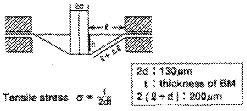
m msnihr&ss*** 3.42 * 19*
At" L* - L
Thktotess ·· &W : 15 μΐα, 8M : 4 jtia, : 8 μΤΆ.
Strain 6
[0097] The limitations of the prior study were overcome in the present disclosure by the use of a nano indenter. A schematic representation of a nanoindenter is shown in Figure 14. The main shaft (10) of the nanoindenter is mounted in linear bearings so as to allow motion of the shaft along its axis, which is effected by a set of magnetic coils (20). Thus the position of the shaft is determined and controlled by the electric current flowing through the magnetic coils. The position of the nanoindenter shaft is measured using an electrical capacitance gauge (30). A set of leaf springs (40) of known stiffness deforms when the shaft moves; the force exerted onto the nanoindenter shaft can then be determined from the known deflection and stiffness of the springs. A motorized stage 50 is provided which can move in the x and y-direction to allow for multiple operations of the nanoindentor to form a series of holes in the sample. An indenter tip, of a very hard material, is mounted on the shaft. Typical nanoindenter tips are made of diamond, however tungsten wires can also be employed which are micro-machined to different tip shapes and sizes, as seen in Figures 15a-b. Although two exemplar}' embodiments are shown for
purpose of illustration and not limitation, it will be understood by artisans of ordinary skill that alternative geometries can be provided, as so desired. Sophisticated feedback control systems can then be used to prescribe either the displacement or the force on the indenter shaft as a function of time.
[0098] In one embodiment, the nanoind enter tip is indented into a material. The force and the displacement on the nanoindenter tip are measured during this process. In some embodiments, the material will be a free-standing RWM membrane or a proxy material. The membrane itself deflects globally even as the sharp tip indents locally into the deforming material. Hence, the total measured displacement is the sum of the local and global
displacements. From the measured force-displacement data, various material models can be employed to determine the mechanical properties of the suspended membrane. An example of a force-displacement curve related to indentation into a RWM is in Figure I6a~b. For an ideal linear-elastic membrane, the force increases as the cube of displacement; this behavior can be seen approximately in Figure 16b at the earliest stages of indentation. Then at an indentation depth of about 75 micrometers, the character of the force-displacement curve changes abruptly. This is a signal that the indenter tip has begun to penetrate the membrane locally rather than only to deflect globally the membrane. The post-penetration behavior of the force-displacement response depends upon the details of the shape of the indenter tip, and is one of the degrees of freedom employed in accordance with the disclosed subject matter.
[0099] One of the main requirements for accurate analysis of the force-displacement response of an indented material is to determine accurately the indenter position at which the tip first comes into contact with the membrane. Traditional methods to determine the point of contact rely on measurement of a non-zero force, but the potential for significant error
identifying contact exists due to many different experimental factors. To that end, a dynamic method is employed to determine the point of contact. A linearly varying displacement of the nanoindenter tip with respect to time as it approaches the surface is prescribed, and
superimposed thereupon is the linear motion a sinusoidal variation of displacement with respect to time with amplitude of a few nanometers. The phase lag between the prescribed position and the measured force on the ind enter tip is then monitored. The nanoindenter system is sufficiently sensitive to be able to measure the drag force of the nanoindenter tip as it moves through air. Thus, the force lags the displacement, slightly even in air. However when the nanoindenter tip comes into contact with the surface of the material of interest, there is a sudden increase in the phase lag over the distance of just a few nanometers of displacement. With this method it, is possible to obtain repeatedly a significantly greater precision of the contact position.
[00100] For example, the nanoindenter can be the Agilent G-2QQ. The Agilent G-200 nanoindenter includes a anovision option for contact imaging, a Lateral Force Measurement module, a High Load Option, an XP indenter head (force resolution of 50 niN, maximum force of 500 mN, displacement resolution of 0.01 nm, maximum indentation depth 500 μιη) with Continuous Stiffness Monitoring capability, Dynamic Contact Module (DCM) indenter head (force resolution 1 mN, maximum force 10 mN, atomic scale displacement resolution, maximum indentation depth of 15 μτη) with Continuous Stiffness Monitoring capability, and TesfWorks 4 Explorer Level software package to control the system and to record the output. The mounting fixture for the nanoindenter tips is versatile and robust, which is compatible with the wide range of different, nanoindenter tips (both in shape as well as surface roughness) which can be employed in accordance with the present disclosure. Exemplary experiments have used custom-made tungsten tips shown in Figure 15a-b. The high Young's modulus of the tungsten
(i.e. 411 GPa) makes it possible to ignore the deformation within the nanoindenter tip as there is little to no contribution of the tip deformation to the measurement. However the deformation within the tip is not negligible for the silicon array of micro-needles employed in accordance with the disclosed subject matter, which requires extensive modeling to ensure the indenter tip acts as intended.
[00101] The disclosed subject matter will present numerous advantages over conventional inner ear treatment devices and methods, and will provide numerous benefits to patients. For purpose of illustration, and not limitation, some specific aims of the presently disclosed subject matter are set forth below.
[00102] Aim 1. Characterization of mechanical properties of the RWM usin the
nanoindenter.
[00103] Rational: Without biophysical modeling of the interaction between the RWM and micro-needle array, the design of the micro-needle and its penetration of the RWM is heuristic rather than reductive. anoindentation is a robust experimental tool to effect micro-needle penetration of RWM. The reliability of the micro-needle array is quantified as a factor of safety (FS) that is defined by the ratio of the load that causes the failure of a micro-needle divided by the force that is required to penetrate the RWM. in accordance with the disclosed subject matter, the indentation load and displacement at rupture of the RW is measured. The Young's modulus and strength at perforation is estimated using the ABAQUS finite element modeling (FEM) by comparing the simulated force and the deflection required for a micro-needle array to cause rupture of the membrane to the experiments.
[00104] Methods: Two tungsten probes, one with tip curvature of 0,4 μηι and the other a 20 μηι flat probe, are employed initially in nanoindentation (Figure 15a-b). A Guinea pig cochlea is extracted and kept in a cold saline solution until placed in the nanoindentation chamber. The cochlea is placed in the chamber with the RWM facing upward. The contact of the tip on the RWM is confirmed either manually when the load rate steadily exceeded 0 N/ni with an indentation speed of 1 μιη/sec, or via the phase lag method. The completion of the rupture is determined by the characteristic behavior of the force-displacement curve. The rupture diameter is confirmed visually with a lOx microscope objective mounted on the nanomdenter.
[00105] The results obtained with these methods are shown in Figure 16a-b. The force- displacement curve obtained with 20 μτη probe shows more than 20 mN load and 200 μιη displacement (Fig. 16a) at, the time of penetration. The diameter of the rapture was about, 20 to 50 μη in diameter. The 0.4 μηι tip penetrated the RWM at less than a 10 mN load and 80 μηι displacement (Fig. 16b). The indentation was stopped after the indenter traveled an addition 100 μτη through the perforated RWM to ensure a visually detectable perforation. The resulting hole of less than 10 μηι diameter was visible under the microscope.
[00106] To estimate the Young's modulus and strength at perforation, the rupture process will be modeled numerically using ABAQUS. For a guinea pig, the RW rupture is modeled as being axisymmetric with a 1.2 mm diameter and a ΙΟμιη thickness assuming, initially, an isotropic, linear-elastic material; other material models such as hyperelastic models, is implemented as necessary. The model employs pinned boundary conditions along the rim and indenter is modeled, initially, as a rigid body of the shape of the indenter tip that displaces the RWM; the elastic properties of the indenter tip is taken into account as necessary. The relevant mechanical properties (e.g. Young's modulus) is determined by fitting the simulated force-
displacement results to the experimental data. The strength at perforation is estimated from the maximum von Mises stress which is an invariant measure of the stress.
[00107] Based upon preliminary studies, the Young's modulus was estimated to he about 100 MPa, which is quite high, but this can indicate a high collagen density in the RWM. The calculated Von Mises stress in the RWM under the indenter is shown in Figure 17; the high stress area (A) indicates that the rupture likely initiated around the edge of the tungsten probe. Results of Figure 18 shows the force at perforation of a guinea pig RWM for the two tungsten tips in Figure ! 5a-b. In addition, preliminary ABAQUS calculations for the force at perforation for a flat indenter as a function of diameter are shown in Figure 18, assuming perforation occurs at a critical von Mises stress. These results suggest that, the load is proportional to the radius of the probe tip.
[00108] Figure 18 shows a reliability estimate of the micro-needles that compares the buckling force of a nanoindenter tip to the force at perforation, the ratio of which is the safety factor, FS. These results suggest that by reducing the tip diameter below 1 μπι, the rupture force can be reduced down to 10 iriN. Thus, a 10 fxm and 20 μτη radius needle will have FS of 2 and 36 respectively, in this study, the buckling force is calculated based upon modeling the actual geometry of the indenter tips fabricated and employed in the experiments. The pertinent boundary conditions are to fix one side against displacement and to allow the other end freedom to displace and rotate. Then a buckling analysis is performed to determine when the nano- needles are expected to fail due to lateral motion (either buckling or bending).
[00109] Furthermore, the penetration of the membrane with micro-needle array is modeled to estimate the FS due to the two failure modes (i.e., buckling and bending) by calculating the loading force and bending moment on each needle. A preliminary result indicates that the ability
to effect rupture of the RWM with the same load on each micro-needle is improved by judicious positioning of the needle on the RWM surface.
[00110] Experimental characterization of at least twelve different guinea pig RWMs was performed. One mode of experiment is the perforation experiments. A second mode of experiment is to place the RWM on a flat hard (e.g. silica) surface in a saline solution bath and perform flat punch indentation. One advantage of the second mode is that the experiment can be repeated several times on each R WM without major modification of the mechanical response of the system. Additionally, Student's t-test or AN OVA, as appropriate, can be performed on the results.
[00111] Figure 19 depicts an exemplary nanoindentor which was configured as a 20μηι tapered needle and employed to form a series of perforations in the RWM, as shown in Figure 20. As the perforations are disposed closer to each other, the structural integrity of the membrane becomes compromised which can lead to undesired tearing or elongation of the perforation. Accordingly, in the exemplary embodiment shown in Figure 19, the midpoint of each perforation is spaced approximately ΙΟΟμιη apart. Additionally, the depth of penetration of the nanoindentor can affect the perforation size. In this regard, Figure 20 depicts three short stroke perforations and one deep stroke perforation, with the perforations of the short strokes being smaller relative to the deep stroke perforation.
[00112] In accordance with another aspect of the disclosure, the mechanical property characterization of the RWM allows for an understanding of the relationship between the load (of the needle or nanoindentor) and the displacement, into the surface of the membrane. As previously discussed with regard to the shape and contour of the RWM, the negative and positiv e curvatures of the RWM represent a saddle point, as shown in Figure 21. A corresponding graph
of the load vs. displacement is provided in Figure 22 which depicts the expected value (based on a Young's Modulus of 19.4MPa), as compared to the values at the flat portion of the saddle point and concave portion of the saddle point (i.e. proximate the longitudinal ends on the x-axis), [00113] Furthermore, the present disclosure analyzed the load vs. displacement relationship for different size needles. As sho in Figure 23, the load vs. displacement curve is provided for a 20 micron needle as well as a Fine needle. Additionally, a plot of the stress at the point of rupture is provided in Figure 24 (based on a Young's Modulus of 170MPa).
[00114] Aim 2. Based on the mechanical properties of the RWM, design micro-needles for creating inicroperforations in the RWM.
[00115] Design based on the nanoindentation results: The force and displacement indicate that to produce a 20 μπι diameter hole the needle should withstand an axial force of at least 10 mN. Also, a 100 μηι length is necessary to ensure the substrate of the micro-needle does not touch the RW . To maintain a FS of 10 against budding failure, a 10 μτη diameter 100 μτη long Si column with tip size of 2 μτη is used.
[00116] In an exemplary embodiment, the fabrication process of the micro-needles is by isotropic etching combined with cryogenic processes that produce a taper. Figures 5 and 7-8 shows a single φΐθ μηι micro-needle in addition to a 10 x 10 array of cp20 μηι micro-needles. The fabrication parameters are optimized to produce the designed shape based upon fabrication processes shown schematically in Figure 25. The micro-needles (with 10, 20, 50 μηι diameter) are patterned by a Chromium mask on glass with (DWL 2000, Heidelberg instruments) in 2- dimensional arrays. These patterns are transferred to 100 run chromium thin films of on the Si
wafer by optical lithography using a mask aligner (MA/BA6, SUSS MicroTec) followed by physical vapor deposition (PVD75, Kurt J, Lesker) and lift off with solvent (Remover 1165, Microposit). The chromium mask protects the Si from etching to allow formation of the microneedles. The tip diameter is formed by isotropic Si etching with Sf y'O:? gas in a Reactive Ion Etcher (R1E) (Trion Phantom III). The shaft is created by anisotropic Si etching with cryogenic SFfy'Ou process in a Deep Reactive Ion Etcher (Oxford Plasma Lab). The chromium mask is removed by wet etching. The fabricated silicon wafer is diced to have a 1 mm square stamp with micro-needle array. [00117] Aim 3. Analyze the different desi gns of micro-needles and their ability to create mi cro-perf rati n and to characterize the size and nature of these perforations.
[00118] Aim 3,1 Introduction of mi cro-perforation and reliability evaluati on. [00119] Rational: The needle array of the present disclosure allows for simultaneous perforations of RWM. The physical interaction of the needle array and RWM can be predicted from the single tungsten needle penetration with some degree of uncertainty. The likelihood of failure of the micro-needles must be clarified in order to optimize the micro-needle array design and the penetration method. The load that causes buckling and bending failure of the micro- needle can be determined. By indenting the fabricated micro-needle on the well-defined hard substrate as well as the RWM in situ, the reliability of the micro-needle array is assured,
[00120] Methods: The reliability of the exemplary micro-needle is tested by the nanoindenter. The micro-needle array is attached to a nanoindenter tip fixture. First, the
budding and bending force is determined for an individual micro-needle by pressing the microneedle onto a block of fused silica (E = 72 GPa, H = 9 GPa) and (E= 0,5 MPa, H = 7.1 MPa). The buckling is characterized by vertical loading and the bending is characterized with the lateral forces.
[00121] The fabricated micro-needle array is mounted onto the nanoindentater to penetrate a guinea pig RWM. The specimen and the mechanical interaction characterization are as described above in Aim 1. The micro-needle array is lowered to the membrane and penetration is performed. The diameter of the micro-needle is varied by the fabrication process to obtain an FS of 1. The number of micro-needl e in the array varies from 1 to 2 x 2 to 10 x 10 to quantify the effects that arise from the geometry and the number of needles. The mode of damage to the micro-needle is confirmed by optical microscope and scanning electron microscope. Buckling or bending are the primary causes of the failure. Numerical models in ABAQUS are optimized to examine the significant mechanical characteristics that lead to failure. At the same time, to develop a method to safely introduce micro-perforations during in vivo experiments, the contact detection criteria and subsequent loading variables until the RWM perforation are determmed.
[00122] After the first needles in the array penetrate the membrane, friction between the needles and the membrane may serve to reduce the efficacy of the penetration by the remaining needles. The membrane deflection may induce lateral forces on the needle by friction resulting in bending failure of the needle.
[00123] Aim 3.2 Micro-perforation diameter determination.
[00124] Rational: The shape of the hole generated by the micro-needies determines the diffusive permeability improvement, the fluid dynamic leakage prevention and the level of
damage to the cellular architecture. Thus, control over the hole size by the tuning the needle shape and subsequent required applied force, displacement and indentation rate by the nanoindenter is desirable. Additionally, the inelastic deformation that induces the hole can be characterized.
[00125] Methods: The perforated round window membrane is stained with hematoxylin and eosin after fixation. Using a high numerical aperture lens, the cross section of the hole is scanned vertically. The 3-D structure of the perforation is examined.
[00126] The size of the RVVM can be different from the micro-needle diameter. For example, a 20 μηι tungsten tip causes a bigger hole than the tip diameter. In accordance with an aspect of the disclosed subject matter, an understanding of the inelastic and elastic properties of the RVVM in order to determine the underlying deformation mechanisms and control the perforation diameter is provided. Even though there is a significant difference between the mechanical and cellular architectural of the human and guinea pig RVVMs, this development system can be applied to the human RWM model smoothly. The micro fabrication batch processing allows several different geometries to be fabricated at a time to accelerate development.
[00127] Aim. 4. In vitro characterization of the changes in permeability associated with micro-needles.
[00128] Rational: The permeability improvement of the RWM is quantified in vitro using confocal microscopy. Guinea pig cochleae is used as a model system because of the relatively ample number of studies. In vivo experiments impose difficulties to address specifically the diffusive permeability improvement by the micro-perforation. Agar is used to exclude
convection and study specifically diffusive transport of molecules. Additionally, a Confocal microscope is employed to quantify the movement of fluorescent molecules via diffusion in the micro-perforation with sub-micron resolution.
[00129] Aim 4. ί Macroscopic permeability experiment.
[00130] To quantify the permeability, the diffusion of fluorescent dyes through the perforated RWM is studied. Rhodamine B is used as a model molecule because its molecular size and diffusion coefficient are close to the two therapeutic reagents.
[00131] Aim 4.2 Microscopic diffusion study .
[00132] To study the diffusion through the micropore in detail, confocal microscopy is performed. The agar diffusion channel is again used. In one embodiment, the focal plane is fixed to include the pores in the plane.
[00133] Methods: A perforated membrane is placed on a 3% agar with thickness of 200 μηι sliced with a vibratome. With reference to Figure 26, the excised RWM (100) is placed on an agar (slice A, 200). Another agar (slice B, 202) is placed atop the RWM. Aqueous discontinuities such as bubbles are eliminated. Rhodamine B (lmM) is poured on the bottom agar. By diffusion, the Rhodamine B will diffuse to agar B through the RWM. The agar on the top is removed and the amount of the Rhodamine B in the agar is quantified with a fluorescent microscope (Zeiss Axiolab). Using a confocal microscope (Leica, TCS SP5 II), horizontal planes in the round window membrane are monitored to determine the flux of the fluorescent dye, based upon the increase of intensity of the fluorescent dye. The permeability can be calculated from the amount of flux.
[00134] A Franz cell was employed to analyze the diffusion characteristics of the RVVM, as shown in Figure 28. Three different tests specimens were analyzed: i) a perforated RVVM leak: ii) a 10 μηι porous filter; and iii) an intact RWM. The results are shown in Figure 29 which demonstrate that the perforated RWM has a significant reduction in diffusion time as compared to the 10 μιη porous filter; and iii) an intact RVVM.
[00135] Aim 4.3 In situ diffusion study,
[00136] In accordance with another aspect of the disclosure, the permeation of fluorescent dye through the mieroperforation into the scala tympani in situ with cochlea bone is examined with confocal microscopy.
[00137] Methods: A guinea pig cochlea is extracted and the RWM is exposed. The cochlea is fixed on a glass plate to make the RWM face vertically. The micro perforation is introduced by the developed methods with the micro-needle array, as described above. Under the confocal microscope, the focus plane is set just below the R WM. 10 μΐ, of 0.1 mM
Rhodamine B in perilymph solution is poured on the RVVM. The flux of Rhodamine B can be measured and the permeability calculated.
[00138] This procedure can quantify the improvement of the permeability of the RVVM of the Guinea Pig. The permeability of the perilymph solution is estimated from the diameter of the pore. The confocal microscopy itself can be a better option to determine the 3-D structure. However, in some embodiments, the fluorescent dye may be bound and immobilized to the membrane.
[00139] Aim 5. Characterization of the anatomic and functional consequences of using micro-needle array to create RWM perforations and to assess the ability of micro-needles to reliably deliver therapeutic materials into the cochlea using guinea pig as an animal model.
[00140] Rationale, The successful completion of above specific aims 1 -4 aids in defining the optimal design of micro-needle array for testing in vivo. The guinea pig was chosen as the animal model because of ease of surgical access to the RWM. In this aim, perforations are created with the micro-needle array and characterize the length of time they stay patent, their effect of hearing, and their ability to enhance diffusion across the RWM. [00141] Aim 5.1. Define the histologic and functional consequences of micro-needle array introduced micro-perforations in the RWM.
[00142] Based on results from larger perforations, the healing process can be expected to close the micro-perforation of the RWM within 4-8 days. Thus, to determine the time course over which the micro-perforations close, the RWM are harvested immediately after the procedure, at 6 hours, 24 hours and at one week and two weeks. Additionally, tests for auditor}' function with auditor}' brainstem response testing (ABR) and distortion product otoacoustic emissions (DPOAEs) can be performed immediately after surgery, and then at 2, 7, 14, and 28 days after surgery.
[00143] Animal Surgery: Animals are anesthetized with a combination of intra-muscular ketamine (50 mg/kg) and the analgesic xylazine (9 mg/kg), and administered antibiotic prophylaxis using 4 mg of trimethoprim and 20 mg of sulfadiazine. Both RWMs are surgically accessed in all animals. A post-auricular incision is introduced with a few mm diameter opening of the bulla. Following a minimal bone removal in that area, the round window membrane is
directly visualized. A stereotactically fixed stainless tube is introduced into the incision vertically toward the RWM. The micro needle loading surgical apparatus is introduced through the stainless tube. The RWM perforations are produced with the apparatus using the optimized variables from the in situ procedures.
[00144] Tissue Processing: The animals are sacrificed with an intraperitoneal overdose of sodium pentobarbital (250 mg/kg) followed by bilateral thoracotomy. At the time of sacrifice, the animals are perfusion-fixed with a solution of 4.0% paraformaldehyde in 0.1 M phosphate buffer, pH 7.4. Temporal bones are harvested from both sides of the head. Each bulla are opened using rongeurs to expose the cochlea. The stapes are removed and the cochlea fixed by perfusion of 4.0% paraformaldehyde through the round window. The cochlea is then removed from the remaining temporal bone and immersed in 4.0% paraformaldehyde overnight at 4°C. After complete fixation, specimens are decalcified in 0.2M EDTA/IX PBS/4.0%
paraformaldehyde for 2■■ 3 weeks with at least three solution changes. Following
decalcification, the specimens are placed in 0.9% saline, dehydrated through a graded alcohol series and then equilibrated in xylenes. Specimens are embedded in paraffin and sectioned at, 6 - 8 μιη on a microtome (Leica RM2035) for histology and immunohistochemistry.
[00145] Two cochleae from each sample group and time point are embedded in plastic for morphological evaluation of RWM. Briefly, the harvested cochleae is fixed in 2.5%
glutaraldehyde in 0.1 M phosphate buffer. After 24 hours, the cochleae is rinsed with phosphate buffer, postfix ed with 1 % osmium tetroxide, and then dehydrated in a graded series of ethanol, transferred to propyleneoxide, and embedded in plastic (Agar 100 Resin kit, Agar Scientific).
[00146] After polymerization and removing the bone adjacent to the RWM, the area of round window niche with the RWM is re-embedded on a blank block of Agar 100 to allow
sectioning perpendicularly to the membrane. The specimens are sectioned at 2.5 μηι thickness using a microtome (LKB Ultramicrotome system 2128 Ultrotome). Thin sections are mounted on glass slides and stained with 0.1% toluidine blue. The RWM thickness is measured using a light microscope (Zeiss Axiolab) equipped with a digital camera (Altra 20 soft imaging system, Olympus) and image analysis software (Cell, Olympus). Measurement of three sections of each RWM is made at the mid portion of each membrane, and the mean value is calculated. For electron microscopy, ultra thin sections are obtained, mounted on copper grids, and stained with uranyl acetate and lead citrate. Grids are examined with a Phillips CM12 Transmission Electron Microscope and photographed with a I k x Ik Gatan CCD Camera.
[00147] Histology and m unohistochemistr : The cochlear paraffin sections for immuriochemistry are prepared as previously described. Briefly, the paraffin-embedded cochlear sections is dewaxed, blocked with 10% NHS, 0,1 % Tween 20 in PBS and then hybridized overnight with the relevant primary antibody. Presence of cell-mediated immune response is charaeterized using antibodies against the guinea pig T4 lymphocytes (anti-CD45 antibody, clone no. lH-1) and macrophages (anti-Ll antibodies, clone no. MAC387). Both of these antibodies are commercially available through Serotec Inc, Raleigh, NCI The hybridized sections is then be processed as described above.
[00148] Auditory Brainstem Response (ABR) Testing: Following administration of anesthesia, responses are recorded from silver wire electrodes inserted through the skin at the vertex (negative), ipsilateral mastoid (positive) and contralateral mastoid (ground). The scalp- recorded potentials are amplified and sampled at a rate of 10 kHz by an analogue to digital converter using Tucker-Davis software. The clicks or tones (4, 8, 16 and 32 KHz) are presented at a rate of 33 per second and the responses averaged over 500 trials. The ABR threshold to a
broadband (click) stimulus are established for both ears. At near-threshold stimulus levels, recordings are repeated to test the consistency of wave identification. For both ears, the ABR threshold at each frequency is defined, as the stimulus needed to produce a visual detection of at least one of the waves observed in response to a broadband click stimulus. Data is statistically evaluated by Student's t-test and by ANOVA with Tukey's or Newman- euls post-hoc test.
[00149] Qtoacoustie Emission Testing: Following administration of anesthesia, Distortion
Product Otoacoustic Emissions (DPOAEs) at, 2fi-f2 is elicited from both ears using a Tucker Davis Technologies (Gainesville, FL) System II. Two equivalent level
 primary signals (fj and f2), with
 are generated and test frequencies will range from 2 to 18 kHz. The primary tones produced by two separate speakers (modified Super Tweeter 40- 1310B Tandy Corporation, Fort Worth, TX) is introduced into the animal's sealed ear canal through an insert earphone speculum. DPOAE recordings is made with a low-noise microphone (Etymotic Research, ER 1 (©Detection threshold and supra-threshold measures in the form of input/output (I/O) functions are obtained by decreasing the primary tones from 85 to 25 dB sound pressure level (SPL), in 5-dB steps. An emitted response is identified as positive if the DPOAE at 2fj - f2 is 3 dB above the noise floor level. Statistical significance of differences between the control and experimental cochlea is determined using Fisher's least square difference and Scheffe's F-test.
[00150] Aim 5.2 To characterize the diffusion of therapeutic reagents through micro- needle array introduced micro-perforations in the RWM.
[00151 ] Rational: The permeability of gentamicin through the RWM of Guinea pig is determined in vivo. An analysis of how the introduction of the micro-perforations impacts or enhances permeability is provided. The amount of the gentamicin delivered into the scala
tympani is determined and the ratio between the amount collected and administered is quantified as deliver}? efficacy. In some embodiments, the effect of the artificial modification to the endogenous permeability of the RWM lasts for a few hours. Thus, this acute procedure is suitable to show the permeability improvement and independency before the endogenous healing process affects the perforation.
[00152] Methods: Application of drug to RWM. Immediately after the introduction of micro perforation, gentamicin (Refobacin 40 mg/mL, Merck, Darmstadt, Germany) is applied in a continuous drip to the RWM from a pipette placed close to the bony lip of the round window (RW) niche for 1 , 2, and 3 hours. The rate of drug irrigation is 5 p.L/min in the 30- minute experiments, 4 μΕ/min in the 2 hour experiments, and 5 μ,Ε/ηπη reduced to 2 μΕ/'τηίη after the first hour in the 3 hour experiments. The intracochlear fluid is sampled from a small opening made in the apical turn of the cochlea. To collect all of the fluid without, any loss to the middle ear, a cup made of a two-part silicone adhesive (Kwik-Cast, World Precision Instruments, Sarasota, FL) is constructed around a small portion of exposed apex site at the apex. To sample effusate, an incision is made in the silicone cap with a pick. Perilymph solution emerging from the incision is collected sequentially 10 times with glass capillary tubes. Each collected sample is approximately 1 μΕ.
[00153] Quantification of gentamicin. Each sample is diluted with 120 μΐ, of Abbott Labs
IVD 9519 dilution buffer, Gentamicin is quantified with a fluorescence-polarization- immunoassay (TDX SEX Analyzer, Abbot, Abbott Park, IE). The permeability of the RWM is determined using the FEM software obtained at http://oto.wustl.edu/cochlea/. The concentration of gentamicin is simulated and the permeability is changed until the calculated concentrations best fits with the 10 samples from each procedure.
[00154] While the disclosed subject matter is described herein in terms of certain preferred embodiments, those skilled in the art will recognize that various modifications and
improvements may be made to the disclosed subject matter without departing from the scope thereof. For example, while the exemplary embodiment(s) disclosed above are directed to cochlear applications, the disclosed subject matter could also be configured for use with the eye, middle ear, brain or other thin membranes within the body.
[00155] Moreover, although individual features of one embodiment of the disclosed subject matter may be discussed herein or shown in the drawings of the one embodiment and not in other embodiments, it should be apparent that individual features of one embodiment may be combined with one or more features of another embodiment or features from a plurality of embodiments.
[00156] In addition to the specific embodiments claimed below, the disclosed subject matter is also direc ted to other embodiments having any other possible combination of the dependent features claimed below and those disclosed above. As such, the particular features presented in the dependent claims and disclosed above can be combined with each other in other manners within the scope of the disclosed subject matter such that the disclosed subject matter should be recognized as also specifically directed to other embodiments having any other possible combinations. Thus, the foregoing description of specific embodiments of the disclosed subject matter has been presented for purposes of illustration and description. It is not intended to be exhaustive or to limit the disclosed subject matter to those embodiments disclosed.
[00157] It will be apparent to those skilled in the art that various modifications and variations can be made in the method and system of the disclosed subject matter without departing from the spirit or scope of the disclosed subject matter. Thus, it is intended that the
disclosed subject matter include modifications and variations that are within the scope of the appended claims and their equivalents.
Claims
1 . A medical device capable of creating temporary perforations in the round window membrane of an inner ear, comprising:
a plurality of micro-needles, each micro-needle having a diameter of about 20 microns, wherein the plurality of micro-needles are coupled to a base configured to engage a driver device.
2. The medical de vice of claim 1 , wherein the plurality of micro-needles are arranged in an array,
3. The medical de vice of claim 1 , wherein the micro-needles are made of si licon.
4. The medical device of claim 1 , wherein at least one of the plurality of microneedles is hollow.
5. The medical device of claim 4, wherein the hollow micro-needles include a lumen for delivering a therapeutic agent into the perforations.
6. The medical device of claim 1 , wherein at least one of the plurality of microneedles is formed with a solid cross-section.
7. The medical device of claim 6, wherein the solid micro-needles include a therapeutic agent disposed on an exterior surface.
8. The medical device of claim 1 , wherein at least one of the plurality of micro- needles includes a tapered tip of about 0.5 microns.
9. The medical device of claim 8, wherein the tapered tip is configured as a gradual taper.
10, The medical device of claim 8, wherein the tapered tip is configured as a stepped taper.
1 1. A system for delivering therapeutic agent to the inner ear of a subject comprising: an instrument for accessing the round window membrane;
a plurality of micro-needles, each micro-needle having a diameter of about 20 microns, each micro-needle having sufficient rigidity to perforate the round window membrane; and
a driver,
wherein the plurality of micro-needles is coupled to the driver.
12. The system of claim 1 1 , wherein the system is modular in which the instrument for accessing the round window membrane, plurality of micro-needles, and driver are separate components.
13. The system of claim 1 1 , wherein the system is disposable.
14. The system of claim 1 1 , wherein at least one of the plurality of micro-needles includes a hollow lumen.
15. The system of claim 14, further comprising a reservoir to house a therapeutic agent.
16. The system of claim 15, further comprising a dispensing mechanism for delivering therapeutic agent from the reservoir to the micro-needle.
17. The system of claim 14, further comprising a suction mechanism for aspirating the round window membrane.
18. The system of claim 16, wherein at least one of the micro-needles is removed from the round window membrane perforation prior to dispensing the therapeutic agent.
19, The system of claim 1 1 , wherein the therapeutic agent has a molecular size of 3 μιη or larger.
20. A method of delivering a therapeutic agent into the cochlea comprising:
determining the shape of at least one micro-needle;
determining the amount of force to be applied to the at least one micro-needle for perforating the round window membrane;
determining the displacement and indentation rate of the at least one microneedle;
positioning the at least one micro-needle proximate the round window membrane; perforating the round window membrane;
dispensing a therapeutic agent at said perforation(s).
Priority Applications (3)
| Application Number | Priority Date | Filing Date | Title |
|---|---|---|---|
| EP13862239.4A EP2931196A4 (en) | 2012-12-14 | 2013-12-13 | System and method to locally deliver therapeutic agent to inner ear |
| CA2932540A CA2932540A1 (en) | 2012-12-14 | 2013-12-13 | System and method to locally deliver therapeutic agent to inner ear |
| US14/667,322 US10821276B2 (en) | 2012-12-14 | 2015-03-24 | System and method to locally deliver therapeutic agent to inner ear |
Applications Claiming Priority (4)
| Application Number | Priority Date | Filing Date | Title |
|---|---|---|---|
| US201261737285P | 2012-12-14 | 2012-12-14 | |
| US61/737,285 | 2012-12-14 | ||
| US201361833849P | 2013-06-11 | 2013-06-11 | |
| US61/833,849 | 2013-06-11 |
Related Child Applications (1)
| Application Number | Title | Priority Date | Filing Date |
|---|---|---|---|
| US14/667,322 Continuation-In-Part US10821276B2 (en) | 2012-12-14 | 2015-03-24 | System and method to locally deliver therapeutic agent to inner ear |
Publications (1)
| Publication Number | Publication Date |
|---|---|
| WO2014093875A1 true WO2014093875A1 (en) | 2014-06-19 |
Family
ID=50935005
Family Applications (1)
| Application Number | Title | Priority Date | Filing Date |
|---|---|---|---|
| PCT/US2013/075105 WO2014093875A1 (en) | 2012-12-14 | 2013-12-13 | System and method to locally deliver therapeutic agent to inner ear |
Country Status (3)
| Country | Link |
|---|---|
| EP (1) | EP2931196A4 (en) |
| CA (1) | CA2932540A1 (en) |
| WO (1) | WO2014093875A1 (en) |
Cited By (5)
| Publication number | Priority date | Publication date | Assignee | Title |
|---|---|---|---|---|
| US20140364947A1 (en) * | 2011-08-31 | 2014-12-11 | Mark Matthew Scheurer | Middle ear prosthesis having discrete projections for purposes of ossicular attachment |
| EP3160406A4 (en) * | 2014-06-27 | 2018-02-21 | The Trustees of Columbia University in the City of New York | Apparatus for perforation and aspiration of inner ear |
| US11213430B2 (en) | 2016-05-26 | 2022-01-04 | Cochlear Limited | Inner ear plug |
| WO2023014342A1 (en) * | 2021-08-02 | 2023-02-09 | Restorear Devices, Llc | Methods and devices for applying hypothermic therapy to a human auditory system |
| EP4093355A4 (en) * | 2020-01-24 | 2024-02-21 | Spiral Therapeutics Inc | Systems and methods for treating hearing loss |
Citations (6)
| Publication number | Priority date | Publication date | Assignee | Title |
|---|---|---|---|---|
| US20050209565A1 (en) * | 1999-06-09 | 2005-09-22 | The Procter & Gamble Company | Intracutaneous microneedle array apparatus |
| US20060264897A1 (en) * | 2005-01-24 | 2006-11-23 | Neurosystec Corporation | Apparatus and method for delivering therapeutic and/or other agents to the inner ear and to other tissues |
| EP0989868B1 (en) * | 1997-06-13 | 2009-05-13 | Durect Corporation | Inner ear fluid transfer and diagnostic system |
| US20110301681A1 (en) * | 2006-09-29 | 2011-12-08 | Frank Risi | Electrode assembly for a stimulating medical device |
| US20120021416A1 (en) * | 2010-07-21 | 2012-01-26 | Saint Louis University | Biolayer interferometry measurement of biological targets |
| US20120245419A1 (en) * | 2004-04-21 | 2012-09-27 | Acclarent, Inc. | Devices, Systems and Methods For Diagnosing and Treating Sinusitis and Other Disorders of the Ears, Nose and/or Throat |
Family Cites Families (5)
| Publication number | Priority date | Publication date | Assignee | Title |
|---|---|---|---|---|
| US8197461B1 (en) * | 1998-12-04 | 2012-06-12 | Durect Corporation | Controlled release system for delivering therapeutic agents into the inner ear |
| US20070185432A1 (en) * | 2005-09-19 | 2007-08-09 | Transport Pharmaceuticals, Inc. | Electrokinetic system and method for delivering methotrexate |
| EP1928539A1 (en) * | 2005-09-30 | 2008-06-11 | Tti Ellebeau, Inc. | Functionalized microneedles transdermal drug delivery systems, devices, and methods |
| US20080065002A1 (en) * | 2006-09-07 | 2008-03-13 | Neurosystec Corporation | Catheter for Localized Drug Delivery and/or Electrical Stimulation |
| US20110306853A1 (en) * | 2010-03-19 | 2011-12-15 | Michael Darryl Black | Body fluid sampling/fluid delivery device |
-
2013
- 2013-12-13 CA CA2932540A patent/CA2932540A1/en not_active Abandoned
- 2013-12-13 EP EP13862239.4A patent/EP2931196A4/en not_active Withdrawn
- 2013-12-13 WO PCT/US2013/075105 patent/WO2014093875A1/en active Application Filing
Patent Citations (6)
| Publication number | Priority date | Publication date | Assignee | Title |
|---|---|---|---|---|
| EP0989868B1 (en) * | 1997-06-13 | 2009-05-13 | Durect Corporation | Inner ear fluid transfer and diagnostic system |
| US20050209565A1 (en) * | 1999-06-09 | 2005-09-22 | The Procter & Gamble Company | Intracutaneous microneedle array apparatus |
| US20120245419A1 (en) * | 2004-04-21 | 2012-09-27 | Acclarent, Inc. | Devices, Systems and Methods For Diagnosing and Treating Sinusitis and Other Disorders of the Ears, Nose and/or Throat |
| US20060264897A1 (en) * | 2005-01-24 | 2006-11-23 | Neurosystec Corporation | Apparatus and method for delivering therapeutic and/or other agents to the inner ear and to other tissues |
| US20110301681A1 (en) * | 2006-09-29 | 2011-12-08 | Frank Risi | Electrode assembly for a stimulating medical device |
| US20120021416A1 (en) * | 2010-07-21 | 2012-01-26 | Saint Louis University | Biolayer interferometry measurement of biological targets |
Non-Patent Citations (3)
| Title |
|---|
| GEERLIGS, M ET AL.: "ln Vitro Indentation To Determine The Mechanical Properties Of Epidermis.", JOURNAL OF BIOMECHANICS., vol. 44, no. 6, 7 April 2011 (2011-04-07), pages 1178, XP055263265 * |
| NGUYEN, Y ET AL.: "Cochlear Implant Insertion Forces In Microdissected Human Cochlea To Evaluate A Prototype Array .", AUDIOLOGY AND NEUROTOLOGY., vol. 17, 30 May 2012 (2012-05-30), pages 297, XP008179775 * |
| See also references of EP2931196A4 * |
Cited By (6)
| Publication number | Priority date | Publication date | Assignee | Title |
|---|---|---|---|---|
| US20140364947A1 (en) * | 2011-08-31 | 2014-12-11 | Mark Matthew Scheurer | Middle ear prosthesis having discrete projections for purposes of ossicular attachment |
| US9326849B2 (en) * | 2011-08-31 | 2016-05-03 | Mark Matthew Scheurer | Middle ear prosthesis having discrete projections for purposes of ossicular attachment |
| EP3160406A4 (en) * | 2014-06-27 | 2018-02-21 | The Trustees of Columbia University in the City of New York | Apparatus for perforation and aspiration of inner ear |
| US11213430B2 (en) | 2016-05-26 | 2022-01-04 | Cochlear Limited | Inner ear plug |
| EP4093355A4 (en) * | 2020-01-24 | 2024-02-21 | Spiral Therapeutics Inc | Systems and methods for treating hearing loss |
| WO2023014342A1 (en) * | 2021-08-02 | 2023-02-09 | Restorear Devices, Llc | Methods and devices for applying hypothermic therapy to a human auditory system |
Also Published As
| Publication number | Publication date |
|---|---|
| EP2931196A1 (en) | 2015-10-21 |
| EP2931196A4 (en) | 2016-07-13 |
| CA2932540A1 (en) | 2014-06-19 |
Similar Documents
| Publication | Publication Date | Title |
|---|---|---|
| US10821276B2 (en) | System and method to locally deliver therapeutic agent to inner ear | |
| Cárcamo-Martínez et al. | Hollow microneedles: A perspective in biomedical applications | |
| Lutton et al. | Microneedle characterisation: the need for universal acceptance criteria and GMP specifications when moving towards commercialisation | |
| EP2931196A1 (en) | System and method to locally deliver therapeutic agent to inner ear | |
| Aksit et al. | In-vitro perforation of the round window membrane via direct 3-D printed microneedles | |
| Kolluru et al. | Recruitment and collection of dermal interstitial fluid using a microneedle patch | |
| Kozai et al. | Reduction of neurovascular damage resulting from microelectrode insertion into the cerebral cortex using in vivo two-photon mapping | |
| Kozai et al. | In vivo two-photon microscopy reveals immediate microglial reaction to implantation of microelectrode through extension of processes | |
| US11844919B2 (en) | Microneedle for local delivery of therapeutic agent | |
| Pararas et al. | Microsystems technologies for drug delivery to the inner ear | |
| RU2585159C2 (en) | Device for delivering drug used in rheumatoid arthritis | |
| Aksit et al. | Drug delivery device for the inner ear: ultra-sharp fully metallic microneedles | |
| Salt et al. | Perilymph kinetics of FITC-dextran reveals homeostasis dominated by the cochlear aqueduct and cerebrospinal fluid | |
| Knaack et al. | In vivo characterization of amorphous silicon carbide as a biomaterial for chronic neural interfaces | |
| Tariq et al. | A review on solid microneedles for biomedical applications | |
| Coffey et al. | Dynamic application of microprojection arrays to skin induces circulating protein extravasation for enhanced biomarker capture and detection | |
| Yu et al. | Anatomical and functional consequences of microneedle perforation of round window membrane | |
| Watanabe et al. | A dual wedge microneedle for sampling of perilymph solution via round window membrane | |
| WO2021050404A1 (en) | Microneedles to deliver therapeutic agent across membranes background of the disclosed subject matter | |
| US20210045925A1 (en) | Apparatuses, systems and methods for perforating and aspirating inner ear | |
| US11413191B2 (en) | Apparatus for perforation and aspiration of inner ear | |
| WO2020214802A1 (en) | Ultra-sharp microneedle | |
| Puri et al. | Characterization of microneedles and microchannels for enhanced transdermal drug delivery | |
| Ibrahim et al. | Surgical trauma after sequential insertion of intracochlear catheters and electrode arrays (a histologic study) | |
| KR101797029B1 (en) | Method of manufacturing of dual structure probe biodevice |
Legal Events
| Date | Code | Title | Description |
|---|---|---|---|
| 121 | Ep: the epo has been informed by wipo that ep was designated in this application |
Ref document number: 13862239 Country of ref document: EP Kind code of ref document: A1 |
|
| WWE | Wipo information: entry into national phase |
Ref document number: 2013862239 Country of ref document: EP |
|
| NENP | Non-entry into the national phase |
Ref country code: DE |
|
| ENP | Entry into the national phase |
Ref document number: 2932540 Country of ref document: CA |