WO2014116502A1 - Methods, systems and devices for treating cardiac arrhythmias - Google Patents
Methods, systems and devices for treating cardiac arrhythmias Download PDFInfo
- Publication number
- WO2014116502A1 WO2014116502A1 PCT/US2014/011912 US2014011912W WO2014116502A1 WO 2014116502 A1 WO2014116502 A1 WO 2014116502A1 US 2014011912 W US2014011912 W US 2014011912W WO 2014116502 A1 WO2014116502 A1 WO 2014116502A1
- Authority
- WO
- WIPO (PCT)
- Prior art keywords
- flow pathway
- constructed
- patient
- clip
- procedure
- Prior art date
Links
- 238000000034 method Methods 0.000 title claims abstract description 419
- 206010003119 arrhythmia Diseases 0.000 title claims abstract description 35
- 230000037361 pathway Effects 0.000 claims abstract description 188
- 230000002792 vascular Effects 0.000 claims abstract description 125
- 210000004369 blood Anatomy 0.000 claims abstract description 17
- 239000008280 blood Substances 0.000 claims abstract description 17
- 206010016717 Fistula Diseases 0.000 claims description 187
- 230000003890 fistula Effects 0.000 claims description 186
- 239000003550 marker Substances 0.000 claims description 76
- 210000001367 artery Anatomy 0.000 claims description 67
- 230000036772 blood pressure Effects 0.000 claims description 60
- 210000003462 vein Anatomy 0.000 claims description 57
- 230000035488 systolic blood pressure Effects 0.000 claims description 54
- 230000035487 diastolic blood pressure Effects 0.000 claims description 45
- 230000000747 cardiac effect Effects 0.000 claims description 43
- 230000009467 reduction Effects 0.000 claims description 42
- 208000037265 diseases, disorders, signs and symptoms Diseases 0.000 claims description 27
- 206010003658 Atrial Fibrillation Diseases 0.000 claims description 24
- DDRJAANPRJIHGJ-UHFFFAOYSA-N creatinine Chemical compound CN1CC(=O)NC1=N DDRJAANPRJIHGJ-UHFFFAOYSA-N 0.000 claims description 24
- 206010020772 Hypertension Diseases 0.000 claims description 23
- 210000002216 heart Anatomy 0.000 claims description 23
- 239000007943 implant Substances 0.000 claims description 23
- 238000005259 measurement Methods 0.000 claims description 23
- 230000004872 arterial blood pressure Effects 0.000 claims description 19
- 238000003384 imaging method Methods 0.000 claims description 19
- 201000002859 sleep apnea Diseases 0.000 claims description 19
- 230000008859 change Effects 0.000 claims description 18
- 210000003734 kidney Anatomy 0.000 claims description 18
- 208000006545 Chronic Obstructive Pulmonary Disease Diseases 0.000 claims description 17
- 238000013153 catheter ablation Methods 0.000 claims description 17
- 238000002679 ablation Methods 0.000 claims description 16
- 230000001746 atrial effect Effects 0.000 claims description 15
- 201000010099 disease Diseases 0.000 claims description 15
- 230000004048 modification Effects 0.000 claims description 15
- 238000012986 modification Methods 0.000 claims description 15
- 230000008660 renal denervation Effects 0.000 claims description 15
- 230000007423 decrease Effects 0.000 claims description 14
- 230000033001 locomotion Effects 0.000 claims description 14
- 230000002889 sympathetic effect Effects 0.000 claims description 14
- 210000001519 tissue Anatomy 0.000 claims description 14
- 230000010339 dilation Effects 0.000 claims description 13
- 206010019280 Heart failures Diseases 0.000 claims description 12
- 230000017531 blood circulation Effects 0.000 claims description 12
- 229940109239 creatinine Drugs 0.000 claims description 12
- 208000035475 disorder Diseases 0.000 claims description 12
- 230000002685 pulmonary effect Effects 0.000 claims description 11
- 210000002966 serum Anatomy 0.000 claims description 10
- 230000002411 adverse Effects 0.000 claims description 9
- QVGXLLKOCUKJST-UHFFFAOYSA-N atomic oxygen Chemical compound [O] QVGXLLKOCUKJST-UHFFFAOYSA-N 0.000 claims description 9
- 230000003247 decreasing effect Effects 0.000 claims description 9
- 238000002405 diagnostic procedure Methods 0.000 claims description 9
- 239000003814 drug Substances 0.000 claims description 9
- 229910001000 nickel titanium Inorganic materials 0.000 claims description 9
- 229910052760 oxygen Inorganic materials 0.000 claims description 9
- 239000001301 oxygen Substances 0.000 claims description 9
- 230000036513 peripheral conductance Effects 0.000 claims description 9
- 238000002604 ultrasonography Methods 0.000 claims description 9
- 206010001052 Acute respiratory distress syndrome Diseases 0.000 claims description 8
- 206010007559 Cardiac failure congestive Diseases 0.000 claims description 8
- 206010021143 Hypoxia Diseases 0.000 claims description 8
- 208000013616 Respiratory Distress Syndrome Diseases 0.000 claims description 8
- 239000000853 adhesive Substances 0.000 claims description 8
- 230000001070 adhesive effect Effects 0.000 claims description 8
- 208000011341 adult acute respiratory distress syndrome Diseases 0.000 claims description 8
- 201000000028 adult respiratory distress syndrome Diseases 0.000 claims description 8
- 210000000709 aorta Anatomy 0.000 claims description 8
- 239000003795 chemical substances by application Substances 0.000 claims description 8
- 230000001010 compromised effect Effects 0.000 claims description 8
- 230000000916 dilatatory effect Effects 0.000 claims description 8
- 229940079593 drug Drugs 0.000 claims description 8
- 230000000694 effects Effects 0.000 claims description 8
- 230000004217 heart function Effects 0.000 claims description 8
- 208000018875 hypoxemia Diseases 0.000 claims description 8
- 239000008177 pharmaceutical agent Substances 0.000 claims description 8
- 208000005069 pulmonary fibrosis Diseases 0.000 claims description 8
- 208000002815 pulmonary hypertension Diseases 0.000 claims description 8
- 230000007704 transition Effects 0.000 claims description 8
- 206010067171 Regurgitation Diseases 0.000 claims description 7
- 230000001684 chronic effect Effects 0.000 claims description 7
- 210000000056 organ Anatomy 0.000 claims description 7
- 230000001225 therapeutic effect Effects 0.000 claims description 7
- 108091008690 chemoreceptors Proteins 0.000 claims description 6
- 238000010276 construction Methods 0.000 claims description 6
- 230000009885 systemic effect Effects 0.000 claims description 6
- 230000006442 vascular tone Effects 0.000 claims description 6
- 230000002861 ventricular Effects 0.000 claims description 6
- 230000006793 arrhythmia Effects 0.000 claims description 5
- 230000035602 clotting Effects 0.000 claims description 5
- 230000006870 function Effects 0.000 claims description 5
- 230000003907 kidney function Effects 0.000 claims description 5
- 239000000463 material Substances 0.000 claims description 5
- 210000003492 pulmonary vein Anatomy 0.000 claims description 5
- 210000002254 renal artery Anatomy 0.000 claims description 5
- 230000029058 respiratory gaseous exchange Effects 0.000 claims description 5
- 229910001285 shape-memory alloy Inorganic materials 0.000 claims description 5
- 210000001631 vena cava inferior Anatomy 0.000 claims description 5
- 108010080379 Fibrin Tissue Adhesive Proteins 0.000 claims description 4
- 230000003872 anastomosis Effects 0.000 claims description 4
- 230000003288 anthiarrhythmic effect Effects 0.000 claims description 4
- 239000003146 anticoagulant agent Substances 0.000 claims description 4
- 208000037849 arterial hypertension Diseases 0.000 claims description 4
- 206010012601 diabetes mellitus Diseases 0.000 claims description 4
- 238000002594 fluoroscopy Methods 0.000 claims description 4
- 210000003709 heart valve Anatomy 0.000 claims description 4
- 230000006872 improvement Effects 0.000 claims description 4
- 206010003662 Atrial flutter Diseases 0.000 claims description 3
- 206010053567 Coagulopathies Diseases 0.000 claims description 3
- 208000001647 Renal Insufficiency Diseases 0.000 claims description 3
- 210000002376 aorta thoracic Anatomy 0.000 claims description 3
- 210000001765 aortic valve Anatomy 0.000 claims description 3
- 210000003157 atrial septum Anatomy 0.000 claims description 3
- 230000008901 benefit Effects 0.000 claims description 3
- 230000000903 blocking effect Effects 0.000 claims description 3
- 210000004556 brain Anatomy 0.000 claims description 3
- UZVHFVZFNXBMQJ-UHFFFAOYSA-N butalbital Chemical compound CC(C)CC1(CC=C)C(=O)NC(=O)NC1=O UZVHFVZFNXBMQJ-UHFFFAOYSA-N 0.000 claims description 3
- 230000002308 calcification Effects 0.000 claims description 3
- 210000003748 coronary sinus Anatomy 0.000 claims description 3
- 230000003205 diastolic effect Effects 0.000 claims description 3
- 210000000245 forearm Anatomy 0.000 claims description 3
- 239000007789 gas Substances 0.000 claims description 3
- 238000002955 isolation Methods 0.000 claims description 3
- 201000006370 kidney failure Diseases 0.000 claims description 3
- 210000005246 left atrium Anatomy 0.000 claims description 3
- 210000005240 left ventricle Anatomy 0.000 claims description 3
- 210000004185 liver Anatomy 0.000 claims description 3
- 210000004115 mitral valve Anatomy 0.000 claims description 3
- 230000001537 neural effect Effects 0.000 claims description 3
- 238000006213 oxygenation reaction Methods 0.000 claims description 3
- 230000036316 preload Effects 0.000 claims description 3
- 208000015658 resistant hypertension Diseases 0.000 claims description 3
- 210000005245 right atrium Anatomy 0.000 claims description 3
- 239000000126 substance Substances 0.000 claims description 3
- 230000000304 vasodilatating effect Effects 0.000 claims description 3
- 206010047302 ventricular tachycardia Diseases 0.000 claims description 3
- 229960004676 antithrombotic agent Drugs 0.000 claims description 2
- 210000005003 heart tissue Anatomy 0.000 claims description 2
- 206010003226 Arteriovenous fistula Diseases 0.000 description 20
- 238000003780 insertion Methods 0.000 description 11
- 230000037431 insertion Effects 0.000 description 11
- 230000000004 hemodynamic effect Effects 0.000 description 9
- 210000003111 iliac vein Anatomy 0.000 description 9
- 230000036593 pulmonary vascular resistance Effects 0.000 description 8
- 210000003090 iliac artery Anatomy 0.000 description 6
- 230000036581 peripheral resistance Effects 0.000 description 6
- 230000002829 reductive effect Effects 0.000 description 5
- 238000002560 therapeutic procedure Methods 0.000 description 5
- 238000004458 analytical method Methods 0.000 description 4
- 238000012360 testing method Methods 0.000 description 4
- 241001573881 Corolla Species 0.000 description 3
- 208000031481 Pathologic Constriction Diseases 0.000 description 3
- 208000006011 Stroke Diseases 0.000 description 3
- 206010048671 Venous stenosis Diseases 0.000 description 3
- 239000003416 antiarrhythmic agent Substances 0.000 description 3
- 238000009530 blood pressure measurement Methods 0.000 description 3
- 229940124630 bronchodilator Drugs 0.000 description 3
- 208000037804 stenosis Diseases 0.000 description 3
- 230000036262 stenosis Effects 0.000 description 3
- 239000005541 ACE inhibitor Substances 0.000 description 2
- 229940127291 Calcium channel antagonist Drugs 0.000 description 2
- 108060006698 EGF receptor Proteins 0.000 description 2
- 206010033557 Palpitations Diseases 0.000 description 2
- 208000007536 Thrombosis Diseases 0.000 description 2
- 230000002159 abnormal effect Effects 0.000 description 2
- 210000003484 anatomy Anatomy 0.000 description 2
- 238000002399 angioplasty Methods 0.000 description 2
- 229940044094 angiotensin-converting-enzyme inhibitor Drugs 0.000 description 2
- 229940127088 antihypertensive drug Drugs 0.000 description 2
- 239000002876 beta blocker Substances 0.000 description 2
- 229940097320 beta blocking agent Drugs 0.000 description 2
- 230000004531 blood pressure lowering effect Effects 0.000 description 2
- 239000000480 calcium channel blocker Substances 0.000 description 2
- 230000004087 circulation Effects 0.000 description 2
- 230000006835 compression Effects 0.000 description 2
- 238000007906 compression Methods 0.000 description 2
- 208000029078 coronary artery disease Diseases 0.000 description 2
- 238000011161 development Methods 0.000 description 2
- 239000002934 diuretic Substances 0.000 description 2
- 230000007717 exclusion Effects 0.000 description 2
- 230000001747 exhibiting effect Effects 0.000 description 2
- 230000001631 hypertensive effect Effects 0.000 description 2
- 238000002347 injection Methods 0.000 description 2
- 239000007924 injection Substances 0.000 description 2
- 230000001788 irregular Effects 0.000 description 2
- 238000002483 medication Methods 0.000 description 2
- 230000010412 perfusion Effects 0.000 description 2
- 230000002093 peripheral effect Effects 0.000 description 2
- 229920000642 polymer Polymers 0.000 description 2
- 208000024891 symptom Diseases 0.000 description 2
- 238000012285 ultrasound imaging Methods 0.000 description 2
- 229940124549 vasodilator Drugs 0.000 description 2
- 239000003071 vasodilator agent Substances 0.000 description 2
- 230000000007 visual effect Effects 0.000 description 2
- 102000008873 Angiotensin II receptor Human genes 0.000 description 1
- 108050000824 Angiotensin II receptor Proteins 0.000 description 1
- 101710129690 Angiotensin-converting enzyme inhibitor Proteins 0.000 description 1
- BSYNRYMUTXBXSQ-UHFFFAOYSA-N Aspirin Chemical compound CC(=O)OC1=CC=CC=C1C(O)=O BSYNRYMUTXBXSQ-UHFFFAOYSA-N 0.000 description 1
- XUKUURHRXDUEBC-KAYWLYCHSA-N Atorvastatin Chemical compound C=1C=CC=CC=1C1=C(C=2C=CC(F)=CC=2)N(CC[C@@H](O)C[C@@H](O)CC(O)=O)C(C(C)C)=C1C(=O)NC1=CC=CC=C1 XUKUURHRXDUEBC-KAYWLYCHSA-N 0.000 description 1
- XUKUURHRXDUEBC-UHFFFAOYSA-N Atorvastatin Natural products C=1C=CC=CC=1C1=C(C=2C=CC(F)=CC=2)N(CCC(O)CC(O)CC(O)=O)C(C(C)C)=C1C(=O)NC1=CC=CC=C1 XUKUURHRXDUEBC-UHFFFAOYSA-N 0.000 description 1
- 206010005746 Blood pressure fluctuation Diseases 0.000 description 1
- 101710086378 Bradykinin-potentiating and C-type natriuretic peptides Proteins 0.000 description 1
- 206010006322 Breath holding Diseases 0.000 description 1
- 206010008479 Chest Pain Diseases 0.000 description 1
- 206010008469 Chest discomfort Diseases 0.000 description 1
- 206010051055 Deep vein thrombosis Diseases 0.000 description 1
- 208000005189 Embolism Diseases 0.000 description 1
- 208000009087 False Aneurysm Diseases 0.000 description 1
- 208000010496 Heart Arrest Diseases 0.000 description 1
- 208000019693 Lung disease Diseases 0.000 description 1
- 229910002651 NO3 Inorganic materials 0.000 description 1
- 206010028980 Neoplasm Diseases 0.000 description 1
- NHNBFGGVMKEFGY-UHFFFAOYSA-N Nitrate Chemical compound [O-][N+]([O-])=O NHNBFGGVMKEFGY-UHFFFAOYSA-N 0.000 description 1
- 208000008589 Obesity Diseases 0.000 description 1
- KNAHARQHSZJURB-UHFFFAOYSA-N Propylthiouracile Chemical compound CCCC1=CC(=O)NC(=S)N1 KNAHARQHSZJURB-UHFFFAOYSA-N 0.000 description 1
- 206010064911 Pulmonary arterial hypertension Diseases 0.000 description 1
- 208000011191 Pulmonary vascular disease Diseases 0.000 description 1
- 241000700159 Rattus Species 0.000 description 1
- 208000004301 Sinus Arrhythmia Diseases 0.000 description 1
- FAPWRFPIFSIZLT-UHFFFAOYSA-M Sodium chloride Chemical compound [Na+].[Cl-] FAPWRFPIFSIZLT-UHFFFAOYSA-M 0.000 description 1
- 229910000639 Spring steel Inorganic materials 0.000 description 1
- 208000001871 Tachycardia Diseases 0.000 description 1
- 206010048975 Vascular pseudoaneurysm Diseases 0.000 description 1
- 206010047249 Venous thrombosis Diseases 0.000 description 1
- 230000001133 acceleration Effects 0.000 description 1
- 229960001138 acetylsalicylic acid Drugs 0.000 description 1
- 229910045601 alloy Inorganic materials 0.000 description 1
- 239000000956 alloy Substances 0.000 description 1
- 238000000540 analysis of variance Methods 0.000 description 1
- 229940125364 angiotensin receptor blocker Drugs 0.000 description 1
- 230000003276 anti-hypertensive effect Effects 0.000 description 1
- 230000002785 anti-thrombosis Effects 0.000 description 1
- 229940127219 anticoagulant drug Drugs 0.000 description 1
- 230000010100 anticoagulation Effects 0.000 description 1
- 238000013459 approach Methods 0.000 description 1
- 230000000712 assembly Effects 0.000 description 1
- 238000000429 assembly Methods 0.000 description 1
- 229960005370 atorvastatin Drugs 0.000 description 1
- FQCKMBLVYCEXJB-MNSAWQCASA-L atorvastatin calcium Chemical compound [Ca+2].C=1C=CC=CC=1C1=C(C=2C=CC(F)=CC=2)N(CC[C@@H](O)C[C@@H](O)CC([O-])=O)C(C(C)C)=C1C(=O)NC1=CC=CC=C1.C=1C=CC=CC=1C1=C(C=2C=CC(F)=CC=2)N(CC[C@@H](O)C[C@@H](O)CC([O-])=O)C(C(C)C)=C1C(=O)NC1=CC=CC=C1 FQCKMBLVYCEXJB-MNSAWQCASA-L 0.000 description 1
- 230000002567 autonomic effect Effects 0.000 description 1
- 230000009286 beneficial effect Effects 0.000 description 1
- 230000015572 biosynthetic process Effects 0.000 description 1
- 230000036760 body temperature Effects 0.000 description 1
- 208000006218 bradycardia Diseases 0.000 description 1
- 230000036471 bradycardia Effects 0.000 description 1
- 201000011510 cancer Diseases 0.000 description 1
- 150000001721 carbon Chemical class 0.000 description 1
- 238000006243 chemical reaction Methods 0.000 description 1
- 235000019504 cigarettes Nutrition 0.000 description 1
- 208000019425 cirrhosis of liver Diseases 0.000 description 1
- 239000011248 coating agent Substances 0.000 description 1
- 238000000576 coating method Methods 0.000 description 1
- 230000002596 correlated effect Effects 0.000 description 1
- 238000005520 cutting process Methods 0.000 description 1
- 230000006378 damage Effects 0.000 description 1
- 230000001882 diuretic effect Effects 0.000 description 1
- 229940030606 diuretics Drugs 0.000 description 1
- 230000009977 dual effect Effects 0.000 description 1
- 238000011156 evaluation Methods 0.000 description 1
- 230000005713 exacerbation Effects 0.000 description 1
- -1 for example Inorganic materials 0.000 description 1
- 239000011521 glass Substances 0.000 description 1
- 230000024924 glomerular filtration Effects 0.000 description 1
- PCHJSUWPFVWCPO-UHFFFAOYSA-N gold Chemical compound [Au] PCHJSUWPFVWCPO-UHFFFAOYSA-N 0.000 description 1
- 230000023597 hemostasis Effects 0.000 description 1
- 238000003698 laser cutting Methods 0.000 description 1
- 230000000670 limiting effect Effects 0.000 description 1
- 238000012417 linear regression Methods 0.000 description 1
- 229940002661 lipitor Drugs 0.000 description 1
- 230000014759 maintenance of location Effects 0.000 description 1
- 230000003211 malignant effect Effects 0.000 description 1
- 238000004519 manufacturing process Methods 0.000 description 1
- 230000005012 migration Effects 0.000 description 1
- 238000013508 migration Methods 0.000 description 1
- 230000000116 mitigating effect Effects 0.000 description 1
- 238000010202 multivariate logistic regression analysis Methods 0.000 description 1
- HLXZNVUGXRDIFK-UHFFFAOYSA-N nickel titanium Chemical compound [Ti].[Ti].[Ti].[Ti].[Ti].[Ti].[Ti].[Ti].[Ti].[Ti].[Ti].[Ni].[Ni].[Ni].[Ni].[Ni].[Ni].[Ni].[Ni].[Ni].[Ni].[Ni].[Ni].[Ni].[Ni] HLXZNVUGXRDIFK-UHFFFAOYSA-N 0.000 description 1
- 235000020824 obesity Nutrition 0.000 description 1
- 238000007427 paired t-test Methods 0.000 description 1
- 230000002085 persistent effect Effects 0.000 description 1
- 230000009325 pulmonary function Effects 0.000 description 1
- 239000003087 receptor blocking agent Substances 0.000 description 1
- 239000012858 resilient material Substances 0.000 description 1
- 210000005241 right ventricle Anatomy 0.000 description 1
- 238000000926 separation method Methods 0.000 description 1
- 210000004872 soft tissue Anatomy 0.000 description 1
- 238000007619 statistical method Methods 0.000 description 1
- 230000002459 sustained effect Effects 0.000 description 1
- 230000006794 tachycardia Effects 0.000 description 1
- 230000008685 targeting Effects 0.000 description 1
- 229940090016 tegretol Drugs 0.000 description 1
- 208000003663 ventricular fibrillation Diseases 0.000 description 1
- 238000012800 visualization Methods 0.000 description 1
- 239000011800 void material Substances 0.000 description 1
Classifications
-
- A—HUMAN NECESSITIES
- A61—MEDICAL OR VETERINARY SCIENCE; HYGIENE
- A61B—DIAGNOSIS; SURGERY; IDENTIFICATION
- A61B17/00—Surgical instruments, devices or methods, e.g. tourniquets
- A61B17/11—Surgical instruments, devices or methods, e.g. tourniquets for performing anastomosis; Buttons for anastomosis
-
- A—HUMAN NECESSITIES
- A61—MEDICAL OR VETERINARY SCIENCE; HYGIENE
- A61B—DIAGNOSIS; SURGERY; IDENTIFICATION
- A61B17/00—Surgical instruments, devices or methods, e.g. tourniquets
- A61B17/34—Trocars; Puncturing needles
- A61B17/3478—Endoscopic needles, e.g. for infusion
-
- A—HUMAN NECESSITIES
- A61—MEDICAL OR VETERINARY SCIENCE; HYGIENE
- A61B—DIAGNOSIS; SURGERY; IDENTIFICATION
- A61B17/00—Surgical instruments, devices or methods, e.g. tourniquets
- A61B2017/00017—Electrical control of surgical instruments
- A61B2017/00022—Sensing or detecting at the treatment site
-
- A—HUMAN NECESSITIES
- A61—MEDICAL OR VETERINARY SCIENCE; HYGIENE
- A61B—DIAGNOSIS; SURGERY; IDENTIFICATION
- A61B17/00—Surgical instruments, devices or methods, e.g. tourniquets
- A61B2017/00526—Methods of manufacturing
-
- A—HUMAN NECESSITIES
- A61—MEDICAL OR VETERINARY SCIENCE; HYGIENE
- A61B—DIAGNOSIS; SURGERY; IDENTIFICATION
- A61B17/00—Surgical instruments, devices or methods, e.g. tourniquets
- A61B17/11—Surgical instruments, devices or methods, e.g. tourniquets for performing anastomosis; Buttons for anastomosis
- A61B2017/1107—Surgical instruments, devices or methods, e.g. tourniquets for performing anastomosis; Buttons for anastomosis for blood vessels
-
- A—HUMAN NECESSITIES
- A61—MEDICAL OR VETERINARY SCIENCE; HYGIENE
- A61B—DIAGNOSIS; SURGERY; IDENTIFICATION
- A61B17/00—Surgical instruments, devices or methods, e.g. tourniquets
- A61B17/11—Surgical instruments, devices or methods, e.g. tourniquets for performing anastomosis; Buttons for anastomosis
- A61B2017/1139—Side-to-side connections, e.g. shunt or X-connections
-
- A—HUMAN NECESSITIES
- A61—MEDICAL OR VETERINARY SCIENCE; HYGIENE
- A61B—DIAGNOSIS; SURGERY; IDENTIFICATION
- A61B90/00—Instruments, implements or accessories specially adapted for surgery or diagnosis and not covered by any of the groups A61B1/00 - A61B50/00, e.g. for luxation treatment or for protecting wound edges
- A61B90/36—Image-producing devices or illumination devices not otherwise provided for
- A61B90/37—Surgical systems with images on a monitor during operation
- A61B2090/374—NMR or MRI
-
- A—HUMAN NECESSITIES
- A61—MEDICAL OR VETERINARY SCIENCE; HYGIENE
- A61B—DIAGNOSIS; SURGERY; IDENTIFICATION
- A61B90/00—Instruments, implements or accessories specially adapted for surgery or diagnosis and not covered by any of the groups A61B1/00 - A61B50/00, e.g. for luxation treatment or for protecting wound edges
- A61B90/36—Image-producing devices or illumination devices not otherwise provided for
- A61B90/37—Surgical systems with images on a monitor during operation
- A61B2090/376—Surgical systems with images on a monitor during operation using X-rays, e.g. fluoroscopy
-
- A—HUMAN NECESSITIES
- A61—MEDICAL OR VETERINARY SCIENCE; HYGIENE
- A61B—DIAGNOSIS; SURGERY; IDENTIFICATION
- A61B90/00—Instruments, implements or accessories specially adapted for surgery or diagnosis and not covered by any of the groups A61B1/00 - A61B50/00, e.g. for luxation treatment or for protecting wound edges
- A61B90/36—Image-producing devices or illumination devices not otherwise provided for
- A61B90/37—Surgical systems with images on a monitor during operation
- A61B2090/378—Surgical systems with images on a monitor during operation using ultrasound
-
- A—HUMAN NECESSITIES
- A61—MEDICAL OR VETERINARY SCIENCE; HYGIENE
- A61B—DIAGNOSIS; SURGERY; IDENTIFICATION
- A61B5/00—Measuring for diagnostic purposes; Identification of persons
- A61B5/0059—Measuring for diagnostic purposes; Identification of persons using light, e.g. diagnosis by transillumination, diascopy, fluorescence
- A61B5/0071—Measuring for diagnostic purposes; Identification of persons using light, e.g. diagnosis by transillumination, diascopy, fluorescence by measuring fluorescence emission
-
- A—HUMAN NECESSITIES
- A61—MEDICAL OR VETERINARY SCIENCE; HYGIENE
- A61B—DIAGNOSIS; SURGERY; IDENTIFICATION
- A61B5/00—Measuring for diagnostic purposes; Identification of persons
- A61B5/02—Detecting, measuring or recording pulse, heart rate, blood pressure or blood flow; Combined pulse/heart-rate/blood pressure determination; Evaluating a cardiovascular condition not otherwise provided for, e.g. using combinations of techniques provided for in this group with electrocardiography or electroauscultation; Heart catheters for measuring blood pressure
- A61B5/021—Measuring pressure in heart or blood vessels
-
- A—HUMAN NECESSITIES
- A61—MEDICAL OR VETERINARY SCIENCE; HYGIENE
- A61B—DIAGNOSIS; SURGERY; IDENTIFICATION
- A61B5/00—Measuring for diagnostic purposes; Identification of persons
- A61B5/68—Arrangements of detecting, measuring or recording means, e.g. sensors, in relation to patient
- A61B5/6846—Arrangements of detecting, measuring or recording means, e.g. sensors, in relation to patient specially adapted to be brought in contact with an internal body part, i.e. invasive
- A61B5/6867—Arrangements of detecting, measuring or recording means, e.g. sensors, in relation to patient specially adapted to be brought in contact with an internal body part, i.e. invasive specially adapted to be attached or implanted in a specific body part
- A61B5/6876—Blood vessel
Definitions
- Non- Provisional Application Serial Number 11/946,454 entitled “Devices, Systems, and Methods for Creation of a Peripherally Located Fistula", filed November 28, 2007;
- U.S. Non- Provisional Application Serial Number 12/017,437 entitled “Devices, Systems, and Methods for Peripheral Arteriovenous Fistula Creation", filed January 22, 2008;
- U.S. Non-Provisional Application Serial Number 12/752,397 entitled “Device and Method for Establishing an Artificial Arteriovenous Fistula", filed April 1, 2010;
- U.S. Non-Provisional Application Serial Number 12/905,412 entitled “Devices, Systems, and Methods for Enhanced
- the embodiments disclosed herein relate generally to systems, devices and methods for treating a patient, particularly a patient afflicted with a cardiac arrhythmia or
- Cardiac dysrhythmia (also known as arrhythmia or irregular heartbeat) is any of a large and heterogeneous group of conditions in which there is abnormal electrical activity in the heart.
- the heartbeat may be too fast or too slow, and may be regular or irregular.
- a heart beat that is too fast is called tachycardia and a heart beat that is too slow is called bradycardia.
- arrhythmias are life-threatening medical emergencies that can result in cardiac arrest.
- cardiac arrythmias are one of the most common causes of death when travelling to a hospital.
- Others cause symptoms such as an abnormal awareness of heart beat (palpitations), and may be merely uncomfortable.
- palpitations have also been known to be caused by atrial/ventricular fibrillation, wire faults, and other technical or mechanical issues in cardiac pacemakers/defibrillators. Still others may not be associated with any symptoms at all, but may predispose the patient to potentially life threatening stroke or embolism.
- sinus arrhythmia refers to a normal phenomenon of mild acceleration and slowing of the heart rate that occurs with breathing in and out. It is usually quite pronounced in children, and steadily decreases with age. This can also be present during meditation breathing exercises that involve deep inhaling and breath holding patterns.
- Proarrhythmia is a new or more frequent occurrence of pre-existing arrhythmias, paradoxically precipitated by antiarrhythmic therapy, which means it is a side effect associated with the administration of some existing antiarrhythmic drugs, as well as drugs for other indications. In other words, it is a tendency of antiarrhythmic drugs to facilitate emergence of new arrhythmias.
- a method for treating a patient comprises selecting a patient for treatment and creating a flow pathway between a first vascular location and a second vascular location, wherein the method is constructed and arranged to provide at least one of a therapeutic treatment of a cardiac arrhythmia or an improvement of a function of a cardiac structure.
- the patient can exhibit an arterial blood pressure greater than 180mmHg prior to creation of the flow pathway.
- the patient can exhibit an arterial blood pressure between 160mmHg and 180mmHg prior to creation of the flow pathway.
- the patient can exhibit an arterial blood pressure between 130mmHg and 160mmHg prior to creation of the flow pathway.
- the patient can have been diagnosed with renal artery calcification and/or compromised kidney function such as kidney failure.
- the first vascular location can comprise a source of arterial blood.
- the first vascular location can comprise an artery selected from the group consisting of: aorta; axillary; brachial; ulnar; radial; profundal; femoral; iliac; popliteal; and carotid.
- the second vascular location can comprise a source of venous blood.
- the second vascular location can comprise a vein selected from the group consisting of: inferior vena cava;
- the flow pathway can comprise a fistula.
- the flow pathway can comprise an anastomosis.
- the flow pathway can comprise an anatomical location relatively proximate to a kidney of the patient.
- the flow pathway can comprise an anatomical location positioned at a location that comprises an infrarenal and/or a supra-renal anatomical location, for example when the first vascular location comprises an artery.
- the first vascular location can comprise a chamber of the heart.
- the first vascular location comprises the left atrium and the second vascular location comprises the right atrium.
- the first vascular location comprises the left ventricle and the second vascular location comprises the coronary sinus.
- the first vascular location can comprise the aorta and the second vascular location can comprise a vein, and the flow pathway can comprise a graft positioned between the aorta and the vein.
- the flow pathway can comprise an average cross sectional area of less than 20mm , for example an average cross sectional area of less than 12.6mm , or an average cross
- the average cross sectional area of the flow pathway can be selected based on a patient parameter such as a patient blood pressure parameter.
- a patient parameter such as a patient blood pressure parameter.
- the flow pathway average cross sectional area can be proportionally related to the patient blood pressure parameter.
- the method can reduce atrial fibrillation occurrence.
- the method can provide a therapeutic treatment for a patient disease selected from the group consisting of: chronic atrial fibrillation; persistent atrial fibrillation; paroxysmal atrial fibrillation; and combinations of these.
- Treating the cardiac arrhythmia can comprise reducing systemic arterial pressure.
- Other examples of the cardiac arrhythmia treated can include: ventricular tachycardia; right atrial flutter; atrial fibrillation; and combinations of these.
- the method can improve a function of a cardiac structure to treat valve
- regurgitation for example a valve selected from the group consisting of: mitral valve; aortic valve; and combinations of these.
- the method can treat a patient condition selected from the group consisting of: valve regurgitation; valve insufficiency; chronic high left heart pressures; and combinations of these.
- the method can be further constructed and arranged to reduce central sympathetic neural activity.
- the method can be further constructed and arranged to reduce a patient parameter selected from the group consisting of: peripheral vascular resistance; left ventricular pre-load; left ventricular pressure; left atrial volume; left atrial volume; left atrial stretching; and combinations of these.
- the method can be further constructed and arranged to reduce the likelihood of blood clot formation.
- the method can be further constructed and arranged to provide a treatment for systemic arterial hypertension, for example where the method provides a treatment for drug-resistant hypertension.
- the method can be further constructed and arranged to reduce diastolic blood pressure and/or systolic blood pressure, for example where the reduction in diastolic blood pressure and the reduction in systolic blood pressure are relatively equivalent in magnitude.
- the method can be constructed and arranged to provide an increase to the compliance of the arterial vascular system, for example where the method causes a release of at least one of chemo-receptors or a vaso-dilating factor.
- the flow pathway can be created based on a measurement of at least one of vascular tone or vascular compliance.
- the method can be constructed and arranged to lower blood pressure within a patient organ, for example an organ selected from the group consisting of: liver; kidney; heart; brain; and combinations of these.
- a patient organ for example an organ selected from the group consisting of: liver; kidney; heart; brain; and combinations of these.
- the method can be further constructed and arranged to treat a patient disease or disorder selected from the group consisting of: chronic obstructive pulmonary disease;
- lymphangioleiomytosis pulmonary hypertension
- sleep apnea such as sleep apnea due to hypoxemia or hypertension
- the method can further comprise performing a second treatment on the patient.
- the second treatment can comprise administering a pharmaceutical agent to the patient, for example an agent selected from the group consisting of: anti-arrhythmia drug; anti-thrombotic agent; and combinations of these.
- the second treatment can comprise performing the Cox-Maze procedure on the patient.
- the second treatment can comprise a performing a cardiac ablation procedure on the patient.
- the cardiac ablation procedure can comprise a surgical ablation procedure.
- the ablation procedure can be performed with interventional catheter devices.
- the cardiac ablation procedure can comprise at least a pulmonary vein isolation ablation procedure.
- the cardiac ablation procedure can comprise a cardiac ablation procedure selected from the group consisting of: ablation to isolate one or more pulmonary veins; ablation of the left atrial posterior wall; ablation of the left atrial septum; and combinations of these.
- the cardiac ablation procedure can comprise delivery of energy to cardiac tissue wherein the energy delivered is selected from the group consisting of: radio frequency energy; laser energy; ultrasound energy; chemical energy; and combinations of these.
- the second treatment can comprise treating a heart valve, for example a
- the second treatment can comprise a renal denervation procedure.
- the renal denervation procedure can be performed in the same clinical procedure in which the flow pathway is created.
- the renal denervation procedure can be performed prior to and/or after the clinical procedure in which the flow pathway is created.
- the flow pathway can be created based on a blood pressure reduction caused by the renal denervation procedure, for example where the blood pressure reduction comprises a reduction in at least one of systolic blood pressure or diastolic blood pressure.
- the second treatment can comprise placing a stent in a renal vessel.
- the second treatment can comprise dilating a renal vessel.
- the flow pathway can be created in a clinical procedure and the second treatment can be performed in the same clinical procedure in which the flow pathway is created.
- the second treatment can be performed within twenty four hours of creation of the flow pathway.
- the second procedure can be performed in a previous clinical procedure than the clinical procedure in which the flow pathway is created, for example at least one week prior to the clinical procedure in which the flow pathway is created, or at least six months prior to the clinical procedure in which the flow pathway is created.
- the second procedure can be performed in a subsequent clinical procedure than the clinical procedure in which the flow pathway is created, for example at least one week after the clinical procedure in which the flow pathway is created, or at least six months after the clinical procedure in which the flow pathway is created.
- the method can further comprise performing a diagnostic procedure to produce diagnostic data.
- the diagnostic data can comprise patient diagnostic data.
- the creation of the flow pathway can be performed based on the diagnostic data.
- the diagnostic data can comprise blood pressure data, for example where the blood pressure data is obtained over a period of at least sixty minutes.
- the flow pathway can comprise an average cross sectional area, and the average cross sectional area can be based on the diagnostic data.
- the diagnostic data can comprise blood pressure data, for example where the blood pressure data is obtained over a period of at least sixty minutes.
- the diagnostic procedure can produce patient diagnostic data selected from the group consisting of: central blood pressure data; vascular tone data; central sympathetic tone data; cardiac output data; peripheral vascular resistance data; and combinations of these.
- the method can be constructed and arranged to cause a decrease in vascular resistance, for example a decrease in peripheral vascular resistance such as infrarenal vascular resistance.
- the method can be further constructed and arranged to cause a physiologic change in the patient selected from the group consisting of: increased oxygen delivery by the arterial system; increased blood volume; increased proportion of blood flow to the descending aorta; increased blood flow to the kidneys; increased blood flow outside the kidneys; increased cardiac output; and combinations of these.
- the method can be further constructed and arranged to minimize chronic increase in heart rate.
- the method can be further constructed and arranged to minimize a decrease in cardiac function.
- the method can be further constructed and arranged to minimize adverse effects to a kidney of the patient.
- the method can be further constructed and arranged to cause at least one of an increase in oxygenation or an increase in flow rates associated with the patient's chemo- receptors.
- the method can be further constructed and arranged to modify the patient's central sympathetic tone.
- the modification to the patient's central sympathetic tone can cause a reduction in at least one of systolic or diastolic blood pressure.
- the modification to the patient's central sympathetic tone can provide a therapeutic benefit to a patient disease or disorder selected from the group consisting of: diabetes; sleep apnea; heart failure; and combinations of these.
- the method can further comprise dilating the flow pathway.
- the dilation can be performed by inflating a balloon in the flow pathway.
- the dilation can be performed at a diameter between 3mm and 5mm, for example at a diameter of approximately 4mm.
- the method can further comprise performing a flow pathway assessment procedure.
- the flow pathway assessment procedure can comprise performing an anatomical
- the flow pathway assessment procedure can comprise performing an assessment of at least one of flow in the flow pathway or flow proximate the flow pathway, for example a flow assessment selected from the group consisting of: flow through the flow pathway; flow in a vessel segment proximate the flow pathway; flow measured using Doppler Ultrasound; flow measured using angiographic techniques; and combinations of these.
- the flow pathway assessment procedure can comprise an assessment of a patient physiologic condition, for example a condition selected from the group consisting of: cardiac output; blood pressure such as systolic and/or diastolic blood pressure; respiration; a blood gas parameter; blood flow; vascular resistance; pulmonary resistance; an average clotting time assessment; serum creatinine level assessment; and combinations of these.
- a patient physiologic condition for example a condition selected from the group consisting of: cardiac output; blood pressure such as systolic and/or diastolic blood pressure; respiration; a blood gas parameter; blood flow; vascular resistance; pulmonary resistance; an average clotting time assessment; serum creatinine level assessment; and combinations of these.
- the method can further comprise placing an implant in the flow pathway.
- the implant can comprise an anastomotic clip.
- the implant can comprise an implant selected from the group consisting of: suture; staple; adhesive; and combinations of these.
- the implant can comprise at least a portion that comprises biodegradable material.
- the method can further comprise modifying the flow pathway.
- Modifying the flow pathway can comprise dilating at least a portion of the flow pathway.
- the method can further comprise placing an anastomotic clip in the flow pathway, and the modifying the flow pathway can be performed after the placement of the anastomotic clip.
- Modification of the flow pathway can be performed at least one week after the creating of the flow pathway.
- Modifying the flow pathway can comprise modifying a flow parameter selected from the group consisting of: flow pathway cross sectional diameter; flow pathway average cross sectional diameter; flow pathway flow rate; flow pathway average flow rate; diastolic pressure after flow pathway creation; diastolic pressure change after flow pathway creation (e.g.
- Modifying the flow pathway comprises a flow modification procedure selected from the group consisting of: increasing flow through the flow pathway; decreasing flow through the flow pathway;
- the method can further comprise creating a second flow pathway between a third vascular location and a fourth vascular location.
- the first vascular location can comprise an artery and the third vascular location can comprise the same artery.
- the second vascular location can comprise a vein and the fourth vascular location can comprise the same vein.
- the second flow pathway can comprise a fistula.
- the second flow pathway can be created at least twenty four hours after the creation of the first flow pathway.
- the method can further comprise occluding the first flow pathway.
- a system is constructed and arranged to create and maintain the flow pathway of the method described above.
- the system can further comprise an algorithm for determining average fistula cross sectional area, for example based on a patient parameter such as a patient blood pressure parameter.
- a system for treating a patient comprises a needle delivery device constructed and arranged to place a vessel-to-vessel guidewire from a first vascular location to a second vascular location and a flow creation device constructed and arranged to be advanced over the vessel-to-vessel guidewire and to create a flow pathway between the first vascular location and the second vascular location, wherein the system is constructed and arranged to treat a cardiac arrhythmia.
- the cardiac arrhythmia can comprise atrial fibrillation.
- the system can further comprise an algorithm for determining average fistula cross sectional area, for example based on a patient parameter such as a patient blood pressure parameter.
- the system can be further constructed and arranged to cause a reduction in systolic blood pressure.
- the system can be further constructed and arranged to cause a reduction in diastolic pressure to an extent at least approximating a reduction in systolic pressure, or an extent greater than a reduction in systolic pressure.
- the needle delivery device can comprise an advanceable needle.
- the needle delivery device can comprise a needle with a gauge between 20 and 24, for example an approximately 22 gauge needle.
- the needle delivery device can comprise a curved needle.
- the needle delivery device can further comprise a marker indicating the direction of curvature of the curved needle, for example a marker selected from the group consisting of: flat surface, visible marker, line, textured surface, and combinations of these.
- the needle delivery device can further comprise a sheath constructed and arranged to slidingly receive the curved needle.
- the needle can comprise a proximal end and a hub positioned on said proximal end, and the hub can be constructed and arranged to be advanced to advance the curved needle out of the sheath.
- the needle delivery device can comprise a needle comprising a shaped memory alloy, for example nickel titanium alloy.
- the system can further comprise a vessel-to-vessel guidewire constructed and arranged to be placed from the first vascular location to the second vascular location by the needle delivery device.
- the vessel-to-vessel guidewire can comprise a wire with an outer diameter approximating 0.018".
- the vessel-to-vessel guidewire can comprise a marker, for example marker positioned to indicate the fistula location.
- the vessel-to-vessel guidewire can comprise a distal portion and a mid portion where the mid portion can comprise a construction different than the construction of the distal portion, for example where the mid portion comprises a stiffness greater than the stiffness of the distal portion.
- the flow creation device can comprise a balloon catheter configured to dilate tissue positioned between the first vascular location and the second vascular location.
- the flow creation device can comprise an energy delivery device constructed and arranged to deliver energy to tissue positioned between the first vascular location and the second vascular location.
- the flow creation device can comprise a clip deployment catheter comprising an anastomotic clip.
- the clip deployment catheter can comprise a handle and the handle can comprise a control constructed and arranged to deploy the anastomotic clip.
- the control can comprise a button.
- the handle can comprise a safety position for the control.
- the handle can comprise a longitudinal axis, and the control can be constructed and arranged to be moved relatively perpendicular to said longitudinal axis to transition from the safety position to a first ready to deploy position.
- the clip can comprise at least two distal arms, and the handle can be constructed and arranged to allow an operator to move the control from a first ready to deploy position to a first deployed position, where the movement causes the at least two distal arms to be deployed.
- the handle can comprise a longitudinal axis and the control can be moved relatively parallel to said longitudinal axis to transition from the first ready to deploy position to the first deployed position.
- the handle can be constructed and arranged to allow an operator to move the control from the first deployed position to a second ready to deploy position, for example, the control can be moved relatively perpendicular to the longitudinal axis to transition from the first deployed position to the second ready to deploy position.
- the clip can comprise at least two proximal arms, and the handle can be constructed and arranged to allow an operator to move the control from the second ready to deploy position to a second deployed position, where the movement causes the at least two proximal arms to be deployed.
- the control can be moved relatively parallel to said longitudinal axis to transition from the second ready to deploy position to the second deployed position.
- the clip deployment catheter can comprise an outer sheath and the control can be constructed and arranged to be moved from a first position to a second position to cause movement of the outer sheath.
- the clip deployment catheter can be constructed and arranged such that movement of the control to the second position causes a tactile feedback event to occur.
- the clip can comprise multiple deployable arms, and the clip deployment catheter can be constructed and arranged such that movement of the control to the second position causes at least one arm to be deployed.
- At least one of the clip deployment catheter or the clip can comprise at least one marker constructed and arranged to rotationally position the clip.
- the marker can be constructed and arranged to be oriented toward the target vessel prior to deployment of the clip, for example where the marker is oriented based on a patient image such as a real-time fluoroscopy image.
- the clip can comprise a swing arm for deployment in the second vascular location and the marker can be positioned in alignment with the swing arm.
- the marker can be positioned on the clip.
- the clip deployment catheter can comprise a distal portion and said distal portion can comprise the clip and the marker, for example where the marker is positioned proximate the clip.
- the clip deployment catheter can comprise a proximal portion and said proximal portion can comprise the marker, for example where the clip deployment catheter comprises a handle and the marker is positioned on the handle.
- At least one of the clip deployment catheter or the clip can comprise at least one marker constructed and arranged to longitudinally position the clip at the fistula location, for example where the marker indicates a distal end and/or a proximal end of the clip.
- the clip can comprise multiple deployable arms, and the clip deployment catheter can be constructed and arranged to deploy at least one of said deployable arms and subsequently recapture said one of said deployable arms.
- the clip deployment catheter can be constructed and arranged to be rotated and simultaneously deployed from the first vascular location to the second vascular location over the vessel-to-vessel guidewire.
- the clip deployment catheter can comprise a projection constructed and arranged to mechanically engage the clip.
- the projection can comprise a pin.
- the clip deployment catheter can further comprise a second projection constructed and arranged to mechanically engage the clip.
- the system can further comprise a flow pathway maintaining implant.
- the flow pathway maintaining implant can comprise an anastomotic clip.
- the clip can comprise a plurality of distal arms and a plurality of proximal arms where the distal arms are
- the clip can comprise four deployable distal arms and/or four deployable proximal arms.
- the clip can comprise nickel titanium alloy.
- the clip can comprise multiple deployable arms and at least two arms can comprise a marker, for example a radiopaque marker.
- the flow pathway maintaining implant can comprise suture; one or more staples; adhesive; at least a portion that comprises biodegradable material; and combinations of these.
- the system can further comprise a venous system introducer.
- the venous system introducer can be constructed and arranged to access the first vascular location.
- the venous system introducer can comprise an 11 French introducer.
- the venous system introducer can comprise a beveled tip comprising an angle between 20° and 50°, for example an angle of approximately 30°.
- the venous system introducer can comprise a marker proximate the beveled distal tip, for example a radiopaque marker.
- the venous system introducer can comprise a proximal portion comprising a marker, where the marker is aligned with the beveled distal tip.
- the venous system introducer can comprise a distal portion and an expandable element mounted to the distal portion.
- the expandable element can comprise a balloon.
- the expandable element can be constructed and arranged to prevent inadvertent advancement of the introducer into the second vascular location.
- the venous system introducer can be constructed and arranged to stabilize the first vascular location.
- the system can further comprise an arterial system introducer.
- the arterial system introducer can be constructed and arranged to access the second vascular location.
- the arterial system introducer can comprise a 4 French introducer.
- the system can further comprise a target wire constructed and arranged for positioning in the second vascular location.
- the target wire can comprise a helical distal portion and/or a radiopaque distal portion.
- the system can further comprise a flow pathway modifying device.
- the flow pathway modifying device can comprise an expandable element.
- the expandable element can be constructed and arranged to expand to a diameter between 3mm and 5mm, for example a diameter of approximately 4mm.
- the expandable element can comprise a balloon.
- the expandable element can comprise at least one of an expandable cage or radially deployable arms.
- the flow modifying device can comprise a device selected from the group consisting of: an over the wire device constructed and arranged to be delivered over a vessel- to-vessel guidewire; an expanding scaffold configured to increase or otherwise modify flow pathway geometry such as an expandable balloon; an energy delivery catheter such as a catheter configured to deliver energy to tissue proximate a flow pathway; an agent delivery catheter such as a catheter configured to deliver an agent such as a pharmaceutical agent or an adhesive such as fibrin glue; and combinations of these.
- the system can further comprise a patient imaging apparatus.
- the patient imaging apparatus can include a f uoroscope and/or an ultrasound imager.
- the system can be further constructed and arranged to treat a patient disease or disorder selected from the group consisting of: chronic obstructive pulmonary disease;
- lymphangioleiomytosis pulmonary hypertension
- sleep apnea such as sleep apnea due to hypoxemia or hypertension
- a system for creating a fistula between a first vascular location and a second vascular location at a fistula location in a patient comprises a vascular introducer; a needle delivery device; a vessel-to-vessel guidewire constructed and arranged to be placed from the first vascular location to the second vascular location by the needle delivery device; an anastomotic clip; and a clip deployment catheter constructed and arranged to deploy the anastomotic clip.
- the system can be constructed and arranged to treat atrial fibrillation.
- the system can be constructed and arranged to treat a patient disease or disorder selected from the group consisting of: cardiac arrhythmia; chronic obstructive pulmonary disease; congestive heart failure; lung fibrosis; adult respiratory distress syndrome; lymphangioleiomytosis; pulmonary hypertension; sleep apnea such as sleep apnea due to hypoxemia or hypertension; and combinations of these.
- FIG. 1 is a flow chart of a method for treating a patient by creating a flow pathway between a first vascular location and a second vascular location, consistent with the present inventive concepts.
- FIG. 2 is a schematic view of a system for creating a flow pathway in a patient, consistent with the present inventive concepts.
- Figs. 3A through 3D are a set of steps for implanting an anastomotic clip, consistent with the present inventive concepts.
- Figs. 3E and 3F are graphs of blood pressure measurements recorded from patients receiving a flow pathway, consistent with the present inventive concepts.
- Fig. 4 is a table of average change in blood pressure recorded from patients receiving a flow pathway, consistent with the present inventive concepts.
- Fig. 5 is a flow chart of a method for treating a patient with a flow pathway, consistent with the present inventive concepts.
- Fig. 6 is an angiographic view of a patient's vein and artery prior to advancement of a needle into the artery, consistent with the present inventive concepts.
- Figs. 6A, 6B and 6C are anatomical views of three different needle trajectory paths, consistent with the present inventive concepts.
- Fig. 7 is a perspective view of an anastomotic clip, consistent with the present inventive concepts.
- Fig. 1 a flow chart for selecting and treating a patient by creating a fistula or other flow pathway (hereinafter "fistula") between a first vascular location in the patient's arterial system and a second vascular location in the patient's venous system is illustrated, consistent with the present inventive concepts.
- a patient assessment is performed, such as to diagnose the patient and determine if a fistula should be created in the patient.
- a patient can be selected based on a disease or disorder which is diagnosed in STEP 10 or previously.
- a patient diagnosed with a cardiac arrhythmia and/or a compromised cardiac structure is selected to receive a fistula.
- a patient selected to receive a fistula can have a disease or disorder selected from the group consisting of: hypertension; chronic obstructive pulmonary disease (COPD); congestive heart failure; lung fibrosis; adult respiratory distress syndrome;
- COPD chronic obstructive pulmonary disease
- lymphangioleiomytosis pulmonary hypertension
- sleep apnea such as sleep apnea due to hypoxemia or hypertension
- the patient is selected for fistula creation of the present inventive concepts based on the presence of a cardiac arrhythmia such as atrial fibrillation, such as chronic, persistent and/or paroxysmal atrial fibrillation.
- a cardiac arrhythmia such as atrial fibrillation, such as chronic, persistent and/or paroxysmal atrial fibrillation.
- the fistula is created to reduce recurrence of atrial fibrillation.
- the fistula is created to reduce systemic arterial pressure to treat a cardiac arrhythmia, such as to cause a reduction in atrial fibrillation events.
- the patient is selected to receive a fistula based on the presence of a cardiac arrhythmia selected from the group consisting of: ventricular tachycardia; right atrial flutter; atrial fibrillation; and combinations of these.
- a cardiac arrhythmia selected from the group consisting of: ventricular tachycardia; right atrial flutter; atrial fibrillation; and combinations of these.
- the patient is selected for fistula creation of the present inventive concepts based on the presence of a compromised cardiac structure, such as a cardiac structure related to a patient disease or disorder selected from the group consisting of: valve regurgitation; valve insufficiency; chronic high left heart pressures; and combinations of these.
- a compromised cardiac structure such as a cardiac structure related to a patient disease or disorder selected from the group consisting of: valve regurgitation; valve insufficiency; chronic high left heart pressures; and combinations of these.
- the compromised cardiac structure is associated with regurgitation of the mitral and/or aortic valve.
- the patient is selected for fistula creation of the present inventive concepts based on exhibiting an arterial blood pressure greater than 180mmHg.
- the patient is selected for fistula creation based on exhibiting an arterial blood pressure between 130mmHg and 180mmHg, such as a range between 130mmHg and 160mmHg or a range between 160mmHg and 180mmHg.
- a patient is selected for fistula creation if calcification in the renal artery is present.
- a patient is selected for fistula creation if compromised kidney function is present, such as the presence of kidney failure.
- one or more diagnostic procedures can be performed to produce diagnostic data, such as patient physiologic data or other patient data.
- diagnostic data such as patient physiologic data or other patient data.
- the fistula created in STEP 20 described herebelow may be sized, formed or otherwise based on the diagnostic data.
- the optional fistula modification step described in STEP 40 herebelow may be based on the diagnostic data. Additional diagnostic procedures can be performed in any of STEPS 10 through 40.
- a fistula creation procedure is performed on the patient.
- the fistula creation procedure is performed as described in reference to Fig. 5 herebelow.
- the fistula creation procedure is performed using a system of devices and components similar to system 100 of Fig 2 described herebelow.
- the fistula or other flow pathway creation system used can include an algorithm used to create the fistula such as an algorithm using a patient parameter (e.g. blood pressure) to determine a fistula parameter such as fistula cross sectional area.
- the fistula is created between a first vascular location in the arterial system, such as an artery, and a second vascular location in the venous system, such as a vein.
- the fistula creation procedure can include the placement of a vessel- to-vessel guidewire between a starting vessel such as a vein, and a target vessel such as an artery.
- the fistula can be created using one or more fistula creation devices that are advanced over the vessel-to-vessel guidewire.
- An anastomotic clip or other implant can be placed into the fistula via a clip placement device advanced over the vessel-to- vessel guidewire.
- a fistula can be created without an anastomotic clip, such as through the use of energy (e.g. radiofrequency energy), suture or staple (e.g.
- an over-the- wire suture or staple delivery device used to create an anastomosis at either or both ends of the fistula and/or a tissue treatment such as an adhesive (e.g. fibrin glue) coating of the tissue surrounding or otherwise proximate the fistula.
- a tissue treatment such as an adhesive (e.g. fibrin glue) coating of the tissue surrounding or otherwise proximate the fistula.
- One or more fistula treatment or modification procedures can be performed using fistula treatment or modification devices advanced over the vessel-to-vessel guidewire, such as a fistula modification performed in STEP 40 herebelow.
- a fistula is created between an artery and a vein at a location distal to the renal arteries (i.e. an infrarenal location).
- a fistula can be created between an artery and a vein at a location proximal to the renal arteries (i.e. a suprarenal location).
- a fistula is created proximate a kidney.
- fistula located between an artery and vein as described in reference to Fig. 5 herebelow.
- a fistula can be created between a chamber of the heart and a second vascular location, such as between the left atrium and the right atrium or between the left ventricle and the heart's coronary sinus.
- arterial blood can be diverted to the venous system by way of a fistula comprising an anastomosed bypass graft, such as is described in applicant's issued patent U.S. Non-Provisional Application Serial Number 11/151,802, entitled “Methods for Providing Oxygenated Blood to Venous Circulation", filed June 13, 2005, the contents of which are incorporated by reference herein in its entirety.
- a fistula dilation procedure can be performed.
- an anastomotic clip is placed in the fistula and a balloon catheter is used to dilate the fistula and anastomotic clip simultaneously.
- the balloon comprises a diameter of approximately 3mm to 5mm, such as a diameter of approximately 4mm.
- the fistula is created and/or modified to comprise an average cross sectional area of less than 20mm 2 , such as a cross sectional area less than 12.6mm 2 , less than 9.7mm 2 , or less than 7.1mm .
- the fistula is created and/or modified to have a cross sectional area based on the patient's blood pressure, such as a cross sectional area that is proportionally related to the patient's blood pressure (i.e. the higher the blood pressure the larger the cross sectional area).
- a fistula assessment procedure can be performed.
- One or more diagnostic procedures can be performed to produce diagnostic data as described in reference to STEP 10 hereabove.
- STEP 30 can be performed in the same clinical procedure as STEP 20, and/or in a subsequent clinical procedure such as a procedure at least twenty-four hours after completion of STEP 20, or at least 1 week, at least 1 month, and/or at least 6 months after completion of STEP 20.
- the assessment performed in STEP 30 includes one or more anatomical measurements, such as a measurement selected from the group consisting of: a fistula diameter measurement; a fistula length measurement; a measurement of the distance between the artery and vein comprising the fistula; a
- the assessment performed in STEP 30 comprises an assessment of flow, such as a flow assessment selected from the group consisting of: flow through the fistula; flow in a vessel segment proximate the fistula; flow measured using Doppler
- the assessment performed in STEP 30 comprises an assessment of a patient physiologic condition, such as an assessment of a physiologic condition selected from the group consisting of: cardiac output; blood pressure such as systolic and/or diastolic blood pressure; respiration; a blood gas parameter; blood flow; vascular resistance; pulmonary resistance; an average clotting time assessment; serum creatinine level assessment; and combinations of these.
- a patient physiologic condition such as an assessment of a physiologic condition selected from the group consisting of: cardiac output; blood pressure such as systolic and/or diastolic blood pressure; respiration; a blood gas parameter; blood flow; vascular resistance; pulmonary resistance; an average clotting time assessment; serum creatinine level assessment; and combinations of these.
- one or more fistula parameters can be modified and/or a second clinical procedure can be performed (e.g. the creation of a second fistula at a different anatomical location).
- STEP 40 can be performed in the same clinical procedure as STEP 20, and/or in a subsequent clinical procedure such as a procedure at least twenty-four hours after completion of STEP 20, or at least 1 week, at least 1 month, and/or at least 6 months after completion of STEP 20.
- STEP 30 and STEP 40 are performed in the same clinical procedure (e.g. both in the same clinical procedure as STEP 20 or both in a subsequent clinical procedure).
- one or more patient or fistula parameters to be modified are selected from the group consisting of: fistula cross sectional diameter; fistula average cross sectional diameter; fistula flow rate; fistula average flow rate; diastolic pressure after fistula creation; diastolic pressure change after fistula creation (e.g. as compared to diastolic pressure prior to fistula creation); systolic pressure after fistula creation; systolic pressure change after fistula creation (e.g.
- Fistula modification procedures can include but are not limited to: increasing flow through the fistula; decreasing flow through the fistula; increasing the diameter of at least a segment of the fistula; decreasing the diameter of at least a segment of the fistula; removing tissue proximate the fistula; blocking a sidebranch proximate the fistula; and combinations of these.
- a fistula modifying device can include one or more devices selected from the group consisting of: an over the wire device constructed and arranged to be delivered over a vessel- to-vessel guidewire as described herein; an expanding scaffold configured to increase or otherwise modify fistula geometry such as an expandable balloon; an energy delivery catheter such as a catheter configured to deliver energy to tissue proximate a fistula; an agent delivery catheter such as a catheter configured to deliver an agent such as a pharmaceutical agent or an adhesive such as fibrin glue; and combinations of these.
- the method of the present inventive concepts can include the performance of one or more diagnostic procedures that produce diagnostic data, such as the diagnostic procedures described in reference to STEP 10 and STEP 30 hereabove.
- a fistula is sized, formed or otherwise based on the produced diagnostic data.
- a fistula parameter e.g. flow rate; cross sectional area; length; and/or diameter
- patient blood pressure data such as blood pressure data that is gathered over a period of time of at least sixty minutes.
- One or more fistula parameters can be based on a patient data selected from the group consisting of: central blood pressure data; vascular tone data; central sympathetic tone data; cardiac output data; peripheral vascular resistance data; and combinations of these.
- a second clinical procedure is performed in addition to the creation of the fistula, such as a second treatment on the patient performed in STEP 40.
- a second fistula is created, such as using the techniques of STEP 20 described hereabove.
- the second fistula can be created in the same clinical procedure as STEP 20 (in which the first fistula is created), or in a subsequent clinical procedure such as a procedure performed at least twenty-four hours after completion of STEP 20, or at least 1 week, at least 1 month, and/or at least 6 months after completion of STEP 20.
- a second fistula can be created due to inadequate therapy provided by the first fistula, and/or if the first fistula has insufficient flow (e.g. becomes non-patent).
- a second fistula can be created due to formation of a vascular (e.g. venous) stenosis proximate the first fistula.
- vascular e.g. venous
- the first fistula can be reversed (e.g. closed), such as through the placement of a covered stent graft in the vein or artery that covers the fistula, or other fistula-occlusive procedure.
- a second clinical procedure performed on the patient can comprise a non-fistula creation procedure.
- the second clinical procedure can comprise a treatment selected from the group consisting of: delivery of a pharmaceutical agent; performance of a Cox-Maze procedure; performance of a cardiac ablation procedure; performance of a valve treatment; performance of a renal denervation procedure; a renal vessel dilation procedure; a renal vessel stenting procedure; and combinations of these.
- the second clinical procedure can be performed concurrent with the fistula creation procedure; within twenty four hours of the fistula creation procedure; prior to the fistula creation procedure (e.g. at least 1 week or at least 6 months prior); and/or after the fistula creation procedure (e.g. at least 1 week or at least 6 months after).
- the second clinical procedure comprises the delivery of a pharmaceutical agent such as an anti-arrhythmia drug and/or an anti-thrombotic (e.g. blood thinning) drug.
- the second treatment comprises a cardiac ablation procedure selected from the group consisting of: a surgical ablation procedure; an interventional ablation procedure; a pulmonary vein isolation procedure; a left atrial posterior wall ablation procedure; a left atrial septum ablation procedure; and combinations of these.
- the second clinical procedure can comprise a cardiac ablation procedure using a form of energy selected from the group consisting of: radio frequency energy; laser energy; ultrasound energy; chemical energy; and combinations of these.
- the second procedure comprises a valve treatment comprising valvuloplasty of a cardiac valve.
- the second clinical procedure can comprise a renal denervation procedure, such as a renal denervation procedure performed prior to, concurrent with and/or after the fistula creation procedure.
- the fistula may be created based on a blood pressure reduction that results from the renal denervation procedure, such as a diastolic and/or systolic blood pressure reduction caused by renal denervation.
- the method of Fig. 1 can be performed using real-time imaging, such as real-time imaging provided by a fluoroscope and/or an ultrasound imaging device.
- the method of Fig. 1 can be performed to cause a reduction in central sympathetic neural activity.
- the fistula is created to reduce a patient parameter selected from the group consisting of: peripheral vascular resistance; left ventricular pre-load; left ventricular pressure; left atrial volume; left atrial volume; left atrial stretching; and combinations of these.
- the fistula is created to treat systemic arterial hypertension, such as drug-resistant hypertension.
- the fistula is created to provide a reduction in diastolic and/or systolic blood pressure. In these embodiments, the reduction in systolic blood pressure can be of relatively equivalent magnitude to the reduction in diastolic blood pressure.
- the fistula causes an increased compliance in the arterial vascular system.
- the fistula or a resultant physiologic change due to the fistula can cause a release of one or more of chemo-receptors or vaso-dilating factors.
- the fistula is created and/or modified based on a measurement of at least one of vascular tone or vascular compliance.
- the method of Fig. 1 can be performed to lower blood pressure within an organ of the patient, such as an organ selected from the group consisting of: liver; kidney; heart; brain; and combinations of these.
- the method of Fig. 1 can be performed to decrease peripheral vascular resistance, such as to decrease infrarenal vascular resistance (e.g. below the kidneys or in a manner to include the great vessels of the aorta and/or the inferior vena cava).
- the method can be performed to achieve a physiologic change selected from the group consisting of: increased oxygen delivery by the arterial system; increased blood volume; increased proportion of blood flow to the descending aorta; increased blood flow to the kidneys; increased blood flow outside the kidneys; increased cardiac output; and combinations of these.
- the method can be constructed and arranged to prevent any significant chronic increase in heart rate.
- the method can be constructed and arranged to prevent a decrease in cardiac function.
- the method can be constructed and arranged to avoid undesired adverse effects to the kidneys, such as by avoiding the adverse effects that can be encountered in a renal denervation procedure, such as stenosis, lost autonomic control and/or vessel intima damage.
- the method is performed to increase oxygenation and/or flow rates associated with the patient's chemo-receptors, such as to cause a therapeutic change to vascular resistance.
- the method is performed to affect or otherwise modify the patient's central sympathetic tone. Modifications to central sympathetic tone can be performed to reduce systolic and/or diastolic blood pressure (e.g. mean systolic and/or mean diastolic blood pressure), and/or to treat other patient diseases and conditions such as diabetes, sleep apnea, or heart failure.
- systolic and/or diastolic blood pressure e.g. mean systolic and/or mean diastolic blood pressure
- the method of Fig. 1 is constructed and arranged to cause a reduction in diastolic blood pressure that is equal to or greater than a concurrent reduction in systolic blood pressure, such as are presented in Table 3 described herebelow.
- the method is constructed and arranged to reduce the diastolic pressure more than the systolic pressure by an amount of at least 2mmHg, at least 4mmHg or approximately 5mmHg.
- the method is constructed and arranged to reduce the diastolic pressure by at least 5mmHg, such as a reduction of at least lOmmHg, at least 15mmHg or approximately 18mmHg.
- the method is constructed and arranged to reduce the systolic pressure by at least 5mmHg, such as a reduction of at least lOmmHg or approximately 13mmHg. In some embodiments, the method is constructed and arranged to cause a reduction in blood pressure to a level at or below 130/90 mmHg.
- Fig. 1 The method of Fig. 1 and associated clinical testing has been performed by applicant in a study in patients with hypertension and COPD.
- the patients with hypertension received a significant and beneficial drop in blood pressure as a result of the fistula creation.
- a 4mm fistula was created to shunt blood from the right iliac artery to the right iliac vein.
- Cardiac output was measured before and after the procedure, and blood pressure was recorded before the procedure and again at 3, 6, 9 and 12 months.
- the creation of a fistula in the iliac region increased cardiac outputs by 41% (p ⁇ 0.01), with a mean percentage change of 44%.
- Patients were selected based on several inclusion and exclusion criteria, including the ability to undergo arteriovenous fistula creation, GOLD Stage II or greater COPD, and participants were without a current exacerbation of COPD and were on stable medication for a minimum of 4 weeks prior to enrollment.
- the criteria for exclusion included pulmonary arterial hypertension (a mean Pulmonary Arterial Pressure greater than 35mmHg), obesity (Body Mass Index greater than 31 kg.m-2 male or 32 kg.m-2 female), liver cirrhosis, recent stroke or heart failure (within 6 months), unstable coronary artery disease, and malignant cancer that might adversely affect the subject's safety.
- subjects were also evaluated for office-based blood pressure and hemodynamic measures during cardiac catheterization at baseline and follow-up.
- twenty four subjects with high blood pressure (subjects who, in spite of anti-hypertensive therapy had systolic blood pressure recordings greater than 130 mmHg at baseline) who were not known to have a secondary cause of hypertension. Blood pressure and hemodynamic changes in those twenty four hypertensive subjects are reported herein.
- FIGs. 3A and 3B illustrate the 7 Fr anastomotic clip delivery device used, including the anastomotic clip which was implanted.
- the anastomotic clip delivery device comprises device 150, and the
- anastomotic clip comprises device 160, each of Fig. 2 herebelow.
- FIG. 3C an angiogram of the iliac artery A and iliac vein V prior to shunt creation is illustrated.
- a vessel targeting wire CW such as wire 120 of Fig. 2, outlines the iliac artery, and a venogram confirms vessel proximity and target crossing location for the creation of the arteriovenous fistula.
- a 22 gauge crossing needle such as a needle of deployment device 140 of Fig. 2 herebelow, is placed into the vein over a guidewire and through an 11 Fr introducer device, not shown but such as introducer 110 also of Fig. 2 herebelow.
- the 22 gauge crossing needle has been advanced through the wall of the iliac vein into the iliac artery, and a guidewire advanced through a lumen of the needle and into the artery.
- the needle was subsequently removed and the anastomotic clip delivery system tracked across the puncture site.
- the anastomotic clip was then deployed so that the expanded arms of the anastomotic clip attached to the inner walls of the iliac artery and iliac vein, and the retention arms maintained the anastomotic clip in the proper position (deployed position shown in Fig. 3D).
- a 4-mm balloon catheter was inserted into the center of the anastomotic clip and inflated to expand the anastomotic clip to a 4-mm diameter. The balloon was then deflated and removed. An angiogram confirmed the patency of the fistula. Subjects were prescribed aspirin and compression stockings after the procedure.
- Baseline measurements consisted of vital signs, physical examination and cardiac catheterization.
- Follow-up assessments were performed at 3, 6, 9, and 12 months, which consisted of office blood-pressure measurement, physical examination, and surveillance for adverse events. Blood pressures were recorded in an office setting and in accordance with standard Joint National Committee VII guidelines. Subjects also underwent repeat cardiac catheterization 3 to 6 months after the creation of the fistula. Cardiac output was measured in all but five subjects using a thermodilution catheter technique. In five subjects the baseline and follow-up cardiac output were measured using the Fick technique.
- Diastolic blood pressure mmHg 86 (13) Mean arterial blood pressure mmHg 105 (12)
- the average blood pressure measurements were: 145/86 mmHg, 139/76 mmHg, 130/71 mmHg, 132/74 mmHg, and 132/67 mmHg at baseline, 3 months, 6 months, 9 months, and 12 months respectively, as shown in Figs. 3E and 3F.
- the systolic blood pressure was reduced from 145 (SD 12) mmHg to 132 (SD 18) mmHg (p ⁇ 0.01) and the diastolic blood pressure was reduced from 86 (SD 13) mmHg to 67 (SD 13) mmHg (p ⁇ 0.0001).
- Cardiac catheterization revealed increases in cardiac output (from 6 (SD 2) liters/min at baseline to 8.4 (SD 3) liters/min, p ⁇ 0.001) and oxygen delivery (from 1091(SD 432) ml/min to 1441(SD 518) ml/min, p ⁇ 0.001), accompanied by reductions in mean arterial pressure (106 (SD 12) mmHg to 97 (SD 12) mmHg, p ⁇ 0.001), systemic vascular resistance (1457 (SD 483) dynes to 930 (SD 335) dynes, p ⁇ 0.001), and pulmonary vascular resistance (190 (SD 117) dynes to 140 (SD 77) dynes, p ⁇ 0.01).
- the median procedure time was 53 minutes (range 20 minutes to 2 hours and 15 minutes).
- the procedure was completed without complication in 20 of the patients.
- two patients developed pseudoaneurysm at the femoral access site, which was successfully treated with manual compression; one patient developed mild chest pressure and chest pain, which resolved; and one patient developed a clot around the fistula which resolved after anti-coagulant therapy.
- Late adverse events included four patients who developed deep venous thrombosis (resolved with anti-coagulation) and another patient in whom the shunt was closed in a separate clinical procedure (at 11 months), because of a lack of clinical improvement.
- a venous stenosis of the iliac vein cephalad to the device Four subjects developed a venous stenosis of the iliac vein cephalad to the device. Two of these cases were initially treated with dilatation, however the stenosis recurred, and they were then successfully treated with stent placement. The other pair was successfully treated with stent placement without recurrence. In one case, the stent was undersized, resulting in dislodgement and migration into the right ventricle. The stent was retrieved and repositioned in the left iliac vein with no sequelae, and the venous stenosis was successfully treated with an appropriately sized self-expanding stent. There was no death during the 12-month follow-up period.
- the methods, systems and device of the present inventive concepts provide a painless percutaneous procedure producing rapid reductions in blood pressure.
- Deployment of the device employs iliofemoral vascular access with a catheter guidance system, and (through a series of crossing needles and dilators) creation of a 4mm fistula between the iliac artery and iliac vein.
- the fistulas remained patent (100% patency rate at 1 year) and is remarkably well tolerated, even in these elderly patients with advanced lung disease.
- Blood pressure lowering effect is not the only hemodynamic effect of this procedure.
- Our hemodynamic data obtained via cardiac catheterization correlate to increased cardiac output and oxygen delivery, and the study results demonstrated significant reductions in pulmonary vascular resistance and systemic vascular resistance.
- the drop in pulmonary vascular resistance appears to be associated with changes in cardiac output, rather than increases in pulmonary capillary wedge pressure or increases in mixed venous oxygen content (see Table 2 herebelow).
- This drop in pulmonary vascular resistance is supported by applicant's work on pulmonary hypertensive disease in rats, which showed that the creation of a modest arteriovenous shunt attenuates rather than accelerates the development of pulmonary vascular disease.
- Oxygen delivery (ml. min. "1 ) 1091 (432) 1441 (518) ⁇ 0.001
- Table 3 herebelow represents ambulatory blood pressure data for eight patients who received the fistula creation procedure of the present inventive concepts.
- the data includes daytime and nighttime blood pressures for each patient at baseline and 1 month, 3 months and 6 months after the fistula creation procedure.
- Patient 1 and Patient 3 daytime blood pressure significantly decreased at nighttime over six months as compared with baseline blood pressure.
- Patient 2 is a diabetic on multiple medications and saw a significant decrease in daytime blood pressure by six months.
- Patient 4 received Tegretol (carbamaepine) and Lipitor (atorvastatin) between baseline and three months.
- Patient 5 is resistant to all hypertension medications.
- Patient 6 nighttime blood pressure significantly decreased at three months such that the patient's blood pressure decreased from daytime to nighttime.
- Patient 7 diastolic blood pressure significantly dropped in the daytime and nighttime by 1 month.
- Patient 8 systolic blood pressure entered normal range in the daytime and nighttime at 1 month.
- Table 4 herebelow represents average serum creatinine data for three patients who received the fistula creation procedure of the present inventive concepts.
- the data includes serum creatinine levels for three patients having Stage II Hypertension and elevated serum creatinine levels for four patients at baseline at baseline and three months, six months, nine months, and twelve months after the fistula creation procedure.
- the data indicates a sustained decrease in serum creatinine levels representative of increased kidney perfusion, thus improved renal function.
- the analysis showed no correlation between change in serum creatinine and weight over the course of the twelve months follow up.
- Table 5 herebelow represents the results from an evaluation of cardiac function for patients who received the fistula creation procedure of the present inventive concepts. Echocardiogram results demonstrated no change, and in some cases, an improvement to cardiac function for those patients receiving the fistula creation procedure. Control data indicated a decline in cardiac function for some patients. TABLE 5: Change in Cardiac Function: Data represented by # of patients/total # of patients
- System 100 can be constructed and arranged to create a fistula to treat a cardiac arrhythmia of a patient and/or to improve a function of a cardiac structure.
- system 100 can be constructed and arranged to treat a patient disease or disorder selected from the group consisting of: chronic obstructive pulmonary disease; congestive heart failure; lung fibrosis; adult respiratory distress syndrome; lymphangioleiomytosis; pulmonary hypertension; sleep apnea such as sleep apnea due to hypoxemia or hypertension; and combinations of these.
- System 100 comprises a vascular introducer, first introducer 110, configured to be placed into the patient to provide access to a starting vessel.
- System 100 comprises another vascular introducer, second introducer 130, configured to provide access to a target vessel.
- the starting vessel is a vein
- the target vessel is an artery.
- System 100 can include target wire 120 which comprises helical section 121 and is configured to be placed through the second introducer 130 and into the target vessel.
- Target wire 120 can be placed through an elongate tube, catheter 122.
- System 100 can comprise needle deployment device 140 which is configured to deploy crossing needle 145 (shown in an advanced position in Fig. 2), from the starting vessel and into the target vessel.
- System 100 can include a vessel- to-vessel guidewire 170, which can be placed from the starting vessel to the target vessel via needle deployment device 140.
- System 100 can also include clip deployment catheter 150, which is configured to deploy anastomotic clip 160.
- System 100 can include a fistula modifying device, such as dilation device 180 including balloon catheter 185 and standard angioplasty balloon indeflator 181.
- System 100 can further comprise imaging apparatus 190, typically a fluoroscope and/or ultrasound imaging device used to image one or more device or components of system 100, as well as the patient's anatomy, during the creation of an arteriovenous fistula.
- imaging apparatus 190 typically a fluoroscope and/or ultrasound imaging device used to image one or more device or components of system 100, as well as the patient's anatomy, during the creation of an arteriovenous fistula.
- First introducer 110 is configured to be placed into the patient to provide access to a starting vessel (e.g. a vein of a patient).
- introducer 110 comprises an
- First introducer 1 10 can comprise beveled tip 111 with an angle ranging from 20° to 50°, such as at an angle of approximately 30°. Additionally, system 100 can include a kit comprising an additional introducer having a second angle providing the clinician or other user (hereinafter "clinician) with more options as may be appropriate for a particular patient's anatomical geometry. In some embodiments, beveled tip
- I I I comprises a marker, for example, a radiopaque or other visualizable marker, such that the luminal wall of the starting vessel can be imaged (e.g. when tip 111 is pressed against the vessel wall).
- the proximal portion of introducer 1 10 can comprise a contour or marker, such as to be correlated with or otherwise indicate the alignment of the bevel of tip 111.
- Introducer 110 comprises shaft 117 which includes at least one thru lumen.
- Introducer 110 also comprises port 116, typically a hemostasis valve, which is fluidly connected to the lumen of shaft 117.
- a second port 118 typically a luer connector, is connected to tubing 115 which in turn is connected to port 116.
- Introducer 110 can further comprise a dilator, not shown but typically an 11 to 13 Fr dilator used to introduce and/or pre-dilate tissue receiving introducer 110.
- Introducer 110 can further comprise a radially expandable element, such as expandable element 119, such as a balloon or expandable cage located on its distal portion.
- expandable element 119 can be configured to prevent advancement of introducer 110 into the target vessel.
- expandable element 119 can be configured to stabilize the starting vessel during insertion of introducer 110 or another device or component of system 100.
- System 100 can comprise second introducer 130 which is configured to provide access to a target vessel, such as an artery of the patient when the starting vessel is a vein.
- second introducer 130 comprises a 4 French vascular introducer.
- System 100 comprises target wire 120 configured to be placed through second introducer 130 and into the target vessel.
- Target wire 120 can comprise helical section 121 configured to be deployed at the site where the fistula is to be created.
- Helical section 121 can be configured to provide structure and support to the site during a procedure.
- target wire 120 can serve as a visual reference during insertion of vessel-to-vessel guidewire 170, as described herebelow.
- System 100 can comprise needle deployment device 140.
- Needle deployment device 140 comprises shaft 141 which slidingly receives advanceable crossing needle 145, shown in an advanced state.
- Shaft 141 comprises shaft hub 142 mounted to its proximal end.
- Shaft 141 can comprise a curved distal portion as shown.
- Crossing needle 145 comprises needle hub 146 mounted to its distal end. Movement of needle hub 146 relative to shaft hub 142 causes crossing needle 145 to advance and retract within shaft 141. Needle hub 146 is fully advanced toward shaft hub 142 in the configuration of Fig. 2, such that the tip and distal portion of crossing needle 145 is fully advanced out of the distal end of shaft 141.
- Crossing needle 145 can comprise a 20 to 24 gauge needle, such as a 22 gauge needle.
- the crossing needle 145 comprises a curved distal portion (as shown).
- the curved distal portions of shaft 141 and/or needle 145 can be aimed at the center of the target vessel prior to insertion into the target vessel.
- the radius of curvature can be reduced if the clinician has difficulty in aiming the needle tip at the center of the target vessel prior to insertion.
- the radius of curvature can be increased to sufficiently aim the needle tip at the center of the target vessel.
- the crossing needle 145 can comprise a marker, not shown but indicating the direction of curvature.
- crossing needle 145 can comprise a shaped memory alloy, for example, nickel titanium alloy.
- shaft hub 142 and/or needle hub 146 comprise a marker or other visible demarcation (e.g. a flat portion) which correlates to the direction of curvature of shaft 141 and/or crossing needle 145, respectively.
- System 100 can comprise a guidewire to be placed from the starting vessel to the target vessel, vessel-to-vessel guidewire 170.
- Guidewire 170 is configured to be placed via needle deployment device 140.
- vessel-to-vessel guidewire 170 comprises a wire with an outer diameter of approximately 0.018".
- Vessel-to-vessel guidewire 170 can comprise a marker, not shown but configured to indicate the fistula location.
- vessel-to-vessel guidewire 170 comprises a distal portion and a mid portion.
- Guidewire 170 mid portion can comprise a different construction than the distal portion.
- the mid portion of guidewire 170 can be stiffer than the distal portion.
- System 100 can comprise clip deployment catheter 150 configured to house and deploy anastomotic clip 160.
- Clip 160 comprises a plurality of distal arms 161 and a plurality of proximal arms 162, which can be deployed simultaneously or independently.
- Clip 160 comprises at least two distal arms 161 and at least two proximal arms 162 configured to deploy and engage the starting vessel and the target vessel.
- clip 160 comprises four deployable distal arms 161 and four deployable proximal arms 162.
- Clip 160 can comprise a shaped memory alloy, such as nickel titanium alloy.
- clip 160 is constructed and arranged as described in applicant's U.S. Patent Number 7,828,814, entitled “Device and Method for Establishing an Artificial Arterio-Venous Fistula", filed April 4, 2007, the contents of which are incorporated herein by reference in its entirety.
- clip 160 is biodegradable or includes one or more
- clip 160 comprises a biodegradable anastomotic device such as is described in applicant's co-pending U.S. Non-Provisional Application Serial Number 12/752,397, entitled "Device and Method for Establishing an Artificial
- Clip deployment catheter 150 comprises shaft 151.
- shaft 151 mounted to the proximal end of shaft 151 is handle 153.
- port 155 On the proximal end of handle 153 is port 155, which is operably attached to shaft 151 such that a guidewire can travel from the distal end of shaft 151 to port 155, such as guidewire 170 after it has been previously placed between a starting vessel and a target vessel as has been described hereabove.
- Shaft 151 comprises one or more tubular portions, such as an inner tubular segment that houses clip 160, and an outer tubular segment that covers clip 160 but can be retracted to deploy clip 160, such as is described in applicant's co-pending U.S. Non-Provisional Application Serial Number 11/152,621, entitled “Devices for Arterio-Venous Fistula Creation", filed June 13, 2005, the contents of which is incorporated herein by reference in its entirety.
- Handle 153 further includes control 152 (e.g. a button, slide or lever), where control 152 is operably configured to allow an operator to deploy distal arms 161 and/or proximal arms 162 of clip 160, such as via retraction of an outer tube or sheath portion of shaft 151 that is covering one or more portions of clip 160.
- a click or other tactile feedback is provided during retraction of a sheath portion of shaft 151.
- Control 152 can be moved via a stepped or otherwise segmented slot 156.
- Distal arms 161 can be deployed via moving control 152 from a "first ready to deploy" position to a "first deployed” position which can be achieved by moving control 152 relatively parallel to the longitudinal axis of handle 153.
- the at least two proximal arms 162 can be queued to be deployed via moving control 152 from the first deployed position to a "second ready to deploy" position.
- the second ready to deploy position can be achieved by moving control 152 in a direction perpendicular to the longitudinal axis of the handle.
- proximal arms 162 can deployed via moving control 152 from the second ready to be deployed position to a "second deployed” position via a motion parallel to the longitudinal axis of the handle.
- control 152 can include a safety position comprising a ready to deploy position which can be transitioned by moving control 152 in a direction that is perpendicular to the axis of handle 153. This control advancement arrangement can prevent inadvertent deployment of distal arms 161 and/or proximal arms 162.
- introducer 110 prior to deployment of one or more arms of clip 160, introducer 110 can be advanced such that end 111 applies a force to the wall of the starting vessel. Sufficient force can be applied by introducer 110 to enable an operator to "seat” the starting vessel against the target vessel to assist in properly deployment of clip 160.
- catheter 150 can be configured to recapture distal arms 161 and/or proximal arms 162.
- clip deployment catheter 150 can deploy at least one distal arm 161 and subsequently recapture the at least one distal arm 161.
- Clip deployment catheter 150 and/or clip 160 can further comprise at least one marker, not shown but typically a radiopaque and/or ultrasonic marker configured to assist in the rotational positioning of clip 160 at the fistula location.
- the marker can be oriented toward the target vessel prior to deployment of clip 160.
- a marker is included on the distal portion of clip deployment catheter 150.
- handle 153 comprises one or more markers that are circumferentially aligned with clip 160 prior to its deployment.
- clip deployment catheter 150 and/or clip 160 comprise at least one marker configured to longitudinally position clip 160 at the fistula location.
- the marker can indicate the distal and/or proximal end of clip 160.
- Clip deployment catheter 150 can further comprise a projection and/or recess, neither shown but configured to mechanically engage clip 160.
- the project and/or pin can be used to stabilize clip 160 with shaft 151, such as when an outer tubular portion of shaft 151 is advanced or retracted.
- System 100 can comprise dilation device 180 configured to dilate clip 160 and/or the fistula.
- Dilation device 180 can include balloon catheter 185, such as a standard angioplasty balloon catheter comprising balloon 186. Attached to the proximal end of catheter 185 is indeflator 181, typically a standard balloon indeflator device.
- balloon 186 can comprise a non-balloon expandable such as an expandable cage or radially deployable arms configured to dilate the fistula.
- Catheter 185 is configured to track over a vessel-to-vessel guidewire, such as guidewire 170 placed between a vein and an artery, such that balloon 186 is positioned within the fistula (e.g. within clip 160).
- dilation device 180 can expand to a diameter of less than five millimeters, and more typically to a diameter of approximately four millimeters.
- a second dilation device 180 is included, such as a device configured to expand to a different diameter than the first dilation device.
- System 100 can include patient imaging apparatus 190.
- imaging apparatus include: x-ray; fluoroscope; ultrasound imager; MRI; and combinations of these.
- the imaging apparatus can allow the clinician to track the movement of all components comprising system 100 as well as view the position of the starting and target vessel relative to each other, as described in detail herein.
- System 100 can include an algorithm (e.g. a software based algorithm) used to create the fistula such as an algorithm using a patient parameter (e.g. blood pressure) to determine a fistula parameter such as fistula cross sectional area.
- an algorithm e.g. a software based algorithm
- a patient parameter e.g. blood pressure
- a flow chart of a method of creating a fistula between a starting vessel and a target vessel at a fistula location consistent with the present inventive concepts is illustrated.
- STEP 510 a procedural planning assessment of a patient is performed.
- STEP 520 comprises placing a first introducer into a starting vessel, e.g. a vein, and placing a second introducer into a target vessel, e.g. an artery.
- an angiographic orientation is performed and a fistula location is selected.
- STEP 540 comprises placing a vessel-to-vessel guidewire between the vein and the artery.
- STEP 550 comprises placing an anastomotic clip at the fistula location.
- system 100 and/or one or more components of system 100 of Fig. 2 are used to perform the method of Fig. 5.
- the starting vessel can comprise a vein, and can be selected from the group consisting of: inferior vena cava (IVC); saphenous; femoral; iliac; popliteal; brachial; basilic; cephalic; medial forearm; medial cubital; axillary; and jugular.
- the target vessel can comprise an artery, and can be selected from the group consisting of: aorta; axillary;
- the starting vessel and target vessel comprise an external iliac.
- the starting vessel can comprise an artery and the target vessel can comprise a vein.
- the first step in the illustrated method of the present inventive concepts comprises procedural planning.
- This step comprises properly orienting the vein and the artery, meaning a clinician becomes familiar with the anatomical orientation of the vein and artery relative to each other. Understanding the orientation of the vessels with respect to one another can be achieved through analysis of one or more images provided by an imaging apparatus (e.g. a fluoroscope) such as imaging apparatus 190 of Fig. 2.
- an imaging apparatus e.g. a fluoroscope
- At least one of the vein or artery has a diameter of at least five millimeters proximate the fistula location. In another embodiment, both the vein and artery have a diameter of at least five millimeters proximate the fistula location.
- the method comprises placing a first introducer into the vein.
- the first introducer comprises an 11 French introducer having a beveled tip, such as introducer 110 of Fig. 2 described hereabove.
- the beveled tip of the first introducer can be rotated during insertion into the vein. Rotation of the introducer can be helpful during insertion into the starting vessel due to the tendency of the beveled tip to lift and pull back.
- the introducer can be vibrated while it is advanced into the vein.
- STEP 520 can further comprise pre-dilating the vein with a dilator, preferably a 13 French dilator, prior to placing the introducer into the vein.
- a second introducer can be placed into the artery.
- the second introducer comprises a 4 French introducer, such as introducer 130 described in Fig. 2 hereabove.
- the method further comprises placing a target wire into the second introducer and then into the artery such that the distal end of the target wire is positioned five to ten centimeters past the fistula location, and configured to serve as a visual reference to a clinician.
- the target wire typically including a helical section, is advanced. The advancement can be combined with retracting the introducer such that the helical section of the wire is deployed at the targeted anastomotic site.
- the method comprises performing angiographic orientation and selecting a fistula location. Choosing the fistula location can be based upon a lack of thrombus or other soft tissue occlusive matter at the vascular location, as well as lack of plaque or calcified matter. Preferably, the fistula location is chosen at a location where the vein is less than or equal to three millimeters apart from the artery. Techniques can be used to image the vein and artery in side-by-side configurations as well as overlapping (i.e. on top of each other in the image) orientations. Rotation of the imaging device 90° can modify the provided image from a side-by-side image to an overlapping image, and back again.
- a clinician can orient the fluoroscope such that the vein and artery are shown overlapping, such as with the vein on top of the artery.
- the clinician can position a fluoroscope or other imaging device at an angle to the patient approximating 35° RAO.
- the method comprises placing a vessel-to-vessel guidewire into the vein, such as while the vein and artery are imaged in an overlapping orientation, as described in STEP 530 hereabove.
- a next step comprises placing a needle delivery device over the vessel-to-vessel guidewire and into the vein.
- the needle delivery device can comprise a marker, as described in Fig.
- the guidewire can be retracted and subsequently, the needle of the needle delivery device can be advanced toward the target wire and toward the artery.
- the vessel-to-vessel guidewire can be placed through a dilator.
- the needle or needle delivery device includes a proximal hub with a
- demarcation e.g. a flat portion or a marker
- demarcation positioned to indicate the orientation of a curved distal portion of the needle, such as is described in reference to deployment device 140 of Fig. 2 hereabove.
- a clinician can torque or otherwise rotate the needle such that the direction of the needle curvature comes into view on the imaging apparatus (e.g. fluoroscope). Confirming the direction of needle curvature ensures that the needle is to be advanced in the desired direction, such as into the center of the artery.
- a target wire is placed in the target vessel, such as vessel-to-vessel guidewire 170 of Fig. 2 described hereabove.
- the needle comprises a curved tip
- the radius of curvature can be reduced if a clinician has difficulty in aiming the needle at the center of the target vessel prior to insertion.
- the radius of curvature can be increased to sufficiently aim the needle tip at the center of the target vessel.
- the needle delivery catheter is oriented as described in reference to Fig. 6 herebelow.
- a clinician can confirm that the distal portion of the vessel-to-vessel guidewire is located within the lumen of the artery. Also, the clinician can confirm the vessel-to-vessel guidewire is parallel with the target wire previously placed in the artery. A clinician can confirm that the needle is positioned within the target vessel by using a dye injection through the needle. Alternatively or additionally, a clinician can confirm that the needle is properly positioned in a target vessel by measuring the pressure in a distal portion of the needle, such as to confirm presence in an artery by confirming arterial pressure is recorded.
- the needle delivery device is placed into the artery and the guidewire is advanced from the artery into the vein via the crossing needle.
- the anastomotic clip delivery catheter can also be advanced from artery to vein.
- the method comprises placing an anastomotic clip at a fistula location.
- a user Prior to performing STEP 550, placing an anastomotic clip at a fistula location, a user can retract the crossing needle while maintaining the position of the target wire.
- the target wire can be removed from the second introducer. The target wire can also be removed after STEP 550.
- a user can position the vein and artery such that the vein and artery are slightly apart from each other on the image (e.g. not overlapping). In one embodiment, this can be achieved by rotating a fluoroscopy unit 45° to 90° after an overlapping image is obtained (e.g. an image obtained during a dual contrast injection of both the artery and vein).
- the tip of the clip deployment catheter (with a pre-loaded anastomotic clip) can be placed at the fistula site.
- a clinician can apply forward pressure and rotate the clip deployment catheter.
- the clip can comprise at least two distal arms and at least two proximal arms that can be deployed simultaneously or independently via a control located on the handle of the catheter.
- STEP 550 further comprises deploying the anastomotic clip in the fistula, such as is described in detail in reference to clip deployment catheter 150 of Fig. 2 hereabove.
- the clip distal arms are deployed by moving a control on the clip deployment catheter from a ready to deploy position to a first deployed position, which can be achieved by moving the control relatively parallel to the longitudinal axis of the handle.
- a clinician Prior to deploying the proximal arms of the clip, a clinician can retract the first introducer to the fistula location and seat the vein against the artery.
- the clip deployment catheter can comprise a marker located on its distal end. Using this marker, a clinician can pull the clip deployment catheter back such that the marker is aligned with the distal end of the first introducer.
- the proximal arms can be queued to be deployed via moving the control from a first deployed position to a second ready to deploy position.
- the ready to deploy position can be achieved by moving the control in a direction
- the proximal arms can be deployed via moving the control from the second ready to be deployed position to the second deployed position via a motion parallel to the longitudinal axis of the handle.
- the control includes a safety position comprising a ready to deploy position which can be transitioned by moving the control in a direction that is perpendicular to the axis of the handle.
- This control arrangement can prevent inadvertent deployment of the distal and/or proximal arms.
- a clinician can retract the first introducer from the anastomosis site, such as a retraction of approximately two to three centimeters, followed by retracting the clip deployment catheter.
- the method can further comprise dilating the fistula via a balloon or other expandable member.
- a clinician can track a balloon catheter over the target wire and inflate the balloon.
- the balloon catheter comprises a diameter of four to five millimeters and can be inflated via a four millimeter by one and one half centimeter non-conforming balloon and indeflator device. The balloon then can be deflated and retracted out of the implant.
- the method can further comprise verifying clip patency. This can be achieved via a contrast/saline solution injected into the second introducer. A clinician can then remove all devices once it is confirmed that the clip is positioned as desired.
- the method can further comprise placing a second anastomotic clip, such as a second anastomotic clip 160 of Fig. 2 described hereabove.
- the method can further comprise creating a second fistula between, such as a second fistula created during the same clinical procedure or a subsequent clinical procedure.
- the second fistula can be between the same two vascular locations as the first fistula, or one or both of the second fistula vascular locations can be different (e.g. a different vein and/or artery).
- a clinician has oriented an imaging device (e.g. a fluoroscope or other imaging device of Fig. 1), such that the segments of vein and artery at a proposed fistula location are overlapping (i.e. on top of each other in the image).
- the clinician has placed a target wire, such as target wire 120 of Fig. 1, into a patient's artery such that the helical portion 121 of wire is positioned at the proposed fistula location.
- needle deployment device 140 has been advanced intraluminally through the vein as shown such that its distal end is proximal to the proposed fistula location.
- a next step comprises advancing needle 145 toward the helical portion 121 of wire 120 at the proposed fistula location.
- a clinician can rotate needle deployment device 140 such that the direction of the needle deployment device 140 curvature is viewed (i.e. a non-linear, curved segment is visualized) on the imaging apparatus.
- a clinician rotates needle deployment device 140 such that its tip is positioned as shown in Figs. 6A or 6C, a clinician will be aiming to an off-center location of the patient's artery. If a clinician rotates needle deployment device 140 such that its tip is positioned as shown if Fig. 6B, needle 145 will subsequently be advanced into the relative center of the patient's artery.
- the radius of curvature of a needle deployment device 140 can be reduced (e.g.
- needle deployment device 140 by manual reshaping or by selected a different needle deployment device 140) if a clinician has difficulty in aiming needle 145 at the center of the artery prior to insertion. Conversely, the radius of curvature of needle deployment device 140 can be increased to create a more desirable needle 145 advancement trajectory.
- Clip 160 can comprise at least two distal arms 161 and at least two proximal arms 162. In the illustrated embodiment, clip 160 comprises four distal arms 161 and four proximal arms 162.
- Clip 160 can be formed from a single tube of resilient material, such as nickel titanium alloy, spring steel, glass or carbon composites or polymers, or pseudoelastic (at body temperature) material such as nickel titanium alloy or comparable alloys and polymers, by laser cutting several closed-ended slots along the length of the tube (leaving the extreme distal and proximal edges of the tube intact) and cutting open-ended slots from the longitudinal center of the tube through the distal and proximal edges of the tube. The open- ended slots are cut between each pair of closed-end slots to form a number of loops joined at the center section by waist segments. Many other fabrication techniques can be utilized, for example, clip 160 can be made of several loops of wire welded together at the waist section.
- resilient material such as nickel titanium alloy, spring steel, glass or carbon composites or polymers, or pseudoelastic (at body temperature) material such as nickel titanium alloy or comparable alloys and polymers
- the tube After the tube is cut as described above, it is formed into its eventual resiliently expanded configuration.
- the loops turn radially outwardly from the center section, and evert toward the center plane of the center section, thus forming clinch members, i.e. distal arms 161 and proximal arms 162, in the form of arcuate, everted, petaloid frames at either end of the loop, extending from the generally tubular center section formed by waist segments.
- everted is used here to mean that the arc over which the petaloid frame runs is such that the inside surface of clip 160 faces radially outwardly from the cylinder established by the tube.
- the center section can be further expanded by plastic deformation. This can be accomplished by inflating a balloon, not shown, within the center section and expanding the center section beyond its elastic or superelastic deformation range. By plastically deforming the center section of clip 160, the center section becomes more rigid and able to withstand the compressive force of the walls of the starting and target vessels.
- the construction provides several pairs of longitudinally opposed (that is, they bend to come into close proximity to each other, and perhaps but not necessarily, touch) and aligned (they are disposed along the same longitudinal line) distal arms 161 and proximal arms 162.
- the petaloid frames of distal arms 161 form a "corolla,” analogous to the corolla of a flower, flange or rivet clinch, which impinges on the starting vessel wall and prevents expulsion into the target vessel
- the petaloid frames of proximal arms 162 form a corolla, flange or rivet clinch (this clinch would be analogous to a rivet head, but it is formed like the clinch after insertion of the rivet), which impinges on the target vessel wall and prevents the expulsion of clip 160 into the target vessel.
- the central section forms a short length of rigid tubing to keep the fistula open.
- the resilient apposition of the at least two distal arms 161 and at least two proximal arms 162 will securely hold clip 160 in place by resiliently clamping the walls of the starting vessel and the target vessel, even over a considerable range of wall thickness or "grip range.”
- the respective lengths of arms 161 and 162 can be variably sized to maximize or optimize the stability of clip 160 with respect to the vessels when deployed between adjacent vessels. Moreover, varying the lengths of the respective arms can further provide additional advantages. For instance, the arms which are shortened in length can facilitate the positioning and securement of clip 160 between the vessels by allowing for the relatively shorter member to swing into position within the vessel lumen during deployment, as described in further detail below. Additionally, a shorter member can provide for a minimized implant size when placed against the vessel interior wall for securement as well as a mitigating any physiologic reaction to the implant, e.g., a reduction in thrombosis, etc. Additionally, arms 161 and/or 162 which are lengthened relative to other arms can provide for increased clip stability by increasing the amount of force applied against the tissue walls.
- arms having different lengths can additionally place the adjacent vessels in tension such that the vessel walls are drawn towards one another and arms 161 and/or 162 contact the vessel luminal walls to stabilize not only clip 160 within the vessels but also the vessels with respect to one another.
- having one or more arms, such as distal arms 161, sized to have a length shorter than its respective apposed clinch member can also facilitate the deployment and/or positioning of distal arms 161 within the vessel since the shorter length clinch members can more easily "swing" through an arc within the vessel lumen without contacting the interior walls.
- Arms with differing lengths can further be configured to align along different planes when deployed to facilitate vessel separation, if so desired.
- Clip 160 can further comprise at least one marker, not shown, configured to rotationally position the clip at the fistula location.
- a marker can be oriented toward the target vessel prior to deployment of clip 160.
- a marker can be oriented based upon a patient image, e.g. a real-time fluoroscopy image.
- clip 160 can comprise at least one marker configured to longitudinally position the clip at the fistula location.
- a marker can indicate the distal and/or proximal end of clip 160.
- Clip 160 can further comprise holes 164 configured to engage a clip delivery catheter projection such as to allow the shaft of the clip deployment catheter, not shown, to be retracted while clip 160 remains positioned in the distal portion of the shaft.
- holes 164 are constructed and arranged about the clip asymmetrically such that clip 160 can be attached in the proper orientation.
Abstract
Provided is a method of treating cardiac arrhythmia in a patient. The method comprises selecting a patient suffering from a cardiac arrhythmia and creating a flow pathway between a first vascular location and a second vascular location. The first vascular location comprises a source of arterial blood and the second vascular location comprises a source of venous blood. Systems and devices for creating a flow pathway are also provided.
Description
METHODS, SYSTEMS AND DEVICES FOR TREATING CARDIAC ARRHYTHMIAS
CROSS-REFERENCE TO RELATED APPLICATIONS
[001] This application claims priority to U.S. Provisional Application No. 61/755,789 (Attorney Docket No. 29919-711.101), filed January 23, 2013, the entire contents of which are incorporated herein by reference.
[002] This application is related to, but does not claim priority to, the following applications: U.S. Patent Number 7,828,814, entitled "Device and Method for Establishing an Artificial Arterio-Venous Fistula", filed April 4, 2007; U.S. Non-Provisional Application Serial Number 11/152,621, entitled "Devices for Arterio-Venous Fistula Creation", filed June 13, 2005; U.S. Non-Provisional Application Serial Number 11/151,802, entitled "Methods for Providing Oxygenated blood to Venous Circulation", filed June 13, 2005; U.S. Non- Provisional Application Serial Number 11/946,454, entitled "Devices, Systems, and Methods for Creation of a Peripherally Located Fistula", filed November 28, 2007; U.S. Non- Provisional Application Serial Number 12/017,437, entitled "Devices, Systems, and Methods for Peripheral Arteriovenous Fistula Creation", filed January 22, 2008; U.S. Non-Provisional Application Serial Number 12/752,397, entitled "Device and Method for Establishing an Artificial Arteriovenous Fistula", filed April 1, 2010; U.S. Non-Provisional Application Serial Number 12/905,412, entitled "Devices, Systems, and Methods for Enhanced
Visualization of the Anatomy of a Patient", filed October 15, 2010; and PCT Application Number PCT/US2013/62458, entitled "Methods, Systems and Devices for Treating
Hypertension", filed September 27, 2013; the contents of each are incorporated herein by reference in their entirety.
TECHNICAL FIELD
[003] The embodiments disclosed herein relate generally to systems, devices and methods for treating a patient, particularly a patient afflicted with a cardiac arrhythmia or
compromised cardiac structure.
BACKGROUND
[004] Cardiac dysrhythmia (also known as arrhythmia or irregular heartbeat) is any of a large and heterogeneous group of conditions in which there is abnormal electrical activity in the heart. The heartbeat may be too fast or too slow, and may be regular or irregular. A heart
beat that is too fast is called tachycardia and a heart beat that is too slow is called bradycardia.
[005] Some arrhythmias are life-threatening medical emergencies that can result in cardiac arrest. In fact, cardiac arrythmias are one of the most common causes of death when travelling to a hospital. Others cause symptoms such as an abnormal awareness of heart beat (palpitations), and may be merely uncomfortable. These palpitations have also been known to be caused by atrial/ventricular fibrillation, wire faults, and other technical or mechanical issues in cardiac pacemakers/defibrillators. Still others may not be associated with any symptoms at all, but may predispose the patient to potentially life threatening stroke or embolism.
[006] The term sinus arrhythmia refers to a normal phenomenon of mild acceleration and slowing of the heart rate that occurs with breathing in and out. It is usually quite pronounced in children, and steadily decreases with age. This can also be present during meditation breathing exercises that involve deep inhaling and breath holding patterns. Proarrhythmia is a new or more frequent occurrence of pre-existing arrhythmias, paradoxically precipitated by antiarrhythmic therapy, which means it is a side effect associated with the administration of some existing antiarrhythmic drugs, as well as drugs for other indications. In other words, it is a tendency of antiarrhythmic drugs to facilitate emergence of new arrhythmias.
[007] Current treatment methods, such as the administration of pharmaceuticals, cardiac stimulators and cardiac ablation therapy, are associated with incomplete or otherwise limited treatment; high cost; invasiveness; and numerous undesirable side effects. There is therefore a need for improved approaches, including both devices and methods, for treating patients suffering from cardiac arrhythmia or compromised cardiac function.
SUMMARY
[008] According to one aspect, a method for treating a patient comprises selecting a patient for treatment and creating a flow pathway between a first vascular location and a second vascular location, wherein the method is constructed and arranged to provide at least one of a therapeutic treatment of a cardiac arrhythmia or an improvement of a function of a cardiac structure.
[009] The patient can exhibit an arterial blood pressure greater than 180mmHg prior to creation of the flow pathway. The patient can exhibit an arterial blood pressure between 160mmHg and 180mmHg prior to creation of the flow pathway. The patient can exhibit an arterial blood pressure between 130mmHg and 160mmHg prior to creation of the flow
pathway. The patient can have been diagnosed with renal artery calcification and/or compromised kidney function such as kidney failure.
[010] The first vascular location can comprise a source of arterial blood. For example, the first vascular location can comprise an artery selected from the group consisting of: aorta; axillary; brachial; ulnar; radial; profundal; femoral; iliac; popliteal; and carotid. The second vascular location can comprise a source of venous blood. For example, the second vascular location can comprise a vein selected from the group consisting of: inferior vena cava;
saphenous; femoral; iliac; popliteal; brachial; basilic; cephalic; medial forearm; medial cubital; axillary; and jugular.
[Oil] The flow pathway can comprise a fistula. The flow pathway can comprise an anastomosis. The flow pathway can comprise an anatomical location relatively proximate to a kidney of the patient. The flow pathway can comprise an anatomical location positioned at a location that comprises an infrarenal and/or a supra-renal anatomical location, for example when the first vascular location comprises an artery.
[012] The first vascular location can comprise a chamber of the heart. In some embodiments, the first vascular location comprises the left atrium and the second vascular location comprises the right atrium. In some embodiments, the first vascular location comprises the left ventricle and the second vascular location comprises the coronary sinus.
[013] The first vascular location can comprise the aorta and the second vascular location can comprise a vein, and the flow pathway can comprise a graft positioned between the aorta and the vein.
[014] The flow pathway can comprise an average cross sectional area of less than 20mm , for example an average cross sectional area of less than 12.6mm , or an average cross
2 2 sectional area of less than 9.7mm , or an average cross sectional area of less than 7.1mm .
[015] The average cross sectional area of the flow pathway can be selected based on a patient parameter such as a patient blood pressure parameter. For example, the flow pathway average cross sectional area can be proportionally related to the patient blood pressure parameter.
[016] In cases where the cardiac arrhythmia treated comprises atrial fibrillation, the method can reduce atrial fibrillation occurrence. The method can provide a therapeutic treatment for a patient disease selected from the group consisting of: chronic atrial fibrillation; persistent atrial fibrillation; paroxysmal atrial fibrillation; and combinations of these. Treating the cardiac arrhythmia can comprise reducing systemic arterial pressure.
Other examples of the cardiac arrhythmia treated can include: ventricular tachycardia; right atrial flutter; atrial fibrillation; and combinations of these.
[017] The method can improve a function of a cardiac structure to treat valve
regurgitation, for example a valve selected from the group consisting of: mitral valve; aortic valve; and combinations of these.
[018] The method can treat a patient condition selected from the group consisting of: valve regurgitation; valve insufficiency; chronic high left heart pressures; and combinations of these.
[019] The method can be further constructed and arranged to reduce central sympathetic neural activity. The method can be further constructed and arranged to reduce a patient parameter selected from the group consisting of: peripheral vascular resistance; left ventricular pre-load; left ventricular pressure; left atrial volume; left atrial volume; left atrial stretching; and combinations of these. The method can be further constructed and arranged to reduce the likelihood of blood clot formation. The method can be further constructed and arranged to provide a treatment for systemic arterial hypertension, for example where the method provides a treatment for drug-resistant hypertension. The method can be further constructed and arranged to reduce diastolic blood pressure and/or systolic blood pressure, for example where the reduction in diastolic blood pressure and the reduction in systolic blood pressure are relatively equivalent in magnitude.
[020] The method can be constructed and arranged to provide an increase to the compliance of the arterial vascular system, for example where the method causes a release of at least one of chemo-receptors or a vaso-dilating factor. The flow pathway can be created based on a measurement of at least one of vascular tone or vascular compliance.
[021] The method can be constructed and arranged to lower blood pressure within a patient organ, for example an organ selected from the group consisting of: liver; kidney; heart; brain; and combinations of these.
[022] The method can be further constructed and arranged to treat a patient disease or disorder selected from the group consisting of: chronic obstructive pulmonary disease;
congestive heart failure; lung fibrosis; adult respiratory distress syndrome;
lymphangioleiomytosis; pulmonary hypertension; sleep apnea such as sleep apnea due to hypoxemia or hypertension; and combinations of these.
[023] The method can further comprise performing a second treatment on the patient.
[024] The second treatment can comprise administering a pharmaceutical agent to the patient, for example an agent selected from the group consisting of: anti-arrhythmia drug; anti-thrombotic agent; and combinations of these.
[025] The second treatment can comprise performing the Cox-Maze procedure on the patient.
[026] The second treatment can comprise a performing a cardiac ablation procedure on the patient. The cardiac ablation procedure can comprise a surgical ablation procedure. The ablation procedure can be performed with interventional catheter devices. The cardiac ablation procedure can comprise at least a pulmonary vein isolation ablation procedure. The cardiac ablation procedure can comprise a cardiac ablation procedure selected from the group consisting of: ablation to isolate one or more pulmonary veins; ablation of the left atrial posterior wall; ablation of the left atrial septum; and combinations of these. The cardiac ablation procedure can comprise delivery of energy to cardiac tissue wherein the energy delivered is selected from the group consisting of: radio frequency energy; laser energy; ultrasound energy; chemical energy; and combinations of these.
[027] The second treatment can comprise treating a heart valve, for example a
valvuloplasty procedure.
[028] The second treatment can comprise a renal denervation procedure. The renal denervation procedure can be performed in the same clinical procedure in which the flow pathway is created. The renal denervation procedure can be performed prior to and/or after the clinical procedure in which the flow pathway is created. The flow pathway can be created based on a blood pressure reduction caused by the renal denervation procedure, for example where the blood pressure reduction comprises a reduction in at least one of systolic blood pressure or diastolic blood pressure.
[029] The second treatment can comprise placing a stent in a renal vessel.
[030] The second treatment can comprise dilating a renal vessel.
[031] The flow pathway can be created in a clinical procedure and the second treatment can be performed in the same clinical procedure in which the flow pathway is created. The second treatment can be performed within twenty four hours of creation of the flow pathway. The second procedure can be performed in a previous clinical procedure than the clinical procedure in which the flow pathway is created, for example at least one week prior to the clinical procedure in which the flow pathway is created, or at least six months prior to the clinical procedure in which the flow pathway is created. The second procedure can be performed in a subsequent clinical procedure than the clinical procedure in which the flow
pathway is created, for example at least one week after the clinical procedure in which the flow pathway is created, or at least six months after the clinical procedure in which the flow pathway is created.
[032] The method can further comprise performing a diagnostic procedure to produce diagnostic data. The diagnostic data can comprise patient diagnostic data. The creation of the flow pathway can be performed based on the diagnostic data. The diagnostic data can comprise blood pressure data, for example where the blood pressure data is obtained over a period of at least sixty minutes.
[033] The flow pathway can comprise an average cross sectional area, and the average cross sectional area can be based on the diagnostic data. The diagnostic data can comprise blood pressure data, for example where the blood pressure data is obtained over a period of at least sixty minutes.
[034] The diagnostic procedure can produce patient diagnostic data selected from the group consisting of: central blood pressure data; vascular tone data; central sympathetic tone data; cardiac output data; peripheral vascular resistance data; and combinations of these.
[035] The method can be constructed and arranged to cause a decrease in vascular resistance, for example a decrease in peripheral vascular resistance such as infrarenal vascular resistance.
[036] The method can be further constructed and arranged to cause a physiologic change in the patient selected from the group consisting of: increased oxygen delivery by the arterial system; increased blood volume; increased proportion of blood flow to the descending aorta; increased blood flow to the kidneys; increased blood flow outside the kidneys; increased cardiac output; and combinations of these.
[037] The method can be further constructed and arranged to minimize chronic increase in heart rate.
[038] The method can be further constructed and arranged to minimize a decrease in cardiac function.
[039] The method can be further constructed and arranged to minimize adverse effects to a kidney of the patient.
[040] The method can be further constructed and arranged to cause at least one of an increase in oxygenation or an increase in flow rates associated with the patient's chemo- receptors.
[041] The method can be further constructed and arranged to modify the patient's central sympathetic tone. For example, the modification to the patient's central sympathetic tone can
cause a reduction in at least one of systolic or diastolic blood pressure. Additionally or alternatively, the modification to the patient's central sympathetic tone can provide a therapeutic benefit to a patient disease or disorder selected from the group consisting of: diabetes; sleep apnea; heart failure; and combinations of these.
[042] The method can further comprise dilating the flow pathway. The dilation can be performed by inflating a balloon in the flow pathway. The dilation can be performed at a diameter between 3mm and 5mm, for example at a diameter of approximately 4mm.
[043] The method can further comprise performing a flow pathway assessment procedure. The flow pathway assessment procedure can comprise performing an anatomical
measurement, for example a measurement selected from the group consisting of: a flow pathway diameter measurement; a flow pathway length measurement; a measurement of the distance between an artery and vein comprising the flow pathway; a measurement of the distance between the flow pathway and a vessel sidebranch; and combinations of these. The flow pathway assessment procedure can comprise performing an assessment of at least one of flow in the flow pathway or flow proximate the flow pathway, for example a flow assessment selected from the group consisting of: flow through the flow pathway; flow in a vessel segment proximate the flow pathway; flow measured using Doppler Ultrasound; flow measured using angiographic techniques; and combinations of these. The flow pathway assessment procedure can comprise an assessment of a patient physiologic condition, for example a condition selected from the group consisting of: cardiac output; blood pressure such as systolic and/or diastolic blood pressure; respiration; a blood gas parameter; blood flow; vascular resistance; pulmonary resistance; an average clotting time assessment; serum creatinine level assessment; and combinations of these.
[044] The method can further comprise placing an implant in the flow pathway. The implant can comprise an anastomotic clip. The implant can comprise an implant selected from the group consisting of: suture; staple; adhesive; and combinations of these. The implant can comprise at least a portion that comprises biodegradable material.
[045] The method can further comprise modifying the flow pathway. Modifying the flow pathway can comprise dilating at least a portion of the flow pathway. The method can further comprise placing an anastomotic clip in the flow pathway, and the modifying the flow pathway can be performed after the placement of the anastomotic clip. Modification of the flow pathway can be performed at least one week after the creating of the flow pathway. Modifying the flow pathway can comprise modifying a flow parameter selected from the group consisting of: flow pathway cross sectional diameter; flow pathway average cross
sectional diameter; flow pathway flow rate; flow pathway average flow rate; diastolic pressure after flow pathway creation; diastolic pressure change after flow pathway creation (e.g. as compared to diastolic pressure prior to flow pathway creation); systolic pressure after flow pathway creation; systolic pressure change after flow pathway creation (e.g. as compared to systolic pressure prior to flow pathway creation); ratio of diastolic to systolic pressure after flow pathway creation; difference between diastolic pressure and systolic pressure after flow pathway creation; and combinations of these. Modifying the flow pathway comprises a flow modification procedure selected from the group consisting of: increasing flow through the flow pathway; decreasing flow through the flow pathway;
increasing the diameter of at least a segment of the flow pathway; decreasing the diameter of at least a segment of the flow pathway; removing tissue proximate the flow pathway;
blocking a sidebranch proximate the flow pathway; and combinations of these.
[046] The method can further comprise creating a second flow pathway between a third vascular location and a fourth vascular location. The first vascular location can comprise an artery and the third vascular location can comprise the same artery. The second vascular location can comprise a vein and the fourth vascular location can comprise the same vein. The second flow pathway can comprise a fistula. The second flow pathway can be created at least twenty four hours after the creation of the first flow pathway. The method can further comprise occluding the first flow pathway.
[047] According to another aspect, a system is constructed and arranged to create and maintain the flow pathway of the method described above. The system can further comprise an algorithm for determining average fistula cross sectional area, for example based on a patient parameter such as a patient blood pressure parameter.
[048] According to another aspect, a system for treating a patient comprises a needle delivery device constructed and arranged to place a vessel-to-vessel guidewire from a first vascular location to a second vascular location and a flow creation device constructed and arranged to be advanced over the vessel-to-vessel guidewire and to create a flow pathway between the first vascular location and the second vascular location, wherein the system is constructed and arranged to treat a cardiac arrhythmia.
[049] The cardiac arrhythmia can comprise atrial fibrillation.
[050] The system can further comprise an algorithm for determining average fistula cross sectional area, for example based on a patient parameter such as a patient blood pressure parameter.
[051] The system can be further constructed and arranged to cause a reduction in systolic blood pressure.
[052] The system can be further constructed and arranged to cause a reduction in diastolic pressure to an extent at least approximating a reduction in systolic pressure, or an extent greater than a reduction in systolic pressure.
[053] The needle delivery device can comprise an advanceable needle. The needle delivery device can comprise a needle with a gauge between 20 and 24, for example an approximately 22 gauge needle. The needle delivery device can comprise a curved needle. The needle delivery device can further comprise a marker indicating the direction of curvature of the curved needle, for example a marker selected from the group consisting of: flat surface, visible marker, line, textured surface, and combinations of these. The needle delivery device can further comprise a sheath constructed and arranged to slidingly receive the curved needle. The needle can comprise a proximal end and a hub positioned on said proximal end, and the hub can be constructed and arranged to be advanced to advance the curved needle out of the sheath. The needle delivery device can comprise a needle comprising a shaped memory alloy, for example nickel titanium alloy.
[054] The system can further comprise a vessel-to-vessel guidewire constructed and arranged to be placed from the first vascular location to the second vascular location by the needle delivery device. The vessel-to-vessel guidewire can comprise a wire with an outer diameter approximating 0.018". The vessel-to-vessel guidewire can comprise a marker, for example marker positioned to indicate the fistula location. The vessel-to-vessel guidewire can comprise a distal portion and a mid portion where the mid portion can comprise a construction different than the construction of the distal portion, for example where the mid portion comprises a stiffness greater than the stiffness of the distal portion.
[055] The flow creation device can comprise a balloon catheter configured to dilate tissue positioned between the first vascular location and the second vascular location.
[056] The flow creation device can comprise an energy delivery device constructed and arranged to deliver energy to tissue positioned between the first vascular location and the second vascular location.
[057] The flow creation device can comprise a clip deployment catheter comprising an anastomotic clip. The clip deployment catheter can comprise a handle and the handle can comprise a control constructed and arranged to deploy the anastomotic clip. The control can comprise a button. The handle can comprise a safety position for the control. The handle can comprise a longitudinal axis, and the control can be constructed and arranged to be moved
relatively perpendicular to said longitudinal axis to transition from the safety position to a first ready to deploy position. The clip can comprise at least two distal arms, and the handle can be constructed and arranged to allow an operator to move the control from a first ready to deploy position to a first deployed position, where the movement causes the at least two distal arms to be deployed. The handle can comprise a longitudinal axis and the control can be moved relatively parallel to said longitudinal axis to transition from the first ready to deploy position to the first deployed position. The handle can be constructed and arranged to allow an operator to move the control from the first deployed position to a second ready to deploy position, for example, the control can be moved relatively perpendicular to the longitudinal axis to transition from the first deployed position to the second ready to deploy position. The clip can comprise at least two proximal arms, and the handle can be constructed and arranged to allow an operator to move the control from the second ready to deploy position to a second deployed position, where the movement causes the at least two proximal arms to be deployed. The control can be moved relatively parallel to said longitudinal axis to transition from the second ready to deploy position to the second deployed position.
[058] The clip deployment catheter can comprise an outer sheath and the control can be constructed and arranged to be moved from a first position to a second position to cause movement of the outer sheath. The clip deployment catheter can be constructed and arranged such that movement of the control to the second position causes a tactile feedback event to occur. The clip can comprise multiple deployable arms, and the clip deployment catheter can be constructed and arranged such that movement of the control to the second position causes at least one arm to be deployed.
[059] At least one of the clip deployment catheter or the clip can comprise at least one marker constructed and arranged to rotationally position the clip. The marker can be constructed and arranged to be oriented toward the target vessel prior to deployment of the clip, for example where the marker is oriented based on a patient image such as a real-time fluoroscopy image. The clip can comprise a swing arm for deployment in the second vascular location and the marker can be positioned in alignment with the swing arm. The marker can be positioned on the clip. The clip deployment catheter can comprise a distal portion and said distal portion can comprise the clip and the marker, for example where the marker is positioned proximate the clip. The clip deployment catheter can comprise a proximal portion and said proximal portion can comprise the marker, for example where the clip deployment catheter comprises a handle and the marker is positioned on the handle.
[060] At least one of the clip deployment catheter or the clip can comprise at least one marker constructed and arranged to longitudinally position the clip at the fistula location, for example where the marker indicates a distal end and/or a proximal end of the clip.
[061] The clip can comprise multiple deployable arms, and the clip deployment catheter can be constructed and arranged to deploy at least one of said deployable arms and subsequently recapture said one of said deployable arms.
[062] The clip deployment catheter can be constructed and arranged to be rotated and simultaneously deployed from the first vascular location to the second vascular location over the vessel-to-vessel guidewire.
[063] The clip deployment catheter can comprise a projection constructed and arranged to mechanically engage the clip. The projection can comprise a pin. The clip deployment catheter can further comprise a second projection constructed and arranged to mechanically engage the clip.
[064] The system can further comprise a flow pathway maintaining implant. The flow pathway maintaining implant can comprise an anastomotic clip. The clip can comprise a plurality of distal arms and a plurality of proximal arms where the distal arms are
independently deployable from the proximal arms. The clip can comprise four deployable distal arms and/or four deployable proximal arms. The clip can comprise nickel titanium alloy. The clip can comprise multiple deployable arms and at least two arms can comprise a marker, for example a radiopaque marker.
[065] The flow pathway maintaining implant can comprise suture; one or more staples; adhesive; at least a portion that comprises biodegradable material; and combinations of these.
[066] The system can further comprise a venous system introducer. The venous system introducer can be constructed and arranged to access the first vascular location. The venous system introducer can comprise an 11 French introducer. The venous system introducer can comprise a beveled tip comprising an angle between 20° and 50°, for example an angle of approximately 30°. The venous system introducer can comprise a marker proximate the beveled distal tip, for example a radiopaque marker. The venous system introducer can comprise a proximal portion comprising a marker, where the marker is aligned with the beveled distal tip. The venous system introducer can comprise a distal portion and an expandable element mounted to the distal portion. The expandable element can comprise a balloon. The expandable element can be constructed and arranged to prevent inadvertent advancement of the introducer into the second vascular location. The venous system introducer can be constructed and arranged to stabilize the first vascular location.
[067] The system can further comprise an arterial system introducer. The arterial system introducer can be constructed and arranged to access the second vascular location. The arterial system introducer can comprise a 4 French introducer.
[068] The system can further comprise a target wire constructed and arranged for positioning in the second vascular location. The target wire can comprise a helical distal portion and/or a radiopaque distal portion.
[069] The system can further comprise a flow pathway modifying device. The flow pathway modifying device can comprise an expandable element. The expandable element can be constructed and arranged to expand to a diameter between 3mm and 5mm, for example a diameter of approximately 4mm. The expandable element can comprise a balloon. The expandable element can comprise at least one of an expandable cage or radially deployable arms.
[070] The flow modifying device can comprise a device selected from the group consisting of: an over the wire device constructed and arranged to be delivered over a vessel- to-vessel guidewire; an expanding scaffold configured to increase or otherwise modify flow pathway geometry such as an expandable balloon; an energy delivery catheter such as a catheter configured to deliver energy to tissue proximate a flow pathway; an agent delivery catheter such as a catheter configured to deliver an agent such as a pharmaceutical agent or an adhesive such as fibrin glue; and combinations of these.
[071] The system can further comprise a patient imaging apparatus. For example, the patient imaging apparatus can include a f uoroscope and/or an ultrasound imager.
[072] The system can be further constructed and arranged to treat a patient disease or disorder selected from the group consisting of: chronic obstructive pulmonary disease;
congestive heart failure; lung fibrosis; adult respiratory distress syndrome;
lymphangioleiomytosis; pulmonary hypertension; sleep apnea such as sleep apnea due to hypoxemia or hypertension; and combinations of these.
[073] According to another aspect, a system for creating a fistula between a first vascular location and a second vascular location at a fistula location in a patient comprises a vascular introducer; a needle delivery device; a vessel-to-vessel guidewire constructed and arranged to be placed from the first vascular location to the second vascular location by the needle delivery device; an anastomotic clip; and a clip deployment catheter constructed and arranged to deploy the anastomotic clip.
[074] The system can be constructed and arranged to treat atrial fibrillation. The system can be constructed and arranged to treat a patient disease or disorder selected from the group
consisting of: cardiac arrhythmia; chronic obstructive pulmonary disease; congestive heart failure; lung fibrosis; adult respiratory distress syndrome; lymphangioleiomytosis; pulmonary hypertension; sleep apnea such as sleep apnea due to hypoxemia or hypertension; and combinations of these.
BRIEF DESCRIPTION OF THE DRAWINGS
[075] The accompanying drawings, which are incorporated in and constitute a part of this specification, illustrate various embodiments of the present inventive concepts, and, together with the description, serve to explain the principles of the invention. In the drawings:
[076] Fig. 1 is a flow chart of a method for treating a patient by creating a flow pathway between a first vascular location and a second vascular location, consistent with the present inventive concepts.
[077] Fig. 2 is a schematic view of a system for creating a flow pathway in a patient, consistent with the present inventive concepts.
[078] Figs. 3A through 3D are a set of steps for implanting an anastomotic clip, consistent with the present inventive concepts.
[079] Figs. 3E and 3F are graphs of blood pressure measurements recorded from patients receiving a flow pathway, consistent with the present inventive concepts.
[080] Fig. 4 is a table of average change in blood pressure recorded from patients receiving a flow pathway, consistent with the present inventive concepts.
[081] Fig. 5 is a flow chart of a method for treating a patient with a flow pathway, consistent with the present inventive concepts.
[082] Fig. 6 is an angiographic view of a patient's vein and artery prior to advancement of a needle into the artery, consistent with the present inventive concepts.
[083] Figs. 6A, 6B and 6C are anatomical views of three different needle trajectory paths, consistent with the present inventive concepts.
[084] Fig. 7 is a perspective view of an anastomotic clip, consistent with the present inventive concepts.
DETAILED DESCRIPTION OF THE DRAWINGS
[085] Reference will now be made in detail to the present embodiments of the inventive concepts, examples of which are illustrated in the accompanying drawings. Wherever practical, the same reference numbers will be used throughout the drawings to refer to the same or like parts.
[086] The terminology used herein is for the purpose of describing particular embodiments and is not intended to be limiting of the inventive concepts. As used herein, the singular forms "a," "an" and "the" are intended to include the plural forms as well, unless the context clearly indicates otherwise.
[087] It will be further understood that the words "comprising" (and any form of comprising, such as "comprise" and "comprises"), "having" (and any form of having, such as "have" and "has"), "including" (and any form of including, such as "includes" and "include") or "containing" (and any form of containing, such as "contains" and "contain") when used herein, specify the presence of stated features, integers, steps, operations, elements, and/or components, but do not preclude the presence or addition of one or more other features, integers, steps, operations, elements, components, and/or groups thereof.
[088] It will be understood that, although the terms first, second, third etc. may be used herein to describe various limitations, elements, components, regions, layers and/or sections, these limitations, elements, components, regions, layers and/or sections should not be limited by these terms. These terms are only used to distinguish one limitation, element, component, region, layer or section from another limitation, element, component, region, layer or section. Thus, a first limitation, element, component, region, layer or section discussed below could be termed a second limitation, element, component, region, layer or section without departing from the teachings of the present application.
[089] It will be further understood that when an element is referred to as being "on" or "connected" or "coupled" to another element, it can be directly on or above, or connected or coupled to, the other element or intervening elements can be present. In contrast, when an element is referred to as being "directly on" or "directly connected" or "directly coupled" to another element, there are no intervening elements present. Other words used to describe the relationship between elements should be interpreted in a like fashion (e.g., "between" versus "directly between," "adjacent" versus "directly adjacent," etc.). When an element is referred to herein as being "over" another element, it can be over or under the other element, and either directly coupled to the other element, or intervening elements may be present, or the elements may be spaced apart by a void or gap.
[090] The term "and/or" where used herein is to be taken as specific disclosure of each of the two specified features or components with or without the other. For example "A and/or B" is to be taken as specific disclosure of each of (i) A, (ii) B and (iii) A and B, just as if each is set out individually herein.
[091] Referring now to Fig. 1, a flow chart for selecting and treating a patient by creating a fistula or other flow pathway (hereinafter "fistula") between a first vascular location in the patient's arterial system and a second vascular location in the patient's venous system is illustrated, consistent with the present inventive concepts. In STEP 10, a patient assessment is performed, such as to diagnose the patient and determine if a fistula should be created in the patient. A patient can be selected based on a disease or disorder which is diagnosed in STEP 10 or previously. In some embodiments, a patient diagnosed with a cardiac arrhythmia and/or a compromised cardiac structure is selected to receive a fistula. Alternatively or additionally, a patient selected to receive a fistula can have a disease or disorder selected from the group consisting of: hypertension; chronic obstructive pulmonary disease (COPD); congestive heart failure; lung fibrosis; adult respiratory distress syndrome;
lymphangioleiomytosis; pulmonary hypertension; sleep apnea such as sleep apnea due to hypoxemia or hypertension; and combinations of these.
[092] In some embodiments, the patient is selected for fistula creation of the present inventive concepts based on the presence of a cardiac arrhythmia such as atrial fibrillation, such as chronic, persistent and/or paroxysmal atrial fibrillation. In some embodiments, the fistula is created to reduce recurrence of atrial fibrillation. In some embodiments, the fistula is created to reduce systemic arterial pressure to treat a cardiac arrhythmia, such as to cause a reduction in atrial fibrillation events. In some embodiments, the patient is selected to receive a fistula based on the presence of a cardiac arrhythmia selected from the group consisting of: ventricular tachycardia; right atrial flutter; atrial fibrillation; and combinations of these.
[093] In some embodiments, the patient is selected for fistula creation of the present inventive concepts based on the presence of a compromised cardiac structure, such as a cardiac structure related to a patient disease or disorder selected from the group consisting of: valve regurgitation; valve insufficiency; chronic high left heart pressures; and combinations of these. In some embodiments, the compromised cardiac structure is associated with regurgitation of the mitral and/or aortic valve.
[094] In some embodiments, the patient is selected for fistula creation of the present inventive concepts based on exhibiting an arterial blood pressure greater than 180mmHg. In other embodiments, the patient is selected for fistula creation based on exhibiting an arterial blood pressure between 130mmHg and 180mmHg, such as a range between 130mmHg and 160mmHg or a range between 160mmHg and 180mmHg. In some embodiments, a patient is selected for fistula creation if calcification in the renal artery is present. In some
embodiments, a patient is selected for fistula creation if compromised kidney function is present, such as the presence of kidney failure.
[095] In STEP 10, one or more diagnostic procedures can be performed to produce diagnostic data, such as patient physiologic data or other patient data. The fistula created in STEP 20 described herebelow may be sized, formed or otherwise based on the diagnostic data. The optional fistula modification step described in STEP 40 herebelow may be based on the diagnostic data. Additional diagnostic procedures can be performed in any of STEPS 10 through 40.
[096] In STEP 20, a fistula creation procedure is performed on the patient. In some embodiments, the fistula creation procedure is performed as described in reference to Fig. 5 herebelow. In some embodiments, the fistula creation procedure is performed using a system of devices and components similar to system 100 of Fig 2 described herebelow. The fistula or other flow pathway creation system used can include an algorithm used to create the fistula such as an algorithm using a patient parameter (e.g. blood pressure) to determine a fistula parameter such as fistula cross sectional area. The fistula is created between a first vascular location in the arterial system, such as an artery, and a second vascular location in the venous system, such as a vein. The fistula creation procedure can include the placement of a vessel- to-vessel guidewire between a starting vessel such as a vein, and a target vessel such as an artery. In these embodiments, the fistula can be created using one or more fistula creation devices that are advanced over the vessel-to-vessel guidewire. An anastomotic clip or other implant can be placed into the fistula via a clip placement device advanced over the vessel-to- vessel guidewire. Alternatively, a fistula can be created without an anastomotic clip, such as through the use of energy (e.g. radiofrequency energy), suture or staple (e.g. via an over-the- wire suture or staple delivery device used to create an anastomosis at either or both ends of the fistula), and/or a tissue treatment such as an adhesive (e.g. fibrin glue) coating of the tissue surrounding or otherwise proximate the fistula. One or more fistula treatment or modification procedures can be performed using fistula treatment or modification devices advanced over the vessel-to-vessel guidewire, such as a fistula modification performed in STEP 40 herebelow.
[097] In some embodiments, a fistula is created between an artery and a vein at a location distal to the renal arteries (i.e. an infrarenal location). Alternatively or additionally, a fistula can be created between an artery and a vein at a location proximal to the renal arteries (i.e. a suprarenal location). In some embodiments, a fistula is created proximate a kidney.
Numerous locations for the fistula can be selected, such as a fistula located between an artery
and vein as described in reference to Fig. 5 herebelow. Alternatively or additionally, a fistula can be created between a chamber of the heart and a second vascular location, such as between the left atrium and the right atrium or between the left ventricle and the heart's coronary sinus. Alternatively or additionally, arterial blood can be diverted to the venous system by way of a fistula comprising an anastomosed bypass graft, such as is described in applicant's issued patent U.S. Non-Provisional Application Serial Number 11/151,802, entitled "Methods for Providing Oxygenated Blood to Venous Circulation", filed June 13, 2005, the contents of which are incorporated by reference herein in its entirety.
[098] During the fistula creation procedure and/or in a subsequent fistula modification procedure, a fistula dilation procedure can be performed. In some embodiments, an anastomotic clip is placed in the fistula and a balloon catheter is used to dilate the fistula and anastomotic clip simultaneously. In some embodiments, the balloon comprises a diameter of approximately 3mm to 5mm, such as a diameter of approximately 4mm. In some
embodiments, the fistula is created and/or modified to comprise an average cross sectional area of less than 20mm 2 , such as a cross sectional area less than 12.6mm 2 , less than 9.7mm 2 , or less than 7.1mm . In some embodiments, the fistula is created and/or modified to have a cross sectional area based on the patient's blood pressure, such as a cross sectional area that is proportionally related to the patient's blood pressure (i.e. the higher the blood pressure the larger the cross sectional area).
[099] In STEP 30, a fistula assessment procedure can be performed. One or more diagnostic procedures can be performed to produce diagnostic data as described in reference to STEP 10 hereabove. STEP 30 can be performed in the same clinical procedure as STEP 20, and/or in a subsequent clinical procedure such as a procedure at least twenty-four hours after completion of STEP 20, or at least 1 week, at least 1 month, and/or at least 6 months after completion of STEP 20. In some embodiments, the assessment performed in STEP 30 includes one or more anatomical measurements, such as a measurement selected from the group consisting of: a fistula diameter measurement; a fistula length measurement; a measurement of the distance between the artery and vein comprising the fistula; a
measurement of the distance between the fistula and a vessel sidebranch; and combinations of these. In some embodiments, the assessment performed in STEP 30 comprises an assessment of flow, such as a flow assessment selected from the group consisting of: flow through the fistula; flow in a vessel segment proximate the fistula; flow measured using Doppler
Ultrasound; flow measured using angiographic techniques; and combinations of these. In some embodiments, the assessment performed in STEP 30 comprises an assessment of a
patient physiologic condition, such as an assessment of a physiologic condition selected from the group consisting of: cardiac output; blood pressure such as systolic and/or diastolic blood pressure; respiration; a blood gas parameter; blood flow; vascular resistance; pulmonary resistance; an average clotting time assessment; serum creatinine level assessment; and combinations of these.
[0100] In STEP 40, one or more fistula parameters can be modified and/or a second clinical procedure can be performed (e.g. the creation of a second fistula at a different anatomical location). STEP 40 can be performed in the same clinical procedure as STEP 20, and/or in a subsequent clinical procedure such as a procedure at least twenty-four hours after completion of STEP 20, or at least 1 week, at least 1 month, and/or at least 6 months after completion of STEP 20. In some embodiments, STEP 30 and STEP 40 are performed in the same clinical procedure (e.g. both in the same clinical procedure as STEP 20 or both in a subsequent clinical procedure). In some embodiments, one or more patient or fistula parameters to be modified are selected from the group consisting of: fistula cross sectional diameter; fistula average cross sectional diameter; fistula flow rate; fistula average flow rate; diastolic pressure after fistula creation; diastolic pressure change after fistula creation (e.g. as compared to diastolic pressure prior to fistula creation); systolic pressure after fistula creation; systolic pressure change after fistula creation (e.g. as compared to systolic pressure prior to fistula creation); ratio of diastolic to systolic pressure after fistula creation; difference between diastolic pressure and systolic pressure after fistula creation; and combinations of these.
[0101] Fistula modification procedures can include but are not limited to: increasing flow through the fistula; decreasing flow through the fistula; increasing the diameter of at least a segment of the fistula; decreasing the diameter of at least a segment of the fistula; removing tissue proximate the fistula; blocking a sidebranch proximate the fistula; and combinations of these. A fistula modifying device can include one or more devices selected from the group consisting of: an over the wire device constructed and arranged to be delivered over a vessel- to-vessel guidewire as described herein; an expanding scaffold configured to increase or otherwise modify fistula geometry such as an expandable balloon; an energy delivery catheter such as a catheter configured to deliver energy to tissue proximate a fistula; an agent delivery catheter such as a catheter configured to deliver an agent such as a pharmaceutical agent or an adhesive such as fibrin glue; and combinations of these.
[0102] The method of the present inventive concepts can include the performance of one or more diagnostic procedures that produce diagnostic data, such as the diagnostic procedures
described in reference to STEP 10 and STEP 30 hereabove. In some embodiments, a fistula is sized, formed or otherwise based on the produced diagnostic data. In some embodiments, a fistula parameter (e.g. flow rate; cross sectional area; length; and/or diameter) is based on patient blood pressure data, such as blood pressure data that is gathered over a period of time of at least sixty minutes. One or more fistula parameters can be based on a patient data selected from the group consisting of: central blood pressure data; vascular tone data; central sympathetic tone data; cardiac output data; peripheral vascular resistance data; and combinations of these.
[0103] In some embodiments, a second clinical procedure is performed in addition to the creation of the fistula, such as a second treatment on the patient performed in STEP 40. In some embodiments, a second fistula is created, such as using the techniques of STEP 20 described hereabove. The second fistula can be created in the same clinical procedure as STEP 20 (in which the first fistula is created), or in a subsequent clinical procedure such as a procedure performed at least twenty-four hours after completion of STEP 20, or at least 1 week, at least 1 month, and/or at least 6 months after completion of STEP 20. A second fistula can be created due to inadequate therapy provided by the first fistula, and/or if the first fistula has insufficient flow (e.g. becomes non-patent). A second fistula can be created due to formation of a vascular (e.g. venous) stenosis proximate the first fistula. In these
embodiments, the first fistula can be reversed (e.g. closed), such as through the placement of a covered stent graft in the vein or artery that covers the fistula, or other fistula-occlusive procedure.
[0104] A second clinical procedure performed on the patient can comprise a non-fistula creation procedure. The second clinical procedure can comprise a treatment selected from the group consisting of: delivery of a pharmaceutical agent; performance of a Cox-Maze procedure; performance of a cardiac ablation procedure; performance of a valve treatment; performance of a renal denervation procedure; a renal vessel dilation procedure; a renal vessel stenting procedure; and combinations of these. The second clinical procedure can be performed concurrent with the fistula creation procedure; within twenty four hours of the fistula creation procedure; prior to the fistula creation procedure (e.g. at least 1 week or at least 6 months prior); and/or after the fistula creation procedure (e.g. at least 1 week or at least 6 months after). In some embodiments, the second clinical procedure comprises the delivery of a pharmaceutical agent such as an anti-arrhythmia drug and/or an anti-thrombotic (e.g. blood thinning) drug. In some embodiments, the second treatment comprises a cardiac ablation procedure selected from the group consisting of: a surgical ablation procedure; an
interventional ablation procedure; a pulmonary vein isolation procedure; a left atrial posterior wall ablation procedure; a left atrial septum ablation procedure; and combinations of these. The second clinical procedure can comprise a cardiac ablation procedure using a form of energy selected from the group consisting of: radio frequency energy; laser energy; ultrasound energy; chemical energy; and combinations of these. In some embodiments, the second procedure comprises a valve treatment comprising valvuloplasty of a cardiac valve. In some embodiments, the second clinical procedure can comprise a renal denervation procedure, such as a renal denervation procedure performed prior to, concurrent with and/or after the fistula creation procedure. In these embodiments, the fistula may be created based on a blood pressure reduction that results from the renal denervation procedure, such as a diastolic and/or systolic blood pressure reduction caused by renal denervation.
[0105] The method of Fig. 1 can be performed using real-time imaging, such as real-time imaging provided by a fluoroscope and/or an ultrasound imaging device.
[0106] In some embodiments, the method of Fig. 1 can be performed to cause a reduction in central sympathetic neural activity. In other embodiments, the fistula is created to reduce a patient parameter selected from the group consisting of: peripheral vascular resistance; left ventricular pre-load; left ventricular pressure; left atrial volume; left atrial volume; left atrial stretching; and combinations of these. In some embodiments, the fistula is created to treat systemic arterial hypertension, such as drug-resistant hypertension. In some embodiments, the fistula is created to provide a reduction in diastolic and/or systolic blood pressure. In these embodiments, the reduction in systolic blood pressure can be of relatively equivalent magnitude to the reduction in diastolic blood pressure. In some embodiments, the fistula causes an increased compliance in the arterial vascular system. The fistula or a resultant physiologic change due to the fistula can cause a release of one or more of chemo-receptors or vaso-dilating factors. In some embodiments, the fistula is created and/or modified based on a measurement of at least one of vascular tone or vascular compliance.
[0107] In some embodiments, the method of Fig. 1 can be performed to lower blood pressure within an organ of the patient, such as an organ selected from the group consisting of: liver; kidney; heart; brain; and combinations of these.
[0108] The method of Fig. 1 can be performed to decrease peripheral vascular resistance, such as to decrease infrarenal vascular resistance (e.g. below the kidneys or in a manner to include the great vessels of the aorta and/or the inferior vena cava). Alternatively or additionally, the method can be performed to achieve a physiologic change selected from the group consisting of: increased oxygen delivery by the arterial system; increased blood
volume; increased proportion of blood flow to the descending aorta; increased blood flow to the kidneys; increased blood flow outside the kidneys; increased cardiac output; and combinations of these. The method can be constructed and arranged to prevent any significant chronic increase in heart rate. Alternatively or additionally, the method can be constructed and arranged to prevent a decrease in cardiac function. Alternatively or additionally, the method can be constructed and arranged to avoid undesired adverse effects to the kidneys, such as by avoiding the adverse effects that can be encountered in a renal denervation procedure, such as stenosis, lost autonomic control and/or vessel intima damage.
[0109] In some embodiments, the method is performed to increase oxygenation and/or flow rates associated with the patient's chemo-receptors, such as to cause a therapeutic change to vascular resistance. In some embodiments, the method is performed to affect or otherwise modify the patient's central sympathetic tone. Modifications to central sympathetic tone can be performed to reduce systolic and/or diastolic blood pressure (e.g. mean systolic and/or mean diastolic blood pressure), and/or to treat other patient diseases and conditions such as diabetes, sleep apnea, or heart failure.
[0110] In some embodiments, the method of Fig. 1 is constructed and arranged to cause a reduction in diastolic blood pressure that is equal to or greater than a concurrent reduction in systolic blood pressure, such as are presented in Table 3 described herebelow. In some embodiments, the method is constructed and arranged to reduce the diastolic pressure more than the systolic pressure by an amount of at least 2mmHg, at least 4mmHg or approximately 5mmHg. In some embodiments, the method is constructed and arranged to reduce the diastolic pressure by at least 5mmHg, such as a reduction of at least lOmmHg, at least 15mmHg or approximately 18mmHg. In some embodiments, the method is constructed and arranged to reduce the systolic pressure by at least 5mmHg, such as a reduction of at least lOmmHg or approximately 13mmHg. In some embodiments, the method is constructed and arranged to cause a reduction in blood pressure to a level at or below 130/90 mmHg.
[0111] The method of Fig. 1 and associated clinical testing has been performed by applicant in a study in patients with hypertension and COPD. In the study, the patients with hypertension received a significant and beneficial drop in blood pressure as a result of the fistula creation. Twenty four of the patients studied had systolic pressure greater than 130mmHg. In each patient, a 4mm fistula was created to shunt blood from the right iliac artery to the right iliac vein. Cardiac output was measured before and after the procedure, and blood pressure was recorded before the procedure and again at 3, 6, 9 and 12 months. The creation of a fistula in the iliac region increased cardiac outputs by 41% (p < 0.01), with
a mean percentage change of 44%. An unexpected outcome was that patients with high blood pressure soon had a substantial drop in both their systolic and diastolic blood pressures. In previously performed large population studies, a 10 mmHg drop in systolic blood pressure has been associated with a 40% reduction in risk of stroke mortality and a 30% reduction in risk of death due to coronary disease. A year after the procedure, average drop in systolic blood pressure was 13 mmHg lower (SD 17; p < 0.01) and the average drop in diastolic blood pressure was 18.4 mmHg (SD 12; p < 0.0001). The only significant adverse effect of the procedure was the development of venous stenosis in the iliac vein above the site of the fistula. This adverse event occurred in four subjects, but was corrected by placing a covered stent in the iliac vein over the fistula. Detailed information on the study is provided immediately herebelow.
Methods & Participating Patients
[0112] Patients were selected based on several inclusion and exclusion criteria, including the ability to undergo arteriovenous fistula creation, GOLD Stage II or greater COPD, and participants were without a current exacerbation of COPD and were on stable medication for a minimum of 4 weeks prior to enrollment. The criteria for exclusion included pulmonary arterial hypertension (a mean Pulmonary Arterial Pressure greater than 35mmHg), obesity (Body Mass Index greater than 31 kg.m-2 male or 32 kg.m-2 female), liver cirrhosis, recent stroke or heart failure (within 6 months), unstable coronary artery disease, and malignant cancer that might adversely affect the subject's safety. A large group of patients (n = 67) had an arteriovenous fistula created as part of a multi-center international study of arteriovenous fistula creation in patients with severe COPD. In addition to parameters concerned with exercise capacity and pulmonary function, subjects were also evaluated for office-based blood pressure and hemodynamic measures during cardiac catheterization at baseline and follow-up. Of particular note were twenty four subjects with high blood pressure (subjects who, in spite of anti-hypertensive therapy had systolic blood pressure recordings greater than 130 mmHg at baseline) who were not known to have a secondary cause of hypertension. Blood pressure and hemodynamic changes in those twenty four hypertensive subjects are reported herein. Patients underwent percutaneous arteriovenous fistula creation using an anastomotic clip such as anastomotic clip 160 of Fig. 2 described herebelow. Assessment included physical examination, clinic based blood pressure recordings, and cardiac catheterization to measure cardiac output, oxygen delivery, and both pulmonary and systemic vascular resistances.
Procedure
[0113] In each procedure, an anastomotic clip was deployed in the iliac region to create an iliac arteriovenous fistula. Vascular femoral venous and arterial access was obtained using standard interventional techniques. Figs. 3A and 3B illustrate the 7 Fr anastomotic clip delivery device used, including the anastomotic clip which was implanted. In some embodiments, the anastomotic clip delivery device comprises device 150, and the
anastomotic clip comprises device 160, each of Fig. 2 herebelow. In Fig. 3C, an angiogram of the iliac artery A and iliac vein V prior to shunt creation is illustrated. A vessel targeting wire CW, such as wire 120 of Fig. 2, outlines the iliac artery, and a venogram confirms vessel proximity and target crossing location for the creation of the arteriovenous fistula. A 22 gauge crossing needle, such as a needle of deployment device 140 of Fig. 2 herebelow, is placed into the vein over a guidewire and through an 11 Fr introducer device, not shown but such as introducer 110 also of Fig. 2 herebelow. The 22 gauge crossing needle has been advanced through the wall of the iliac vein into the iliac artery, and a guidewire advanced through a lumen of the needle and into the artery. In the procedure, the needle was subsequently removed and the anastomotic clip delivery system tracked across the puncture site. The anastomotic clip was then deployed so that the expanded arms of the anastomotic clip attached to the inner walls of the iliac artery and iliac vein, and the retention arms maintained the anastomotic clip in the proper position (deployed position shown in Fig. 3D). After removal of the delivery system, a 4-mm balloon catheter was inserted into the center of the anastomotic clip and inflated to expand the anastomotic clip to a 4-mm diameter. The balloon was then deflated and removed. An angiogram confirmed the patency of the fistula. Subjects were prescribed aspirin and compression stockings after the procedure.
[0114] Baseline measurements consisted of vital signs, physical examination and cardiac catheterization. Follow-up assessments were performed at 3, 6, 9, and 12 months, which consisted of office blood-pressure measurement, physical examination, and surveillance for adverse events. Blood pressures were recorded in an office setting and in accordance with standard Joint National Committee VII guidelines. Subjects also underwent repeat cardiac catheterization 3 to 6 months after the creation of the fistula. Cardiac output was measured in all but five subjects using a thermodilution catheter technique. In five subjects the baseline and follow-up cardiac output were measured using the Fick technique.
Statistical analysis
[0115] All blood pressure analyses were performed post-hoc. Changes in office-based blood pressure were analyzed over 12 months of follow-up and compared with baseline blood pressure by repeated measures analysis of variance with pair-wise comparison of significant values. To assess the hemodynamic effect of arteriovenous fistula creation, hemodynamic measures were compared between baseline and repeat cardiac catheterization (between 3 and 6 months after the creation of the fistula) using paired t-tests. Adverse events were also recorded. A p value of less than 0.05 was regarded as statistically significant. Multiple linear regression analysis was performed to determine whether an association exists between changes in hemodynamic measures and changes in office based blood pressure and age, gender, baseline heart rate, and baseline severity of COPD.
Results - Characteristics of the patients:
[0116] While testing the creation of an iliac arteriovenous fistula using a percutaneously deployed nitinol anastomotic clip in sixty-seven patients with COPD, twenty- four (13 male) subjects were included who had both a systolic blood pressure greater than 130mmHg and severe COPD (mean post-bronchodilator FEV1 = 30% predicted). The procedure was successful in all cases. Their demographic details are contained in Table 1. Two thirds of patients (n =16) had a systolic blood pressure greater than 140 mmHg at baseline, while 21% had a systolic blood pressure greater than 160 mmHg. There was no gender or race/ethnic based difference in outcome. Arterial blood pressure at enrollment was 145/86 mmHg (SD 12/13), with a heart rate of 91 beats per minute (SD 16). Patients took, on average, 2 antihypertensive medications, with (29%) receiving an angiotensin-converting enzyme inhibitor, (17%) an angiotensin II receptor blocker, (17%) beta-blockers, (25%) calcium-channel blockers, and (8%) direct vasodilators. Almost half (46%>) of the hypertensive patients also took diuretics as shown in Table 1 immediately herebelow.
TABLE 1 : Baseline demographics of the 24 subjects with severe COPD and
hypertension who underwent creation of the arteriovenous fistula. Data are presented as mean (standard deviation).
Number of subjects 24
Age years 65 (6)
Male gender 54%
Body mass index kg.m"2 25 (5)
Cigarette consumption (pack years) 47 (25)
Systolic blood pressure mmHg 145 (12)
Diastolic blood pressure mmHg 86 (13)
Mean arterial blood pressure mmHg 105 (12)
Serum creatinine mg/dl 0.84 (.26)
Diuretic 46%
ACE inhibitor 29%
Angiotensin receptor blocker 17%
Beta-blocker 17%
Vasodilator (nitrate) 8%
Calcium channel blocker 25%
Post-bronchodilator FVC (% predicted) 68 (22)
Post-bronchodilator FEVi (% predicted) 30 (11)
Pa02 mmHg on Room air 63 (9)
PaC02 mmHg on Room air 42 (6)
Results - Blood pressure lowering effect:
[0117] The average blood pressure measurements were: 145/86 mmHg, 139/76 mmHg, 130/71 mmHg, 132/74 mmHg, and 132/67 mmHg at baseline, 3 months, 6 months, 9 months, and 12 months respectively, as shown in Figs. 3E and 3F. By the end of the study period (12 months) the systolic blood pressure was reduced from 145 (SD 12) mmHg to 132 (SD 18) mmHg (p < 0.01) and the diastolic blood pressure was reduced from 86 (SD 13) mmHg to 67 (SD 13) mmHg (p < 0.0001). Multiple comparison testing revealed significant differences in systolic blood pressure between baseline and 3 months, baseline and 6 months, baseline and 9 months, and baseline and 12 months and a significant difference was also seen between 3 months and 12 months, as shown in Fig. 3E and Fig. 4. Multiple comparison testing revealed significant differences in diastolic blood pressure between baseline and 6 months, baseline and 9 months, and baseline and 12 months, as is shown in Fig. 3F and Fig. 4. Multivariable analysis showed a significant association between baseline diastolic blood pressure and changes in diastolic pressure at 12 months (p < 0.02) but failed to show a clear association between blood-pressure reduction and any of the following: age, gender, baseline heart rate, baseline severity of COPD (Pa02 and FEVI). At baseline, patients were taking an average of two anti-hypertensive medications, which did not change during follow-up.
Results - Hemodynamic changes assessed during Cardiac Catheterization:
[0118] Cardiac catheterization revealed increases in cardiac output (from 6 (SD 2) liters/min at baseline to 8.4 (SD 3) liters/min, p < 0.001) and oxygen delivery (from 1091(SD 432) ml/min to 1441(SD 518) ml/min, p < 0.001), accompanied by reductions in mean arterial pressure (106 (SD 12) mmHg to 97 (SD 12) mmHg, p < 0.001), systemic vascular resistance (1457 (SD 483) dynes to 930 (SD 335) dynes, p < 0.001), and pulmonary vascular
resistance (190 (SD 117) dynes to 140 (SD 77) dynes, p < 0.01). Although no change was detected in the right atrial pressures and heart rates, there were small but significant increases in both the pulmonary arterial pressure (25 (SD 5) mmHg at baseline to 29 (SD 6) mmHg at follow-up, p < 0.01), and the pulmonary capillary wedge pressure (12.2 (SD 5) mmHg at baseline to 15.5 (SD 7) mmHg at follow-up, p = 0.01). Multivariable regression revealed an association between changes in cardiac output and changes in pulmonary vascular resistance (p < 0.05) and between changes in cardiac output and changes in systemic vascular resistance (p< 0.05). Changes in pulmonary capillary wedge pressure (PCWP) were associated with changes in systemic vascular resistance (p < 0.05) but were not associated with changes in pulmonary vascular resistance (PVR).
[0119] The median procedure time (from skin to skin) was 53 minutes (range 20 minutes to 2 hours and 15 minutes). Among the 24 patients who underwent arteriovenous fistula creation, the procedure was completed without complication in 20 of the patients. Within 7 days of the procedure, two patients developed pseudoaneurysm at the femoral access site, which was successfully treated with manual compression; one patient developed mild chest pressure and chest pain, which resolved; and one patient developed a clot around the fistula which resolved after anti-coagulant therapy. Late adverse events included four patients who developed deep venous thrombosis (resolved with anti-coagulation) and another patient in whom the shunt was closed in a separate clinical procedure (at 11 months), because of a lack of clinical improvement. Four subjects developed a venous stenosis of the iliac vein cephalad to the device. Two of these cases were initially treated with dilatation, however the stenosis recurred, and they were then successfully treated with stent placement. The other pair was successfully treated with stent placement without recurrence. In one case, the stent was undersized, resulting in dislodgement and migration into the right ventricle. The stent was retrieved and repositioned in the left iliac vein with no sequelae, and the venous stenosis was successfully treated with an appropriately sized self-expanding stent. There was no death during the 12-month follow-up period. In patients whose baseline creatinine level was higher than 1.0 mg/dl (n = 4, average creatinine was 1.29 mg/dl, range 1.05 to 1.51 mg/dl), there was a significant increase in glomerular filtration rate, eGFR (MDRD). Their eGFR at 12 months was increased to 67 (SD 18) ml/min from 54 (SD 18) ml/min at baseline, (p = 0.02).
Discussion:
[0120] The study provides significant data demonstrating the efficacy of the methods, systems and devices of the present inventive concepts to treat hypertension. Patients
suffering from arterial hypertension that received a peripheral arteriovenous fistula had a significant reduction in their blood pressure. A year after the procedure, their systolic blood pressures are an average of 13 mmHg lower, and their diastolic pressures are an average of 18mmHg lower. In fact, the higher the diastolic pressure before the procedure, the greater is the drop in diastolic pressure. The number of patients with hypertension (a systolic blood pressure greater than 140mmHg) is halved (16 to 8).
[0121] The methods, systems and device of the present inventive concepts provide a painless percutaneous procedure producing rapid reductions in blood pressure. Deployment of the device employs iliofemoral vascular access with a catheter guidance system, and (through a series of crossing needles and dilators) creation of a 4mm fistula between the iliac artery and iliac vein. The fistulas remained patent (100% patency rate at 1 year) and is remarkably well tolerated, even in these elderly patients with advanced lung disease.
[0122] Blood pressure lowering effect is not the only hemodynamic effect of this procedure. Our hemodynamic data obtained via cardiac catheterization correlate to increased cardiac output and oxygen delivery, and the study results demonstrated significant reductions in pulmonary vascular resistance and systemic vascular resistance. The drop in pulmonary vascular resistance appears to be associated with changes in cardiac output, rather than increases in pulmonary capillary wedge pressure or increases in mixed venous oxygen content (see Table 2 herebelow). This drop in pulmonary vascular resistance is supported by applicant's work on pulmonary hypertensive disease in rats, which showed that the creation of a modest arteriovenous shunt attenuates rather than accelerates the development of pulmonary vascular disease.
Hemodynamic values at baseline and on repeat cardiac catheterization post insertion of the arteriovenous anastomotic clip (n = 23).
Baseline Repeat* p value
Heart rate (bpm) 91 (16) 92 (16) 0.85
Mean arterial pressure mmHg 106 (12) 97 (12) 0.001
Right atrial pressure mmHg 8 (4) 9.5 (4) 0.17
Cardiac output (liters/min) 6 (2) 8.4 (3) <0.001
Oxygen delivery (ml. min."1) 1091 (432) 1441 (518) <0.001
Systemic vascular resistance dynes 1457 (483) 930 (335) <0.001
Mean pulmonary arterial pressure mmHg 25 (5) 29 (6) <0.01
Mixed venous oxygen saturation % 73 (6) 79 (5) <0.001
Pulmonary capillary wedge pressure 12.2 (5) 15.5 (7) 0.01 mmHg
Pulmonary vascular resistance dynes 190 (117) 140 (77) <0.01
* Repeat cardiac catheterization was performed between 3 and 6 months after creation of an arteriovenous fistula.
[0123] Table 3 herebelow represents ambulatory blood pressure data for eight patients who received the fistula creation procedure of the present inventive concepts. The data includes daytime and nighttime blood pressures for each patient at baseline and 1 month, 3 months and 6 months after the fistula creation procedure. Patient 1 and Patient 3 daytime blood pressure significantly decreased at nighttime over six months as compared with baseline blood pressure. Patient 2 is a diabetic on multiple medications and saw a significant decrease in daytime blood pressure by six months. Patient 4 received Tegretol (carbamaepine) and Lipitor (atorvastatin) between baseline and three months. Patient 5 is resistant to all hypertension medications. Patient 6 nighttime blood pressure significantly decreased at three months such that the patient's blood pressure decreased from daytime to nighttime. Patient 7 diastolic blood pressure significantly dropped in the daytime and nighttime by 1 month. Patient 8 systolic blood pressure entered normal range in the daytime and nighttime at 1 month.
TABLE 3 : Ambulatory Blood Pressure (BP) Daytime/Nighttime Changes for 8 Patients
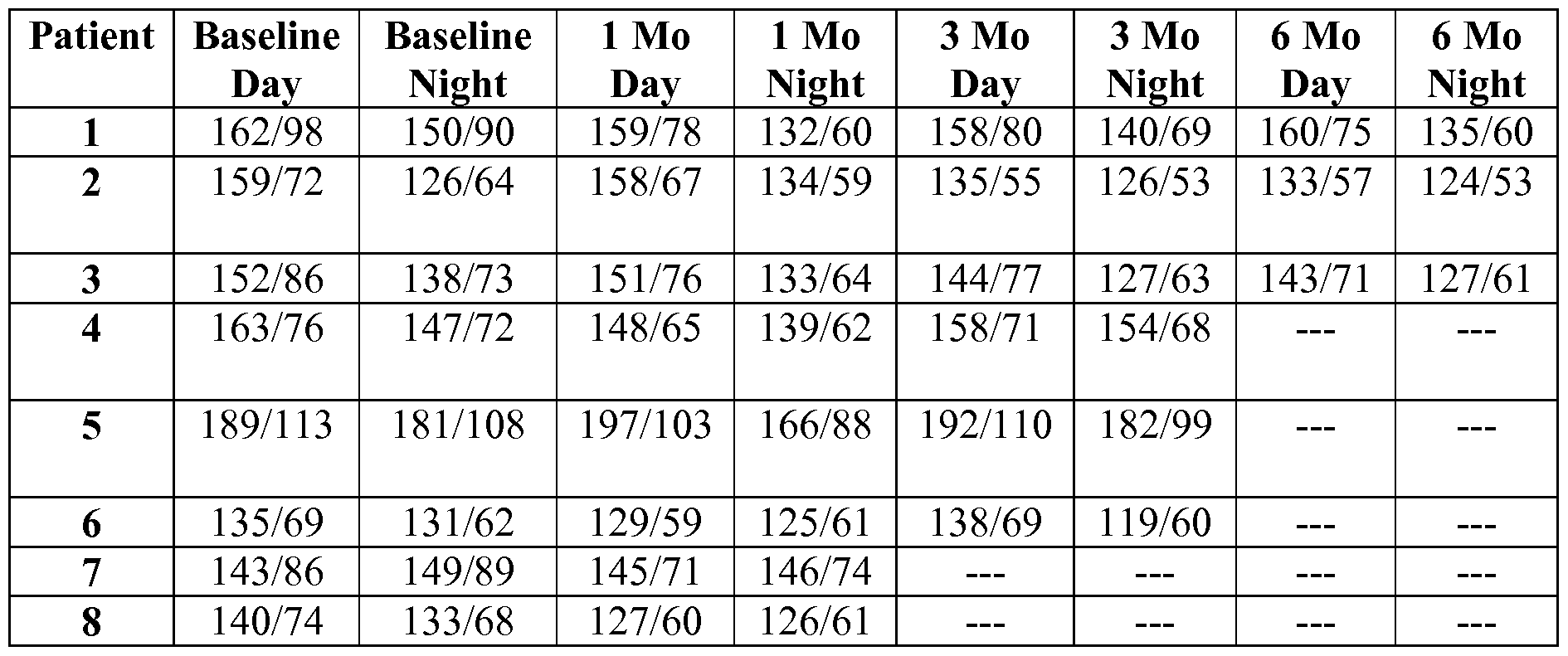
[0124] Table 4 herebelow represents average serum creatinine data for three patients who received the fistula creation procedure of the present inventive concepts. The data includes serum creatinine levels for three patients having Stage II Hypertension and elevated serum creatinine levels for four patients at baseline at baseline and three months, six months, nine months, and twelve months after the fistula creation procedure. The data indicates a sustained decrease in serum creatinine levels representative of increased kidney perfusion, thus improved renal function. The analysis showed no correlation between change in serum creatinine and weight over the course of the twelve months follow up.
Average serum creatinine levels for 3 Patients representative of increased kidney perfusion and improved renal function

[0125] Table 5 herebelow represents the results from an evaluation of cardiac function for patients who received the fistula creation procedure of the present inventive concepts. Echocardiogram results demonstrated no change, and in some cases, an improvement to cardiac function for those patients receiving the fistula creation procedure. Control data indicated a decline in cardiac function for some patients.
TABLE 5: Change in Cardiac Function: Data represented by # of patients/total # of patients

[0126] Referring now to Fig. 2, a system for creating a fistula between a first vascular location in a patient's arterial system of a patient (e.g. an artery), and a second vascular location in the patient's venous system (e.g. a vein), is illustrated. System 100 can be constructed and arranged to create a fistula to treat a cardiac arrhythmia of a patient and/or to improve a function of a cardiac structure. Alternatively or additionally, system 100 can be constructed and arranged to treat a patient disease or disorder selected from the group consisting of: chronic obstructive pulmonary disease; congestive heart failure; lung fibrosis; adult respiratory distress syndrome; lymphangioleiomytosis; pulmonary hypertension; sleep apnea such as sleep apnea due to hypoxemia or hypertension; and combinations of these. System 100 comprises a vascular introducer, first introducer 110, configured to be placed into the patient to provide access to a starting vessel. System 100 comprises another vascular introducer, second introducer 130, configured to provide access to a target vessel. In some embodiments, the starting vessel is a vein, and the target vessel is an artery. In other embodiments, the starting vessel is an artery and the target vessel is a vein. System 100 can include target wire 120 which comprises helical section 121 and is configured to be placed through the second introducer 130 and into the target vessel. Target wire 120 can be placed through an elongate tube, catheter 122. System 100 can comprise needle deployment device 140 which is configured to deploy crossing needle 145 (shown in an advanced position in Fig. 2), from the starting vessel and into the target vessel. System 100 can include a vessel- to-vessel guidewire 170, which can be placed from the starting vessel to the target vessel via needle deployment device 140. System 100 can also include clip deployment catheter 150, which is configured to deploy anastomotic clip 160. System 100 can include a fistula modifying device, such as dilation device 180 including balloon catheter 185 and standard angioplasty balloon indeflator 181. System 100 can further comprise imaging apparatus 190, typically a fluoroscope and/or ultrasound imaging device used to image one or more device or components of system 100, as well as the patient's anatomy, during the creation of an arteriovenous fistula.
[0127] First introducer 110 is configured to be placed into the patient to provide access to a starting vessel (e.g. a vein of a patient). In some embodiments, introducer 110 comprises an
I I French vascular introducer. First introducer 1 10 can comprise beveled tip 111 with an angle ranging from 20° to 50°, such as at an angle of approximately 30°. Additionally, system 100 can include a kit comprising an additional introducer having a second angle providing the clinician or other user (hereinafter "clinician) with more options as may be appropriate for a particular patient's anatomical geometry. In some embodiments, beveled tip
I I I comprises a marker, for example, a radiopaque or other visualizable marker, such that the luminal wall of the starting vessel can be imaged (e.g. when tip 111 is pressed against the vessel wall). The proximal portion of introducer 1 10 can comprise a contour or marker, such as to be correlated with or otherwise indicate the alignment of the bevel of tip 111.
[0128] Introducer 110 comprises shaft 117 which includes at least one thru lumen.
Introducer 110 also comprises port 116, typically a hemostasis valve, which is fluidly connected to the lumen of shaft 117. A second port 118, typically a luer connector, is connected to tubing 115 which in turn is connected to port 116. Introducer 110 can further comprise a dilator, not shown but typically an 11 to 13 Fr dilator used to introduce and/or pre-dilate tissue receiving introducer 110. Introducer 110 can further comprise a radially expandable element, such as expandable element 119, such as a balloon or expandable cage located on its distal portion. In some embodiments, expandable element 119 can be configured to prevent advancement of introducer 110 into the target vessel. In yet another embodiment, expandable element 119 can be configured to stabilize the starting vessel during insertion of introducer 110 or another device or component of system 100.
[0129] System 100 can comprise second introducer 130 which is configured to provide access to a target vessel, such as an artery of the patient when the starting vessel is a vein. In some embodiments, second introducer 130 comprises a 4 French vascular introducer. System 100 comprises target wire 120 configured to be placed through second introducer 130 and into the target vessel. Target wire 120 can comprise helical section 121 configured to be deployed at the site where the fistula is to be created. Helical section 121 can be configured to provide structure and support to the site during a procedure. Additionally, target wire 120 can serve as a visual reference during insertion of vessel-to-vessel guidewire 170, as described herebelow.
[0130] System 100 can comprise needle deployment device 140. Needle deployment device 140 comprises shaft 141 which slidingly receives advanceable crossing needle 145, shown in an advanced state. Shaft 141 comprises shaft hub 142 mounted to its proximal end.
Shaft 141 can comprise a curved distal portion as shown. Crossing needle 145 comprises needle hub 146 mounted to its distal end. Movement of needle hub 146 relative to shaft hub 142 causes crossing needle 145 to advance and retract within shaft 141. Needle hub 146 is fully advanced toward shaft hub 142 in the configuration of Fig. 2, such that the tip and distal portion of crossing needle 145 is fully advanced out of the distal end of shaft 141.
[0131] Crossing needle 145 can comprise a 20 to 24 gauge needle, such as a 22 gauge needle. In some embodiments, the crossing needle 145 comprises a curved distal portion (as shown). The curved distal portions of shaft 141 and/or needle 145 can be aimed at the center of the target vessel prior to insertion into the target vessel. The radius of curvature can be reduced if the clinician has difficulty in aiming the needle tip at the center of the target vessel prior to insertion. Conversely, the radius of curvature can be increased to sufficiently aim the needle tip at the center of the target vessel. Additionally, the crossing needle 145 can comprise a marker, not shown but indicating the direction of curvature. Examples of markers include, but are not limited to: a flat surface, a textured surface; a visualizable marker such as a radiopaque marker, a magnetic marker, an ultrasonic marker or a visible marker; and combinations of these. In some embodiments, crossing needle 145 can comprise a shaped memory alloy, for example, nickel titanium alloy. In some embodiments, shaft hub 142 and/or needle hub 146 comprise a marker or other visible demarcation (e.g. a flat portion) which correlates to the direction of curvature of shaft 141 and/or crossing needle 145, respectively.
[0132] System 100 can comprise a guidewire to be placed from the starting vessel to the target vessel, vessel-to-vessel guidewire 170. Guidewire 170 is configured to be placed via needle deployment device 140. In some embodiments, vessel-to-vessel guidewire 170 comprises a wire with an outer diameter of approximately 0.018". Vessel-to-vessel guidewire 170 can comprise a marker, not shown but configured to indicate the fistula location. In some embodiments, vessel-to-vessel guidewire 170 comprises a distal portion and a mid portion. Guidewire 170 mid portion can comprise a different construction than the distal portion. For example, the mid portion of guidewire 170 can be stiffer than the distal portion.
[0133] System 100 can comprise clip deployment catheter 150 configured to house and deploy anastomotic clip 160. Clip 160 comprises a plurality of distal arms 161 and a plurality of proximal arms 162, which can be deployed simultaneously or independently. Clip 160 comprises at least two distal arms 161 and at least two proximal arms 162 configured to deploy and engage the starting vessel and the target vessel. In some
embodiments, clip 160 comprises four deployable distal arms 161 and four deployable proximal arms 162. Clip 160 can comprise a shaped memory alloy, such as nickel titanium alloy. In some embodiments, clip 160 is constructed and arranged as described in applicant's U.S. Patent Number 7,828,814, entitled "Device and Method for Establishing an Artificial Arterio-Venous Fistula", filed April 4, 2007, the contents of which are incorporated herein by reference in its entirety.
[0134] In some embodiments, clip 160 is biodegradable or includes one or more
biodegradable portions (e.g. one or more portions of clip are absorbed or otherwise degrade over time). In some embodiments, clip 160 comprises a biodegradable anastomotic device such as is described in applicant's co-pending U.S. Non-Provisional Application Serial Number 12/752,397, entitled "Device and Method for Establishing an Artificial
Arteriovenous Fistula", filed April 1, 2010, the contents of which are incorporated herein by reference in its entirety.
[0135] Clip deployment catheter 150 comprises shaft 151. Mounted to the proximal end of shaft 151 is handle 153. On the proximal end of handle 153 is port 155, which is operably attached to shaft 151 such that a guidewire can travel from the distal end of shaft 151 to port 155, such as guidewire 170 after it has been previously placed between a starting vessel and a target vessel as has been described hereabove. Shaft 151 comprises one or more tubular portions, such as an inner tubular segment that houses clip 160, and an outer tubular segment that covers clip 160 but can be retracted to deploy clip 160, such as is described in applicant's co-pending U.S. Non-Provisional Application Serial Number 11/152,621, entitled "Devices for Arterio-Venous Fistula Creation", filed June 13, 2005, the contents of which is incorporated herein by reference in its entirety.
[0136] Handle 153 further includes control 152 (e.g. a button, slide or lever), where control 152 is operably configured to allow an operator to deploy distal arms 161 and/or proximal arms 162 of clip 160, such as via retraction of an outer tube or sheath portion of shaft 151 that is covering one or more portions of clip 160. In some embodiments, a click or other tactile feedback is provided during retraction of a sheath portion of shaft 151. Control 152 can be moved via a stepped or otherwise segmented slot 156. Distal arms 161 can be deployed via moving control 152 from a "first ready to deploy" position to a "first deployed" position which can be achieved by moving control 152 relatively parallel to the longitudinal axis of handle 153. The at least two proximal arms 162 can be queued to be deployed via moving control 152 from the first deployed position to a "second ready to deploy" position. The second ready to deploy position can be achieved by moving control 152 in a direction
perpendicular to the longitudinal axis of the handle. Subsequently, proximal arms 162 can deployed via moving control 152 from the second ready to be deployed position to a "second deployed" position via a motion parallel to the longitudinal axis of the handle. In this embodiment, control 152 can include a safety position comprising a ready to deploy position which can be transitioned by moving control 152 in a direction that is perpendicular to the axis of handle 153. This control advancement arrangement can prevent inadvertent deployment of distal arms 161 and/or proximal arms 162.
[0137] In some embodiments, prior to deployment of one or more arms of clip 160, introducer 110 can be advanced such that end 111 applies a force to the wall of the starting vessel. Sufficient force can be applied by introducer 110 to enable an operator to "seat" the starting vessel against the target vessel to assist in properly deployment of clip 160.
[0138] In some embodiments, catheter 150 can be configured to recapture distal arms 161 and/or proximal arms 162. For example, clip deployment catheter 150 can deploy at least one distal arm 161 and subsequently recapture the at least one distal arm 161.
[0139] Clip deployment catheter 150 and/or clip 160 can further comprise at least one marker, not shown but typically a radiopaque and/or ultrasonic marker configured to assist in the rotational positioning of clip 160 at the fistula location. For example, the marker can be oriented toward the target vessel prior to deployment of clip 160. In some embodiments, a marker is included on the distal portion of clip deployment catheter 150. In some
embodiments, handle 153 comprises one or more markers that are circumferentially aligned with clip 160 prior to its deployment. In some embodiments, clip deployment catheter 150 and/or clip 160 comprise at least one marker configured to longitudinally position clip 160 at the fistula location. In these embodiments, the marker can indicate the distal and/or proximal end of clip 160.
[0140] Clip deployment catheter 150 can further comprise a projection and/or recess, neither shown but configured to mechanically engage clip 160. The project and/or pin can be used to stabilize clip 160 with shaft 151, such as when an outer tubular portion of shaft 151 is advanced or retracted.
[0141] System 100 can comprise dilation device 180 configured to dilate clip 160 and/or the fistula. Dilation device 180 can include balloon catheter 185, such as a standard angioplasty balloon catheter comprising balloon 186. Attached to the proximal end of catheter 185 is indeflator 181, typically a standard balloon indeflator device. Alternatively, balloon 186 can comprise a non-balloon expandable such as an expandable cage or radially deployable arms configured to dilate the fistula. Catheter 185 is configured to track over a
vessel-to-vessel guidewire, such as guidewire 170 placed between a vein and an artery, such that balloon 186 is positioned within the fistula (e.g. within clip 160). Typically, dilation device 180 can expand to a diameter of less than five millimeters, and more typically to a diameter of approximately four millimeters. In some embodiments, a second dilation device 180 is included, such as a device configured to expand to a different diameter than the first dilation device.
[0142] System 100 can include patient imaging apparatus 190. Non-limiting examples of an imaging apparatus include: x-ray; fluoroscope; ultrasound imager; MRI; and combinations of these. The imaging apparatus can allow the clinician to track the movement of all components comprising system 100 as well as view the position of the starting and target vessel relative to each other, as described in detail herein.
[0143] System 100 can include an algorithm (e.g. a software based algorithm) used to create the fistula such as an algorithm using a patient parameter (e.g. blood pressure) to determine a fistula parameter such as fistula cross sectional area.
[0144] Referring now to Fig. 5, a flow chart of a method of creating a fistula between a starting vessel and a target vessel at a fistula location, consistent with the present inventive concepts is illustrated. In STEP 510, a procedural planning assessment of a patient is performed. STEP 520 comprises placing a first introducer into a starting vessel, e.g. a vein, and placing a second introducer into a target vessel, e.g. an artery. In STEP 530, an angiographic orientation is performed and a fistula location is selected. STEP 540 comprises placing a vessel-to-vessel guidewire between the vein and the artery. STEP 550 comprises placing an anastomotic clip at the fistula location. In some embodiments, system 100 and/or one or more components of system 100 of Fig. 2 are used to perform the method of Fig. 5.
[0145] The starting vessel can comprise a vein, and can be selected from the group consisting of: inferior vena cava (IVC); saphenous; femoral; iliac; popliteal; brachial; basilic; cephalic; medial forearm; medial cubital; axillary; and jugular. The target vessel can comprise an artery, and can be selected from the group consisting of: aorta; axillary;
brachial; ulnar; radial; profundal; femoral; iliac; popliteal and carotid. In a preferred embodiment, the starting vessel and target vessel comprise an external iliac. In an alternate embodiment, the starting vessel can comprise an artery and the target vessel can comprise a vein.
[0146] STEP 510, the first step in the illustrated method of the present inventive concepts comprises procedural planning. This step comprises properly orienting the vein and the artery, meaning a clinician becomes familiar with the anatomical orientation of the vein and
artery relative to each other. Understanding the orientation of the vessels with respect to one another can be achieved through analysis of one or more images provided by an imaging apparatus (e.g. a fluoroscope) such as imaging apparatus 190 of Fig. 2. In some
embodiments, at least one of the vein or artery has a diameter of at least five millimeters proximate the fistula location. In another embodiment, both the vein and artery have a diameter of at least five millimeters proximate the fistula location.
[0147] In STEP 520, the method comprises placing a first introducer into the vein.
Preferably, the first introducer comprises an 11 French introducer having a beveled tip, such as introducer 110 of Fig. 2 described hereabove. In some instances, the beveled tip of the first introducer can be rotated during insertion into the vein. Rotation of the introducer can be helpful during insertion into the starting vessel due to the tendency of the beveled tip to lift and pull back. Additionally or alternatively, the introducer can be vibrated while it is advanced into the vein. STEP 520 can further comprise pre-dilating the vein with a dilator, preferably a 13 French dilator, prior to placing the introducer into the vein. Additionally, a second introducer can be placed into the artery. Preferably, the second introducer comprises a 4 French introducer, such as introducer 130 described in Fig. 2 hereabove. The method further comprises placing a target wire into the second introducer and then into the artery such that the distal end of the target wire is positioned five to ten centimeters past the fistula location, and configured to serve as a visual reference to a clinician. The target wire, typically including a helical section, is advanced. The advancement can be combined with retracting the introducer such that the helical section of the wire is deployed at the targeted anastomotic site.
[0148] In STEP 530, the method comprises performing angiographic orientation and selecting a fistula location. Choosing the fistula location can be based upon a lack of thrombus or other soft tissue occlusive matter at the vascular location, as well as lack of plaque or calcified matter. Preferably, the fistula location is chosen at a location where the vein is less than or equal to three millimeters apart from the artery. Techniques can be used to image the vein and artery in side-by-side configurations as well as overlapping (i.e. on top of each other in the image) orientations. Rotation of the imaging device 90° can modify the provided image from a side-by-side image to an overlapping image, and back again. In some embodiments, after a fistula location has been selected, a clinician can orient the fluoroscope such that the vein and artery are shown overlapping, such as with the vein on top of the artery. In some embodiments, the clinician can position a fluoroscope or other imaging device at an angle to the patient approximating 35° RAO.
[0149] In STEP 540, the method comprises placing a vessel-to-vessel guidewire into the vein, such as while the vein and artery are imaged in an overlapping orientation, as described in STEP 530 hereabove. A next step comprises placing a needle delivery device over the vessel-to-vessel guidewire and into the vein. The needle delivery device can comprise a marker, as described in Fig. 2 hereabove, such that a clinician can orient the marker toward the artery. The guidewire can be retracted and subsequently, the needle of the needle delivery device can be advanced toward the target wire and toward the artery. In some embodiments, the vessel-to-vessel guidewire can be placed through a dilator.
[0150] Prior to inserting the crossing needle into the artery, a clinician can aim the needle tip at the center of the artery to ensure desired engagement of the artery with the needle, such as by rotating the proximal end of the needle or a device containing the needle. In some embodiments, the needle or needle delivery device includes a proximal hub with a
demarcation (e.g. a flat portion or a marker) positioned to indicate the orientation of a curved distal portion of the needle, such as is described in reference to deployment device 140 of Fig. 2 hereabove. In this operation, a clinician can torque or otherwise rotate the needle such that the direction of the needle curvature comes into view on the imaging apparatus (e.g. fluoroscope). Confirming the direction of needle curvature ensures that the needle is to be advanced in the desired direction, such as into the center of the artery. In some embodiments, a target wire is placed in the target vessel, such as vessel-to-vessel guidewire 170 of Fig. 2 described hereabove. Preferably, the needle comprises a curved tip, and the radius of curvature can be reduced if a clinician has difficulty in aiming the needle at the center of the target vessel prior to insertion. Conversely, the radius of curvature can be increased to sufficiently aim the needle tip at the center of the target vessel. In some embodiments, the needle delivery catheter is oriented as described in reference to Fig. 6 herebelow.
[0151] Additionally, a clinician can confirm that the distal portion of the vessel-to-vessel guidewire is located within the lumen of the artery. Also, the clinician can confirm the vessel-to-vessel guidewire is parallel with the target wire previously placed in the artery. A clinician can confirm that the needle is positioned within the target vessel by using a dye injection through the needle. Alternatively or additionally, a clinician can confirm that the needle is properly positioned in a target vessel by measuring the pressure in a distal portion of the needle, such as to confirm presence in an artery by confirming arterial pressure is recorded.
[0152] In some embodiments, the needle delivery device is placed into the artery and the guidewire is advanced from the artery into the vein via the crossing needle. In these
embodiments, the anastomotic clip delivery catheter can also be advanced from artery to vein.
[0153] In STEP 550, the method comprises placing an anastomotic clip at a fistula location. Prior to performing STEP 550, placing an anastomotic clip at a fistula location, a user can retract the crossing needle while maintaining the position of the target wire. Next, the target wire can be removed from the second introducer. The target wire can also be removed after STEP 550.
[0154] In STEP 550, a user can position the vein and artery such that the vein and artery are slightly apart from each other on the image (e.g. not overlapping). In one embodiment, this can be achieved by rotating a fluoroscopy unit 45° to 90° after an overlapping image is obtained (e.g. an image obtained during a dual contrast injection of both the artery and vein).
[0155] Next, the tip of the clip deployment catheter (with a pre-loaded anastomotic clip) can be placed at the fistula site. In this step, a clinician can apply forward pressure and rotate the clip deployment catheter. The clip can comprise at least two distal arms and at least two proximal arms that can be deployed simultaneously or independently via a control located on the handle of the catheter.
[0156] STEP 550 further comprises deploying the anastomotic clip in the fistula, such as is described in detail in reference to clip deployment catheter 150 of Fig. 2 hereabove. The clip distal arms are deployed by moving a control on the clip deployment catheter from a ready to deploy position to a first deployed position, which can be achieved by moving the control relatively parallel to the longitudinal axis of the handle. Prior to deploying the proximal arms of the clip, a clinician can retract the first introducer to the fistula location and seat the vein against the artery. The clip deployment catheter can comprise a marker located on its distal end. Using this marker, a clinician can pull the clip deployment catheter back such that the marker is aligned with the distal end of the first introducer.
[0157] In a next operation of STEP 550, the proximal arms can be queued to be deployed via moving the control from a first deployed position to a second ready to deploy position. The ready to deploy position can be achieved by moving the control in a direction
perpendicular to the longitudinal axis of the handle. Subsequently, the proximal arms can be deployed via moving the control from the second ready to be deployed position to the second deployed position via a motion parallel to the longitudinal axis of the handle. In this embodiment, the control includes a safety position comprising a ready to deploy position which can be transitioned by moving the control in a direction that is perpendicular to the axis of the handle. This control arrangement can prevent inadvertent deployment of the distal
and/or proximal arms. After deployment of the proximal arms, a clinician can retract the first introducer from the anastomosis site, such as a retraction of approximately two to three centimeters, followed by retracting the clip deployment catheter.
[0158] The method can further comprise dilating the fistula via a balloon or other expandable member. For example, a clinician can track a balloon catheter over the target wire and inflate the balloon. In a typical embodiment, the balloon catheter comprises a diameter of four to five millimeters and can be inflated via a four millimeter by one and one half centimeter non-conforming balloon and indeflator device. The balloon then can be deflated and retracted out of the implant.
[0159] The method can further comprise verifying clip patency. This can be achieved via a contrast/saline solution injected into the second introducer. A clinician can then remove all devices once it is confirmed that the clip is positioned as desired.
[0160] The method can further comprise placing a second anastomotic clip, such as a second anastomotic clip 160 of Fig. 2 described hereabove. Alternatively or additionally, the method can further comprise creating a second fistula between, such as a second fistula created during the same clinical procedure or a subsequent clinical procedure. The second fistula can be between the same two vascular locations as the first fistula, or one or both of the second fistula vascular locations can be different (e.g. a different vein and/or artery).
[0161] Referring now to Fig. 6, an angiographic view of a patient's vein and artery prior to advancement of a needle into the artery is illustrated, such as may be performed in STEP 540 of the method of Fig. 5 described hereabove, consistent with the present inventive concepts. In the illustrated embodiment, a clinician has oriented an imaging device (e.g. a fluoroscope or other imaging device of Fig. 1), such that the segments of vein and artery at a proposed fistula location are overlapping (i.e. on top of each other in the image). The clinician has placed a target wire, such as target wire 120 of Fig. 1, into a patient's artery such that the helical portion 121 of wire is positioned at the proposed fistula location.
Additionally, needle deployment device 140 has been advanced intraluminally through the vein as shown such that its distal end is proximal to the proposed fistula location. A next step comprises advancing needle 145 toward the helical portion 121 of wire 120 at the proposed fistula location.
[0162] Prior to insertion of needle 145 into the artery, a clinician can rotate needle deployment device 140 such that the direction of the needle deployment device 140 curvature is viewed (i.e. a non-linear, curved segment is visualized) on the imaging apparatus.
Confirming the direction of curvature ensures that needle 145 is to be advanced in the desired
direction, such as into the center of the artery. For example, if a clinician rotates needle deployment device 140 such that its tip is positioned as shown in Figs. 6A or 6C, a clinician will be aiming to an off-center location of the patient's artery. If a clinician rotates needle deployment device 140 such that its tip is positioned as shown if Fig. 6B, needle 145 will subsequently be advanced into the relative center of the patient's artery. The radius of curvature of a needle deployment device 140 can be reduced (e.g. by manual reshaping or by selected a different needle deployment device 140) if a clinician has difficulty in aiming needle 145 at the center of the artery prior to insertion. Conversely, the radius of curvature of needle deployment device 140 can be increased to create a more desirable needle 145 advancement trajectory.
[0163] Referring now to Fig. 7, a perspective view of an anastomotic clip is illustrated, consistent with the present inventive concepts. Clip 160 can comprise at least two distal arms 161 and at least two proximal arms 162. In the illustrated embodiment, clip 160 comprises four distal arms 161 and four proximal arms 162.
[0164] Clip 160 can be formed from a single tube of resilient material, such as nickel titanium alloy, spring steel, glass or carbon composites or polymers, or pseudoelastic (at body temperature) material such as nickel titanium alloy or comparable alloys and polymers, by laser cutting several closed-ended slots along the length of the tube (leaving the extreme distal and proximal edges of the tube intact) and cutting open-ended slots from the longitudinal center of the tube through the distal and proximal edges of the tube. The open- ended slots are cut between each pair of closed-end slots to form a number of loops joined at the center section by waist segments. Many other fabrication techniques can be utilized, for example, clip 160 can be made of several loops of wire welded together at the waist section.
[0165] After the tube is cut as described above, it is formed into its eventual resiliently expanded configuration. In this configuration, the loops turn radially outwardly from the center section, and evert toward the center plane of the center section, thus forming clinch members, i.e. distal arms 161 and proximal arms 162, in the form of arcuate, everted, petaloid frames at either end of the loop, extending from the generally tubular center section formed by waist segments. For clarity, the term everted is used here to mean that the arc over which the petaloid frame runs is such that the inside surface of clip 160 faces radially outwardly from the cylinder established by the tube.
[0166] Once clip 160 has resiliently expanded to the extent possible given its impingement upon the walls of the starting vessel and the target vessel, the center section can be further expanded by plastic deformation. This can be accomplished by inflating a balloon, not
shown, within the center section and expanding the center section beyond its elastic or superelastic deformation range. By plastically deforming the center section of clip 160, the center section becomes more rigid and able to withstand the compressive force of the walls of the starting and target vessels.
[0167] As illustrated, the construction provides several pairs of longitudinally opposed (that is, they bend to come into close proximity to each other, and perhaps but not necessarily, touch) and aligned (they are disposed along the same longitudinal line) distal arms 161 and proximal arms 162. Overall, the petaloid frames of distal arms 161 form a "corolla," analogous to the corolla of a flower, flange or rivet clinch, which impinges on the starting vessel wall and prevents expulsion into the target vessel, and the petaloid frames of proximal arms 162 form a corolla, flange or rivet clinch (this clinch would be analogous to a rivet head, but it is formed like the clinch after insertion of the rivet), which impinges on the target vessel wall and prevents the expulsion of clip 160 into the target vessel. Also, the central section forms a short length of rigid tubing to keep the fistula open. The resilient apposition of the at least two distal arms 161 and at least two proximal arms 162 will securely hold clip 160 in place by resiliently clamping the walls of the starting vessel and the target vessel, even over a considerable range of wall thickness or "grip range."
[0168] The respective lengths of arms 161 and 162 can be variably sized to maximize or optimize the stability of clip 160 with respect to the vessels when deployed between adjacent vessels. Moreover, varying the lengths of the respective arms can further provide additional advantages. For instance, the arms which are shortened in length can facilitate the positioning and securement of clip 160 between the vessels by allowing for the relatively shorter member to swing into position within the vessel lumen during deployment, as described in further detail below. Additionally, a shorter member can provide for a minimized implant size when placed against the vessel interior wall for securement as well as a mitigating any physiologic reaction to the implant, e.g., a reduction in thrombosis, etc. Additionally, arms 161 and/or 162 which are lengthened relative to other arms can provide for increased clip stability by increasing the amount of force applied against the tissue walls.
[0169] Moreover, arms having different lengths can additionally place the adjacent vessels in tension such that the vessel walls are drawn towards one another and arms 161 and/or 162 contact the vessel luminal walls to stabilize not only clip 160 within the vessels but also the vessels with respect to one another. Additionally, having one or more arms, such as distal arms 161, sized to have a length shorter than its respective apposed clinch member can also facilitate the deployment and/or positioning of distal arms 161 within the vessel since the
shorter length clinch members can more easily "swing" through an arc within the vessel lumen without contacting the interior walls. Arms with differing lengths can further be configured to align along different planes when deployed to facilitate vessel separation, if so desired.
[0170] Clip 160 can further comprise at least one marker, not shown, configured to rotationally position the clip at the fistula location. For example, a marker can be oriented toward the target vessel prior to deployment of clip 160. Alternatively or additionally, a marker can be oriented based upon a patient image, e.g. a real-time fluoroscopy image. In yet another embodiment, clip 160 can comprise at least one marker configured to longitudinally position the clip at the fistula location. A marker can indicate the distal and/or proximal end of clip 160.
[0171] Clip 160 can further comprise holes 164 configured to engage a clip delivery catheter projection such as to allow the shaft of the clip deployment catheter, not shown, to be retracted while clip 160 remains positioned in the distal portion of the shaft. In one embodiment, holes 164 are constructed and arranged about the clip asymmetrically such that clip 160 can be attached in the proper orientation.
[0172] While the preferred embodiments of the devices and methods have been described in reference to the environment in which they were developed, they are merely illustrative of the principles of the inventions. Modification or combinations of the above-described assemblies, other embodiments, configurations, and methods for carrying out the invention, and variations of aspects of the invention that are obvious to those of skill in the art are intended to be within the scope of the claims. In addition, where this application has listed the steps of a method or procedure in a specific order, it may be possible, or even expedient in certain circumstances, to change the order in which some steps are performed, and it is intended that the particular steps of the method or procedure claim set forth herebelow not be construed as being order-specific unless such order specificity is expressly stated in the claim.
Claims
A method of treating a patient comprising:
selecting a patient for treatment; and
creating a flow pathway between a first vascular location and a second vascular location;
wherein the method is constructed and arranged to provide at least one of:
a therapeutic treatment of a cardiac arrhythmia or an improvement of a function of a cardiac structure.
The method of claim 1 wherein the patient exhibits an arterial blood pressure greater than 180mmHg prior to creation of the flow pathway.
The method of claim 1 wherein the patient exhibits an arterial blood pressure between 160mmHg and 180mmHg prior to creation of the flow pathway.
The method of claim 1 wherein the patient exhibits an arterial blood pressure between 130mmHg and 160mmHg prior to creation of the flow pathway.
The method of claim 1 wherein the patient has been diagnosed with renal artery calcification.
The method of claim 1 wherein the patient has been diagnosed with compromised kidney function.
The method of claim 6 wherein the patient has been diagnosed with kidney failure. The method of claim 1 wherein the first vascular location comprises a source of arterial blood.
The method of claim 8 wherein the first vascular location comprises an artery selected from the group consisting of: aorta; axillary; brachial; ulnar; radial;
profundal; femoral; iliac; popliteal; and carotid.
The method of claim 8 wherein the second vascular location comprises a source of venous blood.
The method of claim 10 wherein the second vascular location comprises a vein selected from the group consisting of: inferior vena cava; saphenous; femoral; iliac; popliteal; brachial; basilic; cephalic; medial forearm; medial cubital; axillary; and jugular.
The method of claim 1 wherein the flow pathway comprises a fistula.
The method of claim 1 wherein the flow pathway comprises an anastomosis.
14. The method of claim 1 wherein the flow pathway comprises an anatomical location relatively proximate to a kidney of the patient.
15. The method of claim 1 wherein the flow pathway comprises an anatomical location positioned at a location that comprises an infrarenal anatomical location.
16. The method of claim 15 wherein the first vascular location comprises an artery.
17. The method of claim 1 wherein the flow pathway comprises an anatomical location positioned at a location that comprises a supra-renal anatomical location.
18. The method of claim 17 wherein the first vascular location comprises an artery.
19. The method of claim 1 wherein the first vascular location comprises a chamber of the heart.
20. The method of claim 19 wherein the first vascular location comprises the left atrium and the second vascular location comprises the right atrium.
21. The method of claim 19 wherein the first vascular location comprises the left
ventricle and the second vascular location comprises the coronary sinus.
22. The method of claim 1 wherein the first vascular location comprises the aorta and the second vascular location comprises a vein, and wherein the flow pathway comprises a graft positioned between the aorta and the vein.
23. The method of claim 1 wherein the flow pathway comprises an average cross
sectional area of less than 20mm .
24. The method of claim 23 wherein the flow pathway comprises an average cross sectional area of less than 12.6mm .
25. The method of claim 23 wherein the flow pathway comprises an average cross sectional area of less than 9.7mm .
26. The method of claim 23 wherein the flow pathway comprises an average cross sectional area of less than 7.1mm .
27. The method of claim 1 wherein the average cross sectional area of the flow pathway is selected based on a patient parameter.
28. The method of claim 27 wherein the patient parameter is a patient blood pressure parameter.
29. The method of claim 28 wherein the flow pathway average cross sectional area is proportionally related to the patient blood pressure parameter.
30. The method of claim 1 wherein the cardiac arrhythmia treated comprises atrial fibrillation.
31. The method of claim 30 wherein the method reduces atrial fibrillation occurrence.
32. The method of claim 30 wherein the method provides a therapeutic treatment for a patient disease selected from the group consisting of: chronic atrial fibrillation; persistent atrial fibrillation; paroxysmal atrial fibrillation; and combinations thereof.
33. The method of claim 30 wherein treating the cardiac arrhythmia comprises reducing systemic arterial pressure.
34. The method of claim 1 wherein the cardiac arrhythmia treated comprises an
arrhythmia selected from the group consisting of: ventricular tachycardia; right atrial flutter; atrial fibrillation; and combinations thereof.
35. The method of claim 1 wherein the method improves a function of a cardiac
structure to treat valve regurgitation.
36. The method of claim 35 wherein the method treats regurgitation of a valve selected from the group consisting of: mitral valve; aortic valve; and combinations thereof.
37. The method of claim 1 wherein the method treats a patient condition selected from the group consisting of: valve regurgitation; valve insufficiency; chronic high left heart pressures; and combinations thereof.
38. The method of claim 1 wherein the method is further constructed and arranged to reduce central sympathetic neural activity.
39. The method of claim 1 wherein the method is further constructed and arranged to reduce a patient parameter selected from the group consisting of: peripheral vascular resistance; left ventricular pre-load; left ventricular pressure; left atrial volume; left atrial volume; left atrial stretching; and combinations thereof.
40. The method of claim 1 wherein the method is further constructed and arranged to reduce the likelihood of blood clot formation.
41. The method of claim 1 wherein the method is further constructed and arranged to provide a treatment for systemic arterial hypertension.
42. The method of claim 41 wherein the method provides a treatment for drug-resistant hypertension.
43. The method of claim 1 wherein the method is further constructed and arranged to reduce diastolic blood pressure.
44. The method of claim 43 wherein the method is further constructed and arranged to reduce systolic blood pressure.
45. The method of claim 44 wherein the reduction in diastolic blood pressure and the reduction in systolic blood pressure are relatively equivalent in magnitude.
46. The method of claim 1 wherein the method is further constructed and arranged to provide a reduction in systolic blood pressure.
47. The method of claim 1 wherein the method is constructed and arranged to provide an increase to the compliance of the arterial vascular system.
48. The method of claim 47 wherein the method causes a release of at least one of
chemo-receptors or a vaso-dilating factor.
49. The method of claim 47 wherein the flow pathway is created based on a
measurement of at least one of vascular tone or vascular compliance.
50. The method of claim 1 wherein the method is constructed and arranged to lower blood pressure within a patient organ.
51. The method of claim 50 wherein the patient organ comprises an organ selected from the group consisting of: liver; kidney; heart; brain; and combinations thereof.
52. The method of claim 1 wherein the method is further constructed and arranged to treat a patient disease or disorder selected from the group consisting of: chronic obstructive pulmonary disease; congestive heart failure; lung fibrosis; adult respiratory distress syndrome; lymphangioleiomytosis; pulmonary hypertension; sleep apnea such as sleep apnea due to hypoxemia or hypertension; and
combinations thereof.
53. The method of claim 1 further comprising performing a second treatment on the patient.
54. The method of claim 53 wherein the second treatment comprises administering a pharmaceutical agent to the patient.
55. The method of claim 54 wherein the pharmaceutical agent comprises an agent
selected from the group consisting of: anti-arrhythmia drug; anti-thrombotic agent; and combinations thereof.
56. The method of claim 53 wherein the second treatment comprises performing the Cox-Maze procedure on the patient.
57. The method of claim 53 wherein the second treatment comprises performing a
cardiac ablation procedure on the patient.
58. The method of claim 57 wherein the cardiac ablation procedure comprises a surgical ablation procedure.
59. The method of claim 57 wherein the cardiac ablation procedure comprises an ablation procedure performed with interventional catheter devices.
60. The method of claim 57 wherein the cardiac ablation procedure comprises at least a pulmonary vein isolation ablation procedure.
61. The method of claim 57 wherein the cardiac ablation procedure comprises a cardiac ablation procedure selected from the group consisting of: ablation to isolate one or more pulmonary veins; ablation of the left atrial posterior wall; ablation of the left atrial septum; and combinations thereof.
62. The method of claim 57 wherein the cardiac ablation procedure comprises delivery of energy to cardiac tissue wherein the energy delivered is selected from the group consisting of: radio frequency energy; laser energy; ultrasound energy; chemical energy; and combinations thereof.
63. The method of claim 53 wherein the second treatment comprises treating a heart valve.
64. The method of claim 63 wherein the heart valve treatment comprises a
valvuloplasty procedure.
65. The method of claim 53 wherein the second treatment comprises a renal denervation procedure.
66. The method of claim 65 wherein the flow pathway is created in a clinical procedure and the renal denervation procedure is performed in the same clinical procedure in which the flow pathway is created.
67. The method of claim 65 wherein the flow pathway is performed in a clinical
procedure and the renal denervation procedure is performed in a previous clinical procedure than the clinical procedure in which the flow pathway is created.
68. The method of claim 65 wherein the flow pathway is performed in a clinical
procedure and the renal denervation procedure is performed in a subsequent clinical procedure than the clinical procedure in which the flow pathway is created.
69. The method of claim 65 wherein the flow pathway is created based on a blood
pressure reduction caused by the renal denervation procedure.
70. The method of claim 69 wherein the blood pressure reduction comprises a reduction in at least one of systolic blood pressure or diastolic blood pressure.
71. The method of claim 53 wherein the second treatment comprises placing a stent in a renal vessel.
72. The method of claim 53 wherein the second treatment comprises dilating a renal vessel.
73. The method of claim 53 wherein the flow pathway is created in a clinical procedure and the second treatment is performed in the same clinical procedure in which the flow pathway is created.
74. The method of claim 53 wherein the second treatment is performed within twenty four hours of creation of the flow pathway.
75. The method of claim 53 wherein the flow pathway is created in a clinical procedure and the second procedure is performed in a previous clinical procedure than the clinical procedure in which the flow pathway is created.
76. The method of claim 75 wherein the previous clinical procedure is performed at least one week prior to the clinical procedure in which the flow pathway is created.
77. The method of claim 75 wherein the previous clinical procedure is performed at least six months prior to the clinical procedure in which the flow pathway is created.
78. The method of claim 53 wherein the flow pathway is created in a clinical procedure the second procedure is performed in a subsequent clinical procedure than the clinical procedure in which the flow pathway is created.
79. The method of claim 78 wherein the subsequent clinical procedure is performed at least one week after the clinical procedure in which the flow pathway is created.
80. The method of claim 78 wherein the subsequent clinical procedure is performed at least six months after the clinical procedure in which the flow pathway is created.
81. The method of claim 1 further comprising performing a diagnostic procedure to produce diagnostic data.
82. The method of claim 81 wherein the diagnostic data comprises patient diagnostic data.
83. The method of claim 81 wherein the creation of the flow pathway is performed
based on the diagnostic data.
84. The method of claim 83 wherein the diagnostic data comprises blood pressure data.
85. The method of claim 84 wherein the blood pressure data is obtained over a period of at least sixty minutes.
86. The method of claim 81 wherein the flow pathway comprises an average cross
sectional area and wherein the average cross sectional area is based on the diagnostic data.
87. The method of claim 86 wherein the diagnostic data comprises blood pressure data.
88. The method of claim 87 wherein the blood pressure data is obtained over a period of at least sixty minutes.
89. The method of claim 81 wherein the diagnostic procedure produces patient
diagnostic data selected from the group consisting of: central blood pressure data; vascular tone data; central sympathetic tone data; cardiac output data; peripheral vascular resistance data; and combinations thereof.
90. The method of claim 1 wherein the method is constructed and arranged to cause a decrease in vascular resistance.
91. The method of claim 90 wherein the method is constructed and arranged to cause a decrease in peripheral vascular resistance.
92. The method of claim 91 wherein the method is constructed and arranged to cause a decrease in infrarenal vascular resistance.
93. The method of claim 1 wherein the method is further constructed and arranged to cause a physiologic change in the patient selected from the group consisting of: increased oxygen delivery by the arterial system; increased blood volume; increased proportion of blood flow to the descending aorta; increased blood flow to the kidneys; increased blood flow outside the kidneys; increased cardiac output; and combinations thereof.
94. The method of claim 1 wherein the method is further constructed and arranged to minimize chronic increase in heart rate.
95. The method of claim 1 wherein the method is further constructed and arranged to minimize a decrease in cardiac function.
96. The method of claim 1 wherein the method is further constructed and arranged to minimize adverse effects to a kidney of the patient.
97. The method of claim 1 wherein the method is further constructed and arranged to cause at least one of an increase in oxygenation or an increase in flow rates associated with the patient's chemo-receptors.
98. The method of claim 1 wherein the method is further constructed and arranged to modify the patient's central sympathetic tone.
99. The method of claim 98 wherein the modification to the patient's central
sympathetic tone causes a reduction in at least one of systolic or diastolic blood pressure.
100. The method of claim 98 wherein the modification to the patient's central sympathetic tone provides a therapeutic benefit to a patient disease or disorder selected from the group consisting of: diabetes; sleep apnea; heart failure; and combinations thereof.
101. The method of claim 1 further comprising dilating the flow pathway.
102. The method of claim 101 wherein the dilation is performed by inflating a balloon in the flow pathway.
103. The method of claim 101 wherein the dilation is performed at a diameter between 3mm and 5mm.
104. The method of claim 103 wherein the dilation is performed at a diameter of
approximately 4mm.
105. The method of claim 1 further comprising performing a flow pathway assessment procedure.
106. The method of claim 105 wherein the flow pathway assessment procedure
comprises performing an anatomical measurement.
107. The method of claim 106 wherein the anatomical measurement comprises a
measurement selected from the group consisting of: a flow pathway diameter measurement; a flow pathway length measurement; a measurement of the distance between an artery and vein comprising the flow pathway; a measurement of the distance between the flow pathway and a vessel sidebranch; and combinations thereof.
108. The method of claim 105 wherein the flow pathway assessment procedure
comprises performing an assessment of at least one of flow in the flow pathway or flow proximate the flow pathway.
109. The method of claim 108 wherein the assessment comprises a flow assessment selected from the group consisting of: flow through the flow pathway; flow in a vessel segment proximate the flow pathway; flow measured using Doppler Ultrasound; flow measured using angiographic techniques; and combinations thereof.
110. The method of claim 105 wherein the flow pathway assessment procedure
comprises an assessment of a patient physiologic condition.
111. The method of claim 110 wherein the patient physiologic condition comprises a condition selected from the group consisting of: cardiac output; blood pressure such as systolic and/or diastolic blood pressure; respiration; a blood gas parameter; blood flow; vascular resistance; pulmonary resistance; an average clotting time assessment; serum creatinine level assessment; and combinations thereof.
112. The method of claim 1 further comprising placing an implant in the flow pathway.
113. The method of claim 112 wherein the implant comprises an anastomotic clip.
114. The method of claim 112 wherein the implant comprises an implant selected from the group consisting of: suture; staple; adhesive; and combinations thereof.
115. The method of claim 112 wherein the implant comprises at least a portion that comprises biodegradable material.
116. The method of claim 1 further comprising modifying the flow pathway.
117. The method of claim 116 wherein the modifying the flow pathway comprises
dilating at least a portion of the flow pathway.
118. The method of claim 116 further comprising placing an anastomotic clip in the flow pathway and wherein the modifying the flow pathway is performed after the placement of the anastomotic clip.
119. The method of claim 116 wherein the modifying the flow pathway is performed at least one week after the creating of the flow pathway.
120. The method of claim 116 wherein the modifying the flow pathway comprises
modifying a flow parameter selected from the group consisting of: flow pathway cross sectional diameter; flow pathway average cross sectional diameter; flow pathway flow rate; flow pathway average flow rate; diastolic pressure after flow pathway creation; diastolic pressure change after flow pathway creation (e.g. as compared to diastolic pressure prior to flow pathway creation); systolic pressure after flow pathway creation; systolic pressure change after flow pathway creation (e.g. as compared to systolic pressure prior to flow pathway creation); ratio of diastolic to systolic pressure after flow pathway creation; difference between diastolic pressure and systolic pressure after flow pathway creation; and
combinations thereof.
121. The method of claim 116 wherein the modifying the flow pathway comprises a flow modification procedure selected from the group consisting of: increasing flow through the flow pathway; decreasing flow through the flow pathway; increasing the diameter of at least a segment of the flow pathway; decreasing the diameter of at least a segment of the flow pathway; removing tissue proximate the flow pathway; blocking a sidebranch proximate the flow pathway; and combinations thereof.
122. The method of claim 1 further comprising creating a second flow pathway between a third vascular location and a fourth vascular location.
123. The method of claim 122 wherein the first vascular location comprises an artery and the third vascular location comprises the same artery.
124. The method of claim 123 wherein the second vascular location comprises a vein and the fourth vascular location comprises the same vein.
125. The method of claim 122 wherein the second flow pathway comprises a fistula.
126. The method of claim 122 wherein the second flow pathway is created at least
twenty four hours after the creation of the first flow pathway.
127. The method of claim 122 further comprising occluding the first flow pathway.
128. A system constructed and arranged to create and maintain the flow pathway of the method of any of claims 1 thru 127.
129. The system of claim 128 further comprising an algorithm for determining average fistula cross sectional area.
130. The system of claim 129 wherein the algorithm is constructed and arranged to
determine average fistula cross sectional area based on a patient parameter.
131. The system of claim 130 wherein the patient parameter comprises a patient blood pressure parameter.
132. A system for treating a patient, comprising:
a needle delivery device constructed and arranged to place a vessel-to-vessel guidewire from a first vascular location to a second vascular location;
a flow creation device constructed and arranged to be advanced over the vessel-to- vessel guidewire and to create a flow pathway between the first vascular location and the second vascular location;
wherein the system is constructed and arranged to treat a cardiac arrhythmia.
133. The system of claim 132 wherein the cardiac arrhythmia comprises atrial
fibrillation.
134. The system of claim 132 further comprising an algorithm for determining average fistula cross sectional area.
135. The system of claim 134 wherein the algorithm is constructed and arranged to determine average fistula cross sectional area based on a patient parameter.
136. The system of claim 135 wherein the patient parameter comprises a patient blood pressure parameter.
137. The method of claim 132 wherein the system is further constructed and arranged to cause a reduction in systolic blood pressure.
138. The system of claim 132 wherein the system is further constructed and arranged to cause a reduction in diastolic pressure to an extent at least approximating a reduction in systolic pressure.
139. The system of claim 138 wherein the system is further constructed and arranged to cause a reduction in diastolic pressure to an extent greater than a reduction in systolic pressure.
140. The system of claim 132 wherein the needle delivery device comprises an
advanceable needle.
141. The system of claim 132 wherein the needle delivery device comprises a needle with a gauge between 20 and 24.
142. The system of claim 141 wherein the needle comprises an approximately 22 gauge needle.
143. The system of claim 132 wherein the needle delivery device comprises a curved needle.
144. The system of claim 143 wherein the needle delivery device further comprises a marker indicating the direction of curvature of the curved needle.
145. The system of claim 144 wherein the marker comprises a marker selected from the group consisting of: flat surface, visible marker, line, textured surface, and combinations thereof.
146. The system of claim 143 wherein the needle delivery device further comprises a sheath constructed and arranged to slidingly receive the curved needle.
147. The system of claim 146 wherein the needle comprises a proximal end and a hub positioned on said proximal end.
148. The system of claim 147 wherein the hub is constructed and arranged to be
advanced to advance the curved needle out of the sheath.
149. The system of claim 132 wherein the needle delivery device comprises a needle comprising a shaped memory alloy.
150. The system of claim 149 wherein the shaped memory alloy comprises nickel
titanium alloy.
151. The system of claim 132 further comprising a vessel-to-vessel guidewire
constructed and arranged to be placed from the first vascular location to the second vascular location by the needle delivery device.
152. The system of claim 151 wherein the vessel-to-vessel guidewire comprises a wire with an outer diameter approximating 0.018".
153. The system of claim 151 wherein the vessel-to-vessel guidewire comprises a
marker.
154. The system of claim 153 wherein the marker is positioned to indicate the fistula location.
155. The system of claim 151 wherein the vessel-to-vessel guidewire comprises a distal portion and a mid portion and wherein the mid portion comprises a construction different than the construction of the distal portion.
156. The system of claim 155 wherein the mid portion comprises a stiffness greater than the stiffness of the distal portion.
157. The system of claim 132 wherein the flow creation device comprises a balloon catheter configured to dilate tissue positioned between the first vascular location and the second vascular location.
158. The system of claim 132 wherein the flow creation device comprises an energy delivery device constructed and arranged to deliver energy to tissue positioned between the first vascular location and the second vascular location.
159. The system of claim 132 wherein the flow creation device comprises a clip
deployment catheter comprising an anastomotic clip.
160. The system of claim 159 wherein the clip deployment catheter comprises a handle and the handle comprises a control constructed and arranged to deploy the anastomotic clip.
161. The system of claim 160 wherein the control comprises a button.
162. The system of claim 160 wherein the handle comprises a safety position for the control.
163. The system of claim 162 wherein the handle comprises a longitudinal axis and wherein the control is constructed and arranged to be moved relatively
perpendicular to said longitudinal axis to transition from the safety position to a first ready to deploy position.
164. The system of claim 160 wherein the clip comprises at least two distal arms, and wherein the handle is constructed and arranged to allow an operator to move the control from a first ready to deploy position to a first deployed position, wherein the movement causes the at least two distal arms to be deployed.
165. The system of claim 164 wherein the handle comprises a longitudinal axis and
wherein the control is moved relatively parallel to said longitudinal axis to transition from the first ready to deploy position to the first deployed position.
166. The system of claim 164 wherein the handle is constructed and arranged to allow an operator to move the control from the first deployed position to a second ready to deploy position.
167. The system of claim 166 wherein the control is moved relatively perpendicular to the longitudinal axis to transition from the first deployed position to the second ready to deploy position.
168. The system of claim 166 wherein the clip comprises at least two proximal arms, and wherein the handle is constructed and arranged to allow an operator to move the control from the second ready to deploy position to a second deployed position, wherein the movement causes the at least two proximal arms to be deployed.
169. The system of claim 166 wherein the control is moved relatively parallel to said longitudinal axis to transition from the second ready to deploy position to the second deployed position.
170. The system of claim 160 wherein the clip deployment catheter comprises an outer sheath and wherein the control is constructed and arranged to be moved from a first position to a second position to cause movement of the outer sheath.
171. The system of claim 170 wherein the clip deployment catheter is constructed and arranged such that movement of the control to the second position causes a tactile feedback event to occur.
172. The system of claim 170 wherein the clip comprises multiple deployable arms, and wherein the clip deployment catheter is constructed and arranged such that movement of the control to the second position causes at least one arm to be deployed.
173. The system of claim 159 wherein at least one of the clip deployment catheter or the clip comprises at least one marker constructed and arranged to rotationally position the clip.
174. The system of claim 173 wherein the marker is constructed and arranged to be
oriented toward the target vessel prior to deployment of the clip.
175. The system of claim 174 wherein the marker is oriented based on a patient image.
176. The system of claim 175 wherein the patient image comprises a real-time
fluoroscopy image.
177. The system of claim 173 wherein the clip comprises a swing arm for deployment in the second vascular location and wherein the marker is positioned in alignment with the swing arm.
178. The system of claim 173 wherein the marker is positioned on the clip.
179. The system of claim 173 wherein clip deployment catheter comprises a distal
portion and said distal portion comprises the clip and the marker.
180. The system of claim 179 wherein the marker is positioned proximate the clip.
181. The system of claim 173 wherein the clip deployment catheter comprises a proximal portion and said proximal portion comprises the marker.
182. The system of claim 181 wherein the clip deployment catheter comprises a handle and the marker is positioned on the handle.
183. The system of claim 159 wherein at least one of the clip deployment catheter or the clip comprises at least one marker constructed and arranged to longitudinally position the clip at the fistula location.
184. The system of claim 183 wherein the marker indicates a distal end of the clip.
185. The system of claim 183 wherein the marker indicates a proximal end of the clip.
186. The system of claim 159 wherein the clip comprises multiple deployable arms, and wherein the clip deployment catheter is constructed and arranged to deploy at least one of said deployable arms and subsequently recapture said one of said deployable arms.
187. The system of claim 159 wherein the clip deployment catheter is constructed and arranged to be rotated and simultaneously deployed from the first vascular location to the second vascular location over the vessel-to-vessel guidewire.
188. The system of claim 159 wherein the clip deployment catheter comprises a
projection constructed and arranged to mechanically engage the clip.
189. The system of claim 188 wherein the projection comprises a pin.
190. The system of claim 188 wherein the clip deployment catheter further comprises a second projection constructed and arranged to mechanically engage the clip.
191. The system of claim 132 further comprising a flow pathway maintaining implant.
192. The system of claim 191 wherein the flow pathway maintaining implant comprises an anastomotic clip.
193. The system of claim 192 wherein the clip comprises a plurality of distal arms and a plurality of proximal arms and wherein the distal arms are independently deployable from the proximal arms.
194. The system of claim 193 wherein the clip comprises four deployable distal arms.
195. The system of claim 193 wherein the clip comprises four deployable proximal arms.
196. The system of claim 192 wherein the clip comprises nickel titanium alloy.
197. The system of claim 192 wherein the clip comprises multiple deployable arms and wherein at least two arms comprises a marker.
198. The system of claim 197 wherein the marker comprises a radiopaque marker.
199. The system of claim 191 wherein the flow pathway maintaining implant comprises suture.
200. The system of claim 191 wherein the flow pathway maintaining implant comprises one or more staples.
201. The system of claim 191 wherein the flow pathway maintaining implant comprises adhesive.
202. The system of claim 191 wherein the flow pathway maintaining implant comprises at least a portion that comprises biodegradable material.
203. The system of claim 132 further comprising a venous system introducer.
204. The system of claim 203 wherein the venous system introducer is constructed and arranged to access the first vascular location.
205. The system of claim 203 wherein the venous system introducer comprises an 11 French introducer.
206. The system of claim 203 wherein the venous system introducer comprises a beveled distal tip.
207. The system of claim 206 wherein the beveled distal tip comprises an angle between 20° and 50°.
208. The system of claim 207 wherein the beveled distal tip comprises an angle of
approximately 30°.
209. The system of claim 207 wherein the venous system introducer comprises a marker proximate the beveled distal tip.
210. The system of claim 209 wherein the marker comprises a radiopaque marker.
211. The system of claim 207 wherein the venous system introducer comprises a
proximal portion comprising a marker, wherein the marker is aligned with the beveled distal tip.
212. The system of claim 203 wherein the venous system introducer comprises a distal portion and an expandable element mounted to the distal portion.
213. The system of claim 212 wherein the expandable element comprises a balloon.
214. The system of claim 212 wherein the expandable element is constructed and
arranged to prevent inadvertent advancement of the introducer into the second vascular location.
215. The system of claim 203 wherein the venous system introducer is constructed and arranged to stabilize the first vascular location.
216. The system of claim 132 further comprising an arterial system introducer.
217. The system of claim 216 wherein the arterial system introducer is constructed and arranged to access the second vascular location.
218. The system of claim 216 wherein the arterial system introducer comprises a 4
French introducer.
219. The system of claim 132 further comprising a target wire constructed and arranged for positioning in the second vascular location.
220. The system of claim 219 wherein the target wire comprises a helical distal portion.
221. The system of claim 219 wherein the target wire comprises a radiopaque distal portion.
222. The system of claim 132 further comprising a flow pathway modifying device.
223. The system of claim 222 wherein the flow pathway modifying device comprises an expandable element.
224. The system of claim 223 wherein the expandable element is constructed and arranged to expand to a diameter between 3mm and 5mm.
225. The system of claim 224 wherein the expandable element is constructed and
arranged to expand to a diameter of approximately 4mm.
226. The system of claim 223 wherein the expandable element comprises a balloon.
227. The system of claim 223 wherein the expandable element comprises at least one of an expandable cage or radially deployable arms.
228. The system of claim 222 wherein the flow modifying device comprises a device selected from the group consisting of: an over the wire device constructed and arranged to be delivered over a vessel-to-vessel guidewire; an expanding scaffold configured to increase or otherwise modify flow pathway geometry such as an expandable balloon; an energy delivery catheter such as a catheter configured to deliver energy to tissue proximate a flow pathway; an agent delivery catheter such as a catheter configured to deliver an agent such as a pharmaceutical agent or an adhesive such as fibrin glue; and combinations thereof.
229. The system of claim 132 further comprising a patient imaging apparatus.
230. The system of claim 229 wherein the patient imaging apparatus comprises a
f uoroscope.
231. The system of claim 229 wherein the patient imaging apparatus comprises an
ultrasound imager.
232. The system of claim 132 wherein the system is further constructed and arranged to treat a patient disease or disorder selected from the group consisting of: chronic obstructive pulmonary disease; congestive heart failure; lung fibrosis; adult respiratory distress syndrome; lymphangioleiomytosis; pulmonary hypertension; sleep apnea such as sleep apnea due to hypoxemia or hypertension; and combinations thereof.
233. A system for creating a fistula between a first vascular location and a second vascular location at a fistula location in a patient, said comprising:
a vascular introducer;
a needle delivery device;
a vessel-to-vessel guidewire constructed and arranged to be placed from the first vascular location to the second vascular location by the needle delivery device; an anastomotic clip; and
a clip deployment catheter constructed and arranged to deploy the anastomotic clip.
234. The system of claim 233 wherein the system is constructed and arranged to treat atrial fibrillation.
235. The system of claim 233 wherein the system is constructed and arranged to treat a patient disease or disorder selected from the group consisting of: cardiac arrhythmia; chronic obstructive pulmonary disease; congestive heart failure; lung fibrosis; adult respiratory distress syndrome; lymphangioleiomytosis; pulmonary hypertension; sleep apnea such as sleep apnea due to hypoxemia or hypertension; and combinations thereof.
236. A method as described in reference to the figures.
237. A method for treating a cardiac arrhythmia as described in reference to the figures.
238. A system as described in reference to the figures.
239. A system constructed and arranged to treat a cardiac arrhythmia as described in reference to the figures.
Priority Applications (2)
| Application Number | Priority Date | Filing Date | Title |
|---|---|---|---|
| US14/766,125 US10448953B2 (en) | 2013-01-23 | 2014-01-16 | Methods, systems and devices for treating cardiac arrhythmias |
| EP14742861.9A EP2948097A4 (en) | 2013-01-23 | 2014-01-16 | Methods, systems and devices for treating cardiac arrhythmias |
Applications Claiming Priority (2)
| Application Number | Priority Date | Filing Date | Title |
|---|---|---|---|
| US201361755789P | 2013-01-23 | 2013-01-23 | |
| US61/755,789 | 2013-01-23 |
Publications (1)
| Publication Number | Publication Date |
|---|---|
| WO2014116502A1 true WO2014116502A1 (en) | 2014-07-31 |
Family
ID=51227953
Family Applications (1)
| Application Number | Title | Priority Date | Filing Date |
|---|---|---|---|
| PCT/US2014/011912 WO2014116502A1 (en) | 2013-01-23 | 2014-01-16 | Methods, systems and devices for treating cardiac arrhythmias |
Country Status (3)
| Country | Link |
|---|---|
| US (1) | US10448953B2 (en) |
| EP (1) | EP2948097A4 (en) |
| WO (1) | WO2014116502A1 (en) |
Cited By (22)
| Publication number | Priority date | Publication date | Assignee | Title |
|---|---|---|---|---|
| US9034032B2 (en) | 2011-10-19 | 2015-05-19 | Twelve, Inc. | Prosthetic heart valve devices, prosthetic mitral valves and associated systems and methods |
| US9125740B2 (en) | 2011-06-21 | 2015-09-08 | Twelve, Inc. | Prosthetic heart valve devices and associated systems and methods |
| US9421098B2 (en) | 2010-12-23 | 2016-08-23 | Twelve, Inc. | System for mitral valve repair and replacement |
| WO2017011402A1 (en) | 2015-07-10 | 2017-01-19 | Rox Medical, Inc. | Methods, systems and devices for creating a blood flow pathway to treat a patient |
| US9579198B2 (en) | 2012-03-01 | 2017-02-28 | Twelve, Inc. | Hydraulic delivery systems for prosthetic heart valve devices and associated methods |
| US9655722B2 (en) | 2011-10-19 | 2017-05-23 | Twelve, Inc. | Prosthetic heart valve devices, prosthetic mitral valves and associated systems and methods |
| US9763780B2 (en) | 2011-10-19 | 2017-09-19 | Twelve, Inc. | Devices, systems and methods for heart valve replacement |
| US9901443B2 (en) | 2011-10-19 | 2018-02-27 | Twelve, Inc. | Prosthetic heart valve devices, prosthetic mitral valves and associated systems and methods |
| US10111747B2 (en) | 2013-05-20 | 2018-10-30 | Twelve, Inc. | Implantable heart valve devices, mitral valve repair devices and associated systems and methods |
| EP3319529A4 (en) * | 2015-07-10 | 2019-02-20 | Rox Medical, Inc. | Methods, systems and devices for creating a blood flow pathway to treat a patient |
| US10238490B2 (en) | 2015-08-21 | 2019-03-26 | Twelve, Inc. | Implant heart valve devices, mitral valve repair devices and associated systems and methods |
| US10265172B2 (en) | 2016-04-29 | 2019-04-23 | Medtronic Vascular, Inc. | Prosthetic heart valve devices with tethered anchors and associated systems and methods |
| US10433961B2 (en) | 2017-04-18 | 2019-10-08 | Twelve, Inc. | Delivery systems with tethers for prosthetic heart valve devices and associated methods |
| US10575950B2 (en) | 2017-04-18 | 2020-03-03 | Twelve, Inc. | Hydraulic systems for delivering prosthetic heart valve devices and associated methods |
| US10646338B2 (en) | 2017-06-02 | 2020-05-12 | Twelve, Inc. | Delivery systems with telescoping capsules for deploying prosthetic heart valve devices and associated methods |
| US10702380B2 (en) | 2011-10-19 | 2020-07-07 | Twelve, Inc. | Devices, systems and methods for heart valve replacement |
| US10702378B2 (en) | 2017-04-18 | 2020-07-07 | Twelve, Inc. | Prosthetic heart valve device and associated systems and methods |
| US10709591B2 (en) | 2017-06-06 | 2020-07-14 | Twelve, Inc. | Crimping device and method for loading stents and prosthetic heart valves |
| US10729541B2 (en) | 2017-07-06 | 2020-08-04 | Twelve, Inc. | Prosthetic heart valve devices and associated systems and methods |
| US10786352B2 (en) | 2017-07-06 | 2020-09-29 | Twelve, Inc. | Prosthetic heart valve devices and associated systems and methods |
| US10792151B2 (en) | 2017-05-11 | 2020-10-06 | Twelve, Inc. | Delivery systems for delivering prosthetic heart valve devices and associated methods |
| US11202704B2 (en) | 2011-10-19 | 2021-12-21 | Twelve, Inc. | Prosthetic heart valve devices, prosthetic mitral valves and associated systems and methods |
Families Citing this family (14)
| Publication number | Priority date | Publication date | Assignee | Title |
|---|---|---|---|---|
| AU2011328926B2 (en) | 2010-11-16 | 2015-07-09 | Tva Medical, Inc. | Devices and methods for forming a fistula |
| WO2014059351A1 (en) | 2012-10-11 | 2014-04-17 | Tva Medical, Inc. | Devices and methods for fistula formation |
| US10821217B2 (en) | 2013-03-14 | 2020-11-03 | Tva Medical, Inc. | Fistula formation devices and methods therefor |
| WO2015138998A1 (en) | 2014-03-14 | 2015-09-17 | Tva Medical, Inc. | Fistula formation devices and methods therefor |
| US10646666B2 (en) | 2014-08-27 | 2020-05-12 | Tva Medical, Inc. | Cryolipolysis devices and methods therefor |
| US10603040B1 (en) * | 2015-02-09 | 2020-03-31 | Tva Medical, Inc. | Methods for treating hypertension and reducing blood pressure with formation of fistula |
| EP4299099A3 (en) | 2016-01-15 | 2024-04-03 | TVA Medical, Inc. | Devices for advancing a wire |
| US11026743B2 (en) | 2016-01-15 | 2021-06-08 | Tva Medical, Inc. | Devices and methods for forming a fistula |
| US10874422B2 (en) | 2016-01-15 | 2020-12-29 | Tva Medical, Inc. | Systems and methods for increasing blood flow |
| MX2019003251A (en) | 2016-09-25 | 2019-07-18 | Tva Medical Inc | Vascular stent devices and methods. |
| US11564728B1 (en) * | 2017-12-14 | 2023-01-31 | Avenu Medical, Inc. | Systems and methods for percutaneous access, formation, and maintenance of arteriovenous fistulas |
| WO2020132668A2 (en) | 2018-12-21 | 2020-06-25 | W. L. Gore & Associates, Inc. | Implantable cardiac sensors |
| US20220134048A1 (en) * | 2019-02-13 | 2022-05-05 | Sensei Wellness Holdings, Inc. | Systems and methods for virtual-reality enhanced quantitative meditation |
| US11491272B2 (en) | 2020-11-09 | 2022-11-08 | Venova Medical, Inc. | Endovascular implants and devices and methods for accurate placement |
Citations (5)
| Publication number | Priority date | Publication date | Assignee | Title |
|---|---|---|---|---|
| US5682906A (en) * | 1993-02-22 | 1997-11-04 | Heartport, Inc. | Methods of performing intracardiac procedures on an arrested heart |
| US20030014061A1 (en) * | 1996-11-08 | 2003-01-16 | Houser Russell A. | Percutaneous bypass graft and securing system |
| US20050277965A1 (en) * | 2004-06-14 | 2005-12-15 | Rox Medical, Inc. | Devices for arterio-venous fistula creation |
| US20110184504A1 (en) * | 2010-01-22 | 2011-07-28 | Medtronic Vascular, Inc. | Methods and Apparatus for Providing an Arteriovenous Fistula |
| US20110270149A1 (en) * | 2003-04-08 | 2011-11-03 | John Faul | Implantable arterio-venous shunt devices and methods for their use |
Family Cites Families (14)
| Publication number | Priority date | Publication date | Assignee | Title |
|---|---|---|---|---|
| US5445600A (en) * | 1994-04-29 | 1995-08-29 | Abdulla; Ra-Id | Flow control systemic to pulmonary arterial shunt |
| EP1112041A1 (en) * | 1998-09-10 | 2001-07-04 | Percardia, Inc. | Tmr shunt |
| EP1613373A4 (en) * | 2003-04-08 | 2008-09-10 | Univ Leland Stanford Junior | Implantable arteriovenous shunt device |
| US20050075656A1 (en) | 2003-09-30 | 2005-04-07 | Jean Beaupre | Applier for a surgical device |
| US20050278013A1 (en) * | 2004-05-26 | 2005-12-15 | Matthew Rust | Method for endovascular bypass stent graft delivery |
| US7828814B2 (en) | 2004-08-27 | 2010-11-09 | Rox Medical, Inc. | Device and method for establishing an artificial arterio-venous fistula |
| WO2007005386A1 (en) | 2005-06-30 | 2007-01-11 | Rox Medical, Inc. | Devices, systems, and methods for creation of a peripherally located fistula |
| AU2006272544B2 (en) | 2005-07-26 | 2012-01-19 | Rox Medical, Inc. | Devices, systems, and methods for peripheral arteriovenous fistula creation |
| US20080109069A1 (en) * | 2006-11-07 | 2008-05-08 | Coleman James E | Blood perfusion graft |
| US8376979B2 (en) * | 2007-09-25 | 2013-02-19 | The Cleveland Clinic Foundation | Method and apparatus of a cardiac fluid flow path |
| EP3138517B1 (en) * | 2009-04-20 | 2019-06-12 | Rox Medical, Inc. | Device for establishing an artificial arterio-venous fistula |
| US20110251482A1 (en) * | 2009-10-29 | 2011-10-13 | Rox Medical, Inc. | Devices, systems and methods for enhanced visualization of the anatomy of a patient |
| US8545552B2 (en) * | 2010-02-26 | 2013-10-01 | Silk Road Medical, Inc. | Systems and methods for transcatheter aortic valve treatment |
| AU2013323211B2 (en) | 2012-09-28 | 2015-09-17 | Rox Medical, Inc. | Methods, systems and devices for treating hypertension |
-
2014
- 2014-01-16 EP EP14742861.9A patent/EP2948097A4/en not_active Withdrawn
- 2014-01-16 US US14/766,125 patent/US10448953B2/en active Active
- 2014-01-16 WO PCT/US2014/011912 patent/WO2014116502A1/en active Application Filing
Patent Citations (5)
| Publication number | Priority date | Publication date | Assignee | Title |
|---|---|---|---|---|
| US5682906A (en) * | 1993-02-22 | 1997-11-04 | Heartport, Inc. | Methods of performing intracardiac procedures on an arrested heart |
| US20030014061A1 (en) * | 1996-11-08 | 2003-01-16 | Houser Russell A. | Percutaneous bypass graft and securing system |
| US20110270149A1 (en) * | 2003-04-08 | 2011-11-03 | John Faul | Implantable arterio-venous shunt devices and methods for their use |
| US20050277965A1 (en) * | 2004-06-14 | 2005-12-15 | Rox Medical, Inc. | Devices for arterio-venous fistula creation |
| US20110184504A1 (en) * | 2010-01-22 | 2011-07-28 | Medtronic Vascular, Inc. | Methods and Apparatus for Providing an Arteriovenous Fistula |
Non-Patent Citations (1)
| Title |
|---|
| See also references of EP2948097A4 * |
Cited By (60)
| Publication number | Priority date | Publication date | Assignee | Title |
|---|---|---|---|---|
| US9421098B2 (en) | 2010-12-23 | 2016-08-23 | Twelve, Inc. | System for mitral valve repair and replacement |
| US10517725B2 (en) | 2010-12-23 | 2019-12-31 | Twelve, Inc. | System for mitral valve repair and replacement |
| US11571303B2 (en) | 2010-12-23 | 2023-02-07 | Twelve, Inc. | System for mitral valve repair and replacement |
| US9770331B2 (en) | 2010-12-23 | 2017-09-26 | Twelve, Inc. | System for mitral valve repair and replacement |
| US11712334B2 (en) | 2011-06-21 | 2023-08-01 | Twelve, Inc. | Prosthetic heart valve devices and associated systems and methods |
| US10751173B2 (en) | 2011-06-21 | 2020-08-25 | Twelve, Inc. | Prosthetic heart valve devices and associated systems and methods |
| US9125740B2 (en) | 2011-06-21 | 2015-09-08 | Twelve, Inc. | Prosthetic heart valve devices and associated systems and methods |
| US9572662B2 (en) | 2011-06-21 | 2017-02-21 | Twelve, Inc. | Prosthetic heart valve devices and associated systems and methods |
| US11523900B2 (en) | 2011-06-21 | 2022-12-13 | Twelve, Inc. | Prosthetic heart valve devices and associated systems and methods |
| US9579196B2 (en) | 2011-06-21 | 2017-02-28 | Twelve, Inc. | Prosthetic heart valve devices and associated systems and methods |
| US9585751B2 (en) | 2011-06-21 | 2017-03-07 | Twelve, Inc. | Prosthetic heart valve devices and associated systems and methods |
| US10034750B2 (en) | 2011-06-21 | 2018-07-31 | Twelve, Inc. | Prosthetic heart valve devices and associated systems and methods |
| US10028827B2 (en) | 2011-06-21 | 2018-07-24 | Twelve, Inc. | Prosthetic heart valve devices and associated systems and methods |
| US11617648B2 (en) | 2011-10-19 | 2023-04-04 | Twelve, Inc. | Prosthetic heart valve devices, prosthetic mitral valves and associated systems and methods |
| US9034033B2 (en) | 2011-10-19 | 2015-05-19 | Twelve, Inc. | Prosthetic heart valve devices, prosthetic mitral valves and associated systems and methods |
| US10016271B2 (en) | 2011-10-19 | 2018-07-10 | Twelve, Inc. | Prosthetic heart valve devices, prosthetic mitral valves and associated systems and methods |
| US9763780B2 (en) | 2011-10-19 | 2017-09-19 | Twelve, Inc. | Devices, systems and methods for heart valve replacement |
| US9655722B2 (en) | 2011-10-19 | 2017-05-23 | Twelve, Inc. | Prosthetic heart valve devices, prosthetic mitral valves and associated systems and methods |
| US10052204B2 (en) | 2011-10-19 | 2018-08-21 | Twelve, Inc. | Prosthetic heart valve devices, prosthetic mitral valves and associated systems and methods |
| US11202704B2 (en) | 2011-10-19 | 2021-12-21 | Twelve, Inc. | Prosthetic heart valve devices, prosthetic mitral valves and associated systems and methods |
| US11197758B2 (en) | 2011-10-19 | 2021-12-14 | Twelve, Inc. | Prosthetic heart valve devices, prosthetic mitral valves and associated systems and methods |
| US10945835B2 (en) | 2011-10-19 | 2021-03-16 | Twelve, Inc. | Prosthetic heart valve devices, prosthetic mitral valves and associated systems and methods |
| US11497603B2 (en) | 2011-10-19 | 2022-11-15 | Twelve, Inc. | Prosthetic heart valve devices, prosthetic mitral valves and associated systems and methods |
| US9039757B2 (en) | 2011-10-19 | 2015-05-26 | Twelve, Inc. | Prosthetic heart valve devices, prosthetic mitral valves and associated systems and methods |
| US10299917B2 (en) | 2011-10-19 | 2019-05-28 | Twelve, Inc. | Prosthetic heart valve devices, prosthetic mitral valves and associated systems and methods |
| US10299927B2 (en) | 2011-10-19 | 2019-05-28 | Twelve, Inc. | Prosthetic heart valve devices, prosthetic mitral valves and associated systems and methods |
| US10335278B2 (en) | 2011-10-19 | 2019-07-02 | Twelve, Inc. | Prosthetic heart valve devices, prosthetic mitral valves and associated systems and methods |
| US11826249B2 (en) | 2011-10-19 | 2023-11-28 | Twelve, Inc. | Devices, systems and methods for heart valve replacement |
| US9901443B2 (en) | 2011-10-19 | 2018-02-27 | Twelve, Inc. | Prosthetic heart valve devices, prosthetic mitral valves and associated systems and methods |
| US9034032B2 (en) | 2011-10-19 | 2015-05-19 | Twelve, Inc. | Prosthetic heart valve devices, prosthetic mitral valves and associated systems and methods |
| US9295552B2 (en) | 2011-10-19 | 2016-03-29 | Twelve, Inc. | Prosthetic heart valve devices, prosthetic mitral valves and associated systems and methods |
| US10702380B2 (en) | 2011-10-19 | 2020-07-07 | Twelve, Inc. | Devices, systems and methods for heart valve replacement |
| US11628063B2 (en) | 2011-10-19 | 2023-04-18 | Twelve, Inc. | Prosthetic heart valve devices, prosthetic mitral valves and associated systems and methods |
| US9579198B2 (en) | 2012-03-01 | 2017-02-28 | Twelve, Inc. | Hydraulic delivery systems for prosthetic heart valve devices and associated methods |
| US10258468B2 (en) | 2012-03-01 | 2019-04-16 | Twelve, Inc. | Hydraulic delivery systems for prosthetic heart valve devices and associated methods |
| US11129714B2 (en) | 2012-03-01 | 2021-09-28 | Twelve, Inc. | Hydraulic delivery systems for prosthetic heart valve devices and associated methods |
| US10111747B2 (en) | 2013-05-20 | 2018-10-30 | Twelve, Inc. | Implantable heart valve devices, mitral valve repair devices and associated systems and methods |
| US11234821B2 (en) | 2013-05-20 | 2022-02-01 | Twelve, Inc. | Implantable heart valve devices, mitral valve repair devices and associated systems and methods |
| WO2017011402A1 (en) | 2015-07-10 | 2017-01-19 | Rox Medical, Inc. | Methods, systems and devices for creating a blood flow pathway to treat a patient |
| EP3319529A4 (en) * | 2015-07-10 | 2019-02-20 | Rox Medical, Inc. | Methods, systems and devices for creating a blood flow pathway to treat a patient |
| US11576782B2 (en) | 2015-08-21 | 2023-02-14 | Twelve, Inc. | Implantable heart valve devices, mitral valve repair devices and associated systems and methods |
| US10820996B2 (en) | 2015-08-21 | 2020-11-03 | Twelve, Inc. | Implantable heart valve devices, mitral valve repair devices and associated systems and methods |
| US10238490B2 (en) | 2015-08-21 | 2019-03-26 | Twelve, Inc. | Implant heart valve devices, mitral valve repair devices and associated systems and methods |
| US10265172B2 (en) | 2016-04-29 | 2019-04-23 | Medtronic Vascular, Inc. | Prosthetic heart valve devices with tethered anchors and associated systems and methods |
| US11033390B2 (en) | 2016-04-29 | 2021-06-15 | Medtronic Vascular, Inc. | Prosthetic heart valve devices with tethered anchors and associated systems and methods |
| US10575950B2 (en) | 2017-04-18 | 2020-03-03 | Twelve, Inc. | Hydraulic systems for delivering prosthetic heart valve devices and associated methods |
| US10702378B2 (en) | 2017-04-18 | 2020-07-07 | Twelve, Inc. | Prosthetic heart valve device and associated systems and methods |
| US11389295B2 (en) | 2017-04-18 | 2022-07-19 | Twelve, Inc. | Delivery systems with tethers for prosthetic heart valve devices and associated methods |
| US10433961B2 (en) | 2017-04-18 | 2019-10-08 | Twelve, Inc. | Delivery systems with tethers for prosthetic heart valve devices and associated methods |
| US11737873B2 (en) | 2017-04-18 | 2023-08-29 | Twelve, Inc. | Hydraulic systems for delivering prosthetic heart valve devices and associated methods |
| US11654021B2 (en) | 2017-04-18 | 2023-05-23 | Twelve, Inc. | Prosthetic heart valve device and associated systems and methods |
| US10792151B2 (en) | 2017-05-11 | 2020-10-06 | Twelve, Inc. | Delivery systems for delivering prosthetic heart valve devices and associated methods |
| US11786370B2 (en) | 2017-05-11 | 2023-10-17 | Twelve, Inc. | Delivery systems for delivering prosthetic heart valve devices and associated methods |
| US10646338B2 (en) | 2017-06-02 | 2020-05-12 | Twelve, Inc. | Delivery systems with telescoping capsules for deploying prosthetic heart valve devices and associated methods |
| US11559398B2 (en) | 2017-06-02 | 2023-01-24 | Twelve, Inc. | Delivery systems with telescoping capsules for deploying prosthetic heart valve devices and associated methods |
| US10709591B2 (en) | 2017-06-06 | 2020-07-14 | Twelve, Inc. | Crimping device and method for loading stents and prosthetic heart valves |
| US11464659B2 (en) | 2017-06-06 | 2022-10-11 | Twelve, Inc. | Crimping device for loading stents and prosthetic heart valves |
| US10729541B2 (en) | 2017-07-06 | 2020-08-04 | Twelve, Inc. | Prosthetic heart valve devices and associated systems and methods |
| US10786352B2 (en) | 2017-07-06 | 2020-09-29 | Twelve, Inc. | Prosthetic heart valve devices and associated systems and methods |
| US11877926B2 (en) | 2017-07-06 | 2024-01-23 | Twelve, Inc. | Prosthetic heart valve devices and associated systems and methods |
Also Published As
| Publication number | Publication date |
|---|---|
| US20160058452A1 (en) | 2016-03-03 |
| EP2948097A1 (en) | 2015-12-02 |
| US10448953B2 (en) | 2019-10-22 |
| EP2948097A4 (en) | 2016-09-28 |
Similar Documents
| Publication | Publication Date | Title |
|---|---|---|
| US10448953B2 (en) | Methods, systems and devices for treating cardiac arrhythmias | |
| AU2013323211B2 (en) | Methods, systems and devices for treating hypertension | |
| US20180116522A1 (en) | Methods, systems and devices for creating a blood flow pathway to treat a patient | |
| WO2015085119A1 (en) | Methods, systems and devices for treating orthostatic intolerance | |
| JP5178194B2 (en) | Devices, systems, and methods for arterio-venous fistula generation | |
| US8382697B2 (en) | Devices, systems, and methods for peripheral arteriovenous fistula creation | |
| US20160100840A1 (en) | Methods, systems and devices for treating erectile dysfunction | |
| Shang et al. | Favourable outcomes of endovascular total aortic arch repair via needle based in situ fenestration at a mean follow-up of 5.4 months | |
| WO2017011402A1 (en) | Methods, systems and devices for creating a blood flow pathway to treat a patient | |
| EP2063823A2 (en) | Devices, system, kit and method for epicardial access | |
| WO2019051213A1 (en) | Methods, systems and devices for creating therapeutic blood flow pathways | |
| US20170348004A1 (en) | Methods, systems and devices for treating orthostatic intolerance | |
| Dirks et al. | Cardiovascular therapeutic management | |
| JP2022500160A (en) | Systems and methods or uses for ablating heart tissue | |
| EP3319529A1 (en) | Methods, systems and devices for creating a blood flow pathway to treat a patient | |
| Chowdhury et al. | Surgical management for a broken delivery shaft in vivo during PCI following acute myocardial infarction in a complex LAD artery lesion: a case report and literature review | |
| RU2694583C1 (en) | Method of treatment of resistance arterial pulmonary hypertension | |
| Hijazi et al. | Landmark lecture on interventional cardiology: Interventional cardiac catheterisation for CHD: The past, present, and the future | |
| MacPhedran et al. | Cardiovascular and thoracic interventions | |
| Valdigem et al. | P4588 Echo guided septal radiofrequency ablation for treatment of obstructive hypertrophic cardiomiopathy-Case series | |
| Bhardwaj et al. | P4587 Bronchial artery embolization for moderate to massive hemoptysis | |
| Geller et al. | P4586 Invasive cardiological therapies are feasible abd effective in iatrogenic pulmonary vein stenosis in patients after pulmonary vein isolation | |
| Yoon et al. | 108 Intraoperative Technical Complications in Cerebral Revascularization Surgery: An Analysis of 430 Consecutive Cases | |
| Malek et al. | 109 Development of an Endovascular Transvenous Delivery System for Implantation of an Inferior Petrosal Sinus Transdural Cerebrospinal Fluid Shunt | |
| Angeli et al. | Stent repair of aortic perianastomotic leak after aortic arch and descending aorta replacement |
Legal Events
| Date | Code | Title | Description |
|---|---|---|---|
| 121 | Ep: the epo has been informed by wipo that ep was designated in this application |
Ref document number: 14742861 Country of ref document: EP Kind code of ref document: A1 |
|
| NENP | Non-entry into the national phase |
Ref country code: DE |
|
| WWE | Wipo information: entry into national phase |
Ref document number: 14766125 Country of ref document: US |
|
| REEP | Request for entry into the european phase |
Ref document number: 2014742861 Country of ref document: EP |
|
| WWE | Wipo information: entry into national phase |
Ref document number: 2014742861 Country of ref document: EP |