WO2014129554A1 - Repeating-type organ-fastening tool - Google Patents
Repeating-type organ-fastening tool Download PDFInfo
- Publication number
- WO2014129554A1 WO2014129554A1 PCT/JP2014/054062 JP2014054062W WO2014129554A1 WO 2014129554 A1 WO2014129554 A1 WO 2014129554A1 JP 2014054062 W JP2014054062 W JP 2014054062W WO 2014129554 A1 WO2014129554 A1 WO 2014129554A1
- Authority
- WO
- WIPO (PCT)
- Prior art keywords
- puncture needle
- suture
- locking
- locking portion
- thread
- Prior art date
Links
Images


Classifications
-
- A—HUMAN NECESSITIES
- A61—MEDICAL OR VETERINARY SCIENCE; HYGIENE
- A61B—DIAGNOSIS; SURGERY; IDENTIFICATION
- A61B17/00—Surgical instruments, devices or methods, e.g. tourniquets
- A61B17/04—Surgical instruments, devices or methods, e.g. tourniquets for suturing wounds; Holders or packages for needles or suture materials
- A61B17/0469—Suturing instruments for use in minimally invasive surgery, e.g. endoscopic surgery
-
- A—HUMAN NECESSITIES
- A61—MEDICAL OR VETERINARY SCIENCE; HYGIENE
- A61B—DIAGNOSIS; SURGERY; IDENTIFICATION
- A61B17/00—Surgical instruments, devices or methods, e.g. tourniquets
- A61B17/04—Surgical instruments, devices or methods, e.g. tourniquets for suturing wounds; Holders or packages for needles or suture materials
- A61B17/0401—Suture anchors, buttons or pledgets, i.e. means for attaching sutures to bone, cartilage or soft tissue; Instruments for applying or removing suture anchors
-
- A—HUMAN NECESSITIES
- A61—MEDICAL OR VETERINARY SCIENCE; HYGIENE
- A61B—DIAGNOSIS; SURGERY; IDENTIFICATION
- A61B17/00—Surgical instruments, devices or methods, e.g. tourniquets
- A61B17/02—Surgical instruments, devices or methods, e.g. tourniquets for holding wounds open; Tractors
- A61B17/0218—Surgical instruments, devices or methods, e.g. tourniquets for holding wounds open; Tractors for minimally invasive surgery
-
- A—HUMAN NECESSITIES
- A61—MEDICAL OR VETERINARY SCIENCE; HYGIENE
- A61B—DIAGNOSIS; SURGERY; IDENTIFICATION
- A61B17/00—Surgical instruments, devices or methods, e.g. tourniquets
- A61B17/04—Surgical instruments, devices or methods, e.g. tourniquets for suturing wounds; Holders or packages for needles or suture materials
- A61B17/0482—Needle or suture guides
-
- A—HUMAN NECESSITIES
- A61—MEDICAL OR VETERINARY SCIENCE; HYGIENE
- A61B—DIAGNOSIS; SURGERY; IDENTIFICATION
- A61B17/00—Surgical instruments, devices or methods, e.g. tourniquets
- A61B2017/00743—Type of operation; Specification of treatment sites
- A61B2017/00818—Treatment of the gastro-intestinal system
-
- A—HUMAN NECESSITIES
- A61—MEDICAL OR VETERINARY SCIENCE; HYGIENE
- A61B—DIAGNOSIS; SURGERY; IDENTIFICATION
- A61B17/00—Surgical instruments, devices or methods, e.g. tourniquets
- A61B17/04—Surgical instruments, devices or methods, e.g. tourniquets for suturing wounds; Holders or packages for needles or suture materials
- A61B17/0401—Suture anchors, buttons or pledgets, i.e. means for attaching sutures to bone, cartilage or soft tissue; Instruments for applying or removing suture anchors
- A61B2017/0409—Instruments for applying suture anchors
-
- A—HUMAN NECESSITIES
- A61—MEDICAL OR VETERINARY SCIENCE; HYGIENE
- A61B—DIAGNOSIS; SURGERY; IDENTIFICATION
- A61B17/00—Surgical instruments, devices or methods, e.g. tourniquets
- A61B17/04—Surgical instruments, devices or methods, e.g. tourniquets for suturing wounds; Holders or packages for needles or suture materials
- A61B17/0401—Suture anchors, buttons or pledgets, i.e. means for attaching sutures to bone, cartilage or soft tissue; Instruments for applying or removing suture anchors
- A61B2017/0417—T-fasteners
-
- A—HUMAN NECESSITIES
- A61—MEDICAL OR VETERINARY SCIENCE; HYGIENE
- A61B—DIAGNOSIS; SURGERY; IDENTIFICATION
- A61B17/00—Surgical instruments, devices or methods, e.g. tourniquets
- A61B17/04—Surgical instruments, devices or methods, e.g. tourniquets for suturing wounds; Holders or packages for needles or suture materials
- A61B17/0401—Suture anchors, buttons or pledgets, i.e. means for attaching sutures to bone, cartilage or soft tissue; Instruments for applying or removing suture anchors
- A61B2017/0446—Means for attaching and blocking the suture in the suture anchor
- A61B2017/0454—Means for attaching and blocking the suture in the suture anchor the anchor being crimped or clamped on the suture
-
- A—HUMAN NECESSITIES
- A61—MEDICAL OR VETERINARY SCIENCE; HYGIENE
- A61B—DIAGNOSIS; SURGERY; IDENTIFICATION
- A61B17/00—Surgical instruments, devices or methods, e.g. tourniquets
- A61B17/04—Surgical instruments, devices or methods, e.g. tourniquets for suturing wounds; Holders or packages for needles or suture materials
- A61B17/0401—Suture anchors, buttons or pledgets, i.e. means for attaching sutures to bone, cartilage or soft tissue; Instruments for applying or removing suture anchors
- A61B2017/0464—Suture anchors, buttons or pledgets, i.e. means for attaching sutures to bone, cartilage or soft tissue; Instruments for applying or removing suture anchors for soft tissue
-
- A—HUMAN NECESSITIES
- A61—MEDICAL OR VETERINARY SCIENCE; HYGIENE
- A61B—DIAGNOSIS; SURGERY; IDENTIFICATION
- A61B17/00—Surgical instruments, devices or methods, e.g. tourniquets
- A61B17/04—Surgical instruments, devices or methods, e.g. tourniquets for suturing wounds; Holders or packages for needles or suture materials
- A61B17/0469—Suturing instruments for use in minimally invasive surgery, e.g. endoscopic surgery
- A61B2017/047—Suturing instruments for use in minimally invasive surgery, e.g. endoscopic surgery having at least one proximally pointing needle located at the distal end of the instrument, e.g. for suturing trocar puncture wounds starting from inside the body
-
- A—HUMAN NECESSITIES
- A61—MEDICAL OR VETERINARY SCIENCE; HYGIENE
- A61B—DIAGNOSIS; SURGERY; IDENTIFICATION
- A61B17/00—Surgical instruments, devices or methods, e.g. tourniquets
- A61B17/04—Surgical instruments, devices or methods, e.g. tourniquets for suturing wounds; Holders or packages for needles or suture materials
- A61B17/06—Needles ; Sutures; Needle-suture combinations; Holders or packages for needles or suture materials
- A61B2017/06052—Needle-suture combinations in which a suture is extending inside a hollow tubular needle, e.g. over the entire length of the needle
Definitions
- the present invention relates to an organ fixing tool mainly used for percutaneous endoscopic gastrostomy (PEG).
- PEG percutaneous endoscopic gastrostomy
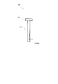
- the stomach wall can be fixed to the body wall with only one puncture needle, as shown in FIG. Became.
- the instrument of patent document 1 is a form (henceforth a repetitive type) in which a several suturing tool is accommodated in the inside of a puncture needle, and can be extruded separately. Specifically, four suture tools are accommodated in the puncture needle.
- Patent Document 2 describes an organ fixing device using a T-shaped suture tool.
- This instrument uses a suturing tool in which a looped suture thread is engaged with a rod-shaped locking portion (rod).
- This organ fixing tool is in a form in which only one suturing tool is provided inside the puncture needle (hereinafter referred to as a single shot type).
- a pad-shaped cushion material is attached to the suture thread. The cushion material is pressed against the body surface, and the suture loop is cut into a two-string state and then entangled with each other and tied to the cushion material. As a result, it is possible to fix to the body surface for each individual suturing tool at 3 to 4 fixing locations.
- the organ fixing device of Patent Document 1 has a problem that sutures tend to be entangled because all of the four sutures are inserted into the puncture needle. If the suture thread is entangled, there is a possibility that when the locking portion at the tip is pushed out from the puncture needle and the puncture needle is removed from the body wall, it is pulled out to another locking portion.
- the organ fixing tool of patent document 1 has the subject that a puncture needle is thick and highly invasive. That is, when the organ fixing device of Patent Document 1 accommodates four suture tools inside the puncture needle, four sutures are provided around the uppermost stage, that is, around the engaging portion that passes through the inside of the puncture needle on the extrusion device side. Yarns are distributed and arranged.
- the inner diameter of the puncture needle needs to be a dimension that is the sum of the thicknesses of two suture threads on both sides in addition to the outer diameter of the locking portion.
- the external diameter of the puncture needle is thicker in the organ fixing tool of Patent Document 1 than in the single-shot type that houses only one suture tool. Therefore, although the instrument of Patent Document 1 has a technical advantage due to the continuous type, there is a risk that the suture becomes entangled and difficult to operate, and there is a problem that the puncture needle is thick and highly invasive.
- the organ fixing tool of patent document 2 is a single shot type, one instrument is required for each fixation of the stomach wall and the body wall, and the replacement of the instrument is complicated and the cost is high. There are challenges.
- the present invention has been made in view of the above problems, and has a continuous-type merit that the exchange work such as discarding, opening, and changing the instrument is reduced and is simple, and the conventional continuous-type organ fixing device.
- the present invention provides an organ fixing device that improves the stability of the operation by suppressing the entanglement of the suture thread and can reduce the diameter of the puncture needle to realize minimally invasive.
- a plurality of suture tools comprising a rod-shaped locking portion and a suture thread coupled to the locking portion, and a puncture needle that houses a plurality of the locking portions And a plurality of the locking portions that are pushed out from the puncture needle one by one by operating the operation portion main body, wherein at least one of the plurality of locking portions
- a repetitive organ fixing device is provided in which a suture thread connected to a locking portion is inserted into the puncture needle, and another suture thread is led out from the inside of the puncture needle.
- a suturing tool comprising a rod-shaped engaging portion and a plurality of sutures having ends connected to the engaging portion, and a plurality of the engaging portions.
- a puncture needle which is stored side by side in the proximal direction, and is a repetitive organ fixing device in which the plurality of locking portions are pushed out from the puncture needle one by one by operation of the operation portion main body, A thread passage for inserting the suture thread of the suture tool housed in the inside of the puncture needle is formed in the locking portion of the other suture tool housed on the proximal end side.
- a repetitive organ fixing device is provided.
- the number of sutures passing through the puncture needle can be reduced. Therefore, there are provided a repetitive organ fixing device that can improve the stability of the operation based on the reduction of the entanglement of the suture thread inside the puncture needle and can prevent the outer diameter of the puncture needle from expanding.
- the suture can be inserted into the puncture needle through the thread passage formed in the locking portion.
- FIG. 6 is a cross-sectional view showing a state where the locking portion is engaged with the inside of the stomach wall in the organ fixing device according to the first embodiment of the first aspect.
- FIG. 2 shows a first embodiment of the first aspect, and is a cross-sectional view taken along the line AA of FIG.
- FIG. 2 is a cross-sectional view showing the first embodiment of the first aspect and taken along line BB in FIG. 1.
- FIG. 14 shows a second embodiment of the first aspect, and is a cross-sectional view along the line DD in FIG. 13.
- FIG. 14 shows a second embodiment of the first aspect, and is a cross-sectional view along the line DD in FIG. 13.
- FIG. 13 shows the organ fixing tool of 3rd embodiment of the 1st aspect of this invention.
- It is a partially expanded sectional view which shows the puncture needle of 3rd embodiment of a 1st aspect.
- sectional drawing which shows the organ fixing tool of 3rd embodiment of a 1st aspect.
- FIG. 6 is a cross-sectional view showing a state in which the locking portion is engaged with the inside of the stomach wall in the organ fixing device according to the first embodiment of the second aspect. It is sectional drawing which shows the organ fixing tool of the modification of 1st embodiment of a 2nd aspect.
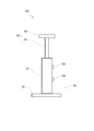
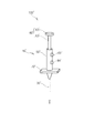
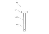
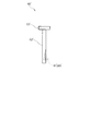
- FIG. 1 is a partial sectional view showing an organ fixing device according to a first embodiment of the first aspect of the present invention
- FIG. 2 is a schematic perspective view showing the organ fixing device
- FIG. 3 is a partial side view showing the organ fixing device.
- 4 is a partial perspective view showing the internal mechanism of the organ fixing device
- FIG. 5 is a side view showing the operation unit
- FIG. 6 is another side view showing the operation unit
- FIG. 7 is the operation unit of the first embodiment.
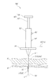
- FIG. 8 is a cross-sectional view showing a state in which the organ fixing tool is punctured in the abdomen
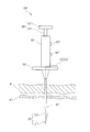
- FIG. 9 is a cross-sectional view showing a state in which the operation part of the organ fixing tool is lowered
- FIG. 11 is a cross-sectional view showing a state in which the locking portion is engaged with the inside of the stomach wall
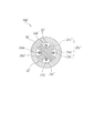
- FIG. 11 is a cross-sectional view taken along line AA in FIG. 1
- FIG. 12 is a cross-sectional view taken along line BB in FIG.
- the organ fixing tool 100 includes suture tools 20 and 20 a, a puncture needle 30, and an extrusion device 40 having an operation unit main body 63.
- the suture tools 20 and 20a are composed of rod-shaped locking portions 21 and 21a and sutures 22 and 22a connected to the locking portions 21 and 21a.
- the puncture needle 30 can accommodate at least a plurality of the locking portions 21 and 21a, for example, two in this embodiment.
- the push-out device 40 pushes a plurality of (for example, two) locking portions 21 and 21a from the puncture needle 30 one by one by operating the operation portion main body 63.
- the suture tools 20 and 20a are inserted into the puncture needle 30 with a part of suture threads 22a of a plurality of (for example, two) locking portions 21 and 21a as shown in FIG.
- the other suture thread 22 is led from the inside of the puncture needle 30 to the outside on the side surface in the axial direction of the puncture needle 30.
- the needle tip 31 side of the puncture needle 30 is referred to as the distal end side
- the side fixed to the pushing device 40 of the puncture needle 30 is referred to as the proximal end side.
- the suture tools 20 and 20a of the present embodiment will be described in detail.
- a plurality of, for example, two suturing tools 20, 20a are loaded in the organ fixing device 100 and used in a repetitive manner.
- the suture tools 20 and 20a include a first-stage suture tool 20 and a second-stage suture tool 20a located in the next stage in order from the needle tip 31 side of the puncture needle 30, that is, the distal end side of the puncture needle 30.
- the number of steps of the suture tool refers to the order viewed from the distal end side of the puncture needle 30.
- the locking portions 21 and 21a have a metal rod shape exemplified by stainless steel, for example, a cylindrical shape.
- One suture thread 22 and 22a is attached to one end of the suture thread 22 or 22a in the middle of the length of the locking parts 21 and 21a (in the axial direction), for example, at the center of the locking parts 21 and 21a. It is fixed, or is fixed by caulking around the locking portions 21 and 21a. The other ends of the sutures 22 and 22a are led out of the organ fixing device 100 through the inside or outside of the puncture needle 30.
- the puncture needle 30 is an injection needle made of a stainless steel cylinder. As shown in FIG. 1, the puncture needle 30 has a storage portion 32 into which the locking portions 21 and 21a can be inserted.
- the storage part 32 can store a plurality of, for example, two locking parts 21, 21 a along the axial direction of the puncture needle 30. One end of the storage portion 32 opens to the needle tip 31, and the other end communicates with the extrusion device 40.
- the storage part 32 is hollow, and its full length is set to be equal to or longer than two of the locking parts 21 and 21a.
- the inner diameter of the storage portion 32 that is, the inner diameter of the puncture needle 30 is equal to or greater than the first total length obtained by adding the short diameter of the suture thread 22, 22 a to the short diameter of the locking portions 21, 21 a, and It is less than the second total length obtained by adding the long diameter of two suture threads 22 and 22a to the long diameter of 21a.
- the inner diameter of the storage portion 32 that is, the inner diameter of the puncture needle 30, is equal to or greater than the first total length obtained by adding the minor diameter of the suture threads 22 and 22a to the minor diameter of the locking portions 21 and 21a.
- the total length is preferably less than the third total length obtained by adding the minor axis of the suture threads 22 and 22a to the total length.
- the major axis is defined as the diameter of a perfect circle (a circumscribed circle) having a minimum diameter that can include a circular shape, an elliptical shape, a polygonal shape, and the like, which are cross-sectional shapes of the puncture needle 30 or the locking portions 21 and 21a.
- the short diameter is defined as the diameter of the smallest perfect circle (inscribed circle) that can be included in the cross-sectional shape of the puncture needle 30 or the locking portions 21 and 21a, such as a circle, an ellipse, or a polygon.
- the short diameter and the long diameter when the cross-sectional shape of the suture thread is a perfect circle can be read as the diameter of the perfect circle.
- First total length ⁇ Inner diameter of puncture needle ⁇ Third total length Therefore, according to the organ fixing device 100 of the present embodiment, on both sides around the locking portion as in the instrument of Patent Document 1.
- the outer diameter of the puncture needle 30 can be reduced compared to the case where a plurality of sutures are passed through facing each other.
- FIG. 12 shows a state where the locking portions 21 and 21a and the sutures 22 and 22a are loosely inserted into the puncture needle 30, but the inner diameter of the puncture needle 30 is the first as described above. It is preferable that the total length is equal to or greater than the second total diameter, and more preferably equal to or greater than the first total length and less than the third total length.
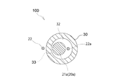
- the puncture needle 30 is provided with a penetrating portion that penetrates into and out of another suture tool, that is, the suture thread 22 of the first-stage suture tool 20, that is, a slit 33.
- the penetrating portion is a portion that becomes a path for inserting the suture thread 22 into and out of the puncture needle 30, and the side surface in the axial direction of the puncture needle 30 is penetrated inward and outward.
- the penetration part may be provided with the slit 33 as in the present embodiment, may be provided with a lateral hole (see the third embodiment), or may have both.
- the slit 33 extends from the needle tip 31 of the puncture needle 30 toward the operation portion main body 63.
- the slit 33 has one end opened to the needle tip 31, and the other end extends linearly along the axial direction of the puncture needle 30 toward the proximal end side of the puncture needle 30, that is, the pusher 40 side. Is terminated at the middle portion (the distal end side with respect to the proximal end portion of the puncture needle 30).
- the end position of the slit 33 that is, the position of the other end of the dead end needs to extend to the arrangement region of the suture thread 22 of the first-stage suture tool 20 in the state of being housed in the housing portion 32. However, it may be longer than this and may extend to the extrusion device 40 side (base end side).
- the groove width of the slit 33 is set to be equal to or greater than the thickness of one suture 22.
- one of the sutures 22 and 22a that is, the first-stage suture 22 passes through the outside of the puncture needle 30, Another one, that is, the second-stage suture thread 22a passes through the inside.
- the two suture threads 22 and 22a are separated into the inside and outside of the puncture needle 30 and their paths are completely different and do not cross each other, so that the two suture threads 22 and 22a can be completely prevented from being entangled.
- the extrusion device 40 is for performing a continuous operation. As shown in FIGS. 2 to 7, the extrusion device 40 is roughly composed of a cylindrical portion 50, an operation portion 60, a gripping portion 70, and a lock device 80.
- the cylindrical part 50 is a cylinder made of synthetic resin, and the puncture needle 30 is fixed as shown in FIGS. Both end portions of the tube portion 50 are open, and a proximal end portion of the puncture needle 30 opposite to the needle tip 31 is fixed to one end portion of the opening, and the inside of the tube portion 50 is inserted into the puncture device through the one end portion.
- the operation unit 60 is inserted into the inside from the other end of the opening in communication with the storage unit 32 of the needle 30.
- the tube portion 50 is provided with a yarn discharge hole 51 penetrating inward and outward. The suture thread 22 a led through the storage portion 32 of the puncture needle 30 and into the cylindrical portion 50 passes through the thread discharge hole 51.
- the operation unit 60 pushes the locking portions 21 and 21 a stored in the storage unit 32 of the puncture needle 30 through the inside of the tube unit 50 from the needle tip 31 of the puncture needle 30.
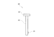
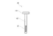
- the operation unit 60 is roughly composed of an extrusion rod 61, a pressing unit 62, and an operation unit main body 63.
- the push rod 61 is a stainless steel core rod that is inserted into the storage portion 32 of the puncture needle 30 from the inside of the tube portion 50 and slides in the storage portion 32 to store the push rod 61.
- the locking portions 21, 21 a stored in the portion 32 are pushed out from the needle tip 31. That is, in order from the needle tip 31, the first-stage locking portion 21 and the second-stage locking portion 21 a positioned in the next stage are accommodated in order, so that the push-out rod 61 has the second-stage locking portion. It contacts the part 21a.
- the push rod 61 advances to the needle tip 31 side (tip side of the puncture needle 30), it is pushed by the push rod 61 and the second-stage locking portion 21a advances to the needle tip 31 side. For this reason, it is pushed by the second stage locking part 21a, and the first stage locking part 21 also advances toward the needle tip 31 side.
- the pressing portion 62 is a synthetic resin cylinder, and as shown in FIG. 4, the push rod 61 is fixed to one end portion, and the other end portion reaches an operation portion main body 63 described later. The pressure is transmitted to the extrusion rod 61.
- the pressing portion 62 is slidably held inside the cylindrical portion 50 and protrudes to the outside of the cylindrical portion 50 from the other open end portion that opens upward in FIG.
- the operation part main body 63 is a disc shape made of synthetic resin, and is for performing a pressing operation as shown in FIGS. As shown in FIG. 2, the operation portion main body 63 protrudes in a disk shape from the upper end portion of the pressing portion 62 located on the upper side in the drawing.
- the outer diameter of the operation portion main body 63 is set to be larger than the inner diameter of the other open end of the cylindrical portion 50 that opens upward in the drawing so that the operating portion main body 63 is not accidentally fitted into the cylindrical portion 50.
- the gripping portion 70 is a flat plate made of synthetic resin and grips the extrusion device 40. As shown in FIG. 2, the gripping portion 70 projects symmetrically from the lower side of the cylindrical portion 50 toward the left and right sides in the same figure.
- the locking device 80 restricts the operation unit 60 from inadvertently sliding with respect to the cylinder unit 50.
- the locking device 80 is roughly composed of an engaging claw 81 and concave portions 82 and 82a.
- the cylinder part 50 is provided with release buttons 83 and 84 for releasing the lock state of the lock device 80.
- the engaging claw 81 prevents the operating portion 60 from being pressed against the tubular portion 50 by fitting into either of the recesses 82 and 82a.
- the engaging claw 81 is provided in the pressing portion 62 and protrudes in a convex shape from the outer periphery thereof.
- the pressing part 62 is formed in a cylindrical shape, and the outer peripheral walls on both sides sandwiching the engaging claw 81 are cut out. Thereby, the convex engaging claw 81 can be elastically bent into the inside of the cylinder of the pressing portion 62.
- the recesses 82 and 82a are provided in the cylindrical portion 50, and are provided in two upper and lower stages in the figure.
- the recesses 82 and 82a penetrate the inside and outside of the cylindrical portion 50, the engaging claw 81 is fitted from the inner peripheral side of the cylindrical portion 50, and release buttons 83 and 84 to be described later are attached to the outer peripheral side.
- the tip of the push rod 61 is stored in the storage portion 32 of the puncture needle 30 as shown in FIG. It faces the eye, that is, the locking portion 21a located on the upper side in the figure.
- the operation portion 60 is further prevented from being pushed into the cylindrical portion 50, and the suture tools 20, 20 a are inserted into the needle tip of the puncture needle 30. Extrusion from 31 is prevented. Further, the operation unit 60 is also restricted from coming out of the tube unit 50.
- the engaging claw 81 fitted in the concave portion 82 located on the upper side advances toward the concave portion 82a located on the lower side in FIG. 4, the second locking portion 21a is pushed by the push rod 61. Proceed to the needle tip 31 side. For this reason, the first-stage locking portion 21 is pushed by the second-stage locking portion 21 a and pushed out from the needle tip 31.
- the engaging claw 81 is fitted into the concave portion 82a located on the lower side.
- the operation portion 60 is further prevented from being pushed into the cylindrical portion 50, and the second-stage suture tool 20a is inserted into the puncture needle 30. It is prevented that the needle tip 31 is pushed out.
- the release buttons 83 and 84 are button-shaped protrusions made of synthetic resin or the like. As shown in FIG. 4, the release buttons 83 and 84 are configured so that the engaging claw 81 fitted into one of the recesses 82 and 82 a is moved from the inside of the recesses 82 and 82 a toward the inside of the cylinder part 50, that is, the cylinder part. Push radially inward toward the center of 50. As a result, the engaging claw 81 is disengaged from the recesses 82 and 82a, and the locked state is released. As shown in FIG.
- the release buttons 83 and 84 are fitted into the upper and lower recesses 82 and 82a from the outer peripheral side of the cylindrical portion 50, and project from the outer periphery by a spring force of a leaf spring or a coil spring, although not shown.
- the organ fixing device 100 is used as an initial state in which the engaging claw 81 is fitted in the concave portion 82 located on the upper side in FIG.
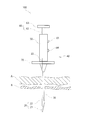
- the puncture needle 30 is punctured from outside the patient's body until it penetrates the skin side wall A and the stomach wall B, and the needle tip 31 is exposed in the stomach cavity.
- the release button 83 located on the upper side in FIG. When the release button 83 is pressed, the engagement claw 81 fitted in the concave portion 82 located on the upper side in the figure is disengaged, and the lock state of the lock device 80 is released. Then, the operation part main body 63 is pressed toward the inside of the cylinder part 50, as shown in FIG.
- the push rod 61 advances in the storage portion 32 of the puncture needle 30, and the first-stage locking portion 21 is pushed out from the needle tip 31 via the second-stage locking portion 21a. .
- the first stage locking portion 21 is introduced into the stomach cavity as shown in FIG.
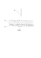
- the organ fixing device 100 collects the puncture needle 30 by pulling it out of the body.
- the locking portion 21 pulls the stomach wall B toward the skin side wall A by pulling the suture thread 22 of the locking portion 21 at the first stage from the outside of the body. Thereafter, the stomach wall B is fixed to the skin side wall A by fixing the suture thread 22 to the outside of the body.
- the collected puncture needle 30 of the organ fixing device 100 is punctured from a different position of the skin side wall A until it penetrates the stomach wall B to expose the needle tip 31 in the stomach.
- the release button 84 located on the lower side in FIG. 4 is pressed.
- the engagement claw 81 fitted in the concave portion 82a located on the lower side in FIG. 3 is engaged and disengaged, and the lock state of the lock device 80 is released.
- the operation portion main body 63 is pressed toward the inside of the cylindrical portion 50.
- the push rod 61 advances in the storage portion 32 of the puncture needle 30, and the second-stage locking portion 21 a is pushed out from the needle tip 31. For this reason, the second locking portion 21a is introduced into the stomach cavity.
- the stomach wall B is fixed to the skin side wall A by pulling and fixing the suture thread 22a of the second-stage locking portion 21a from outside the body similarly to the first-stage suture thread 22.
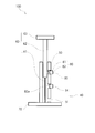
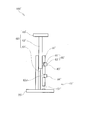
- ⁇ Second embodiment> 13 is a partial cross-sectional view showing an organ fixing device according to a second embodiment of the first aspect of the present invention
- FIG. 14 is a cross-sectional view taken along the line CC of FIG. 13, and FIG. It is sectional drawing which follows a D line.
- the organ fixing device 100 of the present embodiment is different from the first embodiment in that the number of the suturing devices 20, 20a to 20c is increased.
- the organ fixing device 100 of the present embodiment is different from the first embodiment in that the slit 200 is extended.
- suture tools 20, 20a to 20c are loaded. That is, four locking portions 21, 21 a to 21 c are stored in the storage portion 32 of the puncture needle 30.
- the sutures 22, 22a of the two suture tools 20, 20a are led out from the inside of the puncture needle 30 to the outside. . That is, of the four suture threads 22 and 22a to 22c of the present embodiment, two first-stage and second-stage suture threads 22 and 22a are outside the puncture needle 30, and the remaining two, or third-stage sutures.
- the fourth-stage suture threads 22b and 22c pass through the inside of the puncture needle 30 (the storage portion 32).
- Adjacent sutures 22, 22a to 22c are spaced apart in the outer peripheral direction of the puncture needle 30, and are arranged at equal intervals, that is, at intervals of 90 degrees.
- the slit 200 is an arrangement region of the locking portion 21 located on the distal end side (first stage) of the puncture needle 30 on the assumption that there are three or more suture tools 20, 20a to 20c (four in this embodiment). From at least halfway through the arrangement region of the locking portion 21a located at the next stage (second stage).
- the suture thread of the latching section 21a located on the next stage (second stage). 22a can be inserted. That is, the suture thread 22 of the first-stage locking portion 21 and the suture thread 22a of the second-stage locking portion 21a loaded in the puncture needle 30 are drawn out through the slit 200.
- the slit 200 has one end opened to the needle tip 31, and the other end extends linearly along the axial direction of the puncture needle 30 to the proximal end side of the puncture needle 30, that is, the extrusion device 40 side. Is formed.
- the position of the other end of the dead end needs to extend to the arrangement region of the suture thread 22a of the second-stage suture tool 20a stored in the storage unit 32, but is longer than this,
- the puncture needle 30 may extend to the proximal end side (the extrusion device 40 side).
- the slit 200 may form a wide opening along the outer periphery of the puncture needle 30. For example, in FIG.
- the slit 200 is formed as an opening of about 1 ⁇ 4 of the outer periphery of the puncture needle 30.
- the first-stage suture 22 is led out of the puncture needle 30 from the storage portion 32 along one end of the circumferential opening of the slit 200
- the second-stage suture 22 a is Along the other end of the puncture needle 30 in the circumferential direction
- the puncture needle 30 is led out of the puncture needle 30 from the storage portion 32.
- the first stage suture thread 22 and the second stage suture thread 22a are different from each other by about 90 degrees, and the suture thread 22 and the suture thread 22a are separated from each other and led to the outside of the puncture needle 30. And entanglement of the suture can be reduced.
- ⁇ Third embodiment> 16 is a partial cross-sectional view showing an organ fixing device according to a third embodiment of the first aspect of the present invention
- FIG. 17 is a partial enlarged cross-sectional view showing a puncture needle
- FIG. 18 is a cross-sectional view showing the puncture needle. is there.
- the organ fixing device 100 of the present embodiment is different from the first embodiment in that the number of the suturing devices 20, 20a to 20c is first increased as in the second embodiment. 2ndly, the organ fixing tool 100 of this embodiment is different from 1st and 2nd embodiment by the point which provided the horizontal hole 300 as a penetration part.
- suturing tools 20, 20a to 20c are loaded as shown in FIG. 16, as in the second embodiment. That is, four locking portions 21, 21 a to 21 c are stored in the storage portion 32 of the puncture needle 30.
- the puncture needle 30 is provided with a lateral hole 300 penetrating inward and outward. Any one of the suture threads 22 and 22a to 22c of the locking portions 21 and 21a to 21c stored in the storage portion 32 is led out of the puncture needle 30 through the horizontal hole 300, whereby the horizontal hole 300 penetrates. It functions as a part.
- one horizontal hole 300 is formed in a circular shape in a side view, and the inner diameter is set to be equal to or larger than the thickness of the suture thread 22b.
- the lateral hole 300 is located in the arrangement region of the suture thread 22b of the third-stage suture tool 20b accommodated in the accommodating portion 32, and the suture thread 22b is led out of the puncture needle 30 through the hole. .
- the end face on the distal end side of the horizontal hole 300 is inclined toward the inner distal direction (from the inner side toward the outer side, toward the proximal direction). That is, an inclined portion 310 is formed on the end face on the distal end side of the horizontal hole 300, and the surface of the inclined portion 310 is formed so as to be directed to the inner side (lumen) of the puncture needle 30.
- the inclined portion 310 is in sliding contact with the third-stage suture thread 22b to reduce frictional resistance. That is, when the third-stage locking portion 21b stored in the storage portion 32 advances toward the needle tip 31 side of the puncture needle 30, the suture thread 22b comes into sliding contact with the inclined portion 310.
- the sutures 22 and 22b of the two suture tools 20 and 20b led out from the inside of the puncture needle 30 are opposed to each other with the puncture needle 309 interposed therebetween.
- the lateral hole 300 is arranged so as to be 180 degrees out of phase with the slit 33, that is, to face the puncture needle 30.
- the suture thread 22 of the first-stage locking portion 21 is led out from the inside of the puncture needle 30 through the slit 33.
- the suture thread 22b of the third locking portion 21b is led out from the inside of the puncture needle 30 through the lateral hole 300.
- the slit 33 and the lateral hole 300 are in the circumferential direction of the puncture needle 30. Since the 180-degree phase is different, the first-stage suture thread 22 and the third-stage suture thread 22b are opposed to each other with the puncture needle 30 interposed therebetween.
- FIG. 19 is a partial side view showing the organ fixing device according to the fourth embodiment of the first aspect of the present invention.
- the organ fixing device 100 of this embodiment is different from the first and second embodiments in that the slit 400 is formed on the surface of the puncture needle 30 in a non-linear manner with respect to the axis.
- the slit 400 is a modification of the extended slit 200 shown in FIGS. 13 and 14 of the second embodiment.
- the number of the suturing tools 20, 20a to 20c is three or more, for example, four. As shown in FIG. 19, it is formed non-linearly.
- the slit 400 has one end opened to the needle tip, and the other end extends linearly halfway in the axial direction of the puncture needle 30, that is, upward in the figure, as shown in FIG. After that, the other end portion of the slit 400 is bent in an arc shape, and the end portion is linearly extended upward to form a dead end.
- the slit 400 includes two linear slits that are linear in the axial direction and spaced apart from each other, and a slit that communicates the two linear slits, and these slits are formed integrally. It is.
- the position of the other end of the dead end is the same as that of the slit 200 of the second embodiment. Referring to FIG. 13, it is necessary to extend to the arrangement region of the suture thread 22 a of the second-stage suture tool 20 a stored in the storage portion 32. You may extend over the apparatus 40 side.
- the slit 400 may be formed in a spiral shape in the circumferential direction of the puncture needle 30.
- the first-stage suture thread 22 and the second-stage suture thread 22a are 90 degrees out of phase with each other. 13 can be led out of the puncture needle 30.
- FIG. 20 is a schematic perspective view showing the organ fixing device 100 according to the fourth embodiment of the first aspect of the present invention.
- the organ fixing device 100 according to the present embodiment is different from the first embodiment in that the number of the concave portions 500 to 503 is increased and the cylindrical portion 50 is arranged at different positions in the circumferential direction.
- the recesses 500 to 503 penetrate through the inside and outside of the cylinder portion 50, and the engagement claws 81 of the operation portion 60 are fitted therein.
- the engaging claw 81 has the same structure as that of the first embodiment already described with reference to FIGS. 5 to 7, and its convex portion is fitted into any one of the concave portions 500 to 503. When protruding from the outer periphery of the cylindrical portion 50, it can be pressed.
- a total of four recesses 500 to 503 are formed on the premise that two suture tools 20 and 20a are loaded. Of the four recesses 500 to 503, the two first and second recesses 500 and 501 are arranged apart from each other in FIG.
- the distance between the first and second recesses 500 and 501 is made to correspond to the stroke required to push out the first-stage locking portion 21 located on the needle tip 31 side, as described with reference to FIG.
- the remaining two third and fourth recesses 502 and 503 are displaced in the outer peripheral direction of the cylindrical portion 50 and are spaced apart in the vertical direction in FIG. 20.
- the third recess 502 positioned on the upper side in FIG. 20 is positioned at the same height as the second recess 501 positioned on the lower side.
- the fourth recessed portion 503 located on the lower side is located away from the third recessed portion 502 downward. If the space
- the locking portions 21 and 21a are columnar, but may be hollow cylinders, or the cross-sectional shape is not limited to a circle but may be a polygon.
- one suture thread 22, 22a is used for each of the locking portions 21, 21a.
- a plurality of two suture threads may be used.
- the sutures 22 and 22a are fixed to the centers of the locking portions 21 and 21a.
- the sutures 22 and 22a may be one end of the locking portions 21 and 21a, or a single suture may be looped.
- the first-stage suture 22 is taken outside the puncture needle 30 and the second-stage suture 22a is taken inside, but the first-stage suture 22 is taken inside the puncture needle 30,
- the stage suture thread 22a may pass through the outside.
- the operation portion main body 63 is formed in a disc shape, but may be formed in a rod shape.
- the grip portion 70 is formed in a flat plate shape, but may be formed in a ring shape or a lever shape. Further, the gripping part 70 may be formed integrally with the cylinder part 50 or may have a separate structure.
- the number of the suture tools 20 and 20a is two, and in the second embodiment, the number of the suture tools 20, 20a to 20c is four, but may be three or five or more.
- the two first and second sutures 22, 22a pass through the outside of the puncture needle 30, and the remaining two, Third-stage and fourth-stage suture threads 22b and 22c pass through the inside.
- the first and third-stage sutures 22 and 22b may pass through the outside
- the second and fourth-stage sutures 22a and 22c may pass through the inside.
- the first and fourth stage sutures 22 and 22c may pass through the outside of the puncture needle 30, and the second and third stage sutures 22a and 22b may pass through the inside.
- the adjacent sutures 22 and 22a to 22c are arranged at intervals of 90 degrees.
- the present invention is not limited to this, and the adjacent sutures 22 and 22a to 22c are 180 with the puncture needle 30 interposed therebetween. You may make it oppose position.
- the second embodiment if only three suture tools 20, 20a to 20b are used instead of the four suture tools 20, 20a to 20c, the three suture threads 22, 22a to 22b are used.
- two sutures may pass outside the puncture needle 30 and the remaining one may pass inside the puncture needle 30; two sutures pass inside the puncture needle 30 and one remaining May pass through the outside of the puncture needle 30, but it is preferable that two sutures pass through the outside of the puncture needle 30 and the remaining one passes through the inside of the puncture needle 30.
- the slit 33 and the horizontal hole 300 are provided as the penetrating portion.
- the slit 33 may be omitted and only the horizontal hole 300 may be formed.
- a plurality of lateral holes 300 may be provided.
- the lateral hole 300 may be formed in an elliptical shape, an oval shape, or a polygonal shape as well as the circular shape in the side view illustrated.
- the horizontal hole 300 and the slit 33 are arranged with a phase difference of 180 degrees.
- the horizontal hole 300 and the slit 33 are not limited to 180 degrees in the sense that the sutures 22, 22a to 22c are less likely to be entangled.
- the concave and convex portions that are fitted to each other are formed on the end surfaces of the two adjacent locking portions, and adjacent to each other.
- the relative rotation around the axis of the locking portion may be restricted.
- the above embodiment includes the following technical idea.
- (1) It has a rod-shaped locking part, a suture thread connected to the locking part, a plurality of suture tools, and a puncture needle that houses a plurality of the locking parts.
- a repetitive organ fixing device in which the plurality of locking portions are pushed out one by one from the puncture needle by operation of a main body, and sutures connected to at least one locking portion among the plurality of locking portions
- a repetitive organ fixing device characterized in that a thread is inserted into the puncture needle and another suture thread is led out from the inside of the puncture needle.
- (2) The repetitive organ fixing device according to (1), wherein the puncture needle is provided with a penetrating portion penetrating inward and outward through which the other suture thread passes.
- the repetitive organ fixing device according to (4) which is less than the second total length including the major axis of the minute.
- the number of the suturing tools is three or more, and the slits are arranged on the locking portion located at the next stage on the proximal end side of the puncture needle from the arrangement region of the locking portion located on the distal end side of the puncture needle.
- the repetitive organ fixing device according to the above (3) which extends at least partway in the arrangement region and is inserted through the slit with a suture thread of a locking portion located in the next stage.
- the continuous organ fixing device according to (6) wherein the slit is formed in a spiral shape.
- the number of the suturing tools is three or more, and among the three or more suturing sutures, the sutures of two suturing tools are led out from the inside of the puncture needle to the puncture needle.
- the repetitive organ fixing device according to any one of (1) to (3), (6), and (7), which are arranged to face each other.
- FIG. 21 shows the organ fixing device according to the first embodiment of the second aspect of the present invention.
- FIG. 21 is a sectional view taken along the line A′-A ′ of FIG.
- FIG. 22 is a partial cross-sectional view showing an organ fixing device.
- 23 is a schematic perspective view showing the organ fixing tool
- FIG. 24 is a partial side view showing the organ fixing tool
- FIG. 25 is a partial perspective view showing the internal mechanism of the organ fixing tool
- FIG. 26 is a side view showing the operation unit.
- 27 is another side view showing the operation unit
- FIG. 28 is a side view showing a state in which the engaging claw of the operation unit is pushed in.
- FIG. 29 is a cross-sectional view showing a state where the organ fixing tool is punctured in the abdomen
- FIG. 30 is a cross-sectional view showing a state where the operation part of the organ fixing tool is lowered
- FIG. 31 is a state where the locking part is engaged with the inside of the stomach wall.
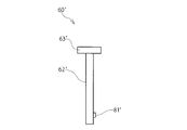
- the organ fixing device 100 ′ includes suture tools 20 ′ and 20a ′ to 20c ′, a puncture needle 30 ′, and an extruding device 40 ′ having an operation portion main body 63 ′.
- the suture tools 20 ′ and 20a ′ to 20c ′ are connected to the rod-like locking portions 21 ′ and 21a ′ to 21c ′ and the locking portions 21 ′ and 21a ′ to 21c ′.
- the suture thread 22 'and 22a' to 22c ' are connected to each other.
- a plurality of puncture needles 30 ′ for example, four locking portions 21 ′ and 21a ′ to 21c ′ in the present embodiment, are arranged side by side in the direction of the proximal end.
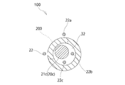
- the extrusion device 40 ′ provided in the repetitive organ fixing device 100 ′ of the present embodiment allows a plurality of (for example, two) locking portions 21 ′ and 21a ′ to be moved from the puncture needle 30 ′ by operating the operation portion main body 63 ′. Extrude one by one. As shown in FIG.
- ⁇ 23d ′ are formed in the locking portions 21a′ ⁇ 21c ′ of the other suture tools 20a′ ⁇ 20c ′ housed on the base end side.
- the needle tip 31 ′ side of the puncture needle 30 ′ is referred to as the distal end side
- the side fixed to the pushing device 40 ′ of the puncture needle 30 ′ is referred to as the proximal end side.
- the direction from the proximal end side to the distal end side may be referred to as an extrusion direction.
- suture tools 20 ′ and 20a ′ to 20c ′ of this embodiment will be described in detail.
- a plurality of, for example, four suturing devices 20 ′, 20a ′ to 20c ′ are loaded into the organ fixing device 100 ′ and used in a repetitive manner.
- the suture tools 20 ′, 20a ′ to 20c ′ are arranged in order from the needle tip 31 ′ side of the puncture needle 30 ′, that is, from the distal end side of the puncture needle 30 ′, and the second-stage suture tool 20a ′.
- a third-stage suture tool 20b 'and a fourth-stage suture tool 20c' are third-stage suture tool 20b 'and a fourth-stage suture tool 20c'.
- the locking portions 21 ′, 21a ′ to 21c ′ of the present embodiment are in the shape of a rod made of a metal such as stainless steel, for example, a cylindrical shape.
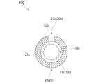
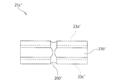
- thread passages 23a ′ to 23d ′ are formed around the locking portions 21 ′ and 21a ′ to 21c ′, that is, around the locking portion 21c ′ of the fourth-stage suture tool 20c ′. Yes.
- the yarn passages 23a ′ to 23d ′ of the present embodiment are formed in a groove shape on the peripheral surface of the locking portion 21c along the pushing direction of the locking portion 21c ′. Yes. That is, the yarn passages 23a ′ to 23d ′ are cut into a semicircular groove shape that is recessed from the peripheral surface of the locking portion 21c ′ toward the axial center of the locking portion 21c ′.
- the locking portion 21c ′ positioned at the fourth level has been described as an example, but the locking portions 21 ′, 21a ′, and 21b ′ positioned at the first level to the third level are also described. It has the same structure.
- the width dimension of the thread passages 23a 'to 23d' of this embodiment shown in FIG. 21 is equal to or larger than the diameters of the suture threads 22 'and 22a' to 22c '.
- the width dimension of the thread passages 23a 'to 23d' is the dimension of the thread paths 23a 'to 23d' viewed in the circumferential direction of the storage portion 32 'of the puncture needle 30'.
- the depths of the thread passages 23a 'to 23d' can be equal to or larger than the diameters of the suture threads 22 'and 22a' to 22c '.
- the depths of the yarn passages 23a 'to 23d' are the dimensions of the yarn passages 23a 'to 23d' seen in the radial direction of the storage portion 32 'of the puncture needle 30'.
- the depth of the thread passages 23a ′ to 23d ′ is equal to or greater than the diameter of the suture threads 22 ′ and 22a ′ to 22c ′, the protrusions of the suture threads 22 ′ and 22a ′ to 22c ′ from the periphery of the locking portion 21c ′ As a result, the suture threads 22 'and 22a' to 22c 'can be accommodated in the thread passages 23a' to 23d '.
- the difference (gap size) between the inner diameter of the storage portion 32 ′ and the diameter of the portion of the locking portion 21c ′ excluding the thread passages 23a ′ to 23d ′ is the two suture threads 22 ′ and 22a ′ to 22c ′.
- the depth of the thread passages 23a ′ to 23d ′ is less than the diameter of the suture threads 22 ′ and 22a ′ to 22c ′, that is, shallower, the suture threads 22 ′ and 22a ′ from the periphery of the locking portion 21c ′. A part of ⁇ 22c ′ protrudes. For this reason, it is preferable that the depth of the thread passages 23a 'to 23d' is deep, but even if it is shallower than this, the puncture needle 30 'contributes to reducing the diameter (see the modification shown in FIG. 32).
- each thread path (23a ′ to 23d ') can be set to 1/2 the diameter of the sutures 22', 22a'-22c '.
- each of the suture threads 22 ', 22a' to 22c ' protrudes from the thread passages 23a' to 23d 'by a half (radius) of the diameter.
- the diameter of the circumscribed circle that includes all of the sutures 22 'and 22a' to 22c ' is equal to the diameter of one of the suture threads 22' and 22a 'to 22c' in addition to the diameter of the locking portion 21 '. It can be suppressed to just a small diameter. For this reason, the diameter of the puncture needle 30 'is reduced to realize a minimally invasive organ fixing device 100'.
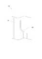
- FIG. 32 is a cross-sectional view showing a puncture needle 30 'according to a modification.
- the width dimension and depth of the thread passages 23a 'to 23d' may be less than the diameters of the suture threads 22 'and 22a' to 22c '.
- this modification only a part on the inner diameter side of the suture threads 22 ′, 22a ′ to 22c ′ is accommodated in the thread passages 23a ′ to 23d ′, and the outer diameters of the suture threads 22 ′, 22a ′ to 22c ′.
- the side is located outside the locking portion 21c ′.
- the concave shapes of the thread passages 23a 'to 23d' are arcuate shapes along the outer peripheral surfaces of the suture threads 22 'and 22a' to 22c '.
- the difference between the inner diameter of the storage portion 32 ′ and the diameter of the locking portion 21c ′ passing through the deepest portions of the opposing thread passages 23a ′ and 23c ′ is slightly smaller than the sum of the diameters of the sutures 22 ′ and 22b ′. Big.
- the difference between the inner diameter of the storage portion 32 ′ and the diameter of the portion of the locking portion 21c ′ excluding the thread passages 23a ′ to 23d ′ is smaller than the sum of the diameters of the suture threads 22 ′ and 22b ′.
- the difference between the inner diameter of the storage portion 32 ′ and the diameter of the locking portion 21c ′ passing through the deepest portions of the opposing thread passages 23b ′ and 23d ′ is the sum of the diameters of the sutures 22a ′ and 22c ′. Slightly larger than.
- the difference between the inner diameter of the storage portion 32 ′ and the diameter of the portion of the locking portion 21c ′ excluding the thread passages 23a ′ to 23d ′ is smaller than the sum of the diameters of the sutures 22a ′ and 22c ′. The same applies to the locking portions 21 ', 21a', 21b '.
- the suture threads 22 ′ and 22a ′ to 22c ′ are threaded through the thread passages 23a ′ to 23d ′ when the locking portions 21 ′, 21a ′ to 21c ′ are pushed out in order. They will not drop out of their engaged state, and will not be entangled with each other.
- a plurality of, for example, four yarn paths 23a 'to 23d' according to this embodiment are formed.
- the four thread passages 23a 'to 23d' are distributed and formed inside the puncture needle 30 'so as to be separated from each other.
- the four yarn passages 23a 'to 23d' of the present embodiment are dispersedly arranged around the locking portion 21 '(locking portion 21c') at equal intervals.
- the locking portion 21c ′ (see FIG. 22) positioned at the fourth level has been described as an example, but the locking portions 21 ′ and 21a ′ positioned at the other first to third levels, respectively. , 21b 'has a similar structure.
- the first locking portion 21 ′ in order from the needle tip 31 ′ side of the puncture needle 30 ′ is sufficient if there is one thread passage through which its own suture thread 22 ′ passes, but there are two thread passages. You may provide above.
- the second-stage locking portion 21a ′ is sufficient if there are two thread paths in total, through which the first-stage suture thread 22 ′ passes, in addition to one thread-passage path through its own suture thread 22a ′.
- three or more yarn passages may be provided.
- the third-stage locking portion 21b ′ includes a total of three passages through which the first-stage and second-stage suture threads 22 ′ and 22a ′ pass in addition to one thread passage through which the own suture thread 22b passes. It is sufficient if there is a yarn passage, but four or more yarn passages may be provided. As shown in FIG.
- the fourth-stage locking portion 21c ′ includes, in addition to one thread passage 23c ′ through which its own suture thread 22c ′ passes, the first-stage to third-stage suture threads 22 ′ and 22a ′. , 22b ′, a total of four yarn passages 23a ′ to 23d ′ are sufficient, but five or more yarn passages may be provided.
- the four thread passages 23a ′ to 23d ′ are uniformly distributed inside the puncture needle 30 ′. That is, the four yarn passages 23a ′ to 23d ′ are formed at intervals of 90 degrees.
- the locking portion 21c ′ positioned at the fourth level has been described as an example, but the locking portions 21 ′, 21a ′, and 21b ′ positioned at the first level to the third level are also described. It has the same structure.
- the same number of thread passages 23a ′ to 23d ′ as the number (4) of all the sutures 22 ′ and 22a ′ to 22c ′ include the locking portions 21 ′ and 21a ′. To 21c ′.
- the locking portions 21 'and 21a' to 21c 'can have the same shape, which contributes to a reduction in the number of parts.
- the suture threads 22 ', 22a' to 22c 'of the present embodiment are made of resin such as nylon.
- One suture thread 22 'and 22a' to 22c ' is provided for each of the locking portions 21' and 21a 'to 21c'.
- One end of each of the suture threads 22 ′, 22a ′ to 22c ′ is heated in the middle of the length of the locking portions 21 ′ and 21a ′ to 21c ′, for example, at the center of the locking portions 21 ′ and 21a ′ to 21c ′. It is fixed by fusing or bonding, or is fixed by caulking around the locking portions 21 ′, 21a ′ to 21c ′.
- the other ends of the sutures 22 'and 22a' to 22c ' are led out of the organ fixing device 100'.
- the puncture needle 30 ' is an injection needle made of a metal cylinder such as stainless steel. As shown in FIG. 22, engaging portions 21 ′ and 21a ′ to 21c ′ are accommodated in the accommodating portion 32 ′ inside the puncture needle 30 ′ so as to be freely inserted.
- the storage portion 32 ′ is hollow, and its entire length is set to be equal to or longer than the length of the four locking portions 21 ′ and 21a ′ to 21c ′. That is, the storage portion 32 ′ can store a plurality of, for example, four locking portions 21 ′ and 21a ′ to 21c ′ along the axial direction of the puncture needle 30 ′.
- One end of the storage portion 32 ′ is opened at the needle tip 31 ′, and the other end is communicated with the extrusion device 40 ′.
- the diameter of the storage portion 32 that is, the inner diameter of the puncture needle 30 ′ is slightly larger than the diameters of the locking portions 21 ′ and 21a ′ to 21c ′ as shown in FIG.
- the extrusion device 40 ′ is for performing a continuous operation.
- description will be given by taking as an example a case in which two suture tools 20 ′ and 20a ′ are loaded and sequentially sent out.
- the extrusion device 40 ′ is roughly composed of a cylinder portion 50 ′, an operation portion 60 ′, a gripping portion 70 ′, and a lock device 80 ′.
- the cylindrical part 50 ' is a cylinder made of synthetic resin, and the puncture needle 30' is fixed as shown in FIGS. Both ends of the cylindrical portion 50 ′ are open, and a proximal end portion of the puncture needle 30 ′ opposite to the needle tip 31 ′ is fixed to one end portion of the opening, and the cylindrical portion 50 ′ is connected to the cylindrical portion 50 ′ via the one end portion.
- the inside communicates with the storage portion 32 ′ of the puncture needle 30 ′, and the operation portion 60 ′ is inserted into the inside from the other end of the opening.
- the tube portion 50 ' is provided with a yarn output hole 51' penetrating inward and outward.
- the thread discharge hole 51 ′ is led out from the inside of the storage portion 32 of the puncture needle 30 ′ to the inside of the tube portion 50 ′ through the thread passages 23a ′ to 23d ′ of the locking portions 21 ′ and 21a ′.
- the two suture threads 22 'and 22a' passed through.
- the operation part 60 ′ passes through the inside of the cylinder part 50 ′ and pushes the locking parts 21 ′ and 21a ′ accommodated in the accommodation part 32 ′ of the puncture needle 30 ′ from the needle tip 31 ′ of the puncture needle 30 ′.
- the operation portion 60 ' is roughly composed of an extrusion rod 61', a pressing portion 62 ', and an operation portion main body 63'.
- the extrusion rod 61 ' is a metal core rod such as stainless steel. As shown in FIGS. 25 and 29, the push rod 61 ′ is inserted into the storage portion 32 ′ of the puncture needle 30 ′ from the inside of the cylindrical portion 50 ′, and slides in the storage portion 32 ′, thereby allowing the storage portion 32 to slide. 'The locking portions 21' and 21a 'housed in the inner side are pushed out from the needle tip 31'. That is, in the storage portion 32 ′, the first locking portion 21 ′ and the second locking portion 21a ′ located in the next stage are stored in order from the needle tip 31 ′. The push rod 61 ′ abuts on the second stage locking portion 21a ′.
- the pressing portion 62 ' is a synthetic resin cylinder. As shown in FIG. 25, an extrusion rod 61 'is fixed to one end of the pressing portion 62'. The other end of the pressing portion 62 ′ reaches an operation portion main body 63 ′ described later, and transmits the pressing force of the operation portion main body 63 ′ to the push rod 61 ′.
- the pressing portion 62 ′ is slidably held inside the cylindrical portion 50 ′, and protrudes to the outside of the cylindrical portion 50 ′ from the other end of the opening that opens upward in FIG.
- the operation unit main body 63 ′ is a disc shape made of synthetic resin, and is used for performing a pressing operation as shown in FIGS. 25 to 28. As shown in FIG. 23, the operation portion main body 63 'projects in a disk shape from the upper end portion of the pressing portion 62' positioned on the upper side in the drawing. The outer diameter of the operation portion main body 63 'is set to be larger than the inner diameter of the other open end of the cylindrical portion 50' that opens upward in the drawing so that it does not accidentally fit into the cylindrical portion 50 '.
- the gripping part 70 ′ is a flat plate made of synthetic resin and grips the extrusion device 40 ′. As shown in FIG. 23, the gripping part 70 'projects symmetrically from the lower side of the cylinder part 50' toward the left and right sides in the same figure.
- the locking device 80 ′ is a means for restricting the operation unit 60 ′ from inadvertently sliding with respect to the cylinder unit 50 ′. As shown in FIG. 25, the locking device 80 'is roughly composed of an engaging claw 81' and concave portions 82 'and 82a'. In addition, the cylinder portion 50 'is provided with release buttons 83' and 84 'for releasing the lock state of the lock device 80'.
- the engaging claw 81 ′ is fitted into one of the recesses 82 ′ and 82 a ′, thereby preventing the operation portion 60 ′ from being pressed against the cylinder portion 50 ′.
- the engaging claw 81 ′ is provided on the pressing portion 62 ′ and protrudes from the outer periphery thereof in a convex shape. Since the pressing portion 62 ′ is formed in a cylindrical shape, the convex portion can be elastically bent into the cylinder by cutting out the outer peripheral wall thereof.
- the concave portions 82 ′ and 82a ′ are provided in the cylindrical portion 50 ′, and are provided in two upper and lower stages in the figure.
- the recesses 82 ′ and 82a ′ penetrate inside and outside the cylinder portion 50 ′, and engaging claws 81 ′ are fitted from the inner peripheral side of the cylinder portion 50 ′, and release buttons 83 ′ and 84 described later are provided on the outer peripheral side. 'Is attached to each.
- the engaging claw 81 ′ is fitted in the concave portion 82 ′ located on the upper side in FIG. 24
- the distal end portion of the push rod 61 ′ is located in the accommodating portion 32 ′ of the puncture needle 30 ′ as shown in FIG.
- the second stage housed in the housing that is, the engaging portion 21a 'located on the upper side in the figure.
- the operating portion 60 ′ is further prevented from being pushed into the cylindrical portion 50 ′, and the suture tools 20 ′ and 20 a ′ are prevented. Is prevented from being pushed out from the needle tip 31 'of the puncture needle 30'. Further, the operation portion 60 ′ is prevented from coming off from the inside of the tube portion 50 ′.
- the release buttons 83 ′ and 84 ′ are made of synthetic resin, and as shown in FIG. 25, the engaging claws 81 ′ fitted into any of the recesses 82 ′ and 82 a ′ are connected to the recesses 82, 82a ′ is pushed inward in the radial direction toward the inside of the cylinder 50 ′, that is, toward the center of the cylinder 50 ′. As a result, the engaging claw 81 ′ is disengaged from the recesses 82 ′ and 82a ′, and the locked state is released. As shown in FIG. 25, the release buttons 83 ′ and 84 ′ are fitted into the upper and lower recesses 82 ′ and 82 a ′ from the outer peripheral side of the cylindrical portion 50 ′. Protrude from.
- the organ fixing tool 100 ′ is used in a state where the engaging claw 81 ′ is fitted in the concave portion 82 ′ positioned on the upper side in FIG.
- the puncture needle 30 ′ is punctured from outside the patient's body until it penetrates the body wall (abdominal wall) A ′ and the stomach wall B ′ to expose the needle tip 31 ′ in the stomach.
- a release button 83 'located on the upper side in the drawing is pressed.
- the release button 83 ′ is pressed, the engagement claw 81 ′ fitted in the concave portion 82 ′ located on the upper side in FIG.
- the operation portion main body 63 ′ is pressed toward the inside of the tube portion 50 ′ as shown in FIG.
- the push rod 61 ′ advances in the storage portion 32 ′ of the puncture needle 30 ′, and the first-stage locking portion 21 ′ is moved via the second-stage locking portion 21a ′. It is pushed out from the needle tip 31 '.
- the first-stage locking portion 21 ′ is introduced into the stomach.
- the organ fixing device 100 ′ extracts the puncture needle 30 ′ from the body and collects it.
- FIG. 30 extracts the puncture needle 30 ′ from the body and collects it.
- the suture thread 22 ′ of the first locking portion 21 ′ is pulled from outside the body, and the locking portion 21 ′ pulls the stomach wall B ′ toward the body wall A ′ side.
- the stomach wall B ′ is fixed to the body wall A ′.
- the collected puncture needle 30 ′ of the organ fixing device 100 ′ is punctured from a different position of the body wall A ′ until it penetrates the stomach wall B ′ to expose the needle tip 31 ′ in the stomach.
- the release button 84 ′ located on the lower side in FIG. 25 is pressed.
- the release button 84 ′ is pressed, the engagement claw 81 ′ fitted in the recess 82 a ′ located on the lower side is engaged and disengaged, and the lock state of the lock device 80 ′ is released.
- the operation portion main body 63 ′ is pressed toward the inside of the tubular portion 50 ′.
- the push rod 61 ′ advances in the housing portion 32 ′ of the puncture needle 30 ′, and the second-stage locking portion 21a ′ is pushed out from the needle tip 31 ′. For this reason, the second locking portion 21a ′ is introduced into the stomach.
- the stomach wall B ′ is fixed to the body wall A ′ by pulling and fixing the suture thread 22a ′ of the second-stage locking portion 21a ′ from outside the body in the same manner as the first-stage suture thread 22 ′.
- the extrusion apparatus 40 ' which loads two suturing tools 20' and 20a 'and sends them in order has been described, the present invention is not limited to this.
- a release button 83 is provided in the case of a four-shot organ fixing device 100 ′ in which four locking portions 21 ′, 21a ′ to 21c ′ are loaded into the puncture needle 30 ′ and sequentially sent out.
- two more release buttons may be provided on the extrusion device 40 '.
- the number of the recesses 82 ′ and the release buttons 83 ′ provided in the extrusion device 40 ′ can be set according to the number of the locking portions to be loaded.
- FIG. 33 is a plan view showing a locking portion according to the second embodiment of the second aspect of the present invention
- FIG. 34 is a cross-sectional view showing the suturing tool.
- the suturing tool 20c ′ of the present embodiment is different from the first embodiment in that a fixing groove 200 ′ is formed in the locking portion 21c ′.
- An annular fixing groove 200 ′ is formed around the middle portion in the length direction (major axis direction) of the locking portion 21 c ′ of the present embodiment for binding and fixing the suture thread 22 c ′.
- the fixing groove 200 'of the present embodiment is formed in an annular shape extending in the direction perpendicular to the yarn passages 23a' to 23d 'at the center in the length direction (long axis direction) of the locking portion 21c'.
- the fixing groove 200 ′ is cut into a semicircular groove shape that is recessed from the peripheral surface of the locking portion 21 c ′ toward the axial center of the locking portion 21 c ′.
- the locking portion 21c ′ positioned at the fourth level has been described as an example.
- the locking portions 21 ′, 21a ′, and 21b ′ positioned at the first level to the third level, respectively. Has a similar structure.
- the inner diameter of the fixing groove 200 ′ is equal to or larger than the diameter of the suture thread 22c ′.
- the depth of the fixing groove 200 ′ is less than the diameter of the suture thread 22c ′, and is shallower than the thread passages 23a ′ to 23d ′.
- the relationship between the depth of the fixing groove 200 ′ and the diameter of the suture thread 22c ′ is that the depth of the fixing groove 200 ′ is equal to or greater than the diameter of the suture thread 22c ′, similarly to the depth of the thread passages 23a ′ to 23d ′.
- the protrusion of the suture thread 22c ′ from the periphery of the locking portion 21c ′ can be eliminated.
- the depth of the fixing groove 200 ′ is smaller than the diameter of the suture thread 22c ′, that is, shallower, a part of the diameter of the suture thread 22c ′ protrudes from the periphery of the locking portion 21c ′.
- the depth of the fixing groove 200 ′ may be increased.
- a method of fixing the suture thread 22c ′ and a method of attaching it to a puncture needle will be described with reference to FIGS.
- One end portion of the suture thread 22c ′ is wound around the fixing groove 200 ′, and the distal end portion thereof is tied in the middle of the previously wound length and fixed. Thereafter, the locking portion 21c ′ is inserted into the puncture needle 30 ′ (see FIG. 22). At this time, as shown in FIG. 34, the suture thread 22c ′ may be inserted into the puncture needle 30 ′ along the thread passage 23d ′.
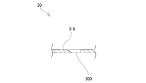
- ⁇ Third embodiment> 35 is a partial cross-sectional view showing a suturing tool 20c ′ according to a third embodiment of the second aspect of the present invention
- FIG. 36 is a partial perspective view showing the suturing tool 20c ′
- FIG. 37 shows the suturing tool 20c ′. It is sectional drawing shown.
- the suturing tool 20c ′ of the present embodiment is different from the first embodiment in that the locking portion 21c ′ has a hollow structure and the suture thread 22c ′ is fixed in the hollow portion 300 ′.
- Locking part 21c 'of this embodiment is formed in the hollow.
- a through-hole 310 ′ penetrating inward and outward is formed in the hollow.
- the suture thread 22c ′ inserted from the through hole 310 ′ is fixed to the hollow interior by caulking around the locking portion 21c ′.
- the suture thread 22c ′ exiting from the through hole 310 ′ is inserted into one of the thread passages 23a ′ to 23d ′.
- the locking portion 21c ′ positioned at the fourth level has been described as an example, but the locking portions 21 ′, 21a ′, and 21b ′ positioned at the first to third levels are also the same. It has the structure of
- the locking portion 21c 'of the present embodiment is made of a metal such as stainless steel and is formed in a hollow cylindrical shape.
- the diameter of the hollow portion 300 ′ of the locking portion 21 c ′ is set to be equal to or larger than the diameter of the suture thread 22 c ′.
- the through hole 310 ′ passes through the hollow portion 300 ′ from the yarn passage 23 d ′ side, and has an elliptical opening shape.
- the inner diameter of the through hole 310 ′ is set to be equal to or larger than the diameter of the suture thread 22 c ′.
- the opening shape of the through hole 310 ′ according to the present embodiment may be an elliptical shape, a linear shape (slit shape), an oval shape, a square shape, or a polygonal shape.
- FIG. 36 A method of fixing the suture thread 22c ′ and a method of attaching it to the puncture needle 30 ′ will be described with reference to FIGS.
- one end of the suture thread 22c ′ is inserted into the hollow portion 300 ′ from the outside of the locking portion 21c ′ through the through hole 310 ′.
- the periphery of the engaging portion 21c ′ through which the suture thread 22c ′ passes is caulked to form a crimped portion 320 ′.
- the locking portion 21c ′ is fitted, and the inner wall bites into the suture thread 22c ′.
- the suture thread 22c ′ is fixed in the hollow portion 300 ′, and the suture thread 22c ′ is prevented from dropping out of the through hole 310 ′.
- the locking portion 21c ′ is inserted into the storage portion 32 ′ of the puncture needle 30 ′.
- the crimping portion 320 ′ is inserted toward the needle tip side of the puncture needle 30 ′, and the suture thread 22c ′ exiting from the through hole 310 ′ extends along the thread passage 23d ′ as shown in FIG. It is led out of the puncture needle 30 '.
- the locking portion 21c ′ positioned at the fourth level in FIG. 22 will be described as an example, and the locking portions 21 ′, 21a ′, and 21b ′ positioned at the first to third levels are the same. is there.
- the through hole of the first locking portion 21 ′ is formed in the middle portion of the yarn passage 23a ′.
- the suture thread 22 ' is inserted into the puncture needle 30' along the thread passage 23a '.
- the through hole of the second-stage locking portion 21a ′ is formed in the middle portion of the yarn passage 23b ′.
- the suture thread 22a ′ is inserted into the puncture needle 30 ′ along the thread passage 23b ′.
- the through hole of the third locking portion 21b ′ is formed in the middle portion of the yarn passage 23c ′.
- the suture thread 22b ′ is inserted into the puncture needle 30 ′ along the thread passage 23c ′.
- the four types of locking portions 21 ′ and 21a ′ to 21c ′ can have the same shape.
- FIG. 38 is a partial cross-sectional view showing a suturing tool 20 ′ according to a fourth embodiment of the second aspect of the present invention
- FIG. 39 is a perspective view showing a locking portion.
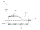
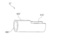
- the suturing tool 20 'of the present embodiment is different from the first to third embodiments in that the locking portion 21' has a hollow structure and the hollow portion 400 'is used as a "thread passage". To do.
- the suturing tool 20 ′ according to the present embodiment has a flat portion 420 ′ formed around the locking portion 21 ′ and the first to the second points in that the suture thread 22 ′ is joined to the flat portion 420 ′. This is different from the third embodiment.
- the locking portion 21 ′ of this embodiment is formed hollow.
- the present embodiment is characterized in that the inside of the hollow cylinder of the locking portion 21 ′, that is, the inside of the hollow portion 400 ′ is a yarn passage.
- a flat portion 420 ′ to which the suture thread 22 ′ can be joined is formed on the peripheral surface of the locking portion 21 ′. Not only the locking portion 21 'positioned at the first stage, but also the locking portions 21a' to 21c 'positioned at the other second to fourth stages have the same structure.
- the locking portion 21 ′ has a slit 410 ′ that extends from the end face on the base end side to the middle of the length, that is, extends from the end face on the base end side to the base end side from the end face on the tip end side. Is formed.
- the suture thread 22 ' is joined to one of the inner and outer peripheral surfaces on the distal end side of the locking portion 21', for example, the flat portion 420 'located outside.
- the joined suture thread 22 ′ is drawn into the hollow cylinder of the locking portion 21 ′, that is, the hollow portion 400 ′ via the slit 410 ′.
- the locking portion 21 ′ positioned at the first level has been described as an example, but the locking portions 21a ′ to 21c ′ positioned at the second to fourth levels have the same structure. I have.
- the locking portion 21 ′ of this embodiment is made of a metal such as stainless steel and is formed in a hollow cylindrical shape.
- the slit 410 ′ and the flat portion 420 ′ are positioned adjacent to each other and formed separately in one half of the locking portion 21 ′.
- the slit 410 ' is positioned on the proximal end side when the locking portion 21' is inserted into the puncture needle 30 ', and the flat portion 420' is positioned on the needle tip side of the puncture needle.
- the groove width of the slit 410 ' is set to be equal to or larger than the diameter of the suture thread 22'.
- the width of the flat portion 420 ' is set to be equal to or larger than the diameter of the suture thread 22'.
- FIG. 38 illustrates the case of heat sealing or adhesive fixing.
- the distal end portion of the suture thread 22 ′ is positioned toward the side opposite to the slit 410 ′, that is, toward the needle tip side when inserted into the puncture needle.
- the locking portion 21 ′ is inserted into the puncture needle 30 ′.
- the fixing portion 430 ′ is inserted toward the needle tip side of the puncture needle.
- the suture thread 22 ′ is led into the hollow portion 400 ′ through the slit 410 ′ and led out through the hollow portion 400 ′ that is a “thread passage”.
- FIG. 40 is a partial perspective view showing the suture instrument 20 ′ according to the fifth embodiment of the second aspect of the present invention.
- the suturing tool 20 ′ of the present embodiment is different from the first to fourth embodiments in that the locking portion 21 ′ has a hollow structure and the suture thread 22 ′ is joined to the inner peripheral surface of the hollow portion 500 ′. Is different.
- a suture thread 22 ' is joined to the inside of the tube on the distal end side of the locking portion 21' of the present embodiment.
- the locking portion 21 ′ positioned at the first stage has been described as an example, but the locking sections 21a ′ to 21c ′ positioned at the other second to fourth stages have the same structure. Is provided.
- the locking portion 21 ′ of the present embodiment is made of a metal such as stainless steel and is formed in a hollow cylindrical shape.
- the inside of the hollow cylinder of the locking portion 21 ′ that is, the inside of the hollow portion 500 ′ is used as a yarn passage.
- the locking portion 21 ′ is formed with a slit 510 ′ that extends from the end face on the base end side to the middle of the length.
- the slit 510 ′ is formed in one half of the locking portion 21 ′.
- the slit 510 ′ is positioned on the proximal end side when the locking portion 21 ′ is inserted into the puncture needle 30 ′ (see FIG. 22).
- the groove width of the slit 510 ′ is set to be equal to or larger than the diameter of the suture thread 22 ′.
- a method for fixing the suture thread 22 ′ to the locking portion 21 ′ and a method for attaching the suture thread 22 ′ to the puncture needle (not shown) will be described with reference to FIG.
- one end of the suture thread 22 ′ is inserted into the hollow portion 500 ′ through the slit 510 ′.
- the tip end of the one end of the suture thread 22 ′ is positioned on the inner wall surface of the hollow portion 500 ′, and is heat-sealed or bonded and fixed to form a fixing portion 520 ′.
- the distal end portion of the suture thread 22 ′ is positioned toward the side opposite to the slit 510 ′, that is, toward the needle tip side when inserted into the puncture needle.
- the locking portion 21 ' is inserted into the puncture needle 30'.
- the fixing portion 520 ' is inserted toward the needle tip side of the puncture needle 30'.
- the suture thread 22 ' is introduced into the hollow portion 500' through the slit 510 ', and is led out of the puncture needle 30' through the hollow portion 500 'that is a "thread passage". .
- FIG. 41 is a partial perspective view showing the locking portion of the sixth embodiment of the second aspect of the present invention.
- This embodiment is different from the first to fifth embodiments in that concave and convex portions 600 ′ and 610 ′ that are fitted to each other are formed on the end surfaces of the locking portions 21 ′ and 21 a ′ of the present embodiment.
- Concave and convex portions 600 ′ and 610 ′ that fit each other are formed on the end surfaces of at least a pair of the locking portions 21 ′ and 21 a ′ that face each other.
- the engaging portions 21 ′ and 21a ′ positioned in the first and second stages have been described as examples. However, although not illustrated, the engaging portions 21a ′ positioned in the second stage and the third stage are illustrated. An uneven portion having a similar structure is provided between the locking portion 21b 'positioned at the second position, or between the locking portion 21b' positioned at the third level and the locking portion 21c 'positioned at the fourth level.
- the uneven portions 600 'and 610' have a non-circular cross section.
- the recessed portion 600 ′ is formed on the end face on the base end side (upper side in FIG. 41) of the first-stage locking portion 21 ′ in FIG. 22.
- the concave portion 600 ′ of the present embodiment is a concave shape having a square cross section.
- the transverse section is a section obtained by cutting the locking portion 21 ′ in a direction perpendicular to the axial direction.
- the concave portion 600 ' has a bottom and extends in a concave shape in the axial direction from the center of the end surface of the locking portion 21'.
- the convex portion 610 ′ is formed to protrude in the shape of a prism at the center of the end surface on the distal end side (downward in FIG. 41) of the locking portion 21 a ′.
- the cross-sectional shape of the convex portion 610 ' corresponds to the concave portion 600'.
- the convex portion 610 ′ of the locking portion 21 a ′ is fitted with the concave portion 600 ′ on the end surface on the base end side (upper side in FIG. 41) of the other locking portion 21 ′ located on the distal end side.
- the relationship between the depth of the concave portion 600 ′ and the total length of the convex portion 610 ′ may be such that the depth of the concave portion 600 ′ is equal to or greater than the total length of the convex portion 610 ′.
- the two locking portions 21 ′ and 21a ′ are not shown in the drawing, when the concave and convex portions 600 ′ and 610 ′ are fitted to each other when inserted into the puncture needle, the adjacent locking portions 21 ′ and 21a ′.
- the relative rotation around the axis of the is regulated. Accordingly, for example, if the sixth embodiment is applied to the fifth embodiment, it is possible to prevent the sutures 22 ′ and 22 a ′ from being twisted and tangled with each other inside the hollow portion 500 ′.
- the engagement portion may be formed hollow to make the inside of the cylinder a yarn passage, and another yarn passage may be formed in a groove shape on the peripheral surface of the engagement portion.
- another yarn passage may be formed in a groove shape on the peripheral surface of the engagement portion.
- the locking portion is a columnar shape, but may be a hollow cylindrical shape instead.
- the cross-sectional shape of the locking portion is not limited to a circle, and may be a polygon.
- the suture tool in which one suture thread is fixed to the locking portion is illustrated, but the present invention is not limited to this.
- a plurality of sutures may be fixed to the locking portion.
- the state in which the suture is fixed to the center of the locking portion is illustrated, but the suture may be fixed to the end of the locking portion, or a single suture may be looped. You may fix the both ends to the both ends of a latching
- the cross-sectional shape of the yarn passages 23a ′ to 23d ′ is semicircular as shown in FIG. 21, but the present invention is not limited to this.
- the cross-sectional shape of the yarn passage may be, for example, U-shaped, ⁇ -shaped, rectangular or polygonal.
- the four yarn passages 23a ′ to 23d ′ are uniformly distributed around the locking portions 21 ′ and 21a ′ to 21c ′, but the four yarn passages 23a ′ to 23d are formed.
- the number of the suturing tools 20 ′, 20a ′ to 20c ′ is four, but may be two, three, or five or more.
- the fixing groove 200 ′ is formed at the center of the locking portion 21c ′, but may be formed closer to one end.
- the fixing groove 200 ′ it has been illustrated that one end of the suture thread 22c ′ is bound and fixed to the fixing groove 200 ′.
- heat fusion or adhesion may be performed.
- a plurality of suturing tools including a rod-shaped engaging portion and a suture thread having an end connected to the engaging portion, and a plurality of the engaging portions are arranged side by side in the proximal direction.
- a puncture needle wherein the plurality of locking portions are pushed out one by one from the puncture needle one by one by operation of the operation portion main body, and the suture instrument stored on the distal end side
- a repetitive organ fixing device characterized in that a thread passage for inserting a suture thread inside the puncture needle is formed in the locking portion of the other suture instrument housed on the proximal end side.
- the locking portion is formed hollow, a through-hole penetrating inward and outward is formed in the middle of the locking portion in the long axis direction, and the suture thread inserted from the through-hole is connected to the engagement portion.
Landscapes
- Health & Medical Sciences (AREA)
- Surgery (AREA)
- Life Sciences & Earth Sciences (AREA)
- Biomedical Technology (AREA)
- Nuclear Medicine, Radiotherapy & Molecular Imaging (AREA)
- Engineering & Computer Science (AREA)
- Heart & Thoracic Surgery (AREA)
- Medical Informatics (AREA)
- Molecular Biology (AREA)
- Animal Behavior & Ethology (AREA)
- General Health & Medical Sciences (AREA)
- Public Health (AREA)
- Veterinary Medicine (AREA)
- Rheumatology (AREA)
- Surgical Instruments (AREA)
Abstract
Description
本願は、2013年2月22日に、日本に出願された特願2013-033027号、及び2013年3月22日に、日本に出願された特願2013-059321号に基づき優先権を主張し、その内容をここに援用する。 The present invention relates to an organ fixing tool mainly used for percutaneous endoscopic gastrostomy (PEG).
This application claims priority based on Japanese Patent Application No. 2013-033027 filed in Japan on February 22, 2013 and Japanese Patent Application No. 2013-059321 filed on March 22, 2013 in Japan. , The contents of which are incorporated herein.
この方式だと、各固定箇所に2本の穿刺針を穿刺する必要があるため高侵襲であり、また医師の技量によっては胃の中で縫合糸をループ体で捕捉することが難しい場合があった。 In a general gastrostomy, it is necessary to fix the body wall and the gastric wall at at least three (4 in some cases) so as to surround the gastrostomy scheduled part. After the gastrostomy is constructed, the suture is cut and removed.
This method is highly invasive because two puncture needles need to be punctured at each fixed location, and depending on the skill of the doctor, it may be difficult to capture the suture with a loop body in the stomach. It was.
特許文献1の器具は、穿刺針の内部に複数個の縫合具が収容されて個別に押し出すことが可能な形態(以下、連発式という)である。具体的には、4個の縫合具が穿刺針に収容されている。このため、1回の手技において3~4箇所で胃壁を体壁に固定するにあたり、1個の器具でこれを実現することができる。このため、器具を廃棄、開封、持ち替えるなどの交換作業が不要になるため簡便である。
特許文献1の縫合具では、係止部に1本の縫合糸が係合している。かかる縫合具を体表に固定するにあたっては、その縫合糸を他の縫合具の縫合糸と体表で互いに結びつける。 On the other hand, according to the instrument (prior art) of
The instrument of
In the suture tool of
また、特許文献1の臓器固定具は、穿刺針が太く高侵襲であるという課題がある。すなわち、特許文献1の臓器固定具は、穿刺針の内部に4個の縫合具を収容すると、最上段、すなわち押出装置側の穿刺針の内部に通る係止部の周囲には4本の縫合糸が分散して配置されることとなる。このため、穿刺針の内径は少なくとも、係止部の外径に加えて、その両側に2本分の縫合糸の太さを合計しただけの寸法が必要である。このため、特許文献1の臓器固定具は、1個の縫合具のみを収納した単発式のものと比較し、穿刺針の外径が太くなる。
したがって、特許文献1の器具は、連発式であることによる手技上のメリットはあるものの、縫合糸が絡まって操作困難になるリスクと、穿刺針が太く高侵襲であるという課題がある。
また、特許文献2の臓器固定具は、単発式であるため、胃壁と体壁との1点の固定ごとに1個の器具が必要であり、器具の交換が煩雑であるとともにコストが高いという課題がある。 The organ fixing device of
Moreover, the organ fixing tool of
Therefore, although the instrument of
Moreover, since the organ fixing tool of patent document 2 is a single shot type, one instrument is required for each fixation of the stomach wall and the body wall, and the replacement of the instrument is complicated and the cost is high. There are challenges.
本発明の第二の態様によれば、棒状の係止部と、上記係止部に端部が連結された縫合糸の複数個と、からなる縫合具と、複数個の上記係止部を先基端方向に並べて収納する穿刺針と、を有し、操作部本体の操作によって上記複数個の係止部が上記穿刺針から一個ずつ押し出される連発式の臓器固定具であって、先端側に収納された上記縫合具の縫合糸を上記穿刺針の内部で挿通するための糸通路が、基端側に収納された他の上記縫合具の上記係止部に形成されていることを特徴とする連発式の臓器固定具が提供される。 According to the first aspect of the present invention, a plurality of suture tools comprising a rod-shaped locking portion and a suture thread coupled to the locking portion, and a puncture needle that houses a plurality of the locking portions And a plurality of the locking portions that are pushed out from the puncture needle one by one by operating the operation portion main body, wherein at least one of the plurality of locking portions A repetitive organ fixing device is provided in which a suture thread connected to a locking portion is inserted into the puncture needle, and another suture thread is led out from the inside of the puncture needle. The
According to the second aspect of the present invention, a suturing tool comprising a rod-shaped engaging portion and a plurality of sutures having ends connected to the engaging portion, and a plurality of the engaging portions. A puncture needle which is stored side by side in the proximal direction, and is a repetitive organ fixing device in which the plurality of locking portions are pushed out from the puncture needle one by one by operation of the operation portion main body, A thread passage for inserting the suture thread of the suture tool housed in the inside of the puncture needle is formed in the locking portion of the other suture tool housed on the proximal end side. A repetitive organ fixing device is provided.
上記第二の態様の発明によれば、係止部に形成された糸通路を通じて穿刺針の内部に縫合糸を挿通することができる。これにより、連発式のメリットを有しつつ、穿刺針を細径化することができるため低侵襲の臓器固定具が実現できる。 According to the first aspect of the invention, the number of sutures passing through the puncture needle can be reduced. Therefore, there are provided a repetitive organ fixing device that can improve the stability of the operation based on the reduction of the entanglement of the suture thread inside the puncture needle and can prevent the outer diameter of the puncture needle from expanding.
According to the second aspect of the invention, the suture can be inserted into the puncture needle through the thread passage formed in the locking portion. Thereby, since it is possible to reduce the diameter of the puncture needle while having the merit of repetitive type, a minimally invasive organ fixing device can be realized.
以下、本発明の第一の態様の実施形態を図面に基づいて説明する。図中、同様の構成要素には同様の符号を付し、重複する説明を省略する場合がある。 <First aspect>
Hereinafter, an embodiment of the first aspect of the present invention will be described with reference to the drawings. In the drawings, similar components are denoted by the same reference numerals, and redundant description may be omitted.
図1は、本発明の第一の態様の第一実施形態の臓器固定具を示す一部断面図、図2は臓器固定具を示す概略斜視図、図3は臓器固定具を示す一部側面図、図4は臓器固定具の内部機構を示す一部透視図、図5は操作部を示す側面図、図6は操作部を示す他の側面図、図7は第一実施形態の操作部の係合爪を押し込んだ状態を示す側面図、図8は臓器固定具を腹部に穿刺した状態を示す断面図、図9は臓器固定具の操作部が下降した状態を示す断面図、図10は係止部が胃壁の内部に係合した状態を示す断面図、図11は図1のA-A線に沿う断面図、図12は図1のB-B線に沿う断面図である。 <First embodiment>
1 is a partial sectional view showing an organ fixing device according to a first embodiment of the first aspect of the present invention, FIG. 2 is a schematic perspective view showing the organ fixing device, and FIG. 3 is a partial side view showing the organ fixing device. 4 is a partial perspective view showing the internal mechanism of the organ fixing device, FIG. 5 is a side view showing the operation unit, FIG. 6 is another side view showing the operation unit, and FIG. 7 is the operation unit of the first embodiment. FIG. 8 is a cross-sectional view showing a state in which the organ fixing tool is punctured in the abdomen, FIG. 9 is a cross-sectional view showing a state in which the operation part of the organ fixing tool is lowered, and FIG. FIG. 11 is a cross-sectional view showing a state in which the locking portion is engaged with the inside of the stomach wall, FIG. 11 is a cross-sectional view taken along line AA in FIG. 1, and FIG. 12 is a cross-sectional view taken along line BB in FIG.
縫合具20,20aは、図1に示すように、棒状の係止部21,21aと、係止部21,21aに連結された縫合糸22,22aと、からなる。
穿刺針30は、少なくとも係止部21,21aを複数個、本実施形態においてはたとえば2個収納できるものである。
押出装置40は、操作部本体63の操作によって複数個(たとえば2個)の係止部21,21aを穿刺針30から一個ずつ押し出すものである。
上記構造を前提とし、縫合具20,20aは、図1に示すように、複数個(たとえば2個)の係止部21,21aの一部の縫合糸22aが穿刺針30の内部に挿通され、他の縫合糸22が穿刺針30の軸線方向の側面において、穿刺針30の内部から外部に導き出されていることを特徴とする。なお、本明細書では、穿刺針30の針先31側を先端側といい、穿刺針30の押出装置40に固定された側を基端側という。 As shown in FIGS. 1 and 2, the
As shown in FIG. 1, the
The
The push-out
Assuming the above structure, the
縫合具20,20aは、図1に示すように、臓器固定具100に複数個、たとえば2個装填され、連発式で使用される。
縫合具20,20aは、穿刺針30の針先31側、すなわち穿刺針30の先端側から順に一段目の縫合具20と、次段に位置する二段目の縫合具20aと、からなる。以下、縫合具の段数とは、穿刺針30の先端側からみた順番をいう。
係止部21,21aは、ステンレス鋼に例示される金属製の棒状、たとえば円柱形である。ただし、係止部21,21aを樹脂等の非金属材料で作製してもよい。
縫合糸22,22aは、各1本で、その一端部を係止部21,21aの長さ(軸線方向)の途中、たとえば係止部21,21aの中央部分等に、熱融着または接着固定されているか、或いは、係止部21,21aの周囲をかしめることにより固定されている。縫合糸22,22aの他端部は穿刺針30の内部または外部を通じて臓器固定具100の外部に導き出されている。 Next, the
As shown in FIG. 1, a plurality of, for example, two
The
The locking
One
穿刺針30は、ステンレス製の円筒からなる注射針であって、図1に示すように、穿刺針30の内部は、係止部21,21aが挿通自在の収納部32となっている。
収納部32は、穿刺針30の軸芯方向に沿って、係止部21,21aを複数個、たとえば2個収納できるものである。
収納部32は、一端部が針先31に開放し、他端部が押出装置40に連通する。
収納部32は、中空で、その全長が係止部21,21aの2個分の長さ以上に設定されている。 Next, the
The
The
One end of the
The
本明細書において長径とは、穿刺針30又は係止部21,21aの断面形状である円形、楕円形、多角形等を包含し得る最小径の真円(外接円)の直径と定義され、短径とは、穿刺針30又は係止部21,21aの断面形状である円形、楕円形、多角形等に内包され得る最小径の真円(内接円)の直径と定義される。また、縫合糸の断面形状が真円形である場合の短径、長径とは、該真円の直径と読み替えられる。穿刺針30及び係止部21,21aの断面形状は真円に限定されるものではなく、楕円形であっても、多角形等であってもよい。
すなわち、次のような関係にある。
(1)第一の合計長=係止部の短径+縫合糸の短径×1(本)
(2)第二の合計長=係止部の長径+縫合糸の長径×2(本)
(3)第一の合計長=<穿刺針の内径<第二の合計長
また、上記関係に加えて、以下の関係を満たすことが好ましい。
(4)第三の合計長=係止部の短径+縫合糸の短径×2(本)
(5)第一の合計長=<穿刺針の内径<第三の合計長
したがって、本実施形態の臓器固定具100によれば、特許文献1の器具のように係止部の周囲の両側に対向して複数本の縫合糸を通す場合と比較して、穿刺針30の外径を細くすることができる。なお、図12では便宜上、係止部21,21aおよび縫合糸22,22aが穿刺針30に遊挿されている状態を図示してあるが、上記のように穿刺針30の内径は、第一の合計長以上且つ第二の合計径未満であることが好ましく、第一の合計長以上且つ第三の合計長未満であることがより好ましい。 The inner diameter of the
In this specification, the major axis is defined as the diameter of a perfect circle (a circumscribed circle) having a minimum diameter that can include a circular shape, an elliptical shape, a polygonal shape, and the like, which are cross-sectional shapes of the
That is, it has the following relationship.
(1) first total length = short diameter of the locking portion + short diameter of the suture × 1 (piece)
(2) Second total length = long diameter of locking portion + long diameter of suture × 2 (book)
(3) First total length = <Inner diameter of puncture needle <Second total length In addition to the above relationship, it is preferable that the following relationship is satisfied.
(4) Third total length = minor axis of locking portion + minor axis of suture × 2 (book)
(5) First total length = <Inner diameter of puncture needle <Third total length Therefore, according to the
これにより、2本の縫合糸22,22aは穿刺針30の内外に別れて経路が全く異なり、また交差することもないため、2本の縫合糸22,22aの絡まりを完全に防止できる。 In this embodiment, since there are two
As a result, the two
押出装置40は、連発式の動作を行うためのものである。
押出装置40は、図2から7に示すように、大別すると、筒部50と、操作部60と、把持部70と、ロック装置80と、からなる。 Next, the
The
As shown in FIGS. 2 to 7, the
また、筒部50には、図4に示すように、内外に貫通する糸出用孔51を設けている。糸出用孔51は、穿刺針30の収納部32内を通って筒部50の内部に導き出された縫合糸22aが通る。 The
Further, as shown in FIG. 4, the
操作部60は、図2から7に示すように、大別すると、押出棒61と、押圧部62と、操作部本体63と、からなる。 The
As shown in FIGS. 2 to 7, the
把持部70は、合成樹脂製の平板形であって、押出装置40を把持するものである。
把持部70は、図2に示すように、同図において筒部50の下側から左右両側に向かって対称に板状に張り出している。 Next, the gripping
The gripping
As shown in FIG. 2, the gripping
ロック装置80は、筒部50に対して操作部60が不用意にスライドすることを規制する。
ロック装置80は、図4に示すように、大別すると、係合爪81と、凹部82,82aと、からなる。これに加え、筒部50には、ロック装置80のロック状態を解除する解除用ボタン83,84が設けられている。 Next, the locking
The locking
As shown in FIG. 4, the locking
凹部82,82aは、筒部50の内外に貫通し、筒部50の内周側から係合爪81が嵌り込み、外周側には後述する解除用ボタン83,84がそれぞれ取り付けられている。
図4において上側に位置する凹部82に係合爪81が嵌り込んだ状態では、押出棒61の先端部が、図8に示すように、穿刺針30の収納部32内に収納された二段目、すなわち同図に上側に位置する係止部21aに臨む。
上側に位置する凹部82に係合爪81が嵌り込んだ状態では、それ以上、操作部60が筒部50の内部に押し込まれることが阻止され、縫合具20,20aが穿刺針30の針先31から押し出されることが防止される。また、操作部60が筒部50の内部から抜けることも規制される。
上側に位置する凹部82に嵌り込んでいた係合爪81が、図4において下側に位置する凹部82aに向かって進むと、二段目の係止部21aは、押出棒61に押されて針先31側に進む。このため、一段目の係止部21は、二段目の係止部21aに押されて針先31から押し出される。
当該位置で、下側に位置する凹部82aに、係合爪81が嵌り込む。下側に位置する凹部82aに係合爪81が嵌り込んだ状態では、それ以上、操作部60が筒部50の内部に押し込まれることが阻止され、二段目の縫合具20aが穿刺針30の針先31から押し出されることが防止される。 As shown in FIG. 4, the
The
In the state where the engaging
In a state where the engaging
When the engaging
At this position, the engaging
解除用ボタン83,84は、図4に示すように、上下の凹部82,82aに筒部50の外周側から嵌り込み、図示しないが、板バネやコイルバネのバネ力で外周から突出する。 The
As shown in FIG. 4, the
臓器固定具100は、係合爪81が、図4において上側に位置する凹部82に嵌り込んだ状態を初期状態として使用される。 Next, with reference to FIGS. 8 to 10, a method of using the
The
つぎに、図9に示すように、同図において上側に位置する解除用ボタン83を押圧する。解除用ボタン83を押圧すると、同図にて上側に位置する凹部82に嵌り込んでいた係合爪81が係脱し、ロック装置80のロック状態が解除される。
その後、操作部本体63を、図9に示すように、筒部50の内部に向かって押圧する。
操作部本体63を押圧すると、押出棒61が穿刺針30の収納部32内を進行し、二段目の係止部21aを介して、一段目の係止部21が針先31から押し出される。
このため、一段目の係止部21が、図9に示すように、胃腔内に投入される。
臓器固定具100は、穿刺針30を体外に引き抜いて回収する。
つぎに、一段目の係止部21の縫合糸22を、図10に示すように、体外から引っ張ることで、係止部21が胃壁Bを皮膚側壁A側に引き寄せられる。その後、縫合糸22を体外側に固定することで、胃壁Bが皮膚側壁Aに固定される。 As shown in FIG. 8, the
Next, as shown in FIG. 9, the
Then, the operation part
When the operation portion
For this reason, the first
The
Next, as shown in FIG. 10, the locking
つぎに、図4において下側に位置する解除用ボタン84を押圧する。解除用ボタン84を押圧すると、同図において、下側に位置する凹部82aに嵌り込んでいた係合爪81が係脱し、ロック装置80のロック状態が解除される。
その後、操作部本体63を、筒部50の内部に向かって押圧する。
操作部本体63を押圧すると、押出棒61が穿刺針30の収納部32内を進行し、二段目の係止部21aが針先31から押し出される。
このため、二段目の係止部21aが、胃腔内に投入される。
二段目の係止部21aの縫合糸22aを、一段目の縫合糸22と同様に、体外から引っ張って固定することで、胃壁Bが皮膚側壁Aに固定される。 Thereafter, although not shown, the collected
Next, the
Thereafter, the operation portion
When the operation portion
For this reason, the
The stomach wall B is fixed to the skin side wall A by pulling and fixing the
図13は、本発明の第一の態様の第二実施形態の臓器固定具を示す一部断面図、図14は図13のC-C線に沿う断面図、図15は図13のD-D線に沿う断面図である。
本実施形態の臓器固定具100は、第一に、縫合具20,20a~20cの本数を増加した点で第一実施形態と相違する。
第二に、本実施形態の臓器固定具100は、スリット200を延長した点で第一実施形態と相違する。 <Second embodiment>
13 is a partial cross-sectional view showing an organ fixing device according to a second embodiment of the first aspect of the present invention, FIG. 14 is a cross-sectional view taken along the line CC of FIG. 13, and FIG. It is sectional drawing which follows a D line.
The
Secondly, the
すなわち、本実施形態の4本の縫合糸22,22a~22cは、そのうち、2本の一段目、二段目の縫合糸22,22aが穿刺針30の外部、残る2本、すなわち三段目、四段目の縫合糸22b,22cが穿刺針30の内部(収納部32)を通っている。隣接する縫合糸22,22a~22cは、穿刺針30の外周方向に離間し、かつ等間隔、すなわち90度間隔で配置されている。 Of the four or more (four in this embodiment) sutures 22, 22a to 22c, the
That is, of the four
図16は、本発明の第一の態様の第三実施形態の臓器固定具を示す一部断面図、図17は穿刺針を示す一部拡大断面図、図18は穿刺針を示す断面図である。
本実施形態の臓器固定具100は、第一に、第二実施形態と同様に、縫合具20,20a~20cの本数を増加した点で第一実施形態と相違する。
第二に、本実施形態の臓器固定具100は、貫通部として横孔300を設けた点で第一および第二実施形態と相違する。 <Third embodiment>
16 is a partial cross-sectional view showing an organ fixing device according to a third embodiment of the first aspect of the present invention, FIG. 17 is a partial enlarged cross-sectional view showing a puncture needle, and FIG. 18 is a cross-sectional view showing the puncture needle. is there.
The
2ndly, the
収納部32内に収納された係止部21,21a~21cの縫合糸22,22a~22cのいずれかが横孔300を通って穿刺針30の外部に導き出されることにより、横孔300は貫通部として機能する。
図16では、横孔300は側面視円状に1個形成され、その内径を縫合糸22bの太さ以上に設定している。横孔300は、収納部32内に収納された三段目の縫合具20bの縫合糸22bの配置領域に位置し、当該縫合糸22bがその孔内を通って穿刺針30の外部に導き出される。 The
Any one of the
In FIG. 16, one
一段目の係止部21の縫合糸22は、図16に示すように、スリット33を通って穿刺針30の内部から外部に導き出されている。三段目の係止部21bの縫合糸22bは、横孔300を通って穿刺針30の内部から外部に導き出されるが、このとき、スリット33と横孔300とが穿刺針30の周方向において180度位相が異なっていることから、一段目の縫合糸22と三段目の縫合糸22bとが穿刺針30を挟んで対向位置する。 As shown in FIG. 18, the
As shown in FIG. 16, the
図19は、本発明の第一の態様の第四実施形態の臓器固定具を示す一部側面図である。
本実施形態の臓器固定具100は、スリット400が穿刺針30の表面に、軸線に対して非直線的に形成されている点で第一および第二実施形態と相違する。 <Fourth embodiment>
FIG. 19 is a partial side view showing the organ fixing device according to the fourth embodiment of the first aspect of the present invention.
The
スリット400は、図示しないが、一端部が針先に開放され、図19に示すように、他端部が穿刺針30の軸線方向、すなわち同図において上方に向かって途中まで直線的に延びた後、スリット400の当該他端部が円弧状に屈曲し、更にその端部が上方に向かって直線的に延びて行き止まりに形成されている。すなわち、スリット400は、軸線方向に直線であって互いに離間した2本の直線スリットと、該2本の直線スリットを連通するスリットとを有し、これらのスリットが一体となって形成されたものである。
行き止まりの他端部の位置は、第二実施形態のスリット200と同様である。図13を用いて説明すると、収納部32内に収納された状態の二段目の縫合具20aの縫合糸22aの配置領域まで延在していることが必要であるが、これより長く、押出装置40側に亘って延在していてもよい。
スリット400は、穿刺針30の周方向に螺旋状に形成されていてもよい。長さの途中が螺旋状に形成されることにより、第二実施形態のスリット200と同様に、一段目の縫合糸22と二段目の縫合糸22aとを90度位相を異ならせて、図13のように穿刺針30の外部に導き出すことができる。 The
Although not shown, the
The position of the other end of the dead end is the same as that of the
The
図20は、本発明の第一の態様の第四実施形態の臓器固定具100を示す概略斜視図である。
本実施形態の臓器固定具100は、凹部500~503の個数を増加し、かつ筒部50の円周方向に位置を異ならせて配置している点で第一実施形態と相違する。 <Fifth embodiment>
FIG. 20 is a schematic perspective view showing the
The
凹部500~503は、図1を用いて既に説明した第一実施形態のものと同様に、縫合具20,20aが2本装填されているものを前提とし、計4個形成されている。
4個の凹部500~503のうち、2個の第1、第2の凹部500,501は、図20において上下に離れて配置されている。第1、第2の凹部500,501の間隔は、図1を用いて説明すると、針先31側に位置する一段目の係止部21を押し出すのに必要なストロークに一致させている。
4個の凹部500~503のうち、残る2個の第3、第4の凹部502,503は、筒部50の外周方向にずれ、且つ図20において上下に離れて配置されている。第3、第4の凹部502,503のうち、図20において上側に位置する第3の凹部502は、下側に位置する第2の凹部501と同じ高さに位置する。下側に位置する第4の凹部503は、第3の凹部502から下方に離れて位置する。第3、第4の凹部502,503の間隔は、図1を用いて説明すると、二段目の係止部21aを押し出すに必要なストロークに一致させている。 The recesses 500 to 503 penetrate through the inside and outside of the
As in the first embodiment already described with reference to FIG. 1, a total of four recesses 500 to 503 are formed on the premise that two
Of the four recesses 500 to 503, the two first and
Of the four recesses 500 to 503, the remaining two third and
まず、操作部60の係合爪81が、第1の凹部500に嵌り込んだ状態から、係合爪81を押し込みながら、操作部60を押し下げると、図20の下側に位置する第2の凹部501に嵌り込む。このとき、図1を用いて説明すると、一段目の係止部21が針先31から押し出される。
なお、操作部60を、更に押し下げようとしても、係合爪81が第2の凹部501に嵌り込んでいることから、操作部60の押し下げが防止される。 Next, with reference to FIG. 20, a method of using the
First, when the
Even if the
第2の凹部501に嵌り込んだ係合爪81を押し込みながら、操作部60を筒部50に対して回転させる。
操作部60を回転すると、係合爪81が第2の凹部501から第3の凹部502に移動し、第3の凹部502に嵌り込む。
その後、第3の凹部502に嵌り込んだ係合爪81を押し込みながら、操作部60を押し下げると、図20の下側に位置する第4の凹部503に嵌り込む。このとき、図1を用いて説明すると、二段目の係止部21aが針先31から押し出される。 Next, with reference to FIG. 1, when the first-
The
When the
Thereafter, when the operating
たとえば、上記第一実施形態において、係止部21,21aを円柱形としたが、中空の円筒形としてもよいし、または断面形状も円形に限らず、多角形としてもよい。
また、上記第一実施形態において、係止部21,21aに各1本の縫合糸22,22aを使用したが、複数本、2本の縫合糸を使用してもよい。第一実施形態では縫合糸22,22aを、係止部21,21aの中央に固定しているが、係止部21,21aの一端部でもよく、または1本の縫合糸をループさせてその両端部を係止部21,21aの両端部にそれぞれ固定してもよい。
たとえば上記第一実施形態において、一段目の縫合糸22が穿刺針30の外部、二段目の縫合糸22aが内部を取っているが、一段目の縫合糸22が穿刺針30の内部、二段目の縫合糸22aが外部を通っていてもよい。
たとえば上記第一実施形態において、操作部本体63を円板形に形成したが、棒状に形成してもよい。
たとえば上記第一実施形態において、把持部70を平板状に形成したが、リング状やレバー状に形成してもよい。また、把持部70は、筒部50と一体的に形成してもよいし、別体構造としてもよい。 The present invention is not limited to the above-described embodiment, and includes various modifications and improvements as long as the object of the present invention is achieved.
For example, in the first embodiment, the locking
In the first embodiment, one
For example, in the first embodiment, the first-
For example, in the first embodiment, the operation portion
For example, in the first embodiment, the
たとえば上記第二実施形態において、4本の縫合糸22,22a~22cのうち、2本の一段目、二段目の縫合糸22,22aが穿刺針30の外部を通り、残る2本、すなわち三段目、四段目の縫合糸22b,22cが内部を通っている。これに代えて、一段目、三段目の縫合糸22,22bが外部を通り、二段目、四段目の縫合糸22a,22cが内部を通るようにしてもよい。また、一段目、四段目の縫合糸22,22cが穿刺針30の外部を通り、二段目および三段目の縫合糸22a,22bが内部を通るようにしてもよい。また、第二実施形態では隣接する縫合糸22,22a~22cを90度間隔で配置したが、これに限定されず、隣接する縫合糸22,22a~22c同士を、穿刺針30を挟んで180度対向位置させてもよい。
たとえば、上記第二実施形態において、4個の縫合具20,20a~20cに代えて3個の縫合具20,20a~20bのみを用いる場合であれば、3本の縫合糸22,22a~22bのうち、2本の縫合糸が穿刺針30の外部を通り、残る1本が穿刺針30の内部を通っていてもよく;2本の縫合糸が穿刺針30の内部を通り、残る1本が穿刺針30の外部を通っていてもよいが、2本の縫合糸が穿刺針30の外部を通り、残る1本が穿刺針30の内部を通っていることが好ましい。 For example, in the first embodiment, the number of the
For example, in the second embodiment, of the four
For example, in the second embodiment, if only three
上記第三実施形態において、横孔300とスリット33とを180度位相を異ならせて配置したが、縫合糸22,22a~22cが絡まり難くするという意味では、180度に限定されない。
また、上記第一~第五実施形態において、後述する第二の態様の第六実施形態のように、隣接する2個の係止部の端面に互いに嵌合する凹凸部を形成し、隣接する係止部の軸心回りの相対的な回転を規制してもよい。 In the third embodiment, the
In the third embodiment, the
Further, in the first to fifth embodiments, as in the sixth embodiment of the second aspect described later, the concave and convex portions that are fitted to each other are formed on the end surfaces of the two adjacent locking portions, and adjacent to each other. The relative rotation around the axis of the locking portion may be restricted.
(1)棒状の係止部と、前記係止部に連結された縫合糸と、からなる縫合具の複数個と、前記係止部を複数個収納する穿刺針と、を有し、操作部本体の操作によって前記複数個の係止部が前記穿刺針から一個ずつ押し出される連発式の臓器固定具であって、前記複数個の係止部のうち少なくとも一個の係止部に連結された縫合糸が前記穿刺針の内部に挿通され、他の縫合糸が前記穿刺針の内部から外部に導き出されていることを特徴とする連発式の臓器固定具。
(2)前記穿刺針には、前記他の縫合糸が通る内外に貫通した貫通部が設けられている上記(1)に記載の連発式の臓器固定具。
(3)前記貫通部は、前記穿刺針の先端である針先から前記操作部本体に向かって延びるスリットを有する上記(2)に記載の連発式の臓器固定具。
(4)前記縫合具が2個であり、前記縫合糸の1本が前記穿刺針の外部、他の1本が内部を通っている上記(1)から(3)のいずれか一項に記載の連発式の臓器固定具。
(5)前記穿刺針の内径が、前記係止部の短径に前記縫合糸の短径を加えた第一の合計長以上であり、且つ前記係止部の長径に前記縫合糸の2本分の長径を加えた第二の合計長未満である上記(4)に記載の連発式の臓器固定具。
(6)前記縫合具は、3個以上であり、前記スリットは、穿刺針の先端側に位置する係止部の配置領域から、穿刺針の基端側の次段に位置する係止部の配置領域の少なくとも途中まで延びており、当該次段に位置する係止部の縫合糸が前記スリットに挿通されている上記(3)に記載の連発式の臓器固定具。
(7)前記スリットが螺旋状に形成されている上記(6)に記載の連発式の臓器固定具。
(8)前記縫合具は、3個以上であり、3本以上の縫合糸のうち、2個の縫合具の縫合糸が、前記穿刺針の内部から外部に導き出され、前記穿刺針に対して対向配置されている上記(1)から(3)、(6)または(7)のいずれか一項に記載の連発式の臓器固定具。
(9)前記貫通部として、前記穿刺針の内外に貫通する横孔を有する上記(2)、(3)、(6)、(7)または上記(2)に従属する上記(8)のいずれか一項に記載の連発式の臓器固定具。
(10)前記横孔の先端側の端面が、内側から外側に向かうに従って、先端方向から基端方向に向かうように傾斜している上記(9)に記載の連発式の臓器固定具。 The above embodiment includes the following technical idea.
(1) It has a rod-shaped locking part, a suture thread connected to the locking part, a plurality of suture tools, and a puncture needle that houses a plurality of the locking parts. A repetitive organ fixing device in which the plurality of locking portions are pushed out one by one from the puncture needle by operation of a main body, and sutures connected to at least one locking portion among the plurality of locking portions A repetitive organ fixing device, characterized in that a thread is inserted into the puncture needle and another suture thread is led out from the inside of the puncture needle.
(2) The repetitive organ fixing device according to (1), wherein the puncture needle is provided with a penetrating portion penetrating inward and outward through which the other suture thread passes.
(3) The continuous organ fixing device according to (2), wherein the penetrating portion includes a slit extending from a needle tip that is a tip of the puncture needle toward the operation portion main body.
(4) The device according to any one of (1) to (3), wherein the number of the suture tools is two, one of the sutures passes through the outside of the puncture needle, and the other one passes through the inside. The continuous organ fixator.
(5) An inner diameter of the puncture needle is not less than a first total length obtained by adding a minor axis of the suture to a minor axis of the locking part, and two of the sutures have a major axis of the locking part. The repetitive organ fixing device according to (4), which is less than the second total length including the major axis of the minute.
(6) The number of the suturing tools is three or more, and the slits are arranged on the locking portion located at the next stage on the proximal end side of the puncture needle from the arrangement region of the locking portion located on the distal end side of the puncture needle. The repetitive organ fixing device according to the above (3), which extends at least partway in the arrangement region and is inserted through the slit with a suture thread of a locking portion located in the next stage.
(7) The continuous organ fixing device according to (6), wherein the slit is formed in a spiral shape.
(8) The number of the suturing tools is three or more, and among the three or more suturing sutures, the sutures of two suturing tools are led out from the inside of the puncture needle to the puncture needle. The repetitive organ fixing device according to any one of (1) to (3), (6), and (7), which are arranged to face each other.
(9) Any of the above (2), (3), (6), (7) or (8) subordinate to (2) above, which has a lateral hole penetrating into and out of the puncture needle as the penetrating portion The continuous organ fixing device according to
(10) The repetitive organ fixing device according to (9), wherein an end surface on the distal end side of the horizontal hole is inclined from the distal end direction toward the proximal end direction from the inner side toward the outer side.
以下、本発明の第二の態様の実施形態を図面に基づいて説明する。図中、同様の構成要素には同様の符号を付し、重複する説明を省略する場合がある。 <Second aspect>
The second embodiment of the present invention will be described below with reference to the drawings. In the drawings, similar components are denoted by the same reference numerals, and redundant description may be omitted.
図21は、本発明の第二の態様の第一実施形態の臓器固定具を示す。図21は図22のA’-A’線に沿う断面図である。図22は臓器固定具を示す一部断面図である。図23は臓器固定具を示す概略斜視図、図24は臓器固定具を示す一部側面図、図25は臓器固定具の内部機構を示す一部透視図、図26は操作部を示す側面図、図27は操作部を示す他の側面図、図28は操作部の係合爪を押し込んだ状態を示す側面図である。図29は臓器固定具を腹部に穿刺した状態を示す断面図、図30は臓器固定具の操作部が下降した状態を示す断面図、図31は係止部が胃壁の内部に係合した状態を示す断面図である。 <First embodiment>
FIG. 21 shows the organ fixing device according to the first embodiment of the second aspect of the present invention. FIG. 21 is a sectional view taken along the line A′-A ′ of FIG. FIG. 22 is a partial cross-sectional view showing an organ fixing device. 23 is a schematic perspective view showing the organ fixing tool, FIG. 24 is a partial side view showing the organ fixing tool, FIG. 25 is a partial perspective view showing the internal mechanism of the organ fixing tool, and FIG. 26 is a side view showing the operation unit. 27 is another side view showing the operation unit, and FIG. 28 is a side view showing a state in which the engaging claw of the operation unit is pushed in. 29 is a cross-sectional view showing a state where the organ fixing tool is punctured in the abdomen, FIG. 30 is a cross-sectional view showing a state where the operation part of the organ fixing tool is lowered, and FIG. 31 is a state where the locking part is engaged with the inside of the stomach wall. FIG.
縫合具20’,20a’~20c’は、図21および図22に示すように、棒状の係止部21’,21a’~21c’と、係止部21’,21a’~21c’に端部が連結された縫合糸22’,22a’~22c’と、からなる。
穿刺針30’は、複数個、本実施形態においてはたとえば4個の係止部21’,21a’~21c’を先基端方向に並べて収納するものである。
本実施形態の連発式の臓器固定具100’が備える押出装置40’は、操作部本体63’の操作によって複数個(たとえば2個)の係止部21’,21a’を穿刺針30’から一個ずつ押し出すものである。
図22に示すように、先端側に収納された縫合具20’,20a’,20b’の縫合糸22’,22a’,22b’を穿刺針30’の内部で挿通するための糸通路23a’~23d’が、基端側に収納された他の縫合具20a’~20c’の係止部21a’~21c’に形成されている。
なお、本明細書では、穿刺針30’の針先31’側を先端側といい、穿刺針30’の押出装置40’に固定された側を基端側という。また、基端側から先端側へと向かう方向を、押出し方向ということがある。 As shown in FIGS. 21 to 23, the
As shown in FIGS. 21 and 22, the
A plurality of puncture needles 30 ′, for example, four locking
The
As shown in FIG. 22, a
In the present specification, the
縫合具20’,20a’~20c’は、図22に示すように、臓器固定具100’に複数本、たとえば4個装填され、連発式で使用される。
縫合具20’,20a’~20c’は、穿刺針30’の針先31’側、すなわち穿刺針30’の先端側から順に一段目の縫合具20’と、二段目の縫合具20a’と、三段目の縫合具20b’と、四段目の縫合具20c’と、からなる。 Next, the
As shown in FIG. 22, a plurality of, for example, four
The
係止部21’,21a’~21c’、すなわち四段目の縫合具20c’の係止部21c’の周囲には、図21に示すように、糸通路23a’~23d’が形成されている。 Next, the locking
As shown in FIG. 21,
すなわち、糸通路23a’~23d’は、係止部21c’の周面から、係止部21c’の軸心に向かって凹んだ、断面が半円形の溝状に削成されている。 Next, as shown in FIG. 21, the
That is, the
同様に、収納部32’の内径と、対向する糸通路23b’および23d’の最深部同士を通る係止部21c’の直径と、の差分は、縫合糸22a’および22c’の直径の合計よりも僅かに大きい。また、収納部32’の内径と、係止部21c’のうち糸通路23a’~23d’を除く部位の直径と、の差分は、縫合糸22a’および22c’の直径の合計よりも小さい。
係止部21’、21a’、21b’に関しても同様である。
これにより、本変形例の臓器固定具100’に関しても、係止部21’,21a’~21c’を順に押し出す際に、縫合糸22’,22a’~22c’は糸通路23a’~23d’にそれぞれ係合した状態から脱落することがなく、互いに絡まることがない。 The difference between the inner diameter of the
Similarly, the difference between the inner diameter of the
The same applies to the locking
Thereby, also in the
穿刺針30’の針先31’側から順に一段目の係止部21’は、図示しないが、自身の縫合糸22’が通る1個の糸通路があれば足りるが、糸通路を2個以上設けてもよい。
二段目の係止部21a’は、図示しないが、自身の縫合糸22a’が通る1個の糸通路に加え、一段目の縫合糸22’が通る計2個の糸通路があれば足りるが、糸通路を3個以上設けてもよい。
三段目の係止部21b’は、図示しないが、自身の縫合糸22bが通る1個の糸通路に加え、一段目、二段目の縫合糸22’,22a’が通る計3個の糸通路があれば足りるが、糸通路を4個以上設けてもよい。
四段目の係止部21c’は、図21に示すように、自身の縫合糸22c’が通る1個の糸通路23c’に加え、一段目~三段目の縫合糸22’,22a’,22b’が通る計4個の糸通路23a’~23d’があれば足りるが、糸通路を5個以上設けてもよい。 Here, the locking
Although not shown in the drawing, the
Although not shown in the drawing, the second-
Although not shown in the drawing, the third-
As shown in FIG. 21, the fourth-
なお、図22において四段目に位置する係止部21c’を例にあげて説明したが、他の一段目から三段目にそれぞれ位置する係止部21’,21a’、21b’にも同様の構造を備える。 Next, three or more, for example, four
In FIG. 22, the locking
収納部32’は、一端部が針先31’にて開放され、他端部が押出装置40’に連通されている。収納部32の直径、すなわち穿刺針30’の内径は、図1に示すように、係止部21’,21a’~21c’の直径よりも僅かに大きい。 The puncture needle 30 'is an injection needle made of a metal cylinder such as stainless steel. As shown in FIG. 22, engaging
One end of the
押出装置40’は、連発式の動作を行うためのものである。ここでは便宜上、2個の縫合具20’,20a’を装填して順に送り出すものを例にあげて説明する。
押出装置40’は、図23から図28に示すように、大別すると、筒部50’と、操作部60’と、把持部70’と、ロック装置80’と、からなる。 Next, the
The
As shown in FIGS. 23 to 28, the
係合爪81’は、図25から図27に示すように、押圧部62’に設けられ、その外周から凸形に突出する。押圧部62’が、円筒形に形成されていることから、その外周壁を切り欠くことで、凸形の部分が筒内部に弾性的にたわみ込むことができるようにしている。 The engaging
As shown in FIGS. 25 to 27, the engaging
凹部82’,82a’は、筒部50’の内外に貫通し、筒部50’の内周側からは係合爪81’が嵌り込み、外周側には後述する解除用ボタン83’,84’がそれぞれ取り付けられている。
図24において上側に位置する凹部82’に、係合爪81’が嵌り込んだ状態では、押出棒61’の先端部が、図28に示すように、穿刺針30’の収納部32’内に収納された二段目、すなわち同図に上側に位置する係止部21a’に臨む。
上側に位置する凹部82’に、係合爪81’が嵌り込んだ状態では、それ以上、操作部60’が筒部50’の内部に押し込まれるのを阻止し、縫合具20’,20a’が穿刺針30’の針先31’から押し出されるのを防止する。また、操作部60’が、筒部50’の内部から抜けるのを防止する。
上側に位置する凹部82’に嵌り込んでいた係合爪81’が、図24において下側に位置する凹部82a’に向かって進むと、押出棒61’に押されて、二段目の係止部21a’が針先31’側に進む。このため、二段目の係止部21a’に押されて、一段目の係止部21’が針先31’から押し出される。
当該位置で、下側に位置する凹部82a’に、係合爪81’が嵌り込む。下側に位置する凹部82a’に、係合爪81’が嵌り込んだ状態では、それ以上、操作部60が筒部50’の内部に押し込まれるのを阻止し、二段目の縫合具20a’が穿刺針30’の針先31’から押し出されるのを防止する。 As shown in FIG. 25, the
The
In the state where the engaging
In a state where the engaging
When the engaging
At this position, the engaging
その結果、係合爪81’が、凹部82’,82a’から係脱し、ロック状態が解除される。
解除用ボタン83’,84’は、図25に示すように、上下の凹部82’,82a’に筒部50’の外周側から嵌り込み、図示しないが、板バネやコイルバネのバネ力で外周から突出する。 The
As a result, the engaging
As shown in FIG. 25, the
まず、係合爪81’が、図25において上側に位置する凹部82’に嵌り込んだ状態で臓器固定具100’を使用する。
穿刺針30’を、図29に示すように、患者の体外から体壁(腹壁)A’および胃壁B’を貫通するまで穿刺し、胃内に針先31’を露出させる。
次に、図30に示すように、同図において上側に位置する解除用ボタン83’を押圧する。解除用ボタン83’を押圧すると、同図において、上側に位置する凹部82’に嵌り込んでいた係合爪81’が係脱し、ロック装置80’のロック状態が解除される。
その後、操作部本体63’を、図30に示すように、筒部50’の内部に向かって押圧する。
操作部本体63’を押圧すると、押出棒61’が穿刺針30’の収納部32’内を進行し、二段目の係止部21a’を介して、一段目の係止部21’が針先31’から押し出される。
このため、一段目の係止部21’が、図30に示すように、胃内に投入される。
臓器固定具100’は、穿刺針30’を体外に引き抜いて回収する。
つぎに、一段目の係止部21’の縫合糸22’を、図31に示すように、体外から引っ張り、係止部21’が胃壁B’を体壁A’側に引き寄せ、縫合糸22’を体外側に固定することで、胃壁B’が体壁A’に固定される。 A method of using the
First, the
As shown in FIG. 29, the
Next, as shown in FIG. 30, a release button 83 'located on the upper side in the drawing is pressed. When the
Thereafter, the operation portion
When the operation portion
For this reason, as shown in FIG. 30, the first-
The
Next, as shown in FIG. 31, the
次に、図25において下側に位置する解除用ボタン84’を押圧する。解除用ボタン84’を押圧すると、同図において、下側に位置する凹部82a’に嵌り込んでいた係合爪81’が係脱し、ロック装置80’のロック状態が解除される。
その後、操作部本体63’を、筒部50’の内部に向かって押圧する。
操作部本体63’を押圧すると、押出棒61’が穿刺針30’の収納部32’内を進行し、二段目の係止部21a’が針先31’から押し出される。このため、二段目の係止部21a’が、胃内に投入される。
二段目の係止部21a’の縫合糸22a’を、一段目の縫合糸22’と同様に、体外から引っ張って固定することで、胃壁B’が体壁A’に固定される。 Thereafter, although not shown, the collected
Next, the
Thereafter, the operation portion
When the operation portion
The stomach wall B ′ is fixed to the body wall A ′ by pulling and fixing the
図33は、本発明の第二の態様の第二実施形態の係止部を示す平面図、図34は縫合具を示す断面図である。
本実施形態の縫合具20c’は、その係止部21c’に固定溝200’が形成されている点で第一実施形態と相違する。 <Second embodiment>
FIG. 33 is a plan view showing a locking portion according to the second embodiment of the second aspect of the present invention, and FIG. 34 is a cross-sectional view showing the suturing tool.
The
なお、図2’において四段目に位置する係止部21c’を例にあげて説明したが、他の一段目から三段目にそれぞれ位置する係止部21’,21a’、21b’にも同様の構造を備える。 As shown in FIG. 33, the fixing
In FIG. 2 ′, the locking
固定溝200’の深さと、縫合糸22c’の直径との関係は、固定溝200’の深さを、糸通路23a’~23d’の深さと同様に、縫合糸22c’の直径以上とすると、係止部21c’の周囲からの縫合糸22c’の突出を無くすることができる。
これに対し、固定溝200’の深さを、縫合糸22c’の直径未満、すなわち浅くすると、係止部21c’の周囲からの縫合糸22c’の径寸法の一部が突出する。穿刺針30’を細径化という点では、固定溝200’の深さを深くするとよい。 The inner diameter of the fixing
The relationship between the depth of the fixing
On the other hand, when the depth of the fixing
縫合糸22c’の一端部を、固定溝200’に巻き付けて、その先端部を先に巻き付けた長さの途中に結びつけて固定する。その後、係止部21c’を穿刺針30’(図22を参照)内に挿入する。このとき、縫合糸22c’を、図34に示すように、糸通路23d’に沿わせた状態で穿刺針30’の内部に挿通するとよい。 A method of fixing the
One end portion of the
図35は、本発明の第二の態様の第三実施形態の縫合具20c’を示す一部断面図、図36は縫合具20c’を示す一部斜視図、図37は縫合具20c’を示す断面図である。
本実施形態の縫合具20c’は、係止部21c’を中空構造とし、その中空部300’内に縫合糸22c’を固定している点で第一実施形態と相違する。 <Third embodiment>
35 is a partial cross-sectional view showing a
The
係止部21c’の長さの途中には、内外に貫通する貫通孔310’が形成されている。貫通孔310’から挿入された前記縫合糸22c’は、係止部21c’の周囲をかしめることで中空の内部に固定されている。貫通孔310’から外部に出た縫合糸22c’は、糸通路23a’~23d’のいずれかに挿通されている。
なお、図22において四段目に位置する係止部21c’を例にあげて説明したが、他の一段目から三段目にそれぞれ位置する係止部21’,21a’、21b’も同様の構造を備えている。 Locking
In the middle of the length of the locking
In FIG. 22, the locking
係止部21c’の外部から、図36に示すように、縫合糸22c’の一端部を、貫通孔310’を通して中空部300’に挿入する。
次に、図35に示すように、縫合糸22c’が通っている係止部21c’の周囲をかしめて、カシメ部320’とする。カシメ部320’により、係止部21c’がせばめられ、その内壁が縫合糸22c’に食い込んでいる。これにより縫合糸22c’は中空部300’内に固定され、縫合糸22c’は貫通孔310’から脱落することが防止される。
その後、係止部21c’は、穿刺針30’の収納部32’内に挿入される。このとき、カシメ部320’を穿刺針30’の針先側に向けて挿入し、貫通孔310’から出た縫合糸22c’は、図37に示すように、糸通路23d’を沿わせて穿刺針30’の外部に導き出される。 A method of fixing the
As shown in FIG. 36, one end of the
Next, as shown in FIG. 35, the periphery of the engaging
Thereafter, the locking
二段目の係止部21a’の貫通孔は、糸通路23b’の中間部に形成されている。縫合糸22a’は糸通路23b’に沿って穿刺針30’の内部に挿通される。そして三段目の係止部21b’の貫通孔は、糸通路23c’の中間部に形成されている。縫合糸22b’は糸通路23c’に沿って穿刺針30’の内部に挿通される。これにより、4種類の係止部21’,21a’~21c’を互いに同一形状とすることができる。 Here, the locking
The through hole of the second-
図38は、本発明の第二の態様の第四実施形態の縫合具20’を示す一部断面図、図39は係止部を示す斜視図である。
本実施形態の縫合具20’は、第一に、係止部21’を中空構造とし、その中空部400’を「糸通路」として使用している点で第一から第三実施形態と相違する。
第二に、本実施形態の縫合具20’は、係止部21’の周囲に平坦部420’が形成され、平坦部420’に縫合糸22’を接合している点で第一から第三実施形態と相違する。 <Fourth embodiment>
FIG. 38 is a partial cross-sectional view showing a
The suturing tool 20 'of the present embodiment is different from the first to third embodiments in that the locking portion 21' has a hollow structure and the hollow portion 400 'is used as a "thread passage". To do.
Secondly, the
縫合糸22’の一端部を、図38に示すように、係止部21’の平坦部420’に位置させ、熱融着または接着固定して、或いは平坦部420’の周囲をかしめることにより固定して、固定部430’とする。図38では熱融着または接着固定の場合を図示する。このとき、縫合糸22’の先端部を、スリット410’と反対側、すなわち穿刺針内に挿入した際に、その針先側に向けて位置させる。
その後、係止部21’を穿刺針30’内に挿入する。このとき、固定部430’を、図示しないが、穿刺針の針先側に向けて挿入する。縫合糸22’は、図38に示すように、スリット410’を介して中空部400’の内部に導き入れ、「糸通路」である中空部400’内を通して外部に導き出す。 A method of fixing the
As shown in FIG. 38, one end portion of the suture thread 22 'is positioned on the flat portion 420' of the locking portion 21 ', and is heat-sealed or adhesively fixed, or caulked around the flat portion 420'. To be fixed
Thereafter, the locking
図40は、本発明の第二の態様の第五実施形態の縫合具20’を示す一部斜視図である。
本実施形態の縫合具20’は、係止部21’を中空構造とし、その中空部500’の内周面に、縫合糸22’を接合している点で第一から第四実施形態と相違する。 <Fifth embodiment>
FIG. 40 is a partial perspective view showing the
The
なお、図22において一段目に位置する係止部21’を例にあげて説明したが、他の二段目から四段目にそれぞれ位置する係止部21a’~21c’にも同様の構造を備える。 A suture thread 22 'is joined to the inside of the tube on the distal end side of the locking portion 21' of the present embodiment.
In FIG. 22, the locking
係止部21’には、基端側の端面から長さの途中まで延在するスリット510’が形成されている。スリット510’は、係止部21’の片半部に形成されている。スリット510’は、係止部21’を穿刺針30’(図22を参照)内に挿入した際に、その基端側に位置させる。スリット510’の溝幅は、縫合糸22’の直径以上に設定されている。 The locking
The locking
縫合糸22’の一端部を、図40に示すように、スリット510’を介して、中空部500’の内部に挿入する。つぎに、縫合糸22’の上記一端部の先端を中空部500’の内壁面に位置させ、熱融着または接着固定し、固定部520’とする。このとき、縫合糸22’の先端部を、スリット510’と反対側、すなわち穿刺針内に挿入した際に、その針先側に向けて位置させる。 A method for fixing the
As shown in FIG. 40, one end of the
図41は、本発明の第二の態様の第六実施形態の係止部を示す一部斜視図である。
本実施形態の係止部21’,21a’の端面に、互いに嵌合する凹凸部600’,610’が形成されている点で第一から第五実施形態と相違する。 <Sixth embodiment>
FIG. 41 is a partial perspective view showing the locking portion of the sixth embodiment of the second aspect of the present invention.
This embodiment is different from the first to fifth embodiments in that concave and
なお、図22において一段目、二段目に位置する係止部21’,21a’を例にあげて説明したが、図示しないが、二段目に位置する係止部21a’と三段目に位置する係止部21b’との間や、三段目に位置する係止部21b’と四段目に位置する係止部21c’との間に、同様の構造の凹凸部を設ける。 Concave and
In FIG. 22, the engaging
たとえば、係止部を中空に形成して筒内部を糸通路にするとともに、さらに係止部の周面に他の糸通路を溝状に形成してもよい。これにより、縫合糸の本数が多いとき、一部の縫合糸を筒内部に挿通し、他の縫合糸を係止部の周面の溝状の糸通路に通すことができる。このため、縫合糸同士の絡まり合いを低減することができる。
また、係止部の内部に、複数の独立した糸通路を通孔形成し、各通孔にそれぞれ縫合糸を一本ずつ挿通することとしてもよい。 The present invention is not limited to the above-described embodiment, and includes various modifications and improvements as long as the object of the present invention is achieved.
For example, the engagement portion may be formed hollow to make the inside of the cylinder a yarn passage, and another yarn passage may be formed in a groove shape on the peripheral surface of the engagement portion. As a result, when the number of sutures is large, a part of the sutures can be inserted into the cylinder, and the other sutures can be passed through the groove-like thread passage on the peripheral surface of the locking portion. For this reason, the entanglement between the sutures can be reduced.
Alternatively, a plurality of independent thread passages may be formed in the locking portion, and one suture thread may be inserted into each through hole.
たとえば上記第一実施形態において、係止部に各1本の縫合糸が固定された縫合具を例示したが、本発明はこれに限られない。複数本の縫合糸を係止部に固定してもよい。
上記実施形態では縫合糸を係止部の中央に固定している状態を例示したが、係止部の端部に縫合糸を固定してもよいし、あるいは1本の縫合糸をループさせてその両端部を係止部の両端部にそれぞれ固定してもよい。 In the first embodiment, the locking portion is a columnar shape, but may be a hollow cylindrical shape instead. Further, the cross-sectional shape of the locking portion is not limited to a circle, and may be a polygon.
For example, in the first embodiment, the suture tool in which one suture thread is fixed to the locking portion is illustrated, but the present invention is not limited to this. A plurality of sutures may be fixed to the locking portion.
In the above embodiment, the state in which the suture is fixed to the center of the locking portion is illustrated, but the suture may be fixed to the end of the locking portion, or a single suture may be looped. You may fix the both ends to the both ends of a latching | locking part, respectively.
たとえば上記第一実施形態において、4個の糸通路23a’~23d’を、係止部21’,21a’~21c’の周囲に均等に分散形成したが、4個の糸通路23a’~23d’を係止部21’,21a’~21c’の周囲に不均等に分散形成してもよい。
たとえば上記第一実施形態において、縫合具20’,20a’~20c’を4個としたが、2個、3個または5個以上としてもよい。 In the first and second embodiments, the cross-sectional shape of the
For example, in the first embodiment, the four
For example, in the first embodiment, the number of the
たとえば上記第二実施形態において、縫合糸22c’の一端部を、固定溝200’に絡げて固定することを例示したが、これに代えて熱融着または接着してもよい。 In the second embodiment, the fixing
For example, in the second embodiment, it has been illustrated that one end of the
(1)棒状の係止部と、前記係止部に端部が連結された縫合糸と、からなる縫合具の複数個と、複数個の前記係止部を先基端方向に並べて収納する穿刺針と、を有し、操作部本体の操作によって前記複数個の係止部が前記穿刺針から一個ずつ押し出される連発式の臓器固定具であって、先端側に収納された前記縫合具の縫合糸を前記穿刺針の内部で挿通するための糸通路が、基端側に収納された他の前記縫合具の前記係止部に形成されていることを特徴とする連発式の臓器固定具。
(2)前記係止部が中空に形成されており、前記係止部の中空の筒内部が前記糸通路である上記(1)に記載の連発式の臓器固定具。
(3)前記係止部の周面に、前記縫合糸を接合可能な平坦部が形成されている上記(2)に記載の連発式の臓器固定具。
(4)前記係止部には、基端側の端面から先端側の端面よりも基端側に亘って延在するスリットが形成されており、前記係止部の先端側の周面の内外のいずれか一方の面に、前記縫合糸が接合され、接合された前記縫合糸が前記スリットを介して前記係止部の中空の筒内部に引き込まれている上記(2)または(3)に記載の連発式の臓器固定具。
(5)前記係止部の先端側の筒内部に、前記縫合糸が接合されている上記(2)から(4)のいずれか一項に記載の連発式の臓器固定具。
(6)前記糸通路が、前記係止部の押出方向に沿って、当該係止部の周面に溝状に形成されている上記(1)から(5)のいずれか一項に記載の連発式の臓器固定具。
(7)前記糸通路が、複数個形成され、複数個の前記糸通路が、互いに離間するように分散形成されている上記(1)から(6)のいずれか一項に記載の連発式の臓器固定具。
(8)前記糸通路が、3個以上形成され、複数個の前記糸通路が、係止部の表面に均等に周方向に離間して分散形成されている上記(7)に記載の連発式の臓器固定具。
(9)前記係止部の長軸方向の中間部の周囲に、前記縫合糸を絡げて固定するための環状の固定溝が形成されている上記(1)から(8)のいずれか一項に記載の連発式の臓器固定具。
(10)前記係止部の端面に凹凸部が形成されており、前記凹凸部が、隣接する他の前記係止部の前記凹凸部と互いに嵌合する上記(1)から(9)のいずれか一項に記載の連発式の臓器固定具。
(11)前記凹凸部は、断面が非円形に形成されている上記(10)に記載の連発式の臓器固定具。
(12)前記係止部が中空に形成され、前記係止部の長軸方向の途中には、内外に貫通する貫通孔が形成され、前記貫通孔から挿入された前記縫合糸が、前記係止部の周囲をかしめることで中空の内部に固定されており、前記貫通孔から外部に出た前記縫合糸が前記糸通路に挿通されている上記(1)から(11)のいずれか一項に記載の連発式の臓器固定具。 The above embodiment includes the following technical idea.
(1) A plurality of suturing tools including a rod-shaped engaging portion and a suture thread having an end connected to the engaging portion, and a plurality of the engaging portions are arranged side by side in the proximal direction. A puncture needle, wherein the plurality of locking portions are pushed out one by one from the puncture needle one by one by operation of the operation portion main body, and the suture instrument stored on the distal end side A repetitive organ fixing device characterized in that a thread passage for inserting a suture thread inside the puncture needle is formed in the locking portion of the other suture instrument housed on the proximal end side. .
(2) The repetitive organ fixing device according to (1), wherein the locking portion is formed in a hollow shape, and a hollow cylinder inside the locking portion is the thread passage.
(3) The repetitive organ fixing device according to (2), wherein a flat portion to which the suture can be joined is formed on a peripheral surface of the locking portion.
(4) A slit extending from the end face on the base end side to the base end side rather than the end face on the front end side is formed in the locking part, and the inner and outer sides of the peripheral surface on the front end side of the locking part are formed. (2) or (3) in which the suture is joined to any one of the surfaces, and the joined suture is drawn into the hollow cylinder of the locking portion through the slit. The repetitive organ fixing device as described.
(5) The repetitive organ fixing device according to any one of (2) to (4), wherein the suture is joined inside a tube on a distal end side of the locking portion.
(6) The yarn path according to any one of (1) to (5), wherein the yarn passage is formed in a groove shape on a peripheral surface of the locking portion along the pushing direction of the locking portion. Repeated organ fixing device.
(7) The repetitive type according to any one of (1) to (6), wherein a plurality of the yarn passages are formed and the plurality of yarn passages are dispersedly formed so as to be separated from each other. Organ fixture.
(8) The repetitive type according to (7), wherein three or more yarn passages are formed, and the plurality of yarn passages are uniformly formed on the surface of the locking portion so as to be spaced apart in the circumferential direction. Organ fixator.
(9) Any one of (1) to (8) above, wherein an annular fixing groove is formed around the middle portion of the locking portion in the major axis direction for binding and fixing the suture thread. 2. The continuous organ fixing device according to item.
(10) Any of the above (1) to (9), wherein an uneven portion is formed on an end surface of the engaging portion, and the uneven portion is fitted to the uneven portion of the other adjacent engaging portion. The continuous organ fixing device according to
(11) The repetitive organ fixing device according to (10), wherein the uneven portion has a non-circular cross section.
(12) The locking portion is formed hollow, a through-hole penetrating inward and outward is formed in the middle of the locking portion in the long axis direction, and the suture thread inserted from the through-hole is connected to the engagement portion. Any one of (1) to (11) above, wherein the suture thread is fixed inside the hollow by caulking around the stopper, and the suture thread that has come out of the through hole is inserted into the thread passage. 2. The continuous organ fixing device according to item.
21,21a~21c 係止部
22,22a~22c 縫合糸
30 穿刺針
31 針先
32 収納部
33 スリット(貫通部)
40 押出装置
50 筒部
51 糸出用孔
60 操作部
61 押出棒
62 押圧部
63 操作部本体
70 把持部
80 ロック装置
81 係合爪
82,82a 凹部
83,84 解除用ボタン
100 臓器固定具
200,400 スリット
300 横孔(貫通部)
310 傾斜部
500~503 凹部
A 皮膚側壁
B 胃壁
20’,20a’~20c’ 縫合具
21’,21a’~21c’ 係止部
22’,22a’~22c’ 縫合糸
23a’~23d’ 糸通路
30’ 穿刺針
31’ 針先
32’ 収納部
40’ 押出装置
50’ 筒部
51’ 糸出用孔
60’ 操作部
61’ 押出棒
62’ 押圧部
63’ 操作部本体
70’ 把持部
80’ ロック装置
81’ 係合爪
82’、82a’ 凹部
83’、84’ 解除用ボタン
100’ 臓器固定具
200’ 固定溝
300’ 中空部
310’ 貫通孔
320’ カシメ部
400’ 中空部(糸通路)
410’ スリット
420’ 平坦部
430’ 固定部
500’ 中空部
510’ スリット
520’ 固定部
600’ 凹部
610’ 凸部
A’ 体壁
B’ 胃壁 20, 20a to
DESCRIPTION OF
310 Inclined portion 500 to 503 Recessed portion A Skin side wall B
410 'slit 420' flat part 430 'fixing part 500' hollow part 510 'slit 520' fixing part 600 'concave part 610' convex part A 'body wall B' stomach wall
Claims (19)
- 棒状の係止部と、前記係止部に連結された縫合糸と、からなる縫合具の複数個と、前記係止部を複数個収納する穿刺針と、を有し、操作部本体の操作によって前記複数個の係止部が前記穿刺針から一個ずつ押し出される連発式の臓器固定具であって、
前記複数個の係止部のうち少なくとも一個の係止部に連結された縫合糸が前記穿刺針の内部に挿通され、他の縫合糸が前記穿刺針の内部から外部に導き出されていることを特徴とする連発式の臓器固定具。 An operation unit main body having a plurality of suture tools including a rod-shaped locking part, a suture thread coupled to the locking part, and a puncture needle that houses a plurality of the locking parts. The plurality of locking portions is a repetitive organ fixing tool that is pushed out from the puncture needle one by one,
A suture thread connected to at least one of the plurality of locking portions is inserted into the puncture needle, and another suture thread is led out from the inside of the puncture needle. Features a repetitive organ fixator. - 前記穿刺針には、前記他の縫合糸が通る内外に貫通した貫通部が設けられている請求項1に記載の連発式の臓器固定具。 The repetitive organ fixing device according to claim 1, wherein the puncture needle is provided with a penetrating portion penetrating inward and outward through which the other suture thread passes.
- 前記貫通部は、前記穿刺針の先端である針先から前記操作部本体に向かって延びるスリットを有する請求項2に記載の連発式の臓器固定具。 The repetitive organ fixing device according to claim 2, wherein the penetrating portion has a slit extending from a needle tip that is a tip of the puncture needle toward the operation portion main body.
- 前記縫合具が2個であり、前記縫合糸の1本が前記穿刺針の外部、他の1本が内部を通っている請求項1から3のいずれか一項に記載の連発式の臓器固定具。 4. The continuous organ fixation according to claim 1, wherein the number of the suturing tools is two, and one of the sutures passes through the outside of the puncture needle and the other one passes through the inside. 5. Ingredients.
- 前記穿刺針の内径が、前記係止部の短径に前記縫合糸の短径を加えた第一の合計長以上であり、且つ前記係止部の長径に前記縫合糸の2本分の長径を加えた第二の合計長未満である請求項4に記載の連発式の臓器固定具。 The inner diameter of the puncture needle is not less than a first total length obtained by adding the minor axis of the suture to the minor axis of the locking part, and the major axis of the two sutures is added to the major axis of the locking part. The repetitive organ fixing device according to claim 4, which is less than the second total length including
- 前記縫合具は、3個以上であり、
前記スリットは、穿刺針の先端側に位置する係止部の配置領域から、穿刺針の基端側の次段に位置する係止部の配置領域の少なくとも途中まで延びており、当該次段に位置する係止部の縫合糸が前記スリットに挿通されている請求項3に記載の連発式の臓器固定具。 3 or more of the suturing tools,
The slit extends from an arrangement region of the locking portion located on the distal end side of the puncture needle to at least halfway of an arrangement region of the locking portion located on the next stage on the proximal end side of the puncture needle. 4. The continuous organ fixing device according to claim 3, wherein a suture thread of a locking portion located is inserted through the slit. - 前記スリットが螺旋状に形成されている請求項6に記載の連発式の臓器固定具。 The repetitive organ fixing device according to claim 6, wherein the slit is formed in a spiral shape.
- 前記縫合具は、3個以上であり、
3本以上の縫合糸のうち、2個の縫合具の縫合糸が、前記穿刺針の内部から外部に導き出され、前記穿刺針に対して対向配置されている請求項1から3、6または7のいずれか一項に記載の連発式の臓器固定具。 3 or more of the suturing tools,
8. The sutures of two suture tools out of three or more sutures are led out from the inside of the puncture needle and are arranged to face the puncture needle. The repetitive organ fixing device according to any one of the above. - 前記貫通部として、前記穿刺針の内外に貫通する横孔を有する請求項2、3、6、7または請求項2に従属する請求項8、のいずれか一項に記載の連発式の臓器固定具。 The continuous organ fixation according to any one of claims 2, 3, 6, 7 and claim 8 subordinate to claim 2, wherein the penetrating portion has a lateral hole penetrating the inside and outside of the puncture needle. Ingredients.
- 前記横孔の先端側の端面が、内側から外側に向かうに従って、先端方向から基端方向に向かうように傾斜している請求項9に記載の連発式の臓器固定具。 10. The repetitive organ fixing device according to claim 9, wherein an end surface on a distal end side of the lateral hole is inclined from the distal end direction toward the proximal end direction from the inner side toward the outer side.
- 棒状の係止部と、前記係止部に端部が連結された縫合糸と、からなる縫合具の複数個と、複数個の前記係止部を先基端方向に並べて収納する穿刺針と、を有し、操作部本体の操作によって前記複数個の係止部が前記穿刺針から一個ずつ押し出される連発式の臓器固定具であって、
先端側に収納された前記縫合具の縫合糸を前記穿刺針の内部で挿通するための糸通路が、基端側に収納された他の前記縫合具の前記係止部に形成されていることを特徴とする連発式の臓器固定具。 A plurality of suture tools comprising a rod-shaped locking portion, a suture thread having an end connected to the locking portion, and a puncture needle that stores the plurality of locking portions side by side in the proximal direction. A plurality of engaging parts are pushed out from the puncture needle one by one by operation of the operation part main body,
A thread passage for inserting the suture thread stored in the distal end side into the puncture needle is formed in the engaging portion of the other suture instrument stored in the proximal end side. A repetitive organ fixator characterized by - 前記係止部が中空に形成されており、前記係止部の中空の筒内部が前記糸通路である請求項11に記載の連発式の臓器固定具。 The repetitive organ fixing device according to claim 11, wherein the locking portion is formed in a hollow shape, and a hollow cylinder inside the locking portion is the thread passage.
- 前記糸通路が、前記係止部の押出方向に沿って、当該係止部の周面に溝状に形成されている請求項11または12に記載の連発式の臓器固定具。 The repetitive organ fixing device according to claim 11 or 12, wherein the thread passage is formed in a groove shape on the peripheral surface of the locking portion along the pushing direction of the locking portion.
- 前記糸通路が、複数個形成され、
複数個の前記糸通路が、互いに離間するように分散形成されている請求項11から13のいずれか一項に記載の連発式の臓器固定具。 A plurality of the yarn passages are formed,
The continuous organ fixing device according to any one of claims 11 to 13, wherein the plurality of thread passages are formed so as to be separated from each other. - 前記糸通路が、3個以上形成され、
複数個の前記糸通路が、前記係止部の表面に周方向に離間して均等に分散形成されている請求項14に記載の連発式の臓器固定具。 Three or more yarn passages are formed,
The repetitive organ fixing device according to claim 14, wherein a plurality of the thread passages are formed on the surface of the locking portion so as to be spaced apart and evenly distributed in the circumferential direction. - 前記係止部の長軸方向の中間部の周囲に、前記縫合糸を絡げて固定するための環状の固定溝が形成されている請求項11から15のいずれか一項に記載の連発式の臓器固定具。 The repetitive type according to any one of claims 11 to 15, wherein an annular fixing groove for tying and fixing the suture thread is formed around an intermediate portion in a major axis direction of the locking portion. Organ fixator.
- 前記係止部の端面に凹凸部が形成されており、前記凹凸部が、隣接する他の前記係止部の前記凹凸部と互いに嵌合する請求項11から16のいずれか一項に記載の連発式の臓器固定具。 The uneven | corrugated | grooved part is formed in the end surface of the said latching | locking part, The said uneven | corrugated | grooved part fits mutually with the said uneven | corrugated | grooved part of the other said other latching | locking part. Repeated organ fixing device.
- 前記凹凸部は、断面が非円形に形成されている請求項17に記載の連発式の臓器固定具。 The repetitive organ fixing device according to claim 17, wherein the uneven portion has a non-circular cross section.
- 前記係止部が中空に形成され、
前記係止部の長軸方向の途中には、内外に貫通する貫通孔が形成され、
前記貫通孔から挿入された前記縫合糸が、前記係止部の周囲をかしめることで中空の内部に固定されており、
前記貫通孔から外部に出た前記縫合糸が前記糸通路に挿通されている請求項11から18のいずれか一項に記載の連発式の臓器固定具。 The locking portion is formed hollow,
In the middle of the locking portion in the major axis direction, a through-hole penetrating inward and outward is formed,
The suture thread inserted from the through hole is fixed to the hollow interior by caulking around the locking portion,
The repetitive organ fixing device according to any one of claims 11 to 18, wherein the suture thread that has come out of the through hole is inserted into the thread passage.
Priority Applications (4)
| Application Number | Priority Date | Filing Date | Title |
|---|---|---|---|
| CN201480009490.XA CN105007831B (en) | 2013-02-22 | 2014-02-20 | The internal organs fixator of repeating type |
| US14/764,429 US10342527B2 (en) | 2013-02-22 | 2014-02-20 | Repeating-type organ-fastening tool |
| EP14754190.8A EP2959837B1 (en) | 2013-02-22 | 2014-02-20 | Repeating-type organ-fastening tool |
| KR1020157021915A KR101793801B1 (en) | 2013-02-22 | 2014-02-20 | Repeating-type organ-fastening tool |
Applications Claiming Priority (4)
| Application Number | Priority Date | Filing Date | Title |
|---|---|---|---|
| JP2013033027A JP6115178B2 (en) | 2013-02-22 | 2013-02-22 | Repeated organ fixator |
| JP2013-033027 | 2013-02-22 | ||
| JP2013059321A JP6160153B2 (en) | 2013-03-22 | 2013-03-22 | Repeated organ fixator |
| JP2013-059321 | 2013-03-22 |
Publications (1)
| Publication Number | Publication Date |
|---|---|
| WO2014129554A1 true WO2014129554A1 (en) | 2014-08-28 |
Family
ID=51391336
Family Applications (1)
| Application Number | Title | Priority Date | Filing Date |
|---|---|---|---|
| PCT/JP2014/054062 WO2014129554A1 (en) | 2013-02-22 | 2014-02-20 | Repeating-type organ-fastening tool |
Country Status (6)
| Country | Link |
|---|---|
| US (1) | US10342527B2 (en) |
| EP (1) | EP2959837B1 (en) |
| KR (1) | KR101793801B1 (en) |
| CN (1) | CN105007831B (en) |
| TW (1) | TWI586308B (en) |
| WO (1) | WO2014129554A1 (en) |
Cited By (1)
| Publication number | Priority date | Publication date | Assignee | Title |
|---|---|---|---|---|
| CN105078522A (en) * | 2015-08-28 | 2015-11-25 | 南京英麦德医疗科技有限公司 | Soft tissue suturing apparatus |
Families Citing this family (6)
| Publication number | Priority date | Publication date | Assignee | Title |
|---|---|---|---|---|
| WO2017095681A1 (en) | 2015-12-04 | 2017-06-08 | First Ray, LLC | Devices for anchoring tissue |
| US10639025B2 (en) * | 2016-08-01 | 2020-05-05 | Boston Scientific Scimed, Inc. | Grasper needle closure device |
| JP6399061B2 (en) * | 2016-08-31 | 2018-10-03 | 住友ベークライト株式会社 | Dilator |
| CN107647903A (en) * | 2017-10-12 | 2018-02-02 | 熊宙芳 | A kind of laparoscope punctures pull needle and traction method |
| CN109044427B (en) * | 2018-09-11 | 2023-10-20 | 谭雄进 | Defect closure assembly and method of intervention |
| CN116098664B (en) * | 2023-04-07 | 2023-07-14 | 杭州锐健马斯汀医疗器材有限公司 | Suture device and suture method |
Citations (9)
| Publication number | Priority date | Publication date | Assignee | Title |
|---|---|---|---|---|
| JPH08173436A (en) * | 1994-08-17 | 1996-07-09 | Peter M Bonutti | Method and device to fix sewing thread |
| JP2006116356A (en) * | 1993-10-08 | 2006-05-11 | United States Surgical Corp | Surgical suturing apparatus with loading mechanism |
| JP2006296914A (en) | 2005-04-25 | 2006-11-02 | Nippon Sherwood Medical Industries Ltd | Internal organ-fixing set |
| JP2006304928A (en) * | 2005-04-27 | 2006-11-09 | Nippon Sherwood Medical Industries Ltd | Organ fastener, and organ fastener set |
| WO2007037326A1 (en) * | 2005-09-28 | 2007-04-05 | Olympus Medical Systems Corp. | Suturing device |
| JP2010512820A (en) * | 2006-12-15 | 2010-04-30 | キンバリー クラーク ワールドワイド インコーポレイテッド | Inter-organization fixation device and method of use thereof |
| JP2010154883A (en) | 2008-12-26 | 2010-07-15 | Matsuda Ika Kogyo Kk | Internal organ lifting tool |
| JP2010179102A (en) * | 2009-02-06 | 2010-08-19 | Karl Storz Gmbh & Co Kg | Suture holding system |
| JP2011182986A (en) * | 2010-03-09 | 2011-09-22 | Eishinkai Nagata Geka Naika Iin | Insertion assist tool for organ fixation device |
Family Cites Families (13)
| Publication number | Priority date | Publication date | Assignee | Title |
|---|---|---|---|---|
| US6056771A (en) * | 1995-06-02 | 2000-05-02 | United States Surgical Corporation | Radiused tip surgical needles and surgical incision members |
| US8066718B2 (en) * | 2003-03-18 | 2011-11-29 | Depuy Mitek, Inc. | Expandable needle suture apparatus and associated handle assembly |
| KR100551740B1 (en) | 2004-07-26 | 2006-02-13 | 학교법인고려중앙학원 | Bead for stitching and apparatus for stitching internal organ using the same |
| KR100838983B1 (en) * | 2007-02-23 | 2008-06-17 | 고려대학교 산학협력단 | Bead for stitching, vacuum cap for suction internal organ and apparatus for stitching internal organ using the same |
| WO2009042598A1 (en) | 2007-09-25 | 2009-04-02 | Wilson-Cook Medical Inc. | Medical devices, systems, and methods for using tissue anchors |
| US8771314B2 (en) * | 2007-09-28 | 2014-07-08 | Ethicon, Inc. | Surgical anchor device |
| WO2009082596A1 (en) * | 2007-12-18 | 2009-07-02 | Wilson-Cook Medical, Inc. | Device and method for placement of tissue anchors |
| EP2098253B1 (en) * | 2008-03-03 | 2012-02-22 | Arthrex, Inc. | Suture with biological material |
| US8361112B2 (en) * | 2008-06-27 | 2013-01-29 | Ethicon Endo-Surgery, Inc. | Surgical suture arrangement |
| US8911454B2 (en) * | 2008-07-31 | 2014-12-16 | Olympus Medical Systems Corp. | Suturing device |
| EP2413809B1 (en) * | 2009-04-03 | 2014-10-08 | Cook Medical Technologies LLC | Medical devices for rapid deployment and fixation of tissue anchors |
| JP5271811B2 (en) * | 2009-05-29 | 2013-08-21 | Hoya株式会社 | Endoscopic suture tool |
| US20120290006A1 (en) * | 2011-05-13 | 2012-11-15 | Collins Robert S | Adjustable Suture Lock Loop |
-
2014
- 2014-02-20 CN CN201480009490.XA patent/CN105007831B/en active Active
- 2014-02-20 WO PCT/JP2014/054062 patent/WO2014129554A1/en active Application Filing
- 2014-02-20 EP EP14754190.8A patent/EP2959837B1/en active Active
- 2014-02-20 KR KR1020157021915A patent/KR101793801B1/en active IP Right Grant
- 2014-02-20 US US14/764,429 patent/US10342527B2/en active Active
- 2014-02-21 TW TW103105937A patent/TWI586308B/en not_active IP Right Cessation
Patent Citations (9)
| Publication number | Priority date | Publication date | Assignee | Title |
|---|---|---|---|---|
| JP2006116356A (en) * | 1993-10-08 | 2006-05-11 | United States Surgical Corp | Surgical suturing apparatus with loading mechanism |
| JPH08173436A (en) * | 1994-08-17 | 1996-07-09 | Peter M Bonutti | Method and device to fix sewing thread |
| JP2006296914A (en) | 2005-04-25 | 2006-11-02 | Nippon Sherwood Medical Industries Ltd | Internal organ-fixing set |
| JP2006304928A (en) * | 2005-04-27 | 2006-11-09 | Nippon Sherwood Medical Industries Ltd | Organ fastener, and organ fastener set |
| WO2007037326A1 (en) * | 2005-09-28 | 2007-04-05 | Olympus Medical Systems Corp. | Suturing device |
| JP2010512820A (en) * | 2006-12-15 | 2010-04-30 | キンバリー クラーク ワールドワイド インコーポレイテッド | Inter-organization fixation device and method of use thereof |
| JP2010154883A (en) | 2008-12-26 | 2010-07-15 | Matsuda Ika Kogyo Kk | Internal organ lifting tool |
| JP2010179102A (en) * | 2009-02-06 | 2010-08-19 | Karl Storz Gmbh & Co Kg | Suture holding system |
| JP2011182986A (en) * | 2010-03-09 | 2011-09-22 | Eishinkai Nagata Geka Naika Iin | Insertion assist tool for organ fixation device |
Cited By (1)
| Publication number | Priority date | Publication date | Assignee | Title |
|---|---|---|---|---|
| CN105078522A (en) * | 2015-08-28 | 2015-11-25 | 南京英麦德医疗科技有限公司 | Soft tissue suturing apparatus |
Also Published As
| Publication number | Publication date |
|---|---|
| TW201442683A (en) | 2014-11-16 |
| CN105007831B (en) | 2018-01-26 |
| EP2959837B1 (en) | 2019-07-31 |
| US20150374358A1 (en) | 2015-12-31 |
| KR101793801B1 (en) | 2017-11-03 |
| US10342527B2 (en) | 2019-07-09 |
| EP2959837A4 (en) | 2016-08-31 |
| CN105007831A (en) | 2015-10-28 |
| EP2959837A1 (en) | 2015-12-30 |
| TWI586308B (en) | 2017-06-11 |
| KR20150107824A (en) | 2015-09-23 |
Similar Documents
| Publication | Publication Date | Title |
|---|---|---|
| WO2014129554A1 (en) | Repeating-type organ-fastening tool | |
| EP1757234B1 (en) | Extraction device and medical suturing device set | |
| JP5393980B2 (en) | Suture anchor | |
| JP5985078B2 (en) | Surgical instruments | |
| KR101133322B1 (en) | Suture instrument | |
| AU2016302127B2 (en) | Transosseous suture anchor | |
| AU2019202698A1 (en) | Devices, systems, and methods for suture management | |
| EP2042105A2 (en) | Suturing device | |
| KR20070062539A (en) | Organ fixing equipment and organ fixing equipment set | |
| JP2021503990A (en) | Multiple anchor transfer system and method | |
| EP1791475A2 (en) | Adjustable line locks and methods | |
| KR101880423B1 (en) | Method and apparatus for guiding a suture thread | |
| US8187300B2 (en) | Organopexy tool and organopexy kit | |
| JP4669316B2 (en) | Organ fixture set | |
| WO2015019781A1 (en) | Suture device | |
| US20080097527A1 (en) | Suture attachment device | |
| EP3395260A1 (en) | Endoscopic suture ligation tool | |
| US20140207188A1 (en) | Surgical suture retrieving and passing system | |
| JP7303217B2 (en) | Ligating device and applicator | |
| JP6160153B2 (en) | Repeated organ fixator | |
| JP6115178B2 (en) | Repeated organ fixator | |
| EP4309591A1 (en) | Positioner, conveyor, tunnel-type wire passing system, and operating method therefor |
Legal Events
| Date | Code | Title | Description |
|---|---|---|---|
| 121 | Ep: the epo has been informed by wipo that ep was designated in this application |
Ref document number: 14754190 Country of ref document: EP Kind code of ref document: A1 |
|
| WWE | Wipo information: entry into national phase |
Ref document number: 14764429 Country of ref document: US |
|
| WWE | Wipo information: entry into national phase |
Ref document number: 2014754190 Country of ref document: EP |
|
| ENP | Entry into the national phase |
Ref document number: 20157021915 Country of ref document: KR Kind code of ref document: A |
|
| NENP | Non-entry into the national phase |
Ref country code: DE |