WO2014162479A1 - Medical manipulator - Google Patents
Medical manipulator Download PDFInfo
- Publication number
- WO2014162479A1 WO2014162479A1 PCT/JP2013/059985 JP2013059985W WO2014162479A1 WO 2014162479 A1 WO2014162479 A1 WO 2014162479A1 JP 2013059985 W JP2013059985 W JP 2013059985W WO 2014162479 A1 WO2014162479 A1 WO 2014162479A1
- Authority
- WO
- WIPO (PCT)
- Prior art keywords
- handle
- drive unit
- stopper
- medical manipulator
- state
- Prior art date
Links
Images


Classifications
-
- A—HUMAN NECESSITIES
- A61—MEDICAL OR VETERINARY SCIENCE; HYGIENE
- A61B—DIAGNOSIS; SURGERY; IDENTIFICATION
- A61B90/00—Instruments, implements or accessories specially adapted for surgery or diagnosis and not covered by any of the groups A61B1/00 - A61B50/00, e.g. for luxation treatment or for protecting wound edges
- A61B90/03—Automatic limiting or abutting means, e.g. for safety
-
- A—HUMAN NECESSITIES
- A61—MEDICAL OR VETERINARY SCIENCE; HYGIENE
- A61B—DIAGNOSIS; SURGERY; IDENTIFICATION
- A61B17/00—Surgical instruments, devices or methods, e.g. tourniquets
- A61B17/28—Surgical forceps
- A61B17/29—Forceps for use in minimally invasive surgery
-
- A—HUMAN NECESSITIES
- A61—MEDICAL OR VETERINARY SCIENCE; HYGIENE
- A61B—DIAGNOSIS; SURGERY; IDENTIFICATION
- A61B18/00—Surgical instruments, devices or methods for transferring non-mechanical forms of energy to or from the body
- A61B18/04—Surgical instruments, devices or methods for transferring non-mechanical forms of energy to or from the body by heating
- A61B18/12—Surgical instruments, devices or methods for transferring non-mechanical forms of energy to or from the body by heating by passing a current through the tissue to be heated, e.g. high-frequency current
- A61B18/14—Probes or electrodes therefor
- A61B18/1442—Probes having pivoting end effectors, e.g. forceps
- A61B18/1445—Probes having pivoting end effectors, e.g. forceps at the distal end of a shaft, e.g. forceps or scissors at the end of a rigid rod
-
- A—HUMAN NECESSITIES
- A61—MEDICAL OR VETERINARY SCIENCE; HYGIENE
- A61B—DIAGNOSIS; SURGERY; IDENTIFICATION
- A61B17/00—Surgical instruments, devices or methods, e.g. tourniquets
- A61B2017/00017—Electrical control of surgical instruments
- A61B2017/00199—Electrical control of surgical instruments with a console, e.g. a control panel with a display
-
- A—HUMAN NECESSITIES
- A61—MEDICAL OR VETERINARY SCIENCE; HYGIENE
- A61B—DIAGNOSIS; SURGERY; IDENTIFICATION
- A61B17/00—Surgical instruments, devices or methods, e.g. tourniquets
- A61B17/00234—Surgical instruments, devices or methods, e.g. tourniquets for minimally invasive surgery
- A61B2017/00292—Surgical instruments, devices or methods, e.g. tourniquets for minimally invasive surgery mounted on or guided by flexible, e.g. catheter-like, means
- A61B2017/003—Steerable
- A61B2017/00305—Constructional details of the flexible means
- A61B2017/00314—Separate linked members
-
- A—HUMAN NECESSITIES
- A61—MEDICAL OR VETERINARY SCIENCE; HYGIENE
- A61B—DIAGNOSIS; SURGERY; IDENTIFICATION
- A61B17/00—Surgical instruments, devices or methods, e.g. tourniquets
- A61B2017/00367—Details of actuation of instruments, e.g. relations between pushing buttons, or the like, and activation of the tool, working tip, or the like
- A61B2017/00398—Details of actuation of instruments, e.g. relations between pushing buttons, or the like, and activation of the tool, working tip, or the like using powered actuators, e.g. stepper motors, solenoids
-
- A—HUMAN NECESSITIES
- A61—MEDICAL OR VETERINARY SCIENCE; HYGIENE
- A61B—DIAGNOSIS; SURGERY; IDENTIFICATION
- A61B17/00—Surgical instruments, devices or methods, e.g. tourniquets
- A61B2017/0046—Surgical instruments, devices or methods, e.g. tourniquets with a releasable handle; with handle and operating part separable
-
- A—HUMAN NECESSITIES
- A61—MEDICAL OR VETERINARY SCIENCE; HYGIENE
- A61B—DIAGNOSIS; SURGERY; IDENTIFICATION
- A61B17/00—Surgical instruments, devices or methods, e.g. tourniquets
- A61B17/28—Surgical forceps
- A61B17/29—Forceps for use in minimally invasive surgery
- A61B17/2909—Handles
- A61B2017/291—Handles the position of the handle being adjustable with respect to the shaft
-
- A—HUMAN NECESSITIES
- A61—MEDICAL OR VETERINARY SCIENCE; HYGIENE
- A61B—DIAGNOSIS; SURGERY; IDENTIFICATION
- A61B17/00—Surgical instruments, devices or methods, e.g. tourniquets
- A61B17/28—Surgical forceps
- A61B17/29—Forceps for use in minimally invasive surgery
- A61B2017/2926—Details of heads or jaws
- A61B2017/2927—Details of heads or jaws the angular position of the head being adjustable with respect to the shaft
-
- A—HUMAN NECESSITIES
- A61—MEDICAL OR VETERINARY SCIENCE; HYGIENE
- A61B—DIAGNOSIS; SURGERY; IDENTIFICATION
- A61B90/00—Instruments, implements or accessories specially adapted for surgery or diagnosis and not covered by any of the groups A61B1/00 - A61B50/00, e.g. for luxation treatment or for protecting wound edges
- A61B90/03—Automatic limiting or abutting means, e.g. for safety
- A61B2090/033—Abutting means, stops, e.g. abutting on tissue or skin
- A61B2090/034—Abutting means, stops, e.g. abutting on tissue or skin abutting on parts of the device itself
-
- A—HUMAN NECESSITIES
- A61—MEDICAL OR VETERINARY SCIENCE; HYGIENE
- A61B—DIAGNOSIS; SURGERY; IDENTIFICATION
- A61B90/00—Instruments, implements or accessories specially adapted for surgery or diagnosis and not covered by any of the groups A61B1/00 - A61B50/00, e.g. for luxation treatment or for protecting wound edges
- A61B90/08—Accessories or related features not otherwise provided for
- A61B2090/0803—Counting the number of times an instrument is used
-
- A—HUMAN NECESSITIES
- A61—MEDICAL OR VETERINARY SCIENCE; HYGIENE
- A61B—DIAGNOSIS; SURGERY; IDENTIFICATION
- A61B90/00—Instruments, implements or accessories specially adapted for surgery or diagnosis and not covered by any of the groups A61B1/00 - A61B50/00, e.g. for luxation treatment or for protecting wound edges
- A61B90/08—Accessories or related features not otherwise provided for
- A61B2090/0814—Preventing re-use
Definitions
- the present invention relates to a medical manipulator having a drive source.
- endoscopic surgery also called laparoscopic surgery
- a trocar tubular instrument
- a laparoscope camera
- a plurality of forceps are inserted into the body cavity through the one or more trocars.
- a gripper, a scissors, a blade of an electric knife, and the like are attached to the distal end portion of the forceps as an end effector for gripping a living tissue or the like.
- the operation is performed by operating the forceps while observing the inside of the abdominal cavity reflected on the monitor connected to the laparoscope. Since such an operation method does not require laparotomy, the burden on the patient is small, and the number of days until recovery and discharge from the operation is greatly reduced. For this reason, such an operation method is expected to expand the application field.
- a medical manipulator in which part or all of the operation of the distal end working unit is performed by a drive source (motor) has been proposed (for example, JP, A 2008-104854).
- a motor as a drive source is mounted on a handle provided with an operation button, and a working portion (a portion corresponding to forceps) including a distal end working portion and a shaft can be attached to and detached from the handle. It has become.
- working units such as a needle driver and an electric knife, and different types of working units can be selectively attached to and detached from the handle.
- the handle to be used is common to the different types of end effectors.
- the shape of the handle is different for each type of end effector, operability can be improved.
- a handle having a different shape including a drive source is prepared for each working unit having different types of end effectors, there is a problem that the cost of the medical manipulator increases.
- a configuration in which a common drive unit can be mounted on a manipulator body (forceps portion) including a handle configured in an appropriate shape according to the type of end effector is adopted.
- a manipulator body forceps portion
- a handle configured in an appropriate shape according to the type of end effector
- the manipulator body is provided with various power transmission parts (for example, gears, wires, etc.).
- these power transmission parts are deteriorated with use. Occurs. For this reason, it is desirable to provide a certain limit on the number of times the manipulator body is used.
- an object of the present invention is to provide a medical manipulator that can improve operability without providing a drive source for each handle and can limit the number of times the manipulator body is used.
- a medical manipulator of the present invention includes a manipulator body having a handle, a detachable to the handle, a drive unit including a drive source, a handle provided on the handle, A number-of-times limiting mechanism that prevents the drive unit from being attached to the handle when the number of attachments / detachments of the drive unit reaches a set number.
- the drive unit when the number of attachments / detachments of the drive unit to / from the handle reaches the set number (the manipulator body use limit number), the drive unit cannot be attached to the handle due to the action of the number limit mechanism. That is, the use of the manipulator body exceeding the usage limit number can be forcibly limited.
- the drive unit including the drive source is detachable from the handle, it is not necessary to provide a drive source for each handle having a different function and shape. That is, the medical manipulator of the present invention can be used by attaching a common drive unit to a handle configured in an appropriate shape according to the type of end effector. Therefore, good operability can be obtained without increasing the cost of the manipulator.
- the number limiting mechanism includes an operating body that is mechanically interlocked with attachment / detachment of the drive unit to / from the handle, and a counting mechanism that operates a predetermined amount each time the operating body is operated, and the counting mechanism is in an initial state. When the operation is performed for the set number of times, mounting of the drive unit to the handle may be prevented.
- the actuating body mechanically interlocked with the attachment / detachment of the drive unit and the counting mechanism are provided, the number of attachments / detachments is reliably counted. It can be activated reliably.
- the number-of-times limiting mechanism has a stopper that changes to a restricted state when the counting mechanism operates the set number of times from the initial state, and the stopper is configured to handle the drive unit in the restricted state. You may protrude on the movement path
- the number-of-times limiting mechanism includes a lock member that is displaced to a restriction position when the count mechanism operates the set number of times from the initial state, and the lock member is at the restriction position, The movement may be prevented.
- the operating body When the drive unit is attached to the handle, the operating body is pushed by the drive unit and displaced from the first position to the second position, and the drive unit is removed from the handle. Accordingly, the slider may return from the second position to the first position.
- the operating body configured as a slider moves forward and backward as the drive unit is attached to and detached from the handle. Therefore, it is possible to mechanically reliably detect the attachment / detachment of the drive unit and operate the counting mechanism.
- It may have an operating body urging means for urging the operating body toward the first position.
- the operating body can be reliably returned to the first position when the drive unit is removed from the handle. Therefore, the count mechanism can be reliably operated by a predetermined amount each time the drive unit is attached or detached.
- the number limiting mechanism is operable from a non-restricted state to a restricted state, and has a stopper that protrudes on a movement path of the drive unit when the drive unit is attached to the handle in the restricted state
- the count mechanism includes an intermediate transmission mechanism that is driven by the operation of the operating body and a rotating body that is rotated by the intermediate transmission mechanism, and the rotating body is in a state where the number of attachments / detachments is less than the set number of times. Then, the stopper may be locked and held in the non-restricted state, and the change of the stopper to the restricted state may be allowed in a state where the number of attachments / detachments has reached the set number of times.
- the movement of the operating body that operates by attaching and detaching the drive unit is transmitted to the rotating body via the intermediate transmission mechanism.
- the stopper is protruded on the moving path of the drive unit. Even if an attempt is made to mount the drive unit to the handle in this state, the drive unit is physically blocked because the drive unit is caught by the stopper. Therefore, it is possible to reliably prevent the use of the manipulator body exceeding the use limit number of times.
- Each of the operating body, the intermediate transmission mechanism, and the rotating body is configured by a plate-like member, and the stopper may change from the non-regulated state to the regulated state with an inclination operation from an initial posture. Good.
- the number limiting mechanism can be thinned and the installation volume in the handle can be reduced. Therefore, an increase in the size of the handle accompanying the provision of the number limiting mechanism can be suitably suppressed.
- the intermediate transmission mechanism may include a plurality of gears that mesh with each other.
- the amount of rotation of the rotating body according to the amount of displacement of the operating body when the drive unit is attached to or detached from the handle can be adjusted by the gear ratio of the gear. Therefore, the set number of times for activating the attachment prevention function can be easily set by adjusting the gear ratio.
- the number limiting mechanism includes a stopper urging member that urges the stopper toward the restricted state, the rotating body is provided with a notch, and the number of times of attachment / detachment is less than the set number of times,
- the stopper is held in the non-regulated state against the urging force of the stopper urging member, and the number of attachments / detachments is equal to the set number of times. In this state, the contact body provided on the stopper may be able to enter the notch.
- the stopper is not operated when the number of attachments / detachments is less than the set number, and the stopper can be reliably operated when the set number is reached.
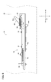
- FIG. 1 is a partially omitted perspective view of a medical manipulator according to an embodiment of the present invention.
- FIG. 2 is a partially omitted perspective view of a manipulator body in the medical manipulator shown in FIG. 1. It is a perspective view of the drive unit in the medical manipulator shown in FIG. It is a perspective view of a frequency limiting mechanism. It is a disassembled perspective view of a frequency limiting mechanism. It is a figure of the state which the slider advanced in the frequency limiting mechanism.
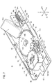
- FIG. 6 is a perspective view of a state where a mounting prevention function is activated in the number limiting mechanism.
- FIG. 11 is a side view of a state where a mounting prevention function is activated in the number limiting mechanism.
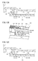
- FIG. 11A is a schematic cross-sectional view of the number limiting mechanism according to the modified example when the drive unit is mounted
- FIG. 11B illustrates the operation of the second claw member when the rack member moves forward in the number limiting mechanism according to the modified example
- FIG. 11C is a second diagram for explaining the operation of the second claw member when the rack member moves forward in the number limiting mechanism according to the modified example
- FIG. 12A is a schematic cross-sectional view for explaining the operation of the number limiting mechanism according to the modification example when the drive unit is removed, and FIG.
- FIG. 12B is the second claw member of the number limiting mechanism according to the modification example when the drive unit is removed.
- FIG. 12C is a diagram illustrating the operation of the first claw member of the number limiting mechanism according to the modification when the drive unit is removed. It is a typical perspective view which shows the structural example which provided the gear member in the frequency
- FIG. 14A is a schematic cross-sectional view illustrating a configuration example in which a lock member is provided in the number limiting mechanism according to the modified example
- FIG. 14B is a schematic diagram illustrating a state in which the lock member is activated in the number limiting mechanism according to the modified example. It is sectional drawing. It is a partially-omission perspective view of the medical manipulator concerning other embodiments of the present invention.
- FIG. 16 is a partially omitted perspective view of the manipulator body in the medical manipulator shown in FIG. 15.
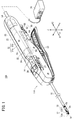
- FIG. 1 is a partially omitted perspective view of a medical manipulator 10A (hereinafter abbreviated as “manipulator 10A”) according to an embodiment of the present invention.
- the manipulator 10A is a medical device for holding a needle, a thread, or a part of a living body with a gripper 12 (end effector) provided at the tip or touching the living body to perform a predetermined treatment.
- the manipulator 10 ⁇ / b> A drives a handle 14 provided with a plurality of input operation units, a shaft 16 extending from the handle 14, a tip operating unit 18 including a gripper 12 provided at the tip of the shaft 16, and the tip operating unit 18. And a drive unit 22 that is provided with a motor 20 (drive source) to be attached to and detachable from the handle 14.
- the handle 14, the shaft 16, and the distal end working unit 18 constitute a manipulator body 11 ⁇ / b> A.
- the X direction in the figure is the front-rear direction
- the Y direction is the left-right direction
- the Z direction is the up-down direction.
- the X1 direction is the front and the X2 direction is the rear.
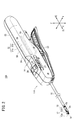
- the manipulator body 11A and the drive unit 22 are detachable. In a state where the drive unit 22 is removed from the manipulator body 11A (see FIG. 2), the driving force of the motor 20 is not transmitted to the distal end working unit 18. On the other hand, when the motor 20 is driven with the drive unit 22 attached to the handle 14, the driving force of the motor 20 is transmitted to the distal end working unit 18.
- the manipulator 10A shown in FIG. 1 is configured as a needle driver in which the gripper 12 at the tip can hold a medical needle (curved needle or the like).
- the gripper 12 is a part for performing a surgical procedure.
- the gripper 12 includes first and second gripper members 12a and 12b, and is configured to open and close based on a predetermined opening and closing operation axis Og.
- the gripper 12 is configured such that the first gripper member 12a is configured as a fixed portion and the second gripper member 12b is configured as a movable portion, but both gripper members 12a and 12b are configured as movable portions. Also good.
- the tip operating unit 18 including the gripper 12 can be changed in posture with respect to the shaft 16 with a plurality of degrees of freedom.
- the distal end working unit 18 tilts left and right with respect to the axis of the shaft 16 with respect to the tilting axis Oy, and the longitudinal axis of the distal end working unit 18 (swing motion). It is possible to perform a “roll operation” that rotates about the roll axis Or).
- the tilt axis Oy is not limited to being set in the vertical direction, and may be set in another direction that intersects the axis of the shaft 16.
- the shaft 16 is a long and thin tubular member, and connects the handle 14 and the distal end working unit 18. In FIG. 1, a part of the shaft 16 is omitted and is drawn shorter than the actual one.
- the hollow portion of the shaft 16 is provided with a power transmission mechanism for transmitting power necessary for opening / closing the gripper 12 and roll operation and tilting operation of the distal end working unit 18 from the handle 14 side to the distal end working unit 18.
- a plurality of constituent members are inserted and arranged.
- the shaft 16 may be configured such that one or more joints are provided in the middle of the longitudinal direction of the shaft 16 and the tilting operation can be performed at the joints. Moreover, the roll operation
- movement may be comprised in the middle part of the longitudinal direction of the shaft 16, or the base end part of the shaft 16.
- the handle 14 is gripped by an operator when the manipulator 10A is used, and is operated by touching an input operation unit (in this embodiment, a tilting wheel 26, a roll switch 28, and a lever 30 described later) with fingers. This is a portion that drives the distal end working portion 18 connected to the distal end portion of the shaft 16.
- an input operation unit in this embodiment, a tilting wheel 26, a roll switch 28, and a lever 30 described later
- the handle 14 includes a body portion 24 to which the base end of the shaft 16 is connected, a tilting wheel 26 that is provided on the body portion 24 and forms a tilt operation portion, and a roll that is provided on the body portion 24 and forms a roll operation portion.
- a switch 28 and a lever 30 provided in the body portion 24 and constituting an opening / closing operation portion are provided.
- the body portion 24 is a portion that is gripped by the user when the manipulator 10 is used.
- the trunk portion 24 is configured in a stick shape extending slightly longer in the axial direction of the shaft 16.
- the body portion 24 includes a housing 32 composed of a left cover 32a and a right cover 32b, and a frame, driving components (pulleys, gears, wires, etc.) and the like are disposed in the housing 32.
- a mounting hole 33 opened rearward is formed in order to insert and mount the drive unit 22 from the rear.
- the tilting wheel 26 for tilting the distal end working unit 18 is provided in the vicinity of the longitudinal center of the body unit 24 so as to be rotatable about the vertical axis of the handle 14.
- the tilting wheel 26 is configured as a manual operation unit, and the tilting wheel 26 is partially exposed from the openings 27 provided on the left and right sides of the housing 32.
- the tilting wheel 26 When the tilting wheel 26 is rotationally operated, the operating force is mechanically transmitted to the tip operating unit 18 via the power transmission system for tilting operation provided in the handle 14 and the shaft 16, and the tip operating unit 18 is It tilts around an axis (inclination axis Oy) in a direction non-parallel to the axis of the shaft 16. Specifically, when the tilting wheel 26 is rotated clockwise in plan view, the distal end working unit 18 tilts to the right with reference to the handle 14, and when the tilting wheel 26 is rotated counterclockwise in plan view. The distal end working unit 18 tilts leftward with respect to the handle 14.
- the roll switch 28 for causing the tip operating portion 18 to roll is provided on the upper portion of the body portion 24 near the tip.
- the roll switch 28 is configured as an electric operation unit that gives an operation command to the motor 20 via the controller 36.
- the drive unit 22 When the drive unit 22 is attached to the handle 14 and the controller 36 is turned on, if the roll switch 28 is operated and moved, the operation state (position) of the roll switch 28 is detected by the controller 36, and the controller The motor 20 is driven under the control action of 36, and the driving force of the motor 20 is transmitted to the distal end working unit 18, so that the distal end working unit 18 sets the longitudinal axis of the distal end working unit 18 (roll axis Or). Rotates as the center.
- a lever 30 for opening and closing the gripper 12 is provided at the lower portion of the body portion 24 so as to be swingable up and down with the tip side as a fulcrum.
- the lever 30 is configured as a manual operation unit, and the operation force on the lever 30 is mechanically transmitted to the gripper 12 of the distal end working unit 18, so that the gripper 12 is opened and closed.
- the gripper 12 is opened with the lever 30 opened, and the gripper 12 is closed when the lever 30 is closed.
- the manipulator 10 ⁇ / b> A is used in a state where the drive unit 22 is connected to the controller 36 via a cable 54.
- the controller 36 supplies power to the motor 20 and controls driving, and receives power from an external power source.
- the controller 36 controls the driving of the motor 20 in accordance with the operation.
- the rotation of the motor 20 may be detected and feedback control may be performed through the controller 36.
- the manipulator 10A configured as described above is discarded after being used a predetermined number of times for the manipulator body 11A, while the drive unit 22 is used many times by changing the connected manipulator body 11A. Can be taken.
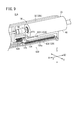
- FIG. 3 is a perspective view of the drive unit 22.
- the drive unit 22 includes a housing 48, a motor 20 (drive source) disposed in the housing 48, and a drive coupling 50 (drive member) fixed to the output shaft 21 of the motor 20.
- a cable 54 including a power line and a signal line is connected to the base end side of the drive unit 22.
- the drive coupling 50 fixed to the output shaft 21 of the motor 20 is a driven coupling (driven member) (not shown) provided on the handle 14 side. To fit (mesh).
- the motor 20 is driven in a state where the drive coupling 50 and the driven coupling are fitted, the rotational driving force of the motor 20 is transmitted to the handle 14 side via the drive coupling 50 and the driven coupling.
- the handle 14 is provided with a guide rail 56 extending along the longitudinal direction (front-rear direction) of the handle 14.
- guide rails 56 are provided on both the left and right sides of the inner surface of the housing 32.
- groove-shaped guide receiving portions 58 extending along the longitudinal direction of the drive unit 22 are provided on the left and right side surfaces of the housing 48.
- the guide rail 55 and the guide receiving portion 58 constitute a guide mechanism 55 (see FIG. 1).
- the drive unit 22 can be smoothly moved with respect to the handle 14 under the action of the guide mechanism 55. Therefore, the drive unit 22 can be reliably and easily attached to the handle 14 with an accurate positional relationship.
- the handle 14 is provided with a handle side terminal.
- the drive unit 22 is provided with a unit side terminal. In a state where the drive unit 22 is attached to the handle 14, the handle side terminal and the unit side terminal are in contact with each other. With this configuration, the operation state of the roll switch 28 is detected by the controller 36, and the controller 36 can appropriately drive and control the motor 20.
- the drive unit 22 is provided with a lock mechanism 60 that restricts the drive unit 22 from being detached from the handle 14 in a state where the drive unit 22 is attached to the handle 14.
- the lock mechanism 60 of the illustrated example includes an engaging portion 62 provided on the handle 14 and a lever device 64 provided on the drive unit 22.
- the lever device 64 includes a lever device 64, an operation tab 68, and a lever urging member (not shown).
- the lever member 66 can swing with respect to the housing 48 and is provided with an engaging claw 67.
- the operation tab 68 is provided at the base end of the lever member 66.
- the lever urging member elastically urges the lever member 66 toward the protruding direction of the engaging claw 67 (downward in the illustrated example).
- the engagement claw 67 provided on the lever member 66 engages with the engagement portion 62 provided in the handle 14, thereby driving the handle 14. The separation of the unit 22 is prevented. On the other hand, when the engagement between the engagement claw 67 of the lever member 66 and the engagement portion 62 is released, the drive unit 22 can be detached from the handle 14.
- the handle 14 is further provided with a number limiting mechanism 70.
- the number limiting mechanism 70 prevents the drive unit 22 from being attached to the handle 14 when the number of times the drive unit 22 is attached to or detached from the handle 14 reaches a set number.
- the set number of times is a use limit number of the manipulator body 11A.
- the case where the drive unit 22 is attached / detached once to / from the manipulator body 11A is regarded as one use of the manipulator body 11A.
- the set number of times that the mounting of the drive unit 22 is prevented can be arbitrarily set, but is set, for example, in the range of 10 to 50 times.
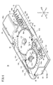
- FIG. 4 is a perspective view of the number limiting mechanism 70 according to one configuration example
- FIG. 5 is an exploded perspective view of the number limiting mechanism 70.
- the number limiting mechanism 70 includes a frame 72, an operating body 74 that can slide in the front-rear direction with respect to the frame 72, an intermediate transmission mechanism 76 that is linked to the operating body 74, A rotating body 78 that is rotated by the intermediate transmission mechanism 76 and a stopper 80 that can be changed between a non-restricted state and a restricted state and that prevents the drive unit 22 from being attached to the handle 14 in the restricted state.
- the frame 72 has a frame main body 82 and a cover body 84 fixed to the frame main body 82, and is fixed at a predetermined position in the handle 14.
- the frame main body 82 in the illustrated example has a substantially rectangular shape in plan view.
- An operating body 74, an intermediate transmission mechanism 76, a rotating body 78, and a stopper 80 are arranged on the frame 72.
- the cover body 84 is fixed to the frame main body 82 by appropriate fixing means 85 (screws in the illustrated example). Both the frame main body 82 and the cover body 84 can be manufactured by sheet metal processing, for example.
- the frame main body 82 and the cover body 84 may be made of resin.
- the operating body 74 is mechanically interlocked with the attachment / detachment of the drive unit 22 with respect to the handle 14. Specifically, the actuating body 74 is pushed by the drive unit 22 as the drive unit 22 is attached to the handle 14 and is displaced from the retracted position (first position) to the advanced position (second position). To do. Further, the operating body 74 returns from the forward movement position to the backward movement position as the drive unit 22 is removed from the handle 14. In FIG. 4, the actuator 74 is in the retracted position.
- the operating body 74 of the illustrated example is configured as a slider 74A that moves forward and backward as the drive unit 22 is attached to and detached from the handle 14.
- the operating body 74 has a flat plate-like base portion 86 that contacts the frame main body 82 and is slidable along the frame main body 82, and a pressed portion 88 that protrudes from the base portion 86.
- the base 86 is provided with a plurality of (two in the illustrated example) elongated hole-shaped guide holes 90a and 90b extending in the front-rear direction.
- Guide pins 92a and 92b are fixed to the frame body 82, and the guide pins 92a and 92b are inserted into the guide holes 90a and 90b.
- the guide pins 92a and 92b are prevented from coming out of the guide holes 90a and 90b.
- the operating body 74 can slide stably with respect to the frame 72 in the front-rear direction (X direction) by the guide action by the engagement between the guide holes 90a, 90b and the guide pins 92a, 92b.
- the pressed portion 88 is a portion that is pressed by the drive unit 22 as the drive unit 22 moves when the drive unit 22 is attached to the handle 14.
- the pressed portion 88 is provided to bend at the tip of the base 86 and protrude upward.
- the pressed portion 88 may be provided integrally with the base 86, or may be a member attached to the base 86.
- the operating body 74 is elastically biased toward the retracted position by a return spring 94 (operating body biasing means).
- a return spring 94 operating body biasing means
- one end 94 a of the return spring 94 is engaged with a hook piece 75 provided on the operating body 74
- the other end 94 b of the return spring 94 is engaged with a hook piece 73 provided on the frame 72.
- the return spring 94 urges the operating body 74 backward (X2 direction) with respect to the frame 72 by an elastic action to be contracted.
- the return spring 94 may be configured and arranged so as to urge the operating body 74 rearward with respect to the frame 72 by an elastic action to be extended.
- the intermediate transmission mechanism 76 includes a claw member 98 that is displaced together with the operating body 74, a ratchet wheel 100 that is driven by the claw member 98, a first gear 102 that is coupled to the ratchet wheel 100, and a second gear that meshes with the first gear 102. And a gear 104.
- the claw member 98 is formed in a plate shape and is supported by a shaft portion 117 fixed to the base portion 86, and can rotate (swing) around the shaft portion 117 within a predetermined angle range with respect to the operating body 74. It is. By attaching a locking part 118 (C clip in the illustrated example) to the shaft portion 117, the claw member 98 is prevented from coming off from the shaft portion 117.
- the claw member 98 is provided with an engagement claw 98 a that can be engaged with the ratchet wheel 100, and a contact protrusion 98 b that can contact a locking piece 99 provided on the base 86.
- the claw member 98 is elastically urged in the direction A in FIG. 5 by the claw urging member 108.
- the claw urging member 108 in the illustrated example is in the form of a torsion spring, but may be a spring of another form such as a coil spring or may be constituted by an elastic member other than the spring.
- the claw member 98 is prevented from further rotating in the A direction.
- the claw member 98 receives a predetermined force or more in the B direction opposite to the A direction, the claw member 98 can rotate in the B direction against the elastic force of the claw urging member 108. It is.
- the ratchet wheel 100 is provided to be rotatable with respect to the frame 72 via the shaft portion 101.
- the ratchet wheel 100 of the illustrated example is configured in a relatively thin flat plate shape.
- a latching component 119 (C clip in the illustrated example) is attached to the shaft portion 101 to prevent the ratchet wheel 100 and the first gear 102 from coming off from the shaft portion 101.
- the shaft portion 101 is fixed to the cover body 84 by a fixing component 97 (in the illustrated example).
- the teeth 100 a provided on the outer periphery of the ratchet wheel 100 can be engaged with the engaging claws 98 a of the claw member 98.
- a latch member 114 provided on the frame main body 82 is engaged with the teeth 100 a of the ratchet wheel 100.
- the latch member 114 is fixed to the frame main body 82 by fixing means 116 (screws in the illustrated example).
- the latch member 114 is provided with an elastically displaceable latch piece 115.
- the latch piece 115 engages with the teeth 100a of the ratchet wheel 100 so as to allow the ratchet wheel 100 to rotate in the C direction while preventing the ratchet wheel 100 from rotating in the direction opposite to the C direction. That is, the ratchet wheel 100 can rotate only in the C direction.
- the first gear 102 is arranged coaxially with the ratchet wheel 100.
- the second gear 104 in the illustrated example is configured in a relatively thin flat plate shape.
- the ratchet wheel 100 and the first gear 102 are fixed to each other so as not to be relatively rotatable.
- the two holding pins 103 are inserted into and engaged with both the ratchet wheel 100 and the first gear 102 so that the ratchet wheel 100 and the first gear 102 are not relatively rotatable. .
- the first gear 102 rotates integrally with the ratchet wheel 100. Therefore, like the ratchet wheel 100, the first gear 102 can rotate only in the C direction.
- the second gear 104 is provided to be rotatable with respect to the frame 72 via the shaft portion 105.
- the second gear 104 in the illustrated example is configured in a relatively thin flat plate shape.
- a locking part 133 C clip in the illustrated example
- the teeth 102 a provided on the outer peripheral portion of the first gear 102 mesh with the teeth 104 a provided on the outer peripheral portion of the second gear 104. Accordingly, the second gear 104 rotates in the D direction about the shaft portion 105 as the first gear 102 rotates in the C direction.
- a ring-shaped spacer 113 is disposed between the second gear 104 and the frame body 82.
- the rotating body 78 is arranged coaxially with the second gear 104 and is arranged on the lower surface side of the frame body 82 in the illustrated example. Further, the rotating body 78 in the illustrated example is configured in a relatively thin flat plate shape.
- the second gear 104 and the rotating body 78 are fixed to each other via the shaft portion 105 so as not to be relatively rotatable, and the rotating body 78 rotates integrally with the second gear 104.
- the rotating body 78 has a disk shape larger in diameter than the second gear 104, and a notch 79 is provided in a part of the outer peripheral portion in the circumferential direction.
- the ratchet wheel 100, the first gear 102, the second gear 104, and the rotating body 78 described above constitute a counting mechanism 112 that operates a predetermined amount each time the operating body 74 is operated.
- the stopper 80 operates from a non-restricted state (the state shown in FIG. 4) that allows the drive unit 22 to be attached to the handle 14 to a restricted state (the position shown in FIG. 7) that prevents the drive unit 22 from being attached to the handle 14.
- the stopper 80 in the illustrated example is rotatably supported by a shaft portion 77 inserted into a stopper support member 81 fixed to the frame 72 (frame body 82).
- a locking part 134 (C clip in the illustrated example) is attached to the shaft part 77, thereby preventing the shaft part 77 from coming off from the stopper support member 81.
- the stopper 80 is in a “non-restricted state” when it is tilted substantially parallel to the frame main body 82, and is a “restricted state” when it occurs at a certain tilt angle with respect to the frame main body 82.
- the stopper 80 protrudes on the movement path (inside the mounting hole 33) of the drive unit 22 when the drive unit 22 is mounted on the handle 14 in the restricted state.
- the stopper 80 is provided with a contact body 80b that can be engaged with the rotating body 78.
- the abutting body 80 b in the illustrated example protrudes downward from the distal end side of the stopper 80 and is inserted into a hole 82 a provided in the frame main body 82.
- the stopper 80 is always urged elastically by the stopper urging member 110 in the direction of the restricted state.
- the stopper urging member 110 in the illustrated example is configured by a leaf spring disposed between the stopper 80 and the stopper support member 81, but may be configured by a spring of another form such as a coil spring. The elastic member other than the spring may be used.
- the stopper 80 is kept in a non-regulated state against the elastic force (biasing force) of the stopper urging member 110.
- the position (phase) of the notch 79 of the rotating body 78 coincides with the abutment 80b, whereby the abutment 80b enters the notch 79.
- the stopper 80 tilts and changes to a restricted state.
- the stay member 135 is fixed to the lower part of the frame body 82.
- the stay member 135 supports a portion of the rotating body 78 that is pressed by the contact body 80b from below. Since the rotating body 78 is supported from below by the stay member 135, the rotating body 78 does not tilt even when the contact body 80b presses the rotating body 78.
- the stay member 135 is provided with a notch 135a that allows the contact body 80b to enter.
- the notch 135 a is provided at a position corresponding to the hole 82 a of the frame main body 82. Thereby, when the notch 79 of the rotating body 78 comes to the position of the contact body 80b, the change of the stopper 80 from the non-regulated state to the regulated state is not hindered.
- the manipulator 10A according to the present embodiment is basically configured as described above, and the operation and effect will be described next.
- the number limiting mechanism 70 is in the initial state shown in FIG.
- the notch 79 provided in the rotating body 78 is in the direction in which the rotating body 78 can rotate from the contact body 80b of the stopper 80 by the amount corresponding to the set number of times (the number of times of use limit). It is in a position shifted in the opposite direction to the (D direction).
- the contact body 80b is locked by the rotating body 78, and the stopper 80 is held in a collapsed state, that is, an unregulated state.
- the operating body 74 is held in the retracted position by the elastic force of the return spring 94.
- the pressed portion 88 of the operating body 74 is caused by a part of the drive unit 22 (for example, the front end portion of the housing 48). It is pressed forward (X1 direction). Thereby, as shown in FIG. 6, the operating body 74 moves to the advance position. As the operating body 74 advances, the claw member 98 provided on the operating body 74 also advances. The engaging claw 98 a of the claw member 98 that moves forward pushes the teeth 100 a of the ratchet wheel 100. As a result, the ratchet wheel 100 is rotated in the C direction by one tooth. When the ratchet wheel 100 rotates, the latch piece 115 gets over the teeth 100a of the ratchet wheel 100 by one tooth with elastic deformation.
- the first gear 102 also rotates in the C direction.
- the second gear 104 that meshes with the first gear 102 rotates in the D direction
- the rotating body 78 that is coaxially connected to the second gear 104 also rotates in the D direction.
- the notch 79 provided in the rotating body 78 is displaced by a predetermined amount in the D direction.
- the contact body 80b of the stopper 80 remains in contact with the outer peripheral portion of the rotating body 78, so that the stopper 80 is still held in an unregulated state.
- the operating body 74 When removing the drive unit 22 from the handle 14, the operating body 74 returns to the retracted position. That is, as the drive unit 22 moves rearward (X2 direction), the pressing of the pressed unit 88 by the drive unit 22 is released, so that the operating body 74 is moved rearward by the elastic force of the return spring 94. . As the actuating body 74 moves rearward, the teeth 100a of the ratchet wheel 100 are pushed backward by the claw member 98 provided on the actuating body 74. However, the latching action of the latch piece 115 causes the ratchet wheel 100 to move in the C direction. Rotation in the opposite direction is prevented. For this reason, when the operating body 74 moves backward, the notch 79 provided in the rotating body 78 does not return to the original position.
- the claw member 98 rotates in the B direction against the elastic force of the claw urging member 108 in the A direction, so that the teeth 100a of the ratchet wheel 100 are equivalent to one tooth. Just get over.
- the engaging claw 98a of the claw member 98 gets over the tooth 100a of the ratchet wheel 100 by one tooth, the claw member 98 is rotated in the A direction by the elastic force of the claw urging member 108, and the contact protrusion 98b. It stops at the position where the locking piece 99 comes into contact.
- the above operation is repeated each time the drive unit 22 is attached to and detached from the handle 14 until a predetermined set number of times (the number of times the manipulator body 11A is used) is reached. Therefore, every time the drive unit 22 is attached or detached, the notch 79 provided in the rotating body 78 moves by a predetermined amount in the C direction.
- the drive unit 22 is repeatedly attached to and detached from the handle 14, and when the number of attachments / detachments reaches the set number of times and the notch 79 reaches the position of the contact body 80b of the stopper 80, the displacement restriction on the stopper 80 by the rotating body 78 is performed. Is released. Accordingly, as the contact body 80b enters the notch 79, the stopper 80 rises obliquely and reaches a restricted state, as shown in FIGS. In FIG. 8, the stopper 80 in the non-regulated state is indicated by a virtual line (two-dot chain line).
- the stopper 80 protrudes on the movement path of the drive unit 22 when the drive unit 22 is mounted on the handle 14 (in the mounting hole 33 in the illustrated example) in the restricted state. Therefore, even if the drive unit 22 is to be attached to the handle 14 in this state, the drive unit 22 contacts the stopper 80 while the drive unit 22 is moved in the distal direction with respect to the handle 14. For this reason, the drive unit 22 cannot be moved further forward. As a result, the mounting of the drive unit 22 to the handle 14 is prevented.
- the drive unit 22 when the number of times the drive unit 22 is attached to and detached from the handle 14 reaches the set number of times (the number of times the manipulator body 11A can be used), the drive unit 22 is removed from the handle 14. Can no longer be installed. That is, the use of the manipulator body 11A exceeding the usage limit number can be forcibly limited.
- the number limiting mechanism 70 includes an operating body 74 and a count mechanism 112, and prevents the drive unit 22 from being attached to the handle 14 when the count mechanism 112 operates a set number of times from the initial state. To do. According to this configuration, by providing the operating body 74 and the counting mechanism 112 that are mechanically interlocked with the attachment / detachment of the drive unit 22, the number of attachments / detachments is reliably counted. Therefore, when the set number of times is reached, the attachment prevention function can be surely activated.
- the stopper 80 protrudes on the movement path of the drive unit 22 when the drive unit 22 is attached to the handle 14 in the restricted state. According to this configuration, even if the drive unit 22 is to be mounted on the handle 14 while the stopper 80 is in a restricted state, the drive unit 22 is caught by the stopper 80, so that the mounting of the drive unit 22 is physically blocked. Therefore, it is possible to reliably prevent the use of the manipulator body 11A exceeding the usage limit number.
- the operating body 74 is configured as a slider 74A that moves forward and backward as the drive unit 22 is attached to and detached from the handle 14. According to this configuration, attachment / detachment of the drive unit 22 can be detected mechanically and reliably, and the count mechanism 112 can be operated.
- the count mechanism 112 can be reliably operated by a predetermined amount each time the drive unit 22 is attached or detached.
- the operating body 74 is mechanically interlocked by attaching and detaching the drive unit 22, and the movement of the operating body 74 is transmitted to the rotating body 78 via the intermediate transmission mechanism 76.
- the stopper 80 is in a restricted state protruding on the movement path of the drive unit 22. Even if the drive unit 22 is to be attached to the handle 14 in this state, the drive unit 22 is caught by the stopper 80, so that the attachment of the drive unit 22 is physically blocked. Therefore, it is possible to reliably prevent the use of the manipulator body 11A exceeding the usage limit number.
- each of the operating body 74, the intermediate transmission mechanism 76, and the rotating body 78 is formed by a plate-like member, and the stopper 80 is changed from the non-regulated state to the regulated state with an inclination operation from the initial posture. Change.
- the number limiting mechanism 70 can be reduced in thickness, and the installation volume in the handle 14 can be reduced. Therefore, an increase in the size of the handle 14 associated with the provision of the number limiting mechanism 70 can be suppressed.
- the intermediate transmission mechanism 76 includes a plurality of gears (first gear 102 and second gear 104) that mesh with each other. According to this configuration, the amount of rotation of the rotating body 78 according to the amount of displacement of the operating body 74 when the drive unit 22 is attached to and detached from the handle 14 can be adjusted by the gear ratio of the gear. Therefore, it is possible to easily set the number of times (setting number) of activating the attachment prevention function by adjusting the gear ratio.
- the contact member 80b provided on the stopper 80 abuts against the rotating body 78 in a state where the number of attachments / detachments is less than the set number of times, so that the stopper 80 resists the urging force of the stopper urging member 110. Is held in an unregulated state.
- the contact body 80 b provided on the stopper 80 can enter the notch 79 in a state where the number of attachments / detachments has reached the set number. According to this configuration, it is possible to simply configure a mechanism that does not operate the stopper 80 when the number of attachments / detachments is less than the set number, and operates the stopper 80 when the predetermined number of times is reached.
- the number limiting mechanism 120 may be employed instead of the number limiting mechanism 70.
- the number limiting mechanism 120 is provided on the handle 14 and prevents the drive unit 22 from being attached to the handle 14 when the number of times the drive unit 22 is attached to and detached from the handle 14 reaches a set number.
- the number limiting mechanism 120 includes an operating body 122 that is slidable in the front-rear direction with respect to the handle 14, a first claw member 124 that is swingable with respect to the operating body 122, and the operating body 122.
- the first urging member 126 that elastically urges the first claw member 124, the linear rack member 128 that engages with the first claw member 124, and the surface that the first claw member 124 engages with. It has the 2nd claw member 130 engaged with the rack member 128 in a different surface, and the 2nd energizing member 132 which energizes the 2nd claw member 130 elastically.
- the operating body 122 mechanically interlocks with the attachment / detachment of the drive unit 22 with respect to the handle 14. Specifically, the actuating body 122 of the illustrated example is pushed by the drive unit 22 as the drive unit 22 is attached to the handle 14 and moved from the retracted position (first position) to the advanced position (second position). Position). The operating body 122 is configured to return from the forward movement position to the backward movement position when the drive unit 22 is removed from the handle 14. 9 and 10, the operating body 122 is in the retracted position.
- the operating body 122 is configured as a slider 122A that moves forward and backward as the drive unit 22 is attached to and detached from the handle 14.
- the actuating body 122 of the illustrated example is provided with a stepped pressed portion 123.
- the operating body 122 is always elastically urged toward the rear (X2 direction) by the first urging member 126.
- the first claw member 124 can swing with respect to the operating body 122 via the shaft portion, and a portion below the swing center is always elastically attached to the rear by the first biasing member 126. Be forced.
- a first engagement claw 125 is provided on the first claw member 124.
- the rack member 128 is disposed so as to be slidable in the front-rear direction (X direction) of the handle 14.
- the rack member 128 is provided with first teeth 128a (see FIGS. 9 and 10) and second teeth 128b (see FIG. 11B).
- the first teeth 128 a are provided on the top surface of the rack member 128, and the second teeth 128 b are provided on the side surface of the rack member 128.
- the first engagement claw 125 of the first claw member 124 is engaged with the first teeth 128a of the rack member 128.
- the rack member 128 constitutes a counting mechanism 129 that operates a predetermined amount each time the operating body 122 operates.
- the second claw member 130 is provided in the handle 14 so as to be swingable through a shaft portion.
- a second engagement claw 131 is provided on the second claw member 130.
- the second engaging claws 131 engage with the second teeth 128b of the rack member 128.
- the second urging member 132 elastically urges the second claw member 130 toward the rack member 128 side.
- the number limiting mechanism 120 is in the initial state shown in FIG.
- the drive unit 22 is mounted on the handle 14 of the unused manipulator body 11A, the pressed portion 123 of the operating body 122 is moved forward by a part of the drive unit 22 (the front end portion of the housing 48). Pressed.
- the operating body 122 moves to the advanced position.
- the first claw member 124 provided on the operating body 122 also advances.
- the first engaging claw 125 of the first claw member 124 that moves forward pushes the first teeth 128a of the rack member 128 forward (X1 direction).
- the rack member 128 is advanced by one tooth.
- the second claw member 130 engaged with the second tooth 128 b is inclined against the elastic force of the second urging member 132.
- FIG. 11C when the rack member 128 moves forward by one tooth, the second engaging claw is returned to the initial position by the elastic action of the second urging member 132.
- the operating body 122 When removing the drive unit 22 from the handle 14, the operating body 122 returns to the retracted position. That is, as the drive unit 22 moves rearward, the pressing of the pressed unit 123 by the drive unit 22 is released, so that the operating body 122 is moved backward by the elastic force of the first biasing member 126.
- the first claw member 124 In the process of moving the operating body 122 backward, as shown in FIG. 12A, the first claw member 124 is also moved rearward, but the first engagement claw 125 is pushed by the first teeth 128 a of the rack member 128. Therefore, the first claw member 124 rotates. At this time, as shown in FIG. 12B, the second engaging claw 131 of the second claw member 130 and the second tooth 128b of the rack member 128 are engaged with each other, so that the rack member 128 does not return backward. .
- the above operation is repeated each time the drive unit 22 is attached to and detached from the handle 14 until a predetermined set number of times (the number of times the manipulator body 11A is used) is reached. Therefore, each time the drive unit 22 is attached or detached, the rack member 128 moves forward. Then, the drive unit 22 is repeatedly attached to and detached from the handle 14, and when the number of attachments and detachments reaches the set number, a part of the rack member 128 (for example, the front end) comes into contact with the wall in the handle 14 and the rack 14 The member 128 can no longer advance.
- a gear member 136 (a reduction mechanism) having a plurality of gear portions (a first gear portion 137 and a second gear portion 138) is disposed between the first claw member 124 and the rack member 128. .
- the second gear portion 138 has a smaller diameter than the first gear portion 137.
- the first engagement claw 125 of the first claw member 124 and the first gear portion 137 of the gear member 136 are engaged with each other.
- the second gear portion 138 of the gear member 136 and the first teeth 128a of the rack member 128 mesh with each other.
- the gear member 136 rotates as the first claw member 124 moves forward.
- the rotation of the gear member 136 is converted into a linear motion backward (X2 direction) of the rack member 128 via the second gear portion 138 and the first teeth 128a.
- the second gear portion 138 has a smaller diameter than the first gear portion 137, the speed reducing action is performed, so the linear displacement amount (absolute value) of the rack member 128 is the straight line of the first claw member 124. It is smaller than the displacement (absolute value). Therefore, it is easy to ensure the stroke of the rack member 128 from the initial position to the set number of times.
- the second engagement claw 131 of the second claw member 130 and the second teeth 128b of the rack member 128 may mesh with each other.
- the first gear portion 137 of the gear member 136 and the second engagement claw 131 of the second claw member 130 are engaged with each other, thereby providing a function of preventing the rack member 128 from returning backward. Also good.
- the lock member 142 is pressed against the rack member 128 by the biasing member 140 (spring or the like) before the number of attachments / detachments reaches the set number.
- the rack member 128 advances, and when the rack member 128 advances to a position where the number of attachments / detachments reaches the set number, the lock member 142 is released from the rack member 128.
- the lock member 142 is displaced toward the operating body 122 by the elastic force of the biasing member 140 and engages with the operating body 122. In a state where the lock member 142 is engaged with the operating body 122, the movement of the operating body 122 in the X direction is prevented.
- the lock member 142 operates so as to protrude into the insertion opening of the drive unit 22 in the handle 14 when the number of attachments / detachments reaches the set number.
- a stopper 143 may be provided.
- the drive unit 22 configured as described above may be used by being mounted not only on the manipulator body 11A configured as a needle driver but also on the manipulator body 11B configured as an electric knife shown in FIGS. 15 and 16. it can.
- the combination of the manipulator main body 11B and the drive unit 22 constitutes an electrosurgical type medical manipulator 10B (hereinafter abbreviated as “manipulator 10B”) driven by the motor 20.
- the manipulator main body 11B includes a handle 150 provided with a plurality of input operation units, a shaft 152 extending from the handle 150, and a tip operation unit 156 including a gripper 154 (end effector) provided at the tip of the shaft 152. .
- the manipulator main body 11A shown in FIG. 1 has a stick shape (bar shape) as a whole and is suitable for use as a needle driver.
- a grip 157 projecting downward is provided at the lower part of the handle 150, and the handle 150 has a handgun shape as a whole and is suitable for use as an electric knife. It has a different shape.
- the handgun-shaped handle shape is also suitable for scissors, gripping, peeling, and the like.
- the gripper 154 is a part that can be opened and closed and cauterizes the living tissue by grasping the living tissue and energizing it.
- the gripper 154 of the illustrated example includes a first gripper member 154a and a second gripper member 154b that can swing in opposite directions with respect to the opening / closing operation axis Og.
- the manipulator body 11B may be configured as a bipolar electric knife that energizes the first gripper member 154a and the second gripper member 154b with different polarities, or the first gripper member 154a and the second gripper member 154b. You may comprise as a monopolar-type electric knife which energizes any one or both.
- the opening / closing operation of the gripper 154 is performed by mechanically transmitting an operation of a lever 158 provided on the handle 150 to the distal end operating unit 156 via an opening / closing drive transmission system (not shown). That is, in the illustrated example, the lever 158 is configured as a manual operation unit, and the opening / closing operation of the gripper 154 is not motor driving but manual driving based on the operating force of the operator.
- the lever 158 is provided so as to be displaceable in the front-rear direction with respect to the grip 157.
- the gripper 154 opens, and when the lever 158 is pulled rearward with respect to the grip 157, the gripper 154 is closed. It is like that.
- the manipulator 10B according to the combination of the manipulator main body 11B and the drive unit 22 can be used as an electric knife by connecting the energizing connector 160 to the handle 150.
- the energization connector 160 is connected to a high frequency power supply device (not shown) via an energization cable 162, and a high frequency voltage is energized to the gripper 154 by the high frequency power supply device.
- the tip operation unit 156 can be tilted in the left-right direction (yaw operation) by the bending portion 164 provided at the tip of the shaft 152.
- the bending portion 164 is formed by connecting a plurality of joint members 166 so as to be rotatable within a predetermined angle range. In the state where these joint members 166 are arranged coaxially, the bending portion 164 has a straight shape, but when the adjacent joint members 166 are inclined with respect to each other, the bending portion 164 has a curved shape as a whole.
- the tip movement unit 156 is tilted by the controller 36 driving and controlling the motor 20 based on an operation on a tilting switch 168 provided on the handle 150, and the driving force of the motor 20 is driven through the handle 150 and the shaft 152. This is done by being mechanically transmitted to 156. That is, in the illustrated example, the tilting switch 168 is configured as an electric operation unit, and the tilting operation of the tip operating unit 156 is performed by motor driving.
- the tip operating unit 156 can perform a roll operation around the roll axis Or in the tip side of the bending portion 164.
- the roll operation is performed by mechanically transmitting a rotation operation to a rotation knob 170 (input operation unit) provided on the handle 150 to the tip operation unit 156 via a roll drive transmission system (not shown). That is, in the illustrated example, the rotary knob 170 is configured as a manual operation unit, and the roll operation of the distal end operating unit 156 is not motor driven but manual driving based on an operator's operating force.
- a mounting hole 150a opened rearward is provided on the upper side of the handle 150, and the drive unit 22 can be inserted into the mounting hole 150a and mounted on the handle 150. That is, the drive unit 22 is detachable from the proximal end side of the handle 150.
- the operation tab 68 provided on the drive unit 22 can be operated by touching the operator through the openings 150b provided on the left and right side surfaces of the handle 150. Exposed.
- the handle 150 is provided with a guide rail 56, similar to the handle 14 in the manipulator body 11A. Accordingly, the drive unit 22 is smoothly moved with respect to the handle 150 under the action of the guide mechanism 55 (see FIG. 15) including the guide rail 56 and the guide receiving portion 58, and the drive unit 22 is accurately moved with respect to the handle 150. Can be reliably and easily mounted in a simple positional relationship.
- the handle 150 is provided with a driven coupling similar to the driven coupling provided on the handle 14 in the manipulator body 11A. Therefore, when the drive unit 22 is attached to the handle 150, the driving force of the motor 20 is reliably transmitted to the handle 150 side by the engagement of the drive coupling 50 and the driven coupling.
- the handle 150 is provided with a handle side terminal.
- the handle side terminal and the unit side terminal provided in the drive unit 22 come into contact with each other.
- the operation state of the tilting switch 168 is detected by the controller 36, and the controller 36 can appropriately drive and control the motor 20.
- the handle 150 is provided with an engaging portion 62 that can be engaged with the lever member 66 provided in the drive unit 22. Accordingly, when the drive unit 22 is attached to the handle 150, the drive unit 22 is prevented from moving in the proximal direction with respect to the handle 150 (becomes locked).
- the drive unit 22 can be attached to and detached from the manipulator body 11B (forceps portion) having different functions and shapes, and in the mounted state, the drive unit 22 transmits the driving force of the motor 20 to the handles 14, 150.
- the electrical connection between the handles 14 and 150 and the drive unit 22 and the movement prevention of the drive unit 22 with respect to the handles 14 and 150 are reliably achieved.
- the form of the manipulator main bodies 11A and 11B to which the drive unit 22 can be attached and detached is not limited to the above-described two forms (needle driver, electric knife), and other forms having different functions and shapes, such as hooks and grasping forceps Etc.
- a suction device, a cleaning device, an energy device, or the like may be used.
- the drive unit 22 can be easily and reliably attached to the handles 14 and 150 having different functions and shapes, and the input operation unit provided on the handles 14 and 150 is provided. Based on the operation of the roll switch 28 and the tilting switch 168, the motor 20 can be driven, and the distal end working unit 18 can be operated by the driving force.
- the drive unit 22 including the motor 20 can be attached to and detached from the handle 14, so that it is not necessary to provide a drive source for each handle 14 having a different function and shape. That is, the manipulators 10A and 10B of the present invention can be used by attaching the common drive unit 22 to the handles 14 and 150 that are configured in an appropriate shape according to the type of the end effector. Therefore, good operability can be obtained without increasing the cost of the manipulators 10A and 10B.
- the handle 150 of the manipulator body 11B is provided with the number limiting mechanism 70 shown in FIG. For this reason, when the number of times of attaching / detaching the drive unit 22 to / from the handle 150 reaches the set number of times (the use limit number of the manipulator body 11B), the drive unit 22 cannot be attached to the handle 150 due to the action of the number limit mechanism 70. That is, the use of the manipulator body 11B exceeding the usage limit number can be forcibly limited.
- a number limiting mechanism 120 may be provided in place of the number limiting mechanism 70.
- a number limiting mechanism 120 according to the modification shown in FIG. 9 or the like may be provided.
- the configuration example shown in FIG. 13 or the configuration examples shown in FIGS. 14A and 14B may be employed.
Abstract
A medical manipulator (10A) comprises: a manipulator body (11A) that has a handle (14); a drive unit (22) that can be detachably attached to the handle (14); and an attachment limiting mechanism (70) that is provided to the handle (14). When the number of times that the drive unit (22) has been attached to and detached from the handle (14) reaches a set number, the attachment limiting mechanism (70) prevents the mounting of the drive unit (22) to the handle (14) The attachment limiting mechanism (70) has a counting mechanism (112) and a stopper (80). The counting mechanism (112) counts the number of times that the drive unit (22) is attached and detached. When the count reaches a set number, the stopper (80) is made to protrude into a mounting hole (33) in the handle (14) so as to prevent the insertion of the drive unit (22) into the mounting hole (33).
Description
本発明は、駆動源を備えた医療用マニピュレータに関する。
The present invention relates to a medical manipulator having a drive source.
内視鏡下外科手術(又は腹腔鏡下手術とも呼ばれる。)においては、患者の腹部等に1つ又は複数の孔を開け、当該1つ又は複数の孔にトラカール(筒状の器具)を挿入する。その後、当該1つ又は複数のトラカールを通して、腹腔鏡(カメラ)と複数の鉗子を体腔内に挿入する。鉗子の先端部には、エンドエフェクタとして、生体組織等を把持するためのグリッパや、鋏、電気メスのブレード等が取り付けられている。
In endoscopic surgery (also called laparoscopic surgery), one or more holes are made in the patient's abdomen, and a trocar (tubular instrument) is inserted into the one or more holes. To do. Thereafter, a laparoscope (camera) and a plurality of forceps are inserted into the body cavity through the one or more trocars. A gripper, a scissors, a blade of an electric knife, and the like are attached to the distal end portion of the forceps as an end effector for gripping a living tissue or the like.
腹腔鏡と鉗子を体腔内に挿入したら、腹腔鏡に接続されたモニタに映る腹腔内の様子を見ながら鉗子を操作して手術を行う。このような手術方法は、開腹を必要としないため、患者への負担が少なく、術後の回復や退院までの日数が大幅に低減される。このため、このような手術方法は、適用分野の拡大が期待されている。
Once the laparoscope and forceps are inserted into the body cavity, the operation is performed by operating the forceps while observing the inside of the abdominal cavity reflected on the monitor connected to the laparoscope. Since such an operation method does not require laparotomy, the burden on the patient is small, and the number of days until recovery and discharge from the operation is greatly reduced. For this reason, such an operation method is expected to expand the application field.
トラカールから挿入される鉗子として、先端部に関節を持たない一般的な鉗子の他に、先端部に関節を有してエンドエフェクタのロール動作や傾動動作が可能な鉗子、いわゆる医療用マニピュレータの開発が行われている(例えば、特許第4391762号公報参照)。このような医療用マニピュレータによれば、体腔内で自由度の高い動作が可能であり、手技が容易となり、適用可能な症例が多くなる。
Development of so-called medical manipulators as forceps inserted from trocars, in addition to general forceps that do not have joints at the tip, and those that have joints at the tip and can roll and tilt the end effector (For example, see Japanese Patent No. 4391762). According to such a medical manipulator, an operation with a high degree of freedom is possible in the body cavity, the procedure becomes easy, and the number of applicable cases increases.
また、操作性の向上を図り、手技を容易化することを目的として、先端動作部の動作の一部又は全部を駆動源(モータ)により行う医療用マニピュレータも提案されている(例えば、特開2008-104854号公報参照)。この種の医療用マニピュレータでは、操作ボタンが設けられたハンドルに駆動源としてのモータが搭載され、当該ハンドルに対して、先端動作部及びシャフトを含む作業部(鉗子に相当する部分)が着脱可能となっている。作業部には、ニードルドライバ、電気メス等の複数種類があり、ハンドルには、異なる種類の作業部が選択的に着脱可能となっている。
In addition, for the purpose of improving operability and facilitating a procedure, a medical manipulator in which part or all of the operation of the distal end working unit is performed by a drive source (motor) has been proposed (for example, JP, A 2008-104854). In this type of medical manipulator, a motor as a drive source is mounted on a handle provided with an operation button, and a working portion (a portion corresponding to forceps) including a distal end working portion and a shaft can be attached to and detached from the handle. It has become. There are a plurality of types of working units such as a needle driver and an electric knife, and different types of working units can be selectively attached to and detached from the handle.
ところで、駆動源が設けられたハンドルに対して異なる種類の作業部を着脱できるように構成された医療用マニピュレータの場合、異なる種類のエンドエフェクタに対して、使用するハンドルは共通である。一方、エンドエフェクタの種類ごとにハンドルの形状を異ならせると、操作性の向上が期待できる。しかしながら、異なる種類のエンドエフェクタを有する作業部ごとに、駆動源を含む異なる形状のハンドルを用意した場合、医療用マニピュレータのコストが嵩むという問題がある。
By the way, in the case of a medical manipulator configured so that different types of working units can be attached to and detached from the handle provided with the drive source, the handle to be used is common to the different types of end effectors. On the other hand, if the shape of the handle is different for each type of end effector, operability can be improved. However, when a handle having a different shape including a drive source is prepared for each working unit having different types of end effectors, there is a problem that the cost of the medical manipulator increases.
このような問題に対処するため、例えば、エンドエフェクタの種類に応じて適切な形状に構成されたハンドルを含むマニピュレータ本体(鉗子部分)に対して、共通の駆動ユニットを装着できる構成を採用することが考えられる。一方で、このような構成において、マニピュレータ本体には、種々の動力伝達部品(例えば、歯車、ワイヤ等)が設けられることが想定されるが、これらの動力伝達部品には使用に伴って劣化等が生じる。このため、マニピュレータ本体の使用回数には一定の制限を設けることが望ましい。
In order to deal with such problems, for example, a configuration in which a common drive unit can be mounted on a manipulator body (forceps portion) including a handle configured in an appropriate shape according to the type of end effector is adopted. Can be considered. On the other hand, in such a configuration, it is assumed that the manipulator body is provided with various power transmission parts (for example, gears, wires, etc.). However, these power transmission parts are deteriorated with use. Occurs. For this reason, it is desirable to provide a certain limit on the number of times the manipulator body is used.
上記の課題を考慮し、本発明は、ハンドルごとに駆動源を設けることなく操作性を向上できるとともに、マニピュレータ本体の使用回数を制限することができる医療用マニピュレータを提供することを目的とする。
In view of the above problems, an object of the present invention is to provide a medical manipulator that can improve operability without providing a drive source for each handle and can limit the number of times the manipulator body is used.
上記の目的を達成するため、本発明の医療用マニピュレータは、ハンドルを有するマニピュレータ本体と、前記ハンドルに対して着脱可能であり、駆動源を含む駆動ユニットと、前記ハンドルに設けられ、前記ハンドルに対する前記駆動ユニットの着脱回数が設定回数に達した場合に、前記ハンドルに対する前記駆動ユニットの装着を阻止する回数制限機構と、を備えることを特徴とする。
In order to achieve the above object, a medical manipulator of the present invention includes a manipulator body having a handle, a detachable to the handle, a drive unit including a drive source, a handle provided on the handle, A number-of-times limiting mechanism that prevents the drive unit from being attached to the handle when the number of attachments / detachments of the drive unit reaches a set number.
上記の構成によれば、ハンドルに対する駆動ユニットの着脱回数が設定回数(マニピュレータ本体の使用制限回数)に達すると、回数制限機構の作用により、ハンドルに対して駆動ユニットを装着できなくなる。すなわち、使用制限回数を超えるマニピュレータ本体の使用を強制的に制限することができる。また、駆動源を含む駆動ユニットがハンドルに対して着脱可能であるため、異なる機能及び形状を有するハンドルごとに駆動源を設ける必要がない。すなわち、本発明の医療用マニピュレータは、エンドエフェクタの種類に応じて適切な形状に構成されたハンドルに対して、共通の駆動ユニットを装着して使用できる。従って、マニピュレータのコストを高騰させることなく、良好な操作性が得られる。
According to the above configuration, when the number of attachments / detachments of the drive unit to / from the handle reaches the set number (the manipulator body use limit number), the drive unit cannot be attached to the handle due to the action of the number limit mechanism. That is, the use of the manipulator body exceeding the usage limit number can be forcibly limited. Further, since the drive unit including the drive source is detachable from the handle, it is not necessary to provide a drive source for each handle having a different function and shape. That is, the medical manipulator of the present invention can be used by attaching a common drive unit to a handle configured in an appropriate shape according to the type of end effector. Therefore, good operability can be obtained without increasing the cost of the manipulator.
前記回数制限機構は、前記ハンドルに対する前記駆動ユニットの着脱に機械的に連動する作動体と、前記作動体が作動するたびに所定量ずつ動作するカウント機構とを有し、前記カウント機構が初期状態から前記設定回数分だけ動作した際に、前記ハンドルに対する前記駆動ユニットの装着を阻止してもよい。
The number limiting mechanism includes an operating body that is mechanically interlocked with attachment / detachment of the drive unit to / from the handle, and a counting mechanism that operates a predetermined amount each time the operating body is operated, and the counting mechanism is in an initial state. When the operation is performed for the set number of times, mounting of the drive unit to the handle may be prevented.
上記の構成によれば、駆動ユニットの着脱に機械的に連動する作動体とカウント機構が設けられることで、着脱回数が確実にカウントされるため、設定回数に達した際に、装着阻止機能を確実に発動させることができる。
According to the above configuration, since the actuating body mechanically interlocked with the attachment / detachment of the drive unit and the counting mechanism are provided, the number of attachments / detachments is reliably counted. It can be activated reliably.
前記回数制限機構は、前記カウント機構が前記初期状態から前記設定回数分だけ動作した際に、規制状態へと変化するストッパを有し、前記ストッパは、前記規制状態で、前記駆動ユニットを前記ハンドルに装着する際の前記駆動ユニットの移動経路上に突出してもよい。
The number-of-times limiting mechanism has a stopper that changes to a restricted state when the counting mechanism operates the set number of times from the initial state, and the stopper is configured to handle the drive unit in the restricted state. You may protrude on the movement path | route of the said drive unit at the time of mounting | wearing.
上記の構成によれば、ストッパが規制状態のときに駆動ユニットをハンドルに装着しようとしても、駆動ユニットがストッパに引っ掛かるため、駆動ユニットの装着が物理的に阻止される。従って、使用制限回数を超えるマニピュレータ本体の使用を確実に阻止することができる。
According to the above configuration, even if an attempt is made to mount the drive unit on the handle when the stopper is in the restricted state, the drive unit is physically blocked because the drive unit is caught by the stopper. Therefore, it is possible to reliably prevent the use of the manipulator body exceeding the use limit number of times.
前記回数制限機構は、前記カウント機構が前記初期状態から前記設定回数分だけ動作した際に、規制位置へと変位するロック部材を有し、前記ロック部材は、前記規制位置で、前記作動体の移動を阻止してもよい。
The number-of-times limiting mechanism includes a lock member that is displaced to a restriction position when the count mechanism operates the set number of times from the initial state, and the lock member is at the restriction position, The movement may be prevented.
上記の構成によれば、ロック部材が規制位置に来た状態で駆動ユニットをハンドルに装着しようとしても、作動体の移動が阻止されているため、駆動ユニットの装着が物理的に阻止される。従って、使用制限回数を超えるマニピュレータ本体の使用を確実に阻止することができる。
According to the above configuration, even if an attempt is made to mount the drive unit on the handle with the lock member in the restricted position, the movement of the operating body is blocked, so that the drive unit is physically blocked. Therefore, it is possible to reliably prevent the use of the manipulator body exceeding the use limit number of times.
前記作動体は、前記ハンドルに対して前記駆動ユニットが装着されることに伴って前記駆動ユニットに押されて第1位置から第2位置に変位し、前記ハンドルから前記駆動ユニットが取り外されることに伴って前記第2位置から前記第1位置に戻るスライダであってもよい。
When the drive unit is attached to the handle, the operating body is pushed by the drive unit and displaced from the first position to the second position, and the drive unit is removed from the handle. Accordingly, the slider may return from the second position to the first position.
上記の構成によれば、ハンドルに対する駆動ユニットの着脱に伴って、スライダとして構成された作動体が進退移動する。従って、駆動ユニットの着脱を機械的に確実に検出し、カウント機構を動作させることができる。
According to the above configuration, the operating body configured as a slider moves forward and backward as the drive unit is attached to and detached from the handle. Therefore, it is possible to mechanically reliably detect the attachment / detachment of the drive unit and operate the counting mechanism.
前記作動体を前記第1位置に向けて付勢する作動体付勢手段を有してもよい。
It may have an operating body urging means for urging the operating body toward the first position.
上記の構成によれば、ハンドルから駆動ユニットを取り外した際に、作動体を第1位置に確実に復帰させることができる。従って、駆動ユニットの着脱のたびにカウント機構を所定量ずつ確実に動作させることができる。
According to the above configuration, the operating body can be reliably returned to the first position when the drive unit is removed from the handle. Therefore, the count mechanism can be reliably operated by a predetermined amount each time the drive unit is attached or detached.
前記回数制限機構は、非規制状態から規制状態へと動作可能であり、前記規制状態で前記駆動ユニットを前記ハンドルに装着する際の前記駆動ユニットの移動経路上に突出するストッパを有し、前記カウント機構は、前記作動体の動作に伴って駆動される中間伝達機構と、前記中間伝達機構により回転させられる回転体とを有し、前記回転体は、前記着脱回数が前記設定回数未満の状態で、前記ストッパを係止して前記非規制状態に保持し、前記着脱回数が前記設定回数に達した状態で、前記ストッパの前記規制状態への変化を許容してもよい。
The number limiting mechanism is operable from a non-restricted state to a restricted state, and has a stopper that protrudes on a movement path of the drive unit when the drive unit is attached to the handle in the restricted state, The count mechanism includes an intermediate transmission mechanism that is driven by the operation of the operating body and a rotating body that is rotated by the intermediate transmission mechanism, and the rotating body is in a state where the number of attachments / detachments is less than the set number of times. Then, the stopper may be locked and held in the non-restricted state, and the change of the stopper to the restricted state may be allowed in a state where the number of attachments / detachments has reached the set number of times.
上記の構成によれば、駆動ユニットの着脱によって動作する作動体の動きが中間伝達機構を介して回転体に伝達される。着脱回数が設定回数に達すると、ストッパが駆動ユニットの移動経路上に突出した規制状態となる。この状態で駆動ユニットをハンドルに装着しようとしても、駆動ユニットがストッパに引っ掛かるため、駆動ユニットの装着が物理的に阻止される。従って、使用制限回数を超えるマニピュレータ本体の使用を確実に阻止することができる。
According to the above configuration, the movement of the operating body that operates by attaching and detaching the drive unit is transmitted to the rotating body via the intermediate transmission mechanism. When the number of attachments / detachments reaches the set number, the stopper is protruded on the moving path of the drive unit. Even if an attempt is made to mount the drive unit to the handle in this state, the drive unit is physically blocked because the drive unit is caught by the stopper. Therefore, it is possible to reliably prevent the use of the manipulator body exceeding the use limit number of times.
前記作動体、前記中間伝達機構及び前記回転体の各々は、板状部材により構成され、前記ストッパは、初期姿勢からの傾斜動作を伴って前記非規制状態から前記規制状態へと変化してもよい。
Each of the operating body, the intermediate transmission mechanism, and the rotating body is configured by a plate-like member, and the stopper may change from the non-regulated state to the regulated state with an inclination operation from an initial posture. Good.
上記の構成によれば、回数制限機構を薄型化でき、ハンドルにおける設置容積を少なくできる。従って、回数制限機構を設けることに伴うハンドルの大型化を好適に抑制することができる。
According to the above configuration, the number limiting mechanism can be thinned and the installation volume in the handle can be reduced. Therefore, an increase in the size of the handle accompanying the provision of the number limiting mechanism can be suitably suppressed.
前記中間伝達機構は、互いに噛み合う複数の歯車を含んでもよい。
The intermediate transmission mechanism may include a plurality of gears that mesh with each other.
上記の構成によれば、ハンドルに対する駆動ユニットの着脱時の作動体の変位量に応じた回転体の回転量は、歯車のギヤ比によって調整可能である。従って、装着阻止機能を発動させる設定回数をギヤ比の調整によって容易に設定することができる。
According to the above configuration, the amount of rotation of the rotating body according to the amount of displacement of the operating body when the drive unit is attached to or detached from the handle can be adjusted by the gear ratio of the gear. Therefore, the set number of times for activating the attachment prevention function can be easily set by adjusting the gear ratio.
前記回数制限機構は、前記ストッパを前記規制状態へ向けて付勢するストッパ付勢部材を有し、前記回転体には、切欠部が設けられ、前記着脱回数が前記設定回数未満の状態で、前記ストッパに設けられた当接体が前記回転体に当接することで、前記ストッパ付勢部材の付勢力に抗して前記ストッパが前記非規制状態に保持され、前記着脱回数が前記設定回数に達した状態で、前記ストッパに設けられた前記当接体が前記切欠部に進入可能であってもよい。
The number limiting mechanism includes a stopper urging member that urges the stopper toward the restricted state, the rotating body is provided with a notch, and the number of times of attachment / detachment is less than the set number of times, When the abutting body provided on the stopper abuts on the rotating body, the stopper is held in the non-regulated state against the urging force of the stopper urging member, and the number of attachments / detachments is equal to the set number of times. In this state, the contact body provided on the stopper may be able to enter the notch.
上記の構成によれば、着脱回数が設定回数に満たない状態ではストッパを作動させず、設定回数に達した際にはストッパを確実に作動させることができる。
According to the above configuration, the stopper is not operated when the number of attachments / detachments is less than the set number, and the stopper can be reliably operated when the set number is reached.
以下、本発明に係る医療用マニピュレータについて好適な実施形態を挙げ、添付の図面を参照しながら説明する。
Hereinafter, preferred embodiments of the medical manipulator according to the present invention will be described with reference to the accompanying drawings.
図1は、本発明の一実施形態に係る医療用マニピュレータ10A(以下、「マニピュレータ10A」と略称する。)の一部省略斜視図である。マニピュレータ10Aは、先端に設けられたグリッパ12(エンドエフェクタ)で針や糸あるいは生体の一部を把持し又は生体に触れて、所定の処置を行うための医療機器である。
FIG. 1 is a partially omitted perspective view of a medical manipulator 10A (hereinafter abbreviated as “manipulator 10A”) according to an embodiment of the present invention. The manipulator 10A is a medical device for holding a needle, a thread, or a part of a living body with a gripper 12 (end effector) provided at the tip or touching the living body to perform a predetermined treatment.
マニピュレータ10Aは、複数の入力操作部が設けられたハンドル14と、ハンドル14から延出したシャフト16と、シャフト16の先端に設けられグリッパ12を含む先端動作部18と、先端動作部18を駆動するためのモータ20(駆動源)が設けられハンドル14に着脱可能な駆動ユニット22とを備える。ハンドル14、シャフト16及び先端動作部18によりマニピュレータ本体11Aが構成される。
The manipulator 10 </ b> A drives a handle 14 provided with a plurality of input operation units, a shaft 16 extending from the handle 14, a tip operating unit 18 including a gripper 12 provided at the tip of the shaft 16, and the tip operating unit 18. And a drive unit 22 that is provided with a motor 20 (drive source) to be attached to and detachable from the handle 14. The handle 14, the shaft 16, and the distal end working unit 18 constitute a manipulator body 11 </ b> A.
なお、以下の説明では、マニピュレータ10A及びその構成要素に関して、図中のX方向を前後方向とし、Y方向を左右方向とし、Z方向を上下方向とする。特に、X1方向を前方とし、X2方向を後方とする。
In the following description, regarding the manipulator 10A and its components, the X direction in the figure is the front-rear direction, the Y direction is the left-right direction, and the Z direction is the up-down direction. In particular, the X1 direction is the front and the X2 direction is the rear.
本実施形態に係るマニピュレータ10Aでは、マニピュレータ本体11Aと、駆動ユニット22とが着脱可能となっている。マニピュレータ本体11Aから駆動ユニット22が取り外された状態(図2参照)では、モータ20の駆動力が先端動作部18に伝達されない。一方、ハンドル14に駆動ユニット22が装着された状態でモータ20が駆動すると、モータ20の駆動力が先端動作部18に伝達される。
In the manipulator 10A according to this embodiment, the manipulator body 11A and the drive unit 22 are detachable. In a state where the drive unit 22 is removed from the manipulator body 11A (see FIG. 2), the driving force of the motor 20 is not transmitted to the distal end working unit 18. On the other hand, when the motor 20 is driven with the drive unit 22 attached to the handle 14, the driving force of the motor 20 is transmitted to the distal end working unit 18.
図1に示すマニピュレータ10Aは、先端のグリッパ12が医療用針(湾曲針等)を把持可能なニードルドライバとして構成されている。グリッパ12は、外科的処置を行う部分であり、図示例では、第1及び第2グリッパ部材12a、12bを有し、所定の開閉動作軸Ogを基準に開閉動作するように構成されている。本図示例では、グリッパ12は、第1グリッパ部材12aが固定部として構成され、第2グリッパ部材12bが可動部として構成されているが、両方のグリッパ部材12a、12bが可動部として構成されてもよい。
The manipulator 10A shown in FIG. 1 is configured as a needle driver in which the gripper 12 at the tip can hold a medical needle (curved needle or the like). The gripper 12 is a part for performing a surgical procedure. In the illustrated example, the gripper 12 includes first and second gripper members 12a and 12b, and is configured to open and close based on a predetermined opening and closing operation axis Og. In the illustrated example, the gripper 12 is configured such that the first gripper member 12a is configured as a fixed portion and the second gripper member 12b is configured as a movable portion, but both gripper members 12a and 12b are configured as movable portions. Also good.
グリッパ12を含む先端動作部18は、シャフト16に対して複数の自由度で姿勢変更が可能である。本実施形態では、先端動作部18は、傾動軸線Oyを基準としてシャフト16の軸線に対して左右に傾動する「傾動動作」(首振り動作)と、当該先端動作部18の長手方向の軸線(ロール軸線Or)を中心に回転する「ロール動作」とを行うことができる。なお、傾動軸線Oyは、上下方向に設定されることに限られず、シャフト16の軸線に対して交差する他の方向に設定されてもよい。
The tip operating unit 18 including the gripper 12 can be changed in posture with respect to the shaft 16 with a plurality of degrees of freedom. In the present embodiment, the distal end working unit 18 tilts left and right with respect to the axis of the shaft 16 with respect to the tilting axis Oy, and the longitudinal axis of the distal end working unit 18 (swing motion). It is possible to perform a “roll operation” that rotates about the roll axis Or). Note that the tilt axis Oy is not limited to being set in the vertical direction, and may be set in another direction that intersects the axis of the shaft 16.
シャフト16は、長尺で細径の管状部材であり、ハンドル14と先端動作部18とを連結する。なお、図1では、シャフト16の一部が省略され、実際よりも短く描出されている。シャフト16の中空部には、グリッパ12の開閉動作、先端動作部18のロール動作及び傾動動作をするのに必要な動力を、ハンドル14側から先端動作部18に伝達するための動力伝達機構を構成する複数の部材が挿通及び配置されている。
The shaft 16 is a long and thin tubular member, and connects the handle 14 and the distal end working unit 18. In FIG. 1, a part of the shaft 16 is omitted and is drawn shorter than the actual one. The hollow portion of the shaft 16 is provided with a power transmission mechanism for transmitting power necessary for opening / closing the gripper 12 and roll operation and tilting operation of the distal end working unit 18 from the handle 14 side to the distal end working unit 18. A plurality of constituent members are inserted and arranged.
シャフト16の長手方向の途中箇所には1つ又は複数の関節が設けられ、当該関節で傾動動作が可能に構成されてもよい。また、シャフト16の長手方向の途中箇所又はシャフト16の基端部で、ロール動作が可能に構成されてもよい。
The shaft 16 may be configured such that one or more joints are provided in the middle of the longitudinal direction of the shaft 16 and the tilting operation can be performed at the joints. Moreover, the roll operation | movement may be comprised in the middle part of the longitudinal direction of the shaft 16, or the base end part of the shaft 16.
ハンドル14は、マニピュレータ10Aの使用時に操作者が把持して、入力操作部(本実施形態では、後述する傾動用ホイール26、ロール用スイッチ28、レバー30)を手指で触れて操作することにより、シャフト16の先端部に連結された先端動作部18を駆動する部分である。
The handle 14 is gripped by an operator when the manipulator 10A is used, and is operated by touching an input operation unit (in this embodiment, a tilting wheel 26, a roll switch 28, and a lever 30 described later) with fingers. This is a portion that drives the distal end working portion 18 connected to the distal end portion of the shaft 16.
ハンドル14は、シャフト16の基端が連結された胴体部24と、胴体部24に設けられ傾動操作部を構成する傾動用ホイール26と、胴体部24に設けられロール操作部を構成するロール用スイッチ28と、胴体部24に設けられ開閉操作部を構成するレバー30とを備える。
The handle 14 includes a body portion 24 to which the base end of the shaft 16 is connected, a tilting wheel 26 that is provided on the body portion 24 and forms a tilt operation portion, and a roll that is provided on the body portion 24 and forms a roll operation portion. A switch 28 and a lever 30 provided in the body portion 24 and constituting an opening / closing operation portion are provided.
胴体部24は、マニピュレータ10の使用時に使用者が握る部分であり、本実施形態では、シャフト16の軸線方向にやや長く延在するスティック状に構成されている。胴体部24は、左カバー32aと右カバー32bとからなる筐体32を有し、当該筐体32内に、フレーム、駆動部品(プーリ、歯車、ワイヤ等)等が配置される。筐体32内には、後方から駆動ユニット22を挿入して装着するために、後方に開放した装着穴33が形成される。
The body portion 24 is a portion that is gripped by the user when the manipulator 10 is used. In the present embodiment, the trunk portion 24 is configured in a stick shape extending slightly longer in the axial direction of the shaft 16. The body portion 24 includes a housing 32 composed of a left cover 32a and a right cover 32b, and a frame, driving components (pulleys, gears, wires, etc.) and the like are disposed in the housing 32. In the housing 32, a mounting hole 33 opened rearward is formed in order to insert and mount the drive unit 22 from the rear.
先端動作部18を傾動動作させるための傾動用ホイール26は、胴体部24の長手方向の中央付近に、ハンドル14の上下方向の軸線を中心に回転可能に設けられる。当該傾動用ホイール26は、手動操作部として構成されており、筐体32の左右両側に設けられた開口27から傾動用ホイール26が部分的に露出している。
The tilting wheel 26 for tilting the distal end working unit 18 is provided in the vicinity of the longitudinal center of the body unit 24 so as to be rotatable about the vertical axis of the handle 14. The tilting wheel 26 is configured as a manual operation unit, and the tilting wheel 26 is partially exposed from the openings 27 provided on the left and right sides of the housing 32.
傾動用ホイール26を回転操作すると、その操作力が、ハンドル14及びシャフト16内に設けられた傾動動作用の動力伝達系を介して機械的に先端動作部18に伝達され、先端動作部18がシャフト16の軸線に対して非平行な方向の軸線(傾動軸線Oy)を中心に傾動する。具体的には、傾動用ホイール26を平面視で時計方向に回転させるとハンドル14を基準として先端動作部18が右方向に傾動し、傾動用ホイール26を平面視で反時計方向に回転させるとハンドル14を基準として先端動作部18が左方向に傾動する。
When the tilting wheel 26 is rotationally operated, the operating force is mechanically transmitted to the tip operating unit 18 via the power transmission system for tilting operation provided in the handle 14 and the shaft 16, and the tip operating unit 18 is It tilts around an axis (inclination axis Oy) in a direction non-parallel to the axis of the shaft 16. Specifically, when the tilting wheel 26 is rotated clockwise in plan view, the distal end working unit 18 tilts to the right with reference to the handle 14, and when the tilting wheel 26 is rotated counterclockwise in plan view. The distal end working unit 18 tilts leftward with respect to the handle 14.
本図示例のマニピュレータ10Aでは、先端動作部18をロール動作させるためのロール用スイッチ28は、胴体部24の先端寄りの上部に設けられる。本実施形態では、ロール用スイッチ28は、コントローラ36を介してモータ20に対して操作指令を与える電動操作部として構成される。
In the manipulator 10A of the illustrated example, the roll switch 28 for causing the tip operating portion 18 to roll is provided on the upper portion of the body portion 24 near the tip. In the present embodiment, the roll switch 28 is configured as an electric operation unit that gives an operation command to the motor 20 via the controller 36.
ハンドル14に駆動ユニット22が装着され且つコントローラ36の電源が入った状態で、ロール用スイッチ28を操作して動かすと、ロール用スイッチ28の操作状態(位置)がコントローラ36によって検知され、当該コントローラ36の制御作用下にモータ20が駆動し、モータ20の駆動力が先端動作部18に伝達されることで、先端動作部18が当該先端動作部18の長手方向の軸線(ロール軸線Or)を中心として回転する。
When the drive unit 22 is attached to the handle 14 and the controller 36 is turned on, if the roll switch 28 is operated and moved, the operation state (position) of the roll switch 28 is detected by the controller 36, and the controller The motor 20 is driven under the control action of 36, and the driving force of the motor 20 is transmitted to the distal end working unit 18, so that the distal end working unit 18 sets the longitudinal axis of the distal end working unit 18 (roll axis Or). Rotates as the center.
胴体部24の下部には、グリッパ12の開閉操作を行うためのレバー30が、その先端側を支点として上下に揺動自在に設けられる。本実施形態では、レバー30は、手動操作部として構成されており、レバー30に対する操作力が機械的に先端動作部18のグリッパ12に伝達されることで、グリッパ12の開閉動作が行われる。具体的には、レバー30を開いた状態でグリッパ12が開き、レバー30を閉じるとグリッパ12が閉じるように構成されている。
A lever 30 for opening and closing the gripper 12 is provided at the lower portion of the body portion 24 so as to be swingable up and down with the tip side as a fulcrum. In this embodiment, the lever 30 is configured as a manual operation unit, and the operation force on the lever 30 is mechanically transmitted to the gripper 12 of the distal end working unit 18, so that the gripper 12 is opened and closed. Specifically, the gripper 12 is opened with the lever 30 opened, and the gripper 12 is closed when the lever 30 is closed.
図1に示すように、マニピュレータ10Aは、駆動ユニット22を、ケーブル54を介してコントローラ36に接続した状態で使用される。コントローラ36は、モータ20への電力供給、駆動制御等を行うものであり、外部電源から電力を受ける。ハンドル14に駆動ユニット22が装着された状態で、ロール用スイッチ28を操作すると、その操作に応じてコントローラ36がモータ20の駆動を制御する。モータ20の回転を検出して、コントローラ36を通してフィードバック制御してもよい。
As shown in FIG. 1, the manipulator 10 </ b> A is used in a state where the drive unit 22 is connected to the controller 36 via a cable 54. The controller 36 supplies power to the motor 20 and controls driving, and receives power from an external power source. When the roll switch 28 is operated while the drive unit 22 is attached to the handle 14, the controller 36 controls the driving of the motor 20 in accordance with the operation. The rotation of the motor 20 may be detected and feedback control may be performed through the controller 36.
上記のように構成されたマニピュレータ10Aは、マニピュレータ本体11Aについては、所定回数使用した後に廃棄し、一方、駆動ユニット22については、接続するマニピュレータ本体11Aを変えて何度も使用する、という利用形態を採ることができる。
The manipulator 10A configured as described above is discarded after being used a predetermined number of times for the manipulator body 11A, while the drive unit 22 is used many times by changing the connected manipulator body 11A. Can be taken.
図3は、駆動ユニット22の斜視図である。駆動ユニット22は、ハウジング48と、ハウジング48内に配置されたモータ20(駆動源)と、モータ20の出力軸21に固定された駆動カップリング50(駆動部材)とを有する。駆動ユニット22の基端側には、動力線及び信号線を含むケーブル54が接続されている。
FIG. 3 is a perspective view of the drive unit 22. The drive unit 22 includes a housing 48, a motor 20 (drive source) disposed in the housing 48, and a drive coupling 50 (drive member) fixed to the output shaft 21 of the motor 20. A cable 54 including a power line and a signal line is connected to the base end side of the drive unit 22.
ハンドル14に駆動ユニット22が装着された状態(図1参照)で、モータ20の出力軸21に固定された駆動カップリング50は、ハンドル14側に設けられた図示しない従動カップリング(従動部材)に嵌合(噛合)する。駆動カップリング50と従動カップリングとが嵌合した状態で、モータ20が駆動すると、モータ20の回転駆動力が、駆動カップリング50と従動カップリングを介してハンドル14側へと伝達される。
In a state where the drive unit 22 is mounted on the handle 14 (see FIG. 1), the drive coupling 50 fixed to the output shaft 21 of the motor 20 is a driven coupling (driven member) (not shown) provided on the handle 14 side. To fit (mesh). When the motor 20 is driven in a state where the drive coupling 50 and the driven coupling are fitted, the rotational driving force of the motor 20 is transmitted to the handle 14 side via the drive coupling 50 and the driven coupling.
図2に示すように、ハンドル14には、ハンドル14の長手方向(前後方向)に沿って延在するガイドレール56が設けられる。本図示では、筐体32の内側面における左右両側にガイドレール56が設けられる。図3に示すように、ハウジング48の左右両側の側面には、駆動ユニット22の長手方向に沿って延在する溝状のガイド受部58が設けられる。
As shown in FIG. 2, the handle 14 is provided with a guide rail 56 extending along the longitudinal direction (front-rear direction) of the handle 14. In this illustration, guide rails 56 are provided on both the left and right sides of the inner surface of the housing 32. As shown in FIG. 3, groove-shaped guide receiving portions 58 extending along the longitudinal direction of the drive unit 22 are provided on the left and right side surfaces of the housing 48.
ガイドレール56とガイド受部58とにより、ガイド機構55(図1参照)が構成される。ハンドル14に対して駆動ユニット22を装着する際には、当該ガイド機構55の作用下に、ハンドル14に対して駆動ユニット22をスムーズに移動させることができる。従って、ハンドル14に対して駆動ユニット22を正確な位置関係で確実且つ容易に装着することができる。
The guide rail 55 and the guide receiving portion 58 constitute a guide mechanism 55 (see FIG. 1). When the drive unit 22 is mounted on the handle 14, the drive unit 22 can be smoothly moved with respect to the handle 14 under the action of the guide mechanism 55. Therefore, the drive unit 22 can be reliably and easily attached to the handle 14 with an accurate positional relationship.
図1及び図2では図示を省略するが、ハンドル14には、ハンドル側端子が設けられる。図3では図示を省略するが、駆動ユニット22には、ユニット側端子が設けられる。ハンドル14に対して駆動ユニット22が装着された状態では、ハンドル側端子とユニット側端子とが接触する。この構成により、ロール用スイッチ28の操作状態がコントローラ36によって検出され、コントローラ36がモータ20を適切に駆動制御できる。
Although not shown in FIGS. 1 and 2, the handle 14 is provided with a handle side terminal. Although not shown in FIG. 3, the drive unit 22 is provided with a unit side terminal. In a state where the drive unit 22 is attached to the handle 14, the handle side terminal and the unit side terminal are in contact with each other. With this configuration, the operation state of the roll switch 28 is detected by the controller 36, and the controller 36 can appropriately drive and control the motor 20.
図1に示すように、駆動ユニット22には、ハンドル14に駆動ユニット22が装着された状態で、ハンドル14から駆動ユニット22が離脱しないように規制するロック機構60が設けられる。本図示例のロック機構60は、ハンドル14に設けられた係合部62と、駆動ユニット22に設けられたレバー装置64とからなる。
As shown in FIG. 1, the drive unit 22 is provided with a lock mechanism 60 that restricts the drive unit 22 from being detached from the handle 14 in a state where the drive unit 22 is attached to the handle 14. The lock mechanism 60 of the illustrated example includes an engaging portion 62 provided on the handle 14 and a lever device 64 provided on the drive unit 22.
図3に示すように、レバー装置64は、レバー装置64と、操作タブ68と、レバー付勢部材(図示せず)とを有する。レバー部材66は、ハウジング48に対して揺動可能であり係合爪67が設けられる。操作タブ68は、レバー部材66の基端に設けられる。レバー付勢部材は、係合爪67の突出方向(図示例では下方)に向けてレバー部材66を弾性的に付勢する。
As shown in FIG. 3, the lever device 64 includes a lever device 64, an operation tab 68, and a lever urging member (not shown). The lever member 66 can swing with respect to the housing 48 and is provided with an engaging claw 67. The operation tab 68 is provided at the base end of the lever member 66. The lever urging member elastically urges the lever member 66 toward the protruding direction of the engaging claw 67 (downward in the illustrated example).
ハンドル14に駆動ユニット22が装着されることに伴って、レバー部材66に設けられた係合爪67が、ハンドル14内に設けられた係合部62に係合することにより、ハンドル14に対する駆動ユニット22の離脱が阻止される。一方、レバー部材66の係合爪67と前記係合部62との係合が解除されることにより、ハンドル14に対して駆動ユニット22が離脱可能となる。
As the drive unit 22 is mounted on the handle 14, the engagement claw 67 provided on the lever member 66 engages with the engagement portion 62 provided in the handle 14, thereby driving the handle 14. The separation of the unit 22 is prevented. On the other hand, when the engagement between the engagement claw 67 of the lever member 66 and the engagement portion 62 is released, the drive unit 22 can be detached from the handle 14.
図2示すように、ハンドル14には、さらに回数制限機構70が設けられる。この回数制限機構70は、ハンドル14に対する駆動ユニット22の着脱回数が設定回数に達した場合に、ハンドル14に対する駆動ユニット22の装着を阻止するものである。当該設定回数は、マニピュレータ本体11Aの使用制限回数である。本発明では、マニピュレータ本体11Aに対して駆動ユニット22を1回着脱した場合を、マニピュレータ本体11Aの1回の使用とみなす。駆動ユニット22の装着が阻止される設定回数は、任意に設定し得るが、例えば、10回~50回の範囲で設定される。図4は、一構成例に係る回数制限機構70の斜視図であり、図5は、当該回数制限機構70の分解斜視図である。
As shown in FIG. 2, the handle 14 is further provided with a number limiting mechanism 70. The number limiting mechanism 70 prevents the drive unit 22 from being attached to the handle 14 when the number of times the drive unit 22 is attached to or detached from the handle 14 reaches a set number. The set number of times is a use limit number of the manipulator body 11A. In the present invention, the case where the drive unit 22 is attached / detached once to / from the manipulator body 11A is regarded as one use of the manipulator body 11A. The set number of times that the mounting of the drive unit 22 is prevented can be arbitrarily set, but is set, for example, in the range of 10 to 50 times. FIG. 4 is a perspective view of the number limiting mechanism 70 according to one configuration example, and FIG. 5 is an exploded perspective view of the number limiting mechanism 70.
図4及び図5に示すように、回数制限機構70は、フレーム72と、フレーム72に対して前後方向にスライド可能な作動体74と、この作動体74に連動する中間伝達機構76と、この中間伝達機構76により回転させられる回転体78と、非規制状態と規制状態とに変化可能であり規制状態でハンドル14に対する駆動ユニット22の装着を阻止するストッパ80とを有する。
As shown in FIGS. 4 and 5, the number limiting mechanism 70 includes a frame 72, an operating body 74 that can slide in the front-rear direction with respect to the frame 72, an intermediate transmission mechanism 76 that is linked to the operating body 74, A rotating body 78 that is rotated by the intermediate transmission mechanism 76 and a stopper 80 that can be changed between a non-restricted state and a restricted state and that prevents the drive unit 22 from being attached to the handle 14 in the restricted state.
フレーム72は、フレーム本体82と、このフレーム本体82に固定されるカバー体84とを有し、ハンドル14内の所定位置に固定されている。本図示例のフレーム本体82は、平面視で略長方形状である。当該フレーム72に、作動体74、中間伝達機構76、回転体78、ストッパ80が配置されている。カバー体84は、フレーム本体82に対して、適宜の固定手段85(図示例では、ネジ)により固定されている。フレーム本体82とカバー体84はいずれも、例えば、板金加工により製作できる。フレーム本体82とカバー体84は樹脂により構成されてもよい。
The frame 72 has a frame main body 82 and a cover body 84 fixed to the frame main body 82, and is fixed at a predetermined position in the handle 14. The frame main body 82 in the illustrated example has a substantially rectangular shape in plan view. An operating body 74, an intermediate transmission mechanism 76, a rotating body 78, and a stopper 80 are arranged on the frame 72. The cover body 84 is fixed to the frame main body 82 by appropriate fixing means 85 (screws in the illustrated example). Both the frame main body 82 and the cover body 84 can be manufactured by sheet metal processing, for example. The frame main body 82 and the cover body 84 may be made of resin.
作動体74は、ハンドル14に対する駆動ユニット22の着脱に機械的に連動する。具体的には、作動体74は、ハンドル14に対して駆動ユニット22が装着されることに伴って駆動ユニット22に押されて後退位置(第1位置)から前進位置(第2位置)に変位する。また、作動体74は、ハンドル14から駆動ユニット22が取り外されることに伴って前進位置から後退位置に戻る。図4では、作動体74は後退位置にある。このように、本図示例の作動体74は、ハンドル14に対する駆動ユニット22の着脱に伴って進退移動するスライダ74Aとして構成される。
The operating body 74 is mechanically interlocked with the attachment / detachment of the drive unit 22 with respect to the handle 14. Specifically, the actuating body 74 is pushed by the drive unit 22 as the drive unit 22 is attached to the handle 14 and is displaced from the retracted position (first position) to the advanced position (second position). To do. Further, the operating body 74 returns from the forward movement position to the backward movement position as the drive unit 22 is removed from the handle 14. In FIG. 4, the actuator 74 is in the retracted position. Thus, the operating body 74 of the illustrated example is configured as a slider 74A that moves forward and backward as the drive unit 22 is attached to and detached from the handle 14.
作動体74は、フレーム本体82に接触し、フレーム本体82に沿って摺動可能な平板状の基部86と、この基部86から突出した被押圧部88とを有する。基部86には、前後方向に延在する長孔状のガイド孔90a、90bが、前後方向に間隔をおいて複数(図示例では2つ)設けられる。フレーム本体82にはガイドピン92a、92bが固定され、当該ガイドピン92a、92bがガイド孔90a、90bに挿入される。ガイドピン92a、92bに係止部品93a、93b(図示例ではCクリップ)が取り付けられることで、ガイドピン92a、92bがガイド孔90a、90bから抜け出ることが阻止される。ガイド孔90a、90bとガイドピン92a、92bとの係合によるガイド作用により、作動体74は、フレーム72に対して前後方向(X方向)に安定してスライド可能である。
The operating body 74 has a flat plate-like base portion 86 that contacts the frame main body 82 and is slidable along the frame main body 82, and a pressed portion 88 that protrudes from the base portion 86. The base 86 is provided with a plurality of (two in the illustrated example) elongated hole-shaped guide holes 90a and 90b extending in the front-rear direction. Guide pins 92a and 92b are fixed to the frame body 82, and the guide pins 92a and 92b are inserted into the guide holes 90a and 90b. By attaching locking parts 93a and 93b (C clips in the illustrated example) to the guide pins 92a and 92b, the guide pins 92a and 92b are prevented from coming out of the guide holes 90a and 90b. The operating body 74 can slide stably with respect to the frame 72 in the front-rear direction (X direction) by the guide action by the engagement between the guide holes 90a, 90b and the guide pins 92a, 92b.
被押圧部88は、ハンドル14に対して駆動ユニット22が装着される際、駆動ユニット22の移動に伴って駆動ユニット22によって押される部分である。本図示例では、被押圧部88は、基部86の先端で屈曲して上方に突出するように設けられている。被押圧部88は、基部86に対して一体的に設けられてもよく、あるいは、基部86に対して取り付けられた部材であってもよい。
The pressed portion 88 is a portion that is pressed by the drive unit 22 as the drive unit 22 moves when the drive unit 22 is attached to the handle 14. In the illustrated example, the pressed portion 88 is provided to bend at the tip of the base 86 and protrude upward. The pressed portion 88 may be provided integrally with the base 86, or may be a member attached to the base 86.
作動体74は、戻しバネ94(作動体付勢手段)によって、後退位置に向けて弾性的に付勢される。本図示例では、戻しバネ94の一端94aが作動体74に設けられた引掛け片75に係合し、戻しバネ94の他端94bがフレーム72に設けられた引掛け片73に係合している。戻しバネ94は、縮もうとする弾性作用によりフレーム72に対して作動体74を後方(X2方向)に付勢している。なお、戻しバネ94は、伸長しようとする弾性作用によりフレーム72に対して作動体74を後方に付勢するように構成及び配置されてもよい。
The operating body 74 is elastically biased toward the retracted position by a return spring 94 (operating body biasing means). In the illustrated example, one end 94 a of the return spring 94 is engaged with a hook piece 75 provided on the operating body 74, and the other end 94 b of the return spring 94 is engaged with a hook piece 73 provided on the frame 72. ing. The return spring 94 urges the operating body 74 backward (X2 direction) with respect to the frame 72 by an elastic action to be contracted. The return spring 94 may be configured and arranged so as to urge the operating body 74 rearward with respect to the frame 72 by an elastic action to be extended.
中間伝達機構76は、作動体74とともに変位する爪部材98と、爪部材98によって駆動されるラチェットホイール100と、ラチェットホイール100に連結された第1歯車102と、第1歯車102に噛み合う第2歯車104とを有する。
The intermediate transmission mechanism 76 includes a claw member 98 that is displaced together with the operating body 74, a ratchet wheel 100 that is driven by the claw member 98, a first gear 102 that is coupled to the ratchet wheel 100, and a second gear that meshes with the first gear 102. And a gear 104.
爪部材98は、板状に構成され、基部86に固定された軸部117によって支持されており、作動体74に対して所定角度範囲内で軸部117を中心に回動(揺動)可能である。軸部117に係止部品118(図示例では、Cクリップ)が取り付けられることにより、軸部117からの爪部材98の抜け止めがなされている。爪部材98には、ラチェットホイール100と係合可能な係合爪98aと、基部86に設けられた係止片99に当接可能な当接突起98bとが設けられる。
The claw member 98 is formed in a plate shape and is supported by a shaft portion 117 fixed to the base portion 86, and can rotate (swing) around the shaft portion 117 within a predetermined angle range with respect to the operating body 74. It is. By attaching a locking part 118 (C clip in the illustrated example) to the shaft portion 117, the claw member 98 is prevented from coming off from the shaft portion 117. The claw member 98 is provided with an engagement claw 98 a that can be engaged with the ratchet wheel 100, and a contact protrusion 98 b that can contact a locking piece 99 provided on the base 86.
爪部材98は、爪付勢部材108によって、図5のA方向に弾性的に付勢されている。本図示例の爪付勢部材108は、ねじりバネの形態であるが、コイルバネ等の他の形態のバネでもよく、あるいはバネ以外の弾性部材により構成されてもよい。係止片99と当接突起98bとが当接することにより、爪部材98は、それ以上のA方向への回動が阻止される。一方、爪部材98がA方向とは反対のB方向への所定以上の力を受けた場合には、爪部材98は、爪付勢部材108の弾性力に抗してB方向に回動可能である。
The claw member 98 is elastically urged in the direction A in FIG. 5 by the claw urging member 108. The claw urging member 108 in the illustrated example is in the form of a torsion spring, but may be a spring of another form such as a coil spring or may be constituted by an elastic member other than the spring. When the locking piece 99 and the contact protrusion 98b come into contact with each other, the claw member 98 is prevented from further rotating in the A direction. On the other hand, when the claw member 98 receives a predetermined force or more in the B direction opposite to the A direction, the claw member 98 can rotate in the B direction against the elastic force of the claw urging member 108. It is.
ラチェットホイール100は、フレーム72に対して軸部101を介して回転可能に設けられる。本図示例のラチェットホイール100は、比較的薄い平板状に構成される。軸部101に係止部品119(図示例では、Cクリップ)が取り付けられることにより、軸部101からのラチェットホイール100及び第1歯車102の抜け止めがなされている。軸部101は、固定部品97(図示例では)によりカバー体84に固定される。
The ratchet wheel 100 is provided to be rotatable with respect to the frame 72 via the shaft portion 101. The ratchet wheel 100 of the illustrated example is configured in a relatively thin flat plate shape. A latching component 119 (C clip in the illustrated example) is attached to the shaft portion 101 to prevent the ratchet wheel 100 and the first gear 102 from coming off from the shaft portion 101. The shaft portion 101 is fixed to the cover body 84 by a fixing component 97 (in the illustrated example).
ラチェットホイール100の外周部に設けられた歯100aが、爪部材98の係合爪98aと係合可能である。ラチェットホイール100の歯100aには、フレーム本体82に設けられたラッチ部材114が係合する。ラッチ部材114は、固定手段116(図示例ではネジ)によりフレーム本体82に固定される。ラッチ部材114には、弾性的に変位可能なラッチ片115が設けられる。ラッチ片115は、ラチェットホイール100のC方向の回転を許容する一方、C方向とは反対方向の回転を阻止するように、ラチェットホイール100の歯100aに係合する。すなわちラチェットホイール100は、C方向にのみ回転可能である。
The teeth 100 a provided on the outer periphery of the ratchet wheel 100 can be engaged with the engaging claws 98 a of the claw member 98. A latch member 114 provided on the frame main body 82 is engaged with the teeth 100 a of the ratchet wheel 100. The latch member 114 is fixed to the frame main body 82 by fixing means 116 (screws in the illustrated example). The latch member 114 is provided with an elastically displaceable latch piece 115. The latch piece 115 engages with the teeth 100a of the ratchet wheel 100 so as to allow the ratchet wheel 100 to rotate in the C direction while preventing the ratchet wheel 100 from rotating in the direction opposite to the C direction. That is, the ratchet wheel 100 can rotate only in the C direction.
第1歯車102は、ラチェットホイール100と同軸に配置される。本図示例の第2歯車104は、比較的薄い平板状に構成される。ラチェットホイール100と第1歯車102とは、相対回転不可能に相互固定されている。本図示例では、2つの保持ピン103が、ラチェットホイール100と第1歯車102の双方に挿入されて係合することにより、ラチェットホイール100と第1歯車102とが相対回転不可能となっている。第1歯車102はラチェットホイール100と一体的に回転する。従って、第1歯車102は、ラチェットホイール100と同様に、C方向にのみ回転可能である。
The first gear 102 is arranged coaxially with the ratchet wheel 100. The second gear 104 in the illustrated example is configured in a relatively thin flat plate shape. The ratchet wheel 100 and the first gear 102 are fixed to each other so as not to be relatively rotatable. In the illustrated example, the two holding pins 103 are inserted into and engaged with both the ratchet wheel 100 and the first gear 102 so that the ratchet wheel 100 and the first gear 102 are not relatively rotatable. . The first gear 102 rotates integrally with the ratchet wheel 100. Therefore, like the ratchet wheel 100, the first gear 102 can rotate only in the C direction.
第2歯車104は、フレーム72に対して軸部105を介して回転可能に設けられる。本図示例の第2歯車104は、比較的薄い平板状に構成される。軸部105に係止部品133(図示例では、Cクリップ)が取り付けられることにより、軸部105からの第2歯車104及の抜け止めがなされている。第1歯車102の外周部に設けられた歯102aと、第2歯車104の外周部に設けられた歯104aとが噛み合う。従って、第2歯車104は、第1歯車102のC方向への回転に伴って、軸部105を中心にD方向に回転する。第2歯車104とフレーム本体82との間には、リング状のスペーサ113が配置される。
The second gear 104 is provided to be rotatable with respect to the frame 72 via the shaft portion 105. The second gear 104 in the illustrated example is configured in a relatively thin flat plate shape. By attaching a locking part 133 (C clip in the illustrated example) to the shaft portion 105, the second gear 104 and the shaft 104 are prevented from coming off. The teeth 102 a provided on the outer peripheral portion of the first gear 102 mesh with the teeth 104 a provided on the outer peripheral portion of the second gear 104. Accordingly, the second gear 104 rotates in the D direction about the shaft portion 105 as the first gear 102 rotates in the C direction. A ring-shaped spacer 113 is disposed between the second gear 104 and the frame body 82.
回転体78は、第2歯車104と同軸に配置され、本図示例では、フレーム本体82の下面側に配置されている。また、本図示例の回転体78は、比較的薄い平板状に構成される。第2歯車104と回転体78とは、相対回転不可能に軸部105を介して相互固定されており、回転体78は第2歯車104と一体的に回転する。回転体78は、第2歯車104よりも大径の円盤状であり、その外周部の周方向の一部には切欠部79が設けられる。
The rotating body 78 is arranged coaxially with the second gear 104 and is arranged on the lower surface side of the frame body 82 in the illustrated example. Further, the rotating body 78 in the illustrated example is configured in a relatively thin flat plate shape. The second gear 104 and the rotating body 78 are fixed to each other via the shaft portion 105 so as not to be relatively rotatable, and the rotating body 78 rotates integrally with the second gear 104. The rotating body 78 has a disk shape larger in diameter than the second gear 104, and a notch 79 is provided in a part of the outer peripheral portion in the circumferential direction.
本実施形態では、上述したラチェットホイール100、第1歯車102、第2歯車104及び回転体78により、作動体74が作動するたびに所定量ずつ動作するカウント機構112が構成される。
In the present embodiment, the ratchet wheel 100, the first gear 102, the second gear 104, and the rotating body 78 described above constitute a counting mechanism 112 that operates a predetermined amount each time the operating body 74 is operated.
ストッパ80は、ハンドル14に対する駆動ユニット22の装着を許容する非規制状態(図4に示す状態)から、ハンドル14に対する駆動ユニット22の装着を阻止する規制状態(図7に示す位置)へと動作可能に設けられる。本図示例のストッパ80は、フレーム72(フレーム本体82)に固定されたストッパ支持部材81に挿入された軸部77によって回転可能に支持されている。軸部77に係止部品134(図示例では、Cクリップ)が取り付けられることにより、ストッパ支持部材81からの軸部77の抜け止めがなされている。
The stopper 80 operates from a non-restricted state (the state shown in FIG. 4) that allows the drive unit 22 to be attached to the handle 14 to a restricted state (the position shown in FIG. 7) that prevents the drive unit 22 from being attached to the handle 14. Provided possible. The stopper 80 in the illustrated example is rotatably supported by a shaft portion 77 inserted into a stopper support member 81 fixed to the frame 72 (frame body 82). A locking part 134 (C clip in the illustrated example) is attached to the shaft part 77, thereby preventing the shaft part 77 from coming off from the stopper support member 81.
ストッパ80は、フレーム本体82に対して略平行に倒れた状態が「非規制状態」であり、フレーム本体82に対してある程度の傾斜角度で起きた状態が「規制状態」である。ストッパ80は、規制状態で駆動ユニット22をハンドル14に装着する際の駆動ユニット22の移動経路上(装着穴33内)に突出する。
The stopper 80 is in a “non-restricted state” when it is tilted substantially parallel to the frame main body 82, and is a “restricted state” when it occurs at a certain tilt angle with respect to the frame main body 82. The stopper 80 protrudes on the movement path (inside the mounting hole 33) of the drive unit 22 when the drive unit 22 is mounted on the handle 14 in the restricted state.
ストッパ80には、回転体78に係合可能な当接体80bが設けられる。本図示例の当接体80bは、ストッパ80の先端側から下方に突出し、フレーム本体82に設けられた孔部82aに挿通されている。ストッパ80は、ストッパ付勢部材110によって、規制状態となる方向に弾性的に常時付勢される。本図示例のストッパ付勢部材110は、ストッパ80とストッパ支持部材81との間に配置された板バネで構成されているが、コイルバネ等の他の形態のバネで構成されてもよく、あるいは、バネ以外の弾性部材で構成されてもよい。
The stopper 80 is provided with a contact body 80b that can be engaged with the rotating body 78. The abutting body 80 b in the illustrated example protrudes downward from the distal end side of the stopper 80 and is inserted into a hole 82 a provided in the frame main body 82. The stopper 80 is always urged elastically by the stopper urging member 110 in the direction of the restricted state. The stopper urging member 110 in the illustrated example is configured by a leaf spring disposed between the stopper 80 and the stopper support member 81, but may be configured by a spring of another form such as a coil spring. The elastic member other than the spring may be used.
後述するように、ハンドル14に対する駆動ユニット22の着脱回数が設定回数未満の状態では、回転体78の外周部(切欠部79が設けられていない外周部)が、当接体80bに対向する位置にあり、当接体80bが回転体78に当接する。このため、ストッパ付勢部材110の弾性力(付勢力)に抗して、ストッパ80は非規制状態が保持される。一方、着脱回数が設定回数に達した状態では、回転体78の切欠部79の位置(位相)が当接体80bと一致することにより、当接体80bが切欠部79に進入することに伴ってストッパ80が傾斜し、規制状態へと変化する。
As will be described later, when the number of attachments / detachments of the drive unit 22 to / from the handle 14 is less than the set number, the outer peripheral portion of the rotating body 78 (the outer peripheral portion where the notch 79 is not provided) faces the contact body 80b. The contact body 80b contacts the rotating body 78. For this reason, the stopper 80 is kept in a non-regulated state against the elastic force (biasing force) of the stopper urging member 110. On the other hand, in the state where the number of attachments / detachments has reached the set number, the position (phase) of the notch 79 of the rotating body 78 coincides with the abutment 80b, whereby the abutment 80b enters the notch 79. As a result, the stopper 80 tilts and changes to a restricted state.
フレーム本体82の下部には、ステー部材135が固定される。ステー部材135は、回転体78のうち、当接体80bによって押圧される部位側を下方から支持するものである。回転体78がステー部材135によって下方から支持されることにより、当接体80bが回転体78を押圧した状態でも、回転体78が傾斜することがない。ステー部材135には、当接体80bの進入を許容する切欠部135aが設けられる。当該切欠部135aは、フレーム本体82の孔部82aに対応する位置に設けられる。これにより、回転体78の切欠部79が当接体80bの位置に来た際に、ストッパ80の非規制状態から規制状態への変化を妨げることがない。
The stay member 135 is fixed to the lower part of the frame body 82. The stay member 135 supports a portion of the rotating body 78 that is pressed by the contact body 80b from below. Since the rotating body 78 is supported from below by the stay member 135, the rotating body 78 does not tilt even when the contact body 80b presses the rotating body 78. The stay member 135 is provided with a notch 135a that allows the contact body 80b to enter. The notch 135 a is provided at a position corresponding to the hole 82 a of the frame main body 82. Thereby, when the notch 79 of the rotating body 78 comes to the position of the contact body 80b, the change of the stopper 80 from the non-regulated state to the regulated state is not hindered.
本実施形態に係るマニピュレータ10Aは、基本的には上記のように構成されるものであり、次に、その作用及び効果について説明する。
The manipulator 10A according to the present embodiment is basically configured as described above, and the operation and effect will be described next.
マニピュレータ本体11Aに対して駆動ユニット22を一度も装着していない状態、すなわちマニピュレータ本体11Aの未使用状態では、回数制限機構70は、図4に示す初期状態となっている。回数制限機構70の初期状態において、回転体78に設けられた切欠部79は、設定回数(使用制限回数)に相当する分だけ、ストッパ80の当接体80bから回転体78の回転可能方向(D方向)とは逆方向にずれた位置にある。このため、当接体80bは回転体78によって係止され、ストッパ80は倒れた状態、すなわち非規制状態が保持される。また、このとき、作動体74は、戻しバネ94の弾性力によって後退位置に保持される。
When the drive unit 22 has never been mounted on the manipulator body 11A, that is, when the manipulator body 11A is not used, the number limiting mechanism 70 is in the initial state shown in FIG. In the initial state of the number limiting mechanism 70, the notch 79 provided in the rotating body 78 is in the direction in which the rotating body 78 can rotate from the contact body 80b of the stopper 80 by the amount corresponding to the set number of times (the number of times of use limit). It is in a position shifted in the opposite direction to the (D direction). For this reason, the contact body 80b is locked by the rotating body 78, and the stopper 80 is held in a collapsed state, that is, an unregulated state. At this time, the operating body 74 is held in the retracted position by the elastic force of the return spring 94.
このような未使用状態のマニピュレータ本体11Aのハンドル14に対して駆動ユニット22を装着する際、駆動ユニット22の一部(例えば、ハウジング48の先端部)によって、作動体74の被押圧部88が前方(X1方向)に押圧される。これにより、図6に示すように、作動体74は進出位置へと移動する。この作動体74の前進に伴って、作動体74に設けられた爪部材98も前進する。前進する爪部材98の係合爪98aは、ラチェットホイール100の歯100aを押す。これにより、ラチェットホイール100は、1歯分だけC方向に回転させられる。ラチェットホイール100の回転の際、ラッチ片115は弾性変形を伴ってラチェットホイール100の歯100aを1歯分だけ乗り越える。
When the drive unit 22 is attached to the handle 14 of the manipulator main body 11A in such an unused state, the pressed portion 88 of the operating body 74 is caused by a part of the drive unit 22 (for example, the front end portion of the housing 48). It is pressed forward (X1 direction). Thereby, as shown in FIG. 6, the operating body 74 moves to the advance position. As the operating body 74 advances, the claw member 98 provided on the operating body 74 also advances. The engaging claw 98 a of the claw member 98 that moves forward pushes the teeth 100 a of the ratchet wheel 100. As a result, the ratchet wheel 100 is rotated in the C direction by one tooth. When the ratchet wheel 100 rotates, the latch piece 115 gets over the teeth 100a of the ratchet wheel 100 by one tooth with elastic deformation.
ラチェットホイール100の回転に伴って、第1歯車102もC方向に回転する。第1歯車102の回転に伴って、第1歯車102と噛み合う第2歯車104がD方向に回転するとともに、第2歯車104と同軸に連結された回転体78もD方向に回転する。これにより、回転体78に設けられた切欠部79がD方向に所定量だけ変位する。図6の状態ではストッパ80の当接体80bは、回転体78の外周部に当接したままであるため、依然としてストッパ80は非規制状態に保持される。
As the ratchet wheel 100 rotates, the first gear 102 also rotates in the C direction. As the first gear 102 rotates, the second gear 104 that meshes with the first gear 102 rotates in the D direction, and the rotating body 78 that is coaxially connected to the second gear 104 also rotates in the D direction. Thereby, the notch 79 provided in the rotating body 78 is displaced by a predetermined amount in the D direction. In the state of FIG. 6, the contact body 80b of the stopper 80 remains in contact with the outer peripheral portion of the rotating body 78, so that the stopper 80 is still held in an unregulated state.
ハンドル14から駆動ユニット22を取り外す際に、作動体74は後退位置に戻る。すなわち、駆動ユニット22の後方(X2方向)への移動に伴って、駆動ユニット22による被押圧部88に対する押圧が解除されるため、戻しバネ94の弾性力によって作動体74が後方に移動させられる。作動体74の後方への移動に伴って、作動体74に設けられた爪部材98によってラチェットホイール100の歯100aが後方に押されるが、ラッチ片115の係止作用によってラチェットホイール100のC方向とは反対方向の回転が阻止されている。このため、作動体74の後退移動時に、回転体78に設けられた切欠部79が元の位置に戻ることはない。
When removing the drive unit 22 from the handle 14, the operating body 74 returns to the retracted position. That is, as the drive unit 22 moves rearward (X2 direction), the pressing of the pressed unit 88 by the drive unit 22 is released, so that the operating body 74 is moved rearward by the elastic force of the return spring 94. . As the actuating body 74 moves rearward, the teeth 100a of the ratchet wheel 100 are pushed backward by the claw member 98 provided on the actuating body 74. However, the latching action of the latch piece 115 causes the ratchet wheel 100 to move in the C direction. Rotation in the opposite direction is prevented. For this reason, when the operating body 74 moves backward, the notch 79 provided in the rotating body 78 does not return to the original position.
また、作動体74の後退移動時、爪部材98は、爪付勢部材108のA方向への弾性力に抗してB方向に回動することにより、ラチェットホイール100の歯100aを1歯分だけ乗り越える。爪部材98の係合爪98aがラチェットホイール100の歯100aを1歯分だけ乗り越えると、爪部材98は、爪付勢部材108の弾性力によってA方向に回動させられ、当接突起98bと係止片99とが当接する位置で停止する。
Further, when the operating body 74 moves backward, the claw member 98 rotates in the B direction against the elastic force of the claw urging member 108 in the A direction, so that the teeth 100a of the ratchet wheel 100 are equivalent to one tooth. Just get over. When the engaging claw 98a of the claw member 98 gets over the tooth 100a of the ratchet wheel 100 by one tooth, the claw member 98 is rotated in the A direction by the elastic force of the claw urging member 108, and the contact protrusion 98b. It stops at the position where the locking piece 99 comes into contact.
回数制限機構70においては、所定の設定回数(マニピュレータ本体11Aの使用制限回数)に達するまで、ハンドル14に対して駆動ユニット22を着脱するたびに、上記の動作が繰り返される。従って、駆動ユニット22を着脱するたびに、回転体78に設けられた切欠部79がC方向に所定量ずつ移動する。
In the number limiting mechanism 70, the above operation is repeated each time the drive unit 22 is attached to and detached from the handle 14 until a predetermined set number of times (the number of times the manipulator body 11A is used) is reached. Therefore, every time the drive unit 22 is attached or detached, the notch 79 provided in the rotating body 78 moves by a predetermined amount in the C direction.
そして、ハンドル14に対して駆動ユニット22の着脱を繰り返して、着脱回数が設定回数に達し、切欠部79がストッパ80の当接体80bの位置まで来ると、回転体78によるストッパ80に対する変位規制が解除される。これにより、当接体80bが切欠部79に進入することに伴って、図7及び図8に示すように、ストッパ80が斜めに起き上がり、規制状態へと至る。なお、図8では、非規制状態におけるストッパ80を仮想線(二点鎖線)で示している。
The drive unit 22 is repeatedly attached to and detached from the handle 14, and when the number of attachments / detachments reaches the set number of times and the notch 79 reaches the position of the contact body 80b of the stopper 80, the displacement restriction on the stopper 80 by the rotating body 78 is performed. Is released. Accordingly, as the contact body 80b enters the notch 79, the stopper 80 rises obliquely and reaches a restricted state, as shown in FIGS. In FIG. 8, the stopper 80 in the non-regulated state is indicated by a virtual line (two-dot chain line).
ストッパ80は、規制状態で、駆動ユニット22をハンドル14に装着する際の駆動ユニット22の移動経路上(本図示例では、装着穴33内)に突出する。従って、この状態で駆動ユニット22をハンドル14に装着しようとしても、駆動ユニット22をハンドル14に対して先端方向に移動させる途中で駆動ユニット22がストッパ80に当接する。このため、駆動ユニット22をそれ以上前方に移動させることができない。この結果、ハンドル14に対する駆動ユニット22の装着が阻止される。
The stopper 80 protrudes on the movement path of the drive unit 22 when the drive unit 22 is mounted on the handle 14 (in the mounting hole 33 in the illustrated example) in the restricted state. Therefore, even if the drive unit 22 is to be attached to the handle 14 in this state, the drive unit 22 contacts the stopper 80 while the drive unit 22 is moved in the distal direction with respect to the handle 14. For this reason, the drive unit 22 cannot be moved further forward. As a result, the mounting of the drive unit 22 to the handle 14 is prevented.
以上説明したように、本実施形態に係るマニピュレータ10Aによれば、ハンドル14に対する駆動ユニット22の着脱回数が設定回数(マニピュレータ本体11Aの使用制限回数)に達すると、ハンドル14に対して駆動ユニット22を装着できなくなる。すなわち、使用制限回数を超えるマニピュレータ本体11Aの使用を強制的に制限することができる。
As described above, according to the manipulator 10A according to the present embodiment, when the number of times the drive unit 22 is attached to and detached from the handle 14 reaches the set number of times (the number of times the manipulator body 11A can be used), the drive unit 22 is removed from the handle 14. Can no longer be installed. That is, the use of the manipulator body 11A exceeding the usage limit number can be forcibly limited.
本実施形態の場合、回数制限機構70は、作動体74とカウント機構112とを有し、カウント機構112が初期状態から設定回数分だけ動作した際に、ハンドル14に対する駆動ユニット22の装着を阻止する。この構成によれば、駆動ユニット22の着脱に機械的に連動する作動体74とカウント機構112が設けられることで、着脱回数が確実にカウントされる。従って、設定回数に達した際に、装着阻止機能を確実に発動させることができる。
In the case of the present embodiment, the number limiting mechanism 70 includes an operating body 74 and a count mechanism 112, and prevents the drive unit 22 from being attached to the handle 14 when the count mechanism 112 operates a set number of times from the initial state. To do. According to this configuration, by providing the operating body 74 and the counting mechanism 112 that are mechanically interlocked with the attachment / detachment of the drive unit 22, the number of attachments / detachments is reliably counted. Therefore, when the set number of times is reached, the attachment prevention function can be surely activated.
本実施形態の場合、ストッパ80は、規制状態で、駆動ユニット22をハンドル14に装着する際の駆動ユニット22の移動経路上に突出する。この構成によれば、ストッパ80の規制状態で駆動ユニット22をハンドル14に装着しようとしても、駆動ユニット22がストッパ80に引っ掛かるため、駆動ユニット22の装着が物理的に阻止される。従って、使用制限回数を超えるマニピュレータ本体11Aの使用を確実に阻止することができる。
In the case of the present embodiment, the stopper 80 protrudes on the movement path of the drive unit 22 when the drive unit 22 is attached to the handle 14 in the restricted state. According to this configuration, even if the drive unit 22 is to be mounted on the handle 14 while the stopper 80 is in a restricted state, the drive unit 22 is caught by the stopper 80, so that the mounting of the drive unit 22 is physically blocked. Therefore, it is possible to reliably prevent the use of the manipulator body 11A exceeding the usage limit number.
本実施形態の場合、作動体74は、ハンドル14に対する駆動ユニット22の着脱に伴って進退移動するスライダ74Aとして構成される。この構成によれば、駆動ユニット22の着脱を機械的に確実に検出し、カウント機構112を動作させることができる。
In the case of this embodiment, the operating body 74 is configured as a slider 74A that moves forward and backward as the drive unit 22 is attached to and detached from the handle 14. According to this configuration, attachment / detachment of the drive unit 22 can be detected mechanically and reliably, and the count mechanism 112 can be operated.
本実施形態の場合、作動体74を後退位置に向けて付勢する戻しバネ94(作動体付勢手段)を有するため、ハンドル14から駆動ユニット22を取り外した際に、作動体74を後退位置(第1位置)に確実に復帰させることができる。従って、駆動ユニット22の着脱のたびにカウント機構112を所定量ずつ確実に動作させることができる。
In the case of this embodiment, since it has the return spring 94 (actuating body urging means) that urges the operating body 74 toward the retracted position, the operating body 74 is moved to the retracted position when the drive unit 22 is removed from the handle 14. It is possible to reliably return to the (first position). Therefore, the count mechanism 112 can be reliably operated by a predetermined amount each time the drive unit 22 is attached or detached.
本実施形態の場合、駆動ユニット22の着脱によって作動体74が機械的に連動し、この作動体74の動きが中間伝達機構76を介して回転体78に伝達される。着脱回数が設定回数に達すると、ストッパ80が駆動ユニット22の移動経路上に突出した規制状態となる。この状態で駆動ユニット22をハンドル14に装着しようとしても、駆動ユニット22がストッパ80に引っ掛かるため、駆動ユニット22の装着が物理的に阻止される。従って、使用制限回数を超えるマニピュレータ本体11Aの使用を確実に阻止することができる。
In the case of this embodiment, the operating body 74 is mechanically interlocked by attaching and detaching the drive unit 22, and the movement of the operating body 74 is transmitted to the rotating body 78 via the intermediate transmission mechanism 76. When the number of attachments / detachments reaches the set number, the stopper 80 is in a restricted state protruding on the movement path of the drive unit 22. Even if the drive unit 22 is to be attached to the handle 14 in this state, the drive unit 22 is caught by the stopper 80, so that the attachment of the drive unit 22 is physically blocked. Therefore, it is possible to reliably prevent the use of the manipulator body 11A exceeding the usage limit number.
本実施形態の場合、作動体74、中間伝達機構76及び回転体78の各々は、板状部材により形成され、ストッパ80は、初期姿勢からの傾斜動作を伴って非規制状態から規制状態へと変化する。この構成によれば、回数制限機構70を薄型化でき、ハンドル14における設置容積を少なくできる。従って、回数制限機構70を設けることに伴うハンドル14の大型化を抑制することができる。
In the case of the present embodiment, each of the operating body 74, the intermediate transmission mechanism 76, and the rotating body 78 is formed by a plate-like member, and the stopper 80 is changed from the non-regulated state to the regulated state with an inclination operation from the initial posture. Change. According to this configuration, the number limiting mechanism 70 can be reduced in thickness, and the installation volume in the handle 14 can be reduced. Therefore, an increase in the size of the handle 14 associated with the provision of the number limiting mechanism 70 can be suppressed.
本実施形態の場合、中間伝達機構76は、互いに噛み合う複数の歯車(第1歯車102及び第2歯車104)を含む。この構成によれば、ハンドル14に対する駆動ユニット22の着脱時の作動体74の変位量に応じた回転体78の回転量は、歯車のギヤ比によって調整可能である。従って、装着阻止機能を発動させる回数(設定回数)をギヤ比の調整によって容易に設定することができる。
In the present embodiment, the intermediate transmission mechanism 76 includes a plurality of gears (first gear 102 and second gear 104) that mesh with each other. According to this configuration, the amount of rotation of the rotating body 78 according to the amount of displacement of the operating body 74 when the drive unit 22 is attached to and detached from the handle 14 can be adjusted by the gear ratio of the gear. Therefore, it is possible to easily set the number of times (setting number) of activating the attachment prevention function by adjusting the gear ratio.
本実施形態の場合、着脱回数が設定回数未満の状態で、ストッパ80に設けられた当接体80bが回転体78に当接することで、ストッパ付勢部材110の付勢力に抗してストッパ80が非規制状態に保持される。一方、着脱回数が設定回数に達した状態で、ストッパ80に設けられた当接体80bが切欠部79に進入可能である。この構成によれば、着脱回数が設定回数に満たない状態ではストッパ80を作動させず、所定回数に達した際にはストッパ80を作動させる機構を簡便に構成できる。
In the case of this embodiment, the contact member 80b provided on the stopper 80 abuts against the rotating body 78 in a state where the number of attachments / detachments is less than the set number of times, so that the stopper 80 resists the urging force of the stopper urging member 110. Is held in an unregulated state. On the other hand, the contact body 80 b provided on the stopper 80 can enter the notch 79 in a state where the number of attachments / detachments has reached the set number. According to this configuration, it is possible to simply configure a mechanism that does not operate the stopper 80 when the number of attachments / detachments is less than the set number, and operates the stopper 80 when the predetermined number of times is reached.
上述したマニピュレータ本体11Aにおいて、回数制限機構70に代えて、図9~図12Cに示す変形例に係る回数制限機構120を採用してもよい。この回数制限機構120は、ハンドル14に設けられ、ハンドル14に対する駆動ユニット22の着脱回数が設定回数に達した場合に、ハンドル14に対する駆動ユニット22の装着を阻止するものである。
In the manipulator main body 11A described above, the number limiting mechanism 120 according to the modification shown in FIGS. 9 to 12C may be employed instead of the number limiting mechanism 70. The number limiting mechanism 120 is provided on the handle 14 and prevents the drive unit 22 from being attached to the handle 14 when the number of times the drive unit 22 is attached to and detached from the handle 14 reaches a set number.
具体的には、回数制限機構120は、ハンドル14に対して前後方向にスライド可能な作動体122と、作動体122に対して揺動可能に設けられた第1爪部材124と、作動体122及び第1爪部材124を弾性的に付勢する第1付勢部材126と、第1爪部材124と係合する直線状のラック部材128と、第1爪部材124が係合する面とは異なる面でラック部材128に係合する第2爪部材130と、第2爪部材130を弾性的に付勢する第2付勢部材132とを有する。
Specifically, the number limiting mechanism 120 includes an operating body 122 that is slidable in the front-rear direction with respect to the handle 14, a first claw member 124 that is swingable with respect to the operating body 122, and the operating body 122. The first urging member 126 that elastically urges the first claw member 124, the linear rack member 128 that engages with the first claw member 124, and the surface that the first claw member 124 engages with. It has the 2nd claw member 130 engaged with the rack member 128 in a different surface, and the 2nd energizing member 132 which energizes the 2nd claw member 130 elastically.
作動体122は、ハンドル14に対する駆動ユニット22の着脱に機械的に連動する。具体的には、本図示例の作動体122は、ハンドル14に対して駆動ユニット22が装着されることに伴って駆動ユニット22に押されて後退位置(第1位置)から前進位置(第2位置)に変位する。また、作動体122は、ハンドル14から駆動ユニット22が取り外されることに伴って前進位置から後退位置に戻るように構成される。図9及び図10では、作動体122は後退位置にある。
The operating body 122 mechanically interlocks with the attachment / detachment of the drive unit 22 with respect to the handle 14. Specifically, the actuating body 122 of the illustrated example is pushed by the drive unit 22 as the drive unit 22 is attached to the handle 14 and moved from the retracted position (first position) to the advanced position (second position). Position). The operating body 122 is configured to return from the forward movement position to the backward movement position when the drive unit 22 is removed from the handle 14. 9 and 10, the operating body 122 is in the retracted position.
このように、作動体122は、ハンドル14に対する駆動ユニット22の着脱に伴って進退移動するスライダ122Aとして構成される。本図示例の作動体122には、段差状の被押圧部123が設けられる。作動体122は、第1付勢部材126によって後方(X2方向)に向けて常時弾性的に付勢される。
Thus, the operating body 122 is configured as a slider 122A that moves forward and backward as the drive unit 22 is attached to and detached from the handle 14. The actuating body 122 of the illustrated example is provided with a stepped pressed portion 123. The operating body 122 is always elastically urged toward the rear (X2 direction) by the first urging member 126.
第1爪部材124は、軸部を介して作動体122に対して揺動可能であり、揺動中心よりも下側の部分が第1付勢部材126によって後方に向けて常時弾性的に付勢される。第1爪部材124には第1係合爪125が設けられる。
The first claw member 124 can swing with respect to the operating body 122 via the shaft portion, and a portion below the swing center is always elastically attached to the rear by the first biasing member 126. Be forced. A first engagement claw 125 is provided on the first claw member 124.
ラック部材128は、ハンドル14の前後方向(X方向)にスライド可能に配設される。ラック部材128には、第1の歯128a(図9及び図10参照)と、第2の歯128b(図11B参照)が設けられる。本図示例では、第1の歯128aは、ラック部材128の上面に設けられ、第2の歯128bは、ラック部材128の側面に設けられる。第1爪部材124の第1係合爪125と、ラック部材128の第1の歯128aとが係合する。回数制限機構120において、ラック部材128は、作動体122が動作するたびに所定量ずつ動作するカウント機構129を構成する。
The rack member 128 is disposed so as to be slidable in the front-rear direction (X direction) of the handle 14. The rack member 128 is provided with first teeth 128a (see FIGS. 9 and 10) and second teeth 128b (see FIG. 11B). In the illustrated example, the first teeth 128 a are provided on the top surface of the rack member 128, and the second teeth 128 b are provided on the side surface of the rack member 128. The first engagement claw 125 of the first claw member 124 is engaged with the first teeth 128a of the rack member 128. In the number limiting mechanism 120, the rack member 128 constitutes a counting mechanism 129 that operates a predetermined amount each time the operating body 122 operates.
第2爪部材130は、ハンドル14内において軸部を介して揺動可能に設けられる。第2爪部材130には第2係合爪131が設けられる。第2係合爪131と、ラック部材128の第2の歯128bとが係合する。第2付勢部材132は、第2爪部材130をラック部材128側に弾性的に付勢する。
The second claw member 130 is provided in the handle 14 so as to be swingable through a shaft portion. A second engagement claw 131 is provided on the second claw member 130. The second engaging claws 131 engage with the second teeth 128b of the rack member 128. The second urging member 132 elastically urges the second claw member 130 toward the rack member 128 side.
マニピュレータ本体11Aに対して駆動ユニット22を一度も装着していない状態、すなわちマニピュレータ本体11Aの未使用状態では、回数制限機構120は、図10に示す初期状態となっている。このような未使用状態のマニピュレータ本体11Aのハンドル14に対して駆動ユニット22を装着する際、駆動ユニット22の一部(ハウジング48の先端部)によって、作動体122の被押圧部123が前方に押圧される。
When the drive unit 22 has never been mounted on the manipulator body 11A, that is, when the manipulator body 11A is not used, the number limiting mechanism 120 is in the initial state shown in FIG. When the drive unit 22 is mounted on the handle 14 of the unused manipulator body 11A, the pressed portion 123 of the operating body 122 is moved forward by a part of the drive unit 22 (the front end portion of the housing 48). Pressed.
これにより、図11Aに示すように、作動体122は進出位置へと移動する。この作動体122の前進に伴って、作動体122に設けられた第1爪部材124も前進する。前進する第1爪部材124の第1係合爪125は、ラック部材128の第1の歯128aを前方(X1方向)に押す。これにより、ラック部材128は、1歯分だけ前進させられる。この前進の過程で、図11Bに示すように、第2の歯128bに係合する第2爪部材130が第2付勢部材132の弾性力に抗して傾く。そして、図11Cのように、ラック部材128が1歯分だけ前進すると、第2付勢部材132の弾性作用により第2爪部材130が初期姿勢に復帰することに伴って、第2係合爪131が次の第2の歯128b(後方側に隣接する第2の歯128b)に噛み合う。
Thereby, as shown in FIG. 11A, the operating body 122 moves to the advanced position. As the operating body 122 advances, the first claw member 124 provided on the operating body 122 also advances. The first engaging claw 125 of the first claw member 124 that moves forward pushes the first teeth 128a of the rack member 128 forward (X1 direction). As a result, the rack member 128 is advanced by one tooth. In this advancement process, as shown in FIG. 11B, the second claw member 130 engaged with the second tooth 128 b is inclined against the elastic force of the second urging member 132. Then, as shown in FIG. 11C, when the rack member 128 moves forward by one tooth, the second engaging claw is returned to the initial position by the elastic action of the second urging member 132. 131 meshes with the next second tooth 128b (second tooth 128b adjacent to the rear side).
ハンドル14から駆動ユニット22を取り外す際、作動体122は後退位置に戻る。すなわち、駆動ユニット22の後方への移動に伴って、駆動ユニット22による被押圧部123に対する押圧が解除されるため、第1付勢部材126の弾性力によって作動体122が後方に移動させられる。
When removing the drive unit 22 from the handle 14, the operating body 122 returns to the retracted position. That is, as the drive unit 22 moves rearward, the pressing of the pressed unit 123 by the drive unit 22 is released, so that the operating body 122 is moved backward by the elastic force of the first biasing member 126.
作動体122の後方への移動の過程では、図12Aに示すように、第1爪部材124も後方へ移動させられるが、第1係合爪125がラック部材128の第1の歯128aに押されるため、第1爪部材124が回転する。このとき、図12Bのように、第2爪部材130の第2係合爪131と、ラック部材128の第2の歯128bとが噛み合っているため、ラック部材128は後方に逆戻りすることはない。
In the process of moving the operating body 122 backward, as shown in FIG. 12A, the first claw member 124 is also moved rearward, but the first engagement claw 125 is pushed by the first teeth 128 a of the rack member 128. Therefore, the first claw member 124 rotates. At this time, as shown in FIG. 12B, the second engaging claw 131 of the second claw member 130 and the second tooth 128b of the rack member 128 are engaged with each other, so that the rack member 128 does not return backward. .
そして、図12Cのように、作動体122が元の位置(後退位置)に戻ると、第1爪部材124は第1付勢部材126によって回転中心よりも下側を押されているため、第1係合爪125は、次の第1の歯128aに噛み合う。
Then, as shown in FIG. 12C, when the operating body 122 returns to the original position (retracted position), the first claw member 124 is pushed below the rotation center by the first biasing member 126. The first engaging claw 125 meshes with the next first tooth 128a.
回数制限機構120においては、所定の設定回数(マニピュレータ本体11Aの使用制限回数)に達するまで、ハンドル14に対して駆動ユニット22を着脱するたびに、上記の動作が繰り返される。従って、駆動ユニット22を着脱するたびに、ラック部材128が前方に移動する。そして、ハンドル14に対して駆動ユニット22の着脱を繰り返して、着脱回数が設定回数に達した時点で、ラック部材128の一部(例えば先端部)が、ハンドル14内の壁に当接し、ラック部材128はそれ以上前進できなくなる。
In the number limiting mechanism 120, the above operation is repeated each time the drive unit 22 is attached to and detached from the handle 14 until a predetermined set number of times (the number of times the manipulator body 11A is used) is reached. Therefore, each time the drive unit 22 is attached or detached, the rack member 128 moves forward. Then, the drive unit 22 is repeatedly attached to and detached from the handle 14, and when the number of attachments and detachments reaches the set number, a part of the rack member 128 (for example, the front end) comes into contact with the wall in the handle 14 and the rack 14 The member 128 can no longer advance.
ラック部材128の前進が阻止された状態では、作動体122の前進も阻止される。従って、この状態で駆動ユニット22をハンドル14に装着しようとしても、駆動ユニット22をハンドル14に対して先端方向に移動させる途中で駆動ユニット22が作動体122の被押圧部123に当接した時点で、駆動ユニット22をそれ以上先端方向に移動させることができない。この結果、ハンドル14に対する駆動ユニット22の装着が阻止される。
In the state where the advance of the rack member 128 is blocked, the advance of the operating body 122 is also blocked. Therefore, even if the drive unit 22 is to be attached to the handle 14 in this state, when the drive unit 22 contacts the pressed portion 123 of the operating body 122 while the drive unit 22 is moved in the distal direction with respect to the handle 14. Thus, the drive unit 22 cannot be moved further in the distal direction. As a result, the mounting of the drive unit 22 to the handle 14 is prevented.
上記の回数制限機構120において、初期位置から設定回数に達するまでのラック部材128のストロークを確保しづらい場合には、図13に示す構成を採用してもよい。図13において、第1爪部材124とラック部材128との間には、複数のギヤ部(第1ギヤ部137及び第2ギヤ部138)を有する歯車部材136(減速機構)が配置されている。第2ギヤ部138は、第1ギヤ部137よりも小径である。第1爪部材124の第1係合爪125と、歯車部材136の第1ギヤ部137とが噛み合う。歯車部材136の第2ギヤ部138と、ラック部材128の第1の歯128aが噛み合う。
In the above-mentioned number limiting mechanism 120, when it is difficult to ensure the stroke of the rack member 128 from the initial position to the set number of times, the configuration shown in FIG. 13 may be adopted. In FIG. 13, a gear member 136 (a reduction mechanism) having a plurality of gear portions (a first gear portion 137 and a second gear portion 138) is disposed between the first claw member 124 and the rack member 128. . The second gear portion 138 has a smaller diameter than the first gear portion 137. The first engagement claw 125 of the first claw member 124 and the first gear portion 137 of the gear member 136 are engaged with each other. The second gear portion 138 of the gear member 136 and the first teeth 128a of the rack member 128 mesh with each other.
この構成の場合、第1爪部材124が前進することに伴って歯車部材136が回転する。歯車部材136の回転は、第2ギヤ部138及び第1の歯128aを介して、ラック部材128の後方(X2方向)への直線運動に変換される。このとき、第2ギヤ部138が第1ギヤ部137よりも小径であることにより、減速作用が営まれることから、ラック部材128の直線変位量(絶対値)は、第1爪部材124の直線変位量(絶対値)よりも小さい。従って、初期位置から設定回数に達するまでのラック部材128のストロークを確保し易い。
In this configuration, the gear member 136 rotates as the first claw member 124 moves forward. The rotation of the gear member 136 is converted into a linear motion backward (X2 direction) of the rack member 128 via the second gear portion 138 and the first teeth 128a. At this time, since the second gear portion 138 has a smaller diameter than the first gear portion 137, the speed reducing action is performed, so the linear displacement amount (absolute value) of the rack member 128 is the straight line of the first claw member 124. It is smaller than the displacement (absolute value). Therefore, it is easy to ensure the stroke of the rack member 128 from the initial position to the set number of times.
この場合、図11Bと同様に、第2爪部材130の第2係合爪131と、ラック部材128の第2の歯128bとが噛み合ってもよい。あるいは、図13のように、歯車部材136の第1ギヤ部137と、第2爪部材130の第2係合爪131とが噛み合うことにより、ラック部材128の逆戻りを防止する機能を持たせてもよい。
In this case, similarly to FIG. 11B, the second engagement claw 131 of the second claw member 130 and the second teeth 128b of the rack member 128 may mesh with each other. Alternatively, as shown in FIG. 13, the first gear portion 137 of the gear member 136 and the second engagement claw 131 of the second claw member 130 are engaged with each other, thereby providing a function of preventing the rack member 128 from returning backward. Also good.
上記の回数制限機構120において、着脱回数が設定回数に達した状態で、ハンドル14に対して駆動ユニット22を無理に装着しようとすると、ラック部材128に過大な負荷がかかることが懸念される。このような場合には、図14A及び図14Bに示す構成を採用してもよい。
In the above-mentioned number limiting mechanism 120, there is a concern that an excessive load is applied to the rack member 128 when the drive unit 22 is forcibly mounted on the handle 14 in a state where the number of attachments / detachments has reached the set number. In such a case, the configuration shown in FIGS. 14A and 14B may be adopted.
図14Aに示すように、着脱回数が設定回数に達する前の状態では、付勢部材140(バネ等)によってロック部材142がラック部材128に押し当てられる。駆動ユニット22の着脱が繰り返されることに伴ってラック部材128が前進していき、着脱回数が設定回数に達する位置までラック部材128が前進すると、ロック部材142がラック部材128から解放される。これにより、図14Bに示すように、付勢部材140の弾性力によってロック部材142が作動体122に向かって変位し、作動体122に係合する。ロック部材142が作動体122に係合した状態では、作動体122のX方向への移動が阻止される。
As shown in FIG. 14A, the lock member 142 is pressed against the rack member 128 by the biasing member 140 (spring or the like) before the number of attachments / detachments reaches the set number. As the drive unit 22 is repeatedly attached and detached, the rack member 128 advances, and when the rack member 128 advances to a position where the number of attachments / detachments reaches the set number, the lock member 142 is released from the rack member 128. Accordingly, as shown in FIG. 14B, the lock member 142 is displaced toward the operating body 122 by the elastic force of the biasing member 140 and engages with the operating body 122. In a state where the lock member 142 is engaged with the operating body 122, the movement of the operating body 122 in the X direction is prevented.
着脱回数が設定回数に達した状態で、ハンドル14に対して駆動ユニット22を無理に装着しようとしても、ロック部材142が作動体122に係合していることにより、作動体122は前進することができない。従って、ロック部材142に過大な負荷がかかることが好適に防止される。
Even if the drive unit 22 is forcibly attached to the handle 14 in the state where the number of attachments / detachments has reached the set number, the operating body 122 moves forward due to the locking member 142 engaging with the operating body 122. I can't. Accordingly, an excessive load is preferably prevented from being applied to the lock member 142.
なお、ロック部材142に代えて、例えば、図14A及び図14Bにおいて仮想線で示すように、着脱回数が設定回数に達したときにハンドル14における駆動ユニット22の挿入口に突出するように作動するストッパ143が設けられてもよい。
In place of the lock member 142, for example, as indicated by a virtual line in FIGS. 14A and 14B, the lock member 142 operates so as to protrude into the insertion opening of the drive unit 22 in the handle 14 when the number of attachments / detachments reaches the set number. A stopper 143 may be provided.
上記のように構成された駆動ユニット22は、ニードルドライバとして構成されたマニピュレータ本体11Aだけでなく、図15及び図16に示す電気メスとして構成されたマニピュレータ本体11Bに装着して、使用することもできる。この場合、マニピュレータ本体11Bと駆動ユニット22との組み合わせにより、モータ20によって駆動される電気メス型の医療用マニピュレータ10B(以下、「マニピュレータ10B」と略称する)が構成される。
The drive unit 22 configured as described above may be used by being mounted not only on the manipulator body 11A configured as a needle driver but also on the manipulator body 11B configured as an electric knife shown in FIGS. 15 and 16. it can. In this case, the combination of the manipulator main body 11B and the drive unit 22 constitutes an electrosurgical type medical manipulator 10B (hereinafter abbreviated as “manipulator 10B”) driven by the motor 20.
マニピュレータ本体11Bは、複数の入力操作部が設けられたハンドル150と、ハンドル150から延出したシャフト152と、シャフト152の先端に設けられグリッパ154(エンドエフェクタ)を含む先端動作部156とを有する。
The manipulator main body 11B includes a handle 150 provided with a plurality of input operation units, a shaft 152 extending from the handle 150, and a tip operation unit 156 including a gripper 154 (end effector) provided at the tip of the shaft 152. .
図1に示したマニピュレータ本体11Aは、全体形状がスティック状(棒状)であり、ニードルドライバとして使用するのに適した形状となっている。これに対し、図15に示すマニピュレータ本体11Bでは、ハンドル150の下部に下方に突出したグリップ157が設けられ、ハンドル150は全体として拳銃型の形状を呈しており、電気メスとして使用するのに適した形状となっている。また拳銃型のハンドル形状は、はさみ、把持、剥離等にも適している。
The manipulator main body 11A shown in FIG. 1 has a stick shape (bar shape) as a whole and is suitable for use as a needle driver. On the other hand, in the manipulator main body 11B shown in FIG. 15, a grip 157 projecting downward is provided at the lower part of the handle 150, and the handle 150 has a handgun shape as a whole and is suitable for use as an electric knife. It has a different shape. The handgun-shaped handle shape is also suitable for scissors, gripping, peeling, and the like.
グリッパ154は、開閉動作可能であり、生体組織を把持し、通電することにより生体組織を焼灼する部分である。本図示例のグリッパ154は、開閉動作軸Ogを基準として、互いに反対方向に揺動可能な第1グリッパ部材154aと第2グリッパ部材154bとを有する。
The gripper 154 is a part that can be opened and closed and cauterizes the living tissue by grasping the living tissue and energizing it. The gripper 154 of the illustrated example includes a first gripper member 154a and a second gripper member 154b that can swing in opposite directions with respect to the opening / closing operation axis Og.
マニピュレータ本体11Bは、第1グリッパ部材154aと第2グリッパ部材154bとに異なる極性の通電を行うバイポーラ式の電気メスとして構成されてもよく、あるいは、第1グリッパ部材154aと第2グリッパ部材154bのいずれか一方あるいは両方に通電するモノポーラ式の電気メスとして構成されてもよい。
The manipulator body 11B may be configured as a bipolar electric knife that energizes the first gripper member 154a and the second gripper member 154b with different polarities, or the first gripper member 154a and the second gripper member 154b. You may comprise as a monopolar-type electric knife which energizes any one or both.
グリッパ154の開閉動作は、ハンドル150に設けられたレバー158の操作が、図示しない開閉駆動伝達系を介して先端動作部156に機械的に伝達されることによって行われる。すなわち、本図示例では、レバー158は手動用操作部として構成されており、グリッパ154の開閉動作は、モータ駆動ではなく、操作者の操作力に基づくマニュアル駆動となっている。
The opening / closing operation of the gripper 154 is performed by mechanically transmitting an operation of a lever 158 provided on the handle 150 to the distal end operating unit 156 via an opening / closing drive transmission system (not shown). That is, in the illustrated example, the lever 158 is configured as a manual operation unit, and the opening / closing operation of the gripper 154 is not motor driving but manual driving based on the operating force of the operator.
レバー158はグリップ157に対して前後方向に変位自在に設けられ、グリップ157に対してレバー158を前方に押し出すとグリッパ154が開き、グリップ157に対してレバー158を後方に引き寄せるとグリッパ154が閉じるようになっている。なお、グリッパ154の開閉動作がモータ駆動によって行われる構成を採用してもよい。
The lever 158 is provided so as to be displaceable in the front-rear direction with respect to the grip 157. When the lever 158 is pushed forward with respect to the grip 157, the gripper 154 opens, and when the lever 158 is pulled rearward with respect to the grip 157, the gripper 154 is closed. It is like that. In addition, you may employ | adopt the structure by which the opening / closing operation | movement of the gripper 154 is performed by a motor drive.
マニピュレータ本体11Bと駆動ユニット22との組み合わせに係るマニピュレータ10Bは、ハンドル150に通電コネクタ160を接続し、電気メスとして使用することができる。通電コネクタ160は、通電ケーブル162を介して図示しない高周波電源装置に接続されており、当該高周波電源装置により、グリッパ154に対して高周波電圧の通電がなされる。
The manipulator 10B according to the combination of the manipulator main body 11B and the drive unit 22 can be used as an electric knife by connecting the energizing connector 160 to the handle 150. The energization connector 160 is connected to a high frequency power supply device (not shown) via an energization cable 162, and a high frequency voltage is energized to the gripper 154 by the high frequency power supply device.
先端動作部156は、シャフト152の先端に設けられた湾曲部164によって左右方向の傾動動作(ヨー動作)が可能である。湾曲部164は、複数の関節部材166が互いに所定角度範囲で回動可能に連結されてなる。これらの関節部材166が同軸状に並んだ状態では湾曲部164は直線状を呈するが、隣接する関節部材166同士が互いに傾いた際には、湾曲部164は全体として湾曲形状を呈する。
The tip operation unit 156 can be tilted in the left-right direction (yaw operation) by the bending portion 164 provided at the tip of the shaft 152. The bending portion 164 is formed by connecting a plurality of joint members 166 so as to be rotatable within a predetermined angle range. In the state where these joint members 166 are arranged coaxially, the bending portion 164 has a straight shape, but when the adjacent joint members 166 are inclined with respect to each other, the bending portion 164 has a curved shape as a whole.
先端動作部156の傾動動作は、ハンドル150に設けられた傾動用スイッチ168に対する操作に基づきコントローラ36がモータ20を駆動制御し、モータ20の駆動力がハンドル150及びシャフト152を介して先端動作部156に機械的に伝達されることによって行われる。すなわち、本図示例では、傾動用スイッチ168は電動用操作部として構成されており、先端動作部156の傾動動作は、モータ駆動によってなされる。
The tip movement unit 156 is tilted by the controller 36 driving and controlling the motor 20 based on an operation on a tilting switch 168 provided on the handle 150, and the driving force of the motor 20 is driven through the handle 150 and the shaft 152. This is done by being mechanically transmitted to 156. That is, in the illustrated example, the tilting switch 168 is configured as an electric operation unit, and the tilting operation of the tip operating unit 156 is performed by motor driving.
先端動作部156は、湾曲部164よりも先端側の部分において、ロール軸線Orを中心としてロール動作可能が可能である。ロール動作は、ハンドル150に設けられた回転ノブ170(入力操作部)に対する回転操作が、図示しないロール駆動伝達系を介して先端動作部156に機械的に伝達されることによってなされる。すなわち、本図示例では、回転ノブ170は手動用操作部として構成されており、先端動作部156のロール動作は、モータ駆動ではなく、操作者の操作力に基づくマニュアル駆動となっている。なお、先端動作部156のロール動作がモータ駆動によって行われる構成を採用してもよい。
The tip operating unit 156 can perform a roll operation around the roll axis Or in the tip side of the bending portion 164. The roll operation is performed by mechanically transmitting a rotation operation to a rotation knob 170 (input operation unit) provided on the handle 150 to the tip operation unit 156 via a roll drive transmission system (not shown). That is, in the illustrated example, the rotary knob 170 is configured as a manual operation unit, and the roll operation of the distal end operating unit 156 is not motor driven but manual driving based on an operator's operating force. In addition, you may employ | adopt the structure by which the roll operation | movement of the front-end | tip operation | movement part 156 is performed by motor drive.
ハンドル150の上部側には、後方に開放した装着穴150aが設けられており、当該装着穴150aに駆動ユニット22を挿入し、ハンドル150に対して装着することができる。すなわち、駆動ユニット22は、ハンドル150の基端側から着脱可能となっている。駆動ユニット22がハンドル150に装着された状態で、駆動ユニット22に設けられた操作タブ68は、操作者が触れて操作できるように、ハンドル150の左右両側の側面に設けられた開口150bを介して露出している。
A mounting hole 150a opened rearward is provided on the upper side of the handle 150, and the drive unit 22 can be inserted into the mounting hole 150a and mounted on the handle 150. That is, the drive unit 22 is detachable from the proximal end side of the handle 150. When the drive unit 22 is mounted on the handle 150, the operation tab 68 provided on the drive unit 22 can be operated by touching the operator through the openings 150b provided on the left and right side surfaces of the handle 150. Exposed.
図16に示すように、ハンドル150には、マニピュレータ本体11Aにおけるハンドル14と同様に、ガイドレール56が設けられる。従って、ガイドレール56とガイド受部58とからなるガイド機構55(図15参照)の作用下に、ハンドル150に対して駆動ユニット22をスムーズに移動させ、ハンドル150に対して駆動ユニット22を正確な位置関係で確実且つ容易に装着することができる。
As shown in FIG. 16, the handle 150 is provided with a guide rail 56, similar to the handle 14 in the manipulator body 11A. Accordingly, the drive unit 22 is smoothly moved with respect to the handle 150 under the action of the guide mechanism 55 (see FIG. 15) including the guide rail 56 and the guide receiving portion 58, and the drive unit 22 is accurately moved with respect to the handle 150. Can be reliably and easily mounted in a simple positional relationship.
図15及び図16では図示を省略するが、ハンドル150には、マニピュレータ本体11Aにおけるハンドル14に設けられる従動カップリングと同様の従動カップリングが設けられる。従って、ハンドル150に対して駆動ユニット22が装着された状態では、駆動カップリング50と従動カップリングとの係合により、モータ20の駆動力がハンドル150側へと確実に伝達される。
Although not shown in FIGS. 15 and 16, the handle 150 is provided with a driven coupling similar to the driven coupling provided on the handle 14 in the manipulator body 11A. Therefore, when the drive unit 22 is attached to the handle 150, the driving force of the motor 20 is reliably transmitted to the handle 150 side by the engagement of the drive coupling 50 and the driven coupling.
図15及び図16では図示を省略するが、ハンドル150には、ハンドル側端子が設けられる。ハンドル150に対して駆動ユニット22が装着された状態では、当該ハンドル側端子と、駆動ユニット22に設けられたユニット側端子とが接触する。この構成により、傾動用スイッチ168の操作状態がコントローラ36によって検出され、コントローラ36がモータ20を適切に駆動制御できる。
Although not shown in FIGS. 15 and 16, the handle 150 is provided with a handle side terminal. In a state where the drive unit 22 is attached to the handle 150, the handle side terminal and the unit side terminal provided in the drive unit 22 come into contact with each other. With this configuration, the operation state of the tilting switch 168 is detected by the controller 36, and the controller 36 can appropriately drive and control the motor 20.
ハンドル150には、図1等に示したハンドル14と同様に、駆動ユニット22に設けられたレバー部材66に係合可能な係合部62が設けられる。従って、ハンドル150に対して駆動ユニット22が装着されることに伴って、ハンドル150に対して駆動ユニット22が基端方向に移動することが阻止さる(ロック状態とされる)。
As with the handle 14 shown in FIG. 1 and the like, the handle 150 is provided with an engaging portion 62 that can be engaged with the lever member 66 provided in the drive unit 22. Accordingly, when the drive unit 22 is attached to the handle 150, the drive unit 22 is prevented from moving in the proximal direction with respect to the handle 150 (becomes locked).
このように、駆動ユニット22は、異なる機能及び形状を有するマニピュレータ本体11B(鉗子部分)に対して着脱可能であるとともに、装着状態で、ハンドル14、150側へのモータ20の駆動力の伝達、ハンドル14、150と駆動ユニット22との電気的接続、及び、ハンドル14、150に対する駆動ユニット22の移動阻止が確実に達成されるものとなっている。
Thus, the drive unit 22 can be attached to and detached from the manipulator body 11B (forceps portion) having different functions and shapes, and in the mounted state, the drive unit 22 transmits the driving force of the motor 20 to the handles 14, 150. The electrical connection between the handles 14 and 150 and the drive unit 22 and the movement prevention of the drive unit 22 with respect to the handles 14 and 150 are reliably achieved.
なお、駆動ユニット22が着脱可能なマニピュレータ本体11A、11Bの形態は、上述した2つの形態(ニードルドライバ、電気メス)に限られず、他の異なる機能及び形状を有する形態、例えば、鋏、把持鉗子等であってもよい。その他、吸引デバイス、洗浄デバイス、エナジーデバイス等であってもよい。
The form of the manipulator main bodies 11A and 11B to which the drive unit 22 can be attached and detached is not limited to the above-described two forms (needle driver, electric knife), and other forms having different functions and shapes, such as hooks and grasping forceps Etc. In addition, a suction device, a cleaning device, an energy device, or the like may be used.
以上説明したように、マニピュレータ10A、10Bでは、異なる機能及び形状のハンドル14、150に対して駆動ユニット22を簡易且つ確実に装着することができるとともに、ハンドル14、150に設けられた入力操作部(ロール用スイッチ28、傾動用スイッチ168)の操作に基づいてモータ20を駆動させ、その駆動力により先端動作部18を動作させることができる。
As described above, in the manipulators 10A and 10B, the drive unit 22 can be easily and reliably attached to the handles 14 and 150 having different functions and shapes, and the input operation unit provided on the handles 14 and 150 is provided. Based on the operation of the roll switch 28 and the tilting switch 168, the motor 20 can be driven, and the distal end working unit 18 can be operated by the driving force.
このように、マニピュレータ10A、10Bでは、モータ20を含む駆動ユニット22がハンドル14に対して着脱可能であるため、異なる機能及び形状を有するハンドル14ごとに駆動源を設ける必要がない。すなわち、本発明のマニピュレータ10A、10Bは、エンドエフェクタの種類に応じて適切な形状に構成されたハンドル14、150に対して、共通の駆動ユニット22を装着して使用できる。従って、マニピュレータ10A、10Bのコストを高騰させることなく、良好な操作性が得られる。
Thus, in the manipulators 10A and 10B, the drive unit 22 including the motor 20 can be attached to and detached from the handle 14, so that it is not necessary to provide a drive source for each handle 14 having a different function and shape. That is, the manipulators 10A and 10B of the present invention can be used by attaching the common drive unit 22 to the handles 14 and 150 that are configured in an appropriate shape according to the type of the end effector. Therefore, good operability can be obtained without increasing the cost of the manipulators 10A and 10B.
図16に示すように、マニピュレータ本体11Bのハンドル150には、図4等に示した回数制限機構70が設けられる。このため、ハンドル150に対する駆動ユニット22の着脱回数が設定回数(マニピュレータ本体11Bの使用制限回数)に達すると、回数制限機構70の作用により、ハンドル150に対して駆動ユニット22を装着できなくなる。すなわち、使用制限回数を超えるマニピュレータ本体11Bの使用を強制的に制限することができる。
As shown in FIG. 16, the handle 150 of the manipulator body 11B is provided with the number limiting mechanism 70 shown in FIG. For this reason, when the number of times of attaching / detaching the drive unit 22 to / from the handle 150 reaches the set number of times (the use limit number of the manipulator body 11B), the drive unit 22 cannot be attached to the handle 150 due to the action of the number limit mechanism 70. That is, the use of the manipulator body 11B exceeding the usage limit number can be forcibly limited.
なお、回数制限機構70に代えて、図9等に示した変形例に係る回数制限機構120が設けられてもよい。またこの場合、図13に示した構成例、又は図14A及び図14Bに示した構成例が採用されてもよい。
In place of the number limiting mechanism 70, a number limiting mechanism 120 according to the modification shown in FIG. 9 or the like may be provided. In this case, the configuration example shown in FIG. 13 or the configuration examples shown in FIGS. 14A and 14B may be employed.
上記において、本発明について好適な実施形態を挙げて説明したが、本発明は前記実施形態に限定されるものではなく、本発明の要旨を逸脱しない範囲において、種々の改変が可能なことは言うまでもない。
In the above description, the present invention has been described with reference to preferred embodiments. However, the present invention is not limited to the above-described embodiments, and various modifications can be made without departing from the scope of the present invention. Yes.
Claims (10)
- ハンドル(14、150)を有するマニピュレータ本体(11A、11B)と、
前記ハンドル(14、150)に対して着脱可能であり、駆動源(20)を含む駆動ユニット(22)と、
前記ハンドル(14、150)に設けられ、前記ハンドル(14、150)に対する前記駆動ユニット(22)の着脱回数が設定回数に達した場合に、前記ハンドル(14、150)に対する前記駆動ユニット(22)の装着を阻止する回数制限機構(70、120)と、を備える、
ことを特徴とする医療用マニピュレータ(10A、10B)。 A manipulator body (11A, 11B) having a handle (14, 150);
A drive unit (22) detachably attached to the handle (14, 150) and including a drive source (20);
The drive unit (22) attached to the handle (14, 150) and attached to the handle (14, 150) when the drive unit (22) is attached to or detached from the handle (14, 150). A number-of-times limiting mechanism (70, 120) for preventing the mounting of
A medical manipulator (10A, 10B) characterized by that. - 請求項1記載の医療用マニピュレータ(10A、10B)において、
前記回数制限機構(70、120)は、前記ハンドル(14、150)に対する前記駆動ユニット(22)の着脱に機械的に連動する作動体(74、122)と、前記作動体(74、122)が作動するたびに所定量ずつ動作するカウント機構(112)とを有し、前記カウント機構(112)が初期状態から前記設定回数分だけ動作した際に、前記ハンドル(14、150)に対する前記駆動ユニット(22)の装着を阻止する、
ことを特徴とする医療用マニピュレータ(10A、10B)。 The medical manipulator (10A, 10B) according to claim 1,
The number-of-times limiting mechanism (70, 120) includes an operating body (74, 122) mechanically interlocked with attachment / detachment of the drive unit (22) to / from the handle (14, 150), and the operating body (74, 122). And a count mechanism (112) that operates by a predetermined amount each time the is operated, and when the count mechanism (112) operates the set number of times from an initial state, the drive for the handle (14, 150) Block the installation of the unit (22),
A medical manipulator (10A, 10B) characterized by that. - 請求項2記載の医療用マニピュレータ(10A、10B)において、
前記回数制限機構(70、120)は、前記カウント機構(112、129)が前記初期状態から前記設定回数分だけ動作した際に、規制状態へと変化するストッパ(80、143)を有し、
前記ストッパ(80、143)は、前記規制状態で、前記駆動ユニット(22)を前記ハンドル(14、150)に装着する際の前記駆動ユニット(22)の移動経路上に突出する、
ことを特徴とする医療用マニピュレータ(10A、10B)。 The medical manipulator (10A, 10B) according to claim 2,
The number-of-times limiting mechanism (70, 120) has a stopper (80, 143) that changes to a restricted state when the counting mechanism (112, 129) operates the set number of times from the initial state,
The stopper (80, 143) protrudes on the movement path of the drive unit (22) when the drive unit (22) is attached to the handle (14, 150) in the restricted state.
A medical manipulator (10A, 10B) characterized by that. - 請求項2記載の医療用マニピュレータ(10A、10B)において、
前記回数制限機構(120)は、前記カウント機構(129)が前記初期状態から前記設定回数分だけ動作した際に、規制位置へと変位するロック部材(142)を有し、
前記ロック部材(142)は、前記規制位置で、前記作動体(122)の移動を阻止する、
ことを特徴とする医療用マニピュレータ(10A、10B)。 The medical manipulator (10A, 10B) according to claim 2,
The number limiting mechanism (120) includes a lock member (142) that is displaced to a restriction position when the counting mechanism (129) is operated for the set number of times from the initial state.
The locking member (142) prevents the movement of the operating body (122) in the restricted position.
A medical manipulator (10A, 10B) characterized by that. - 請求項2~4のいずれか1項に記載の医療用マニピュレータ(10A、10B)において、
前記作動体(74、122)は、前記ハンドル(14、150)に対して前記駆動ユニット(22)が装着されることに伴って前記駆動ユニット(22)に押されて第1位置から第2位置に変位し、前記ハンドル(14、150)から前記駆動ユニット(22)が取り外されることに伴って前記第2位置から前記第1位置に戻るスライダ(74A、122A)である、
ことを特徴とする医療用マニピュレータ(10A、10B)。 The medical manipulator (10A, 10B) according to any one of claims 2 to 4,
The actuating body (74, 122) is pushed by the drive unit (22) when the drive unit (22) is attached to the handle (14, 150) and is moved from the first position to the second position. A slider (74A, 122A) that is displaced to a position and returns from the second position to the first position as the drive unit (22) is removed from the handle (14, 150);
A medical manipulator (10A, 10B) characterized by that. - 請求項5記載の医療用マニピュレータ(10A、10B)において、
前記作動体(74、122)を前記第1位置に向けて付勢する作動体付勢手段(94、126)を有する、
ことを特徴とする医療用マニピュレータ(10A、10B)。 The medical manipulator (10A, 10B) according to claim 5,
Actuating body biasing means (94, 126) for biasing the actuating body (74, 122) toward the first position;
A medical manipulator (10A, 10B) characterized by that. - 請求項2記載の医療用マニピュレータ(10A、10B)において、
前記回数制限機構(70)は、非規制状態から規制状態へと動作可能であり、前記規制状態で前記駆動ユニット(22)を前記ハンドル(14、150)に装着する際の前記駆動ユニット(22)の移動経路上に突出するストッパ(80)を有し、
前記カウント機構(112)は、前記作動体(74)の動作に伴って駆動される中間伝達機構(76)と、前記中間伝達機構(76)により回転させられる回転体(78)とを有し、
前記回転体(78)は、前記着脱回数が前記設定回数未満の状態で、前記ストッパ(80)を係止して前記非規制状態に保持し、前記着脱回数が前記設定回数に達した状態で、前記ストッパ(80)の前記規制状態への変化を許容する、
ことを特徴とする医療用マニピュレータ(10A、10B)。 The medical manipulator (10A, 10B) according to claim 2,
The number limiting mechanism (70) is operable from a non-restricted state to a restricted state, and the drive unit (22) when the drive unit (22) is attached to the handle (14, 150) in the restricted state. ) Having a stopper (80) protruding on the movement path of
The counting mechanism (112) includes an intermediate transmission mechanism (76) driven by the operation of the operating body (74) and a rotating body (78) rotated by the intermediate transmission mechanism (76). ,
In the state where the number of attachments / detachments is less than the set number of times, the rotating body (78) holds the stopper (80) in the non-regulated state, and the number of attachments / detachments reaches the set number of times. Allowing the stopper (80) to change to the restricted state;
A medical manipulator (10A, 10B) characterized by that. - 請求項7記載の医療用マニピュレータ(10A、10B)において、
前記作動体(74)、前記中間伝達機構(76)及び前記回転体(78)の各々は、板状部材により構成され、
前記ストッパ(80)は、初期姿勢からの傾斜動作を伴って前記非規制状態から前記規制状態へと変化する、
ことを特徴とする医療用マニピュレータ(10A、10B)。 The medical manipulator (10A, 10B) according to claim 7,
Each of the operating body (74), the intermediate transmission mechanism (76), and the rotating body (78) is constituted by a plate-shaped member,
The stopper (80) changes from the non-regulated state to the regulated state with an inclination operation from an initial posture.
A medical manipulator (10A, 10B) characterized by that. - 請求項7又は8記載の医療用マニピュレータ(10A、10B)において、
前記中間伝達機構(76)は、互いに噛み合う複数の歯車(102、104)を含む、
ことを特徴とする医療用マニピュレータ(10A、10B)。 The medical manipulator (10A, 10B) according to claim 7 or 8,
The intermediate transmission mechanism (76) includes a plurality of gears (102, 104) that mesh with each other.
A medical manipulator (10A, 10B) characterized by that. - 請求項7又は8記載の医療用マニピュレータ(10A、10B)において、
前記回数制限機構(120)は、前記ストッパ(80)を前記規制状態へ向けて付勢するストッパ付勢部材(110)を有し、
前記回転体(78)には、切欠部(79)が設けられ、
前記着脱回数が前記設定回数未満の状態で、前記ストッパ(80)に設けられた当接体(80b)が前記回転体(78)に当接することで、前記ストッパ付勢部材(110)の付勢力に抗して前記ストッパ(80)が前記非規制状態に保持され、
前記着脱回数が前記設定回数に達した状態で、前記ストッパ(80)に設けられた前記当接体(80b)が前記切欠部(79)に進入可能である、
ことを特徴とする医療用マニピュレータ(10A、10B)。 The medical manipulator (10A, 10B) according to claim 7 or 8,
The number limiting mechanism (120) includes a stopper urging member (110) that urges the stopper (80) toward the restricted state,
The rotating body (78) is provided with a notch (79),
In a state where the number of attachments / detachments is less than the set number, the contact member (80b) provided on the stopper (80) contacts the rotating member (78), whereby the stopper urging member (110) is attached. The stopper (80) is held in the unregulated state against the force,
The contact body (80b) provided on the stopper (80) can enter the notch (79) in a state where the number of attachments / detachments has reached the set number.
A medical manipulator (10A, 10B) characterized by that.
Priority Applications (3)
| Application Number | Priority Date | Filing Date | Title |
|---|---|---|---|
| PCT/JP2013/059985 WO2014162479A1 (en) | 2013-04-01 | 2013-04-01 | Medical manipulator |
| EP13881031.2A EP2982329B1 (en) | 2013-04-01 | 2013-04-01 | Medical manipulator |
| US14/871,418 US9895198B2 (en) | 2013-04-01 | 2015-09-30 | Medical manipulator with attachment limiting mechanism including counting mechanism |
Applications Claiming Priority (1)
| Application Number | Priority Date | Filing Date | Title |
|---|---|---|---|
| PCT/JP2013/059985 WO2014162479A1 (en) | 2013-04-01 | 2013-04-01 | Medical manipulator |
Related Child Applications (1)
| Application Number | Title | Priority Date | Filing Date |
|---|---|---|---|
| US14/871,418 Continuation US9895198B2 (en) | 2013-04-01 | 2015-09-30 | Medical manipulator with attachment limiting mechanism including counting mechanism |
Publications (1)
| Publication Number | Publication Date |
|---|---|
| WO2014162479A1 true WO2014162479A1 (en) | 2014-10-09 |
Family
ID=51657812
Family Applications (1)
| Application Number | Title | Priority Date | Filing Date |
|---|---|---|---|
| PCT/JP2013/059985 WO2014162479A1 (en) | 2013-04-01 | 2013-04-01 | Medical manipulator |
Country Status (3)
| Country | Link |
|---|---|
| US (1) | US9895198B2 (en) |
| EP (1) | EP2982329B1 (en) |
| WO (1) | WO2014162479A1 (en) |
Families Citing this family (3)
| Publication number | Priority date | Publication date | Assignee | Title |
|---|---|---|---|---|
| US11583291B2 (en) * | 2017-02-23 | 2023-02-21 | Covidien Lp | Endoscopic surgical clip applier |
| US11723522B2 (en) * | 2018-01-09 | 2023-08-15 | The Johns Hopkins University | Medical devices, systems and methods with tip deflection |
| CN110786899A (en) * | 2019-12-05 | 2020-02-14 | 山东威瑞外科医用制品有限公司 | Device for limiting using times of disposable instrument and disposable machine |
Citations (7)
| Publication number | Priority date | Publication date | Assignee | Title |
|---|---|---|---|---|
| US6402748B1 (en) * | 1998-09-23 | 2002-06-11 | Sherwood Services Ag | Electrosurgical device having a dielectrical seal |
| US20050183656A1 (en) * | 2004-02-25 | 2005-08-25 | Isaacson James D. | Electrosurgical counter and lockout mechanism |
| US20070175960A1 (en) * | 2006-01-31 | 2007-08-02 | Shelton Frederick E Iv | Surgical instrument having a removable battery |
| US20080029573A1 (en) * | 2006-08-02 | 2008-02-07 | Shelton Frederick E | Pneumatically powered surgical cutting and fastening instrument with replaceable power sources |
| JP2008104854A (en) | 2006-10-25 | 2008-05-08 | Terumo Corp | Manipulator for medical use |
| JP4391762B2 (en) | 2003-05-08 | 2009-12-24 | オリンパス株式会社 | Surgical instrument |
| WO2012124831A1 (en) * | 2011-03-17 | 2012-09-20 | Olympus Corporation | Surgical operation support system and surgical instrument |
Family Cites Families (4)
| Publication number | Priority date | Publication date | Assignee | Title |
|---|---|---|---|---|
| US20080244909A1 (en) * | 2007-04-09 | 2008-10-09 | World Innova Corp. | Razor counter and ejector |
| EP2727545B1 (en) * | 2011-06-30 | 2018-09-26 | Karl Storz SE & Co. KG | Medical manipulator |
| US8961520B2 (en) * | 2011-11-28 | 2015-02-24 | Christopher G. Sidebotham | Medical cutting tool quality control systems and methods |
| US9095965B2 (en) * | 2012-04-23 | 2015-08-04 | Eca Medical Instruments | Disposable torque limiting device with tooth belt counter |
-
2013
- 2013-04-01 WO PCT/JP2013/059985 patent/WO2014162479A1/en active Application Filing
- 2013-04-01 EP EP13881031.2A patent/EP2982329B1/en active Active
-
2015
- 2015-09-30 US US14/871,418 patent/US9895198B2/en active Active
Patent Citations (7)
| Publication number | Priority date | Publication date | Assignee | Title |
|---|---|---|---|---|
| US6402748B1 (en) * | 1998-09-23 | 2002-06-11 | Sherwood Services Ag | Electrosurgical device having a dielectrical seal |
| JP4391762B2 (en) | 2003-05-08 | 2009-12-24 | オリンパス株式会社 | Surgical instrument |
| US20050183656A1 (en) * | 2004-02-25 | 2005-08-25 | Isaacson James D. | Electrosurgical counter and lockout mechanism |
| US20070175960A1 (en) * | 2006-01-31 | 2007-08-02 | Shelton Frederick E Iv | Surgical instrument having a removable battery |
| US20080029573A1 (en) * | 2006-08-02 | 2008-02-07 | Shelton Frederick E | Pneumatically powered surgical cutting and fastening instrument with replaceable power sources |
| JP2008104854A (en) | 2006-10-25 | 2008-05-08 | Terumo Corp | Manipulator for medical use |
| WO2012124831A1 (en) * | 2011-03-17 | 2012-09-20 | Olympus Corporation | Surgical operation support system and surgical instrument |
Also Published As
| Publication number | Publication date |
|---|---|
| US20160015464A1 (en) | 2016-01-21 |
| EP2982329A4 (en) | 2016-08-31 |
| EP2982329B1 (en) | 2019-12-11 |
| EP2982329A1 (en) | 2016-02-10 |
| US9895198B2 (en) | 2018-02-20 |
Similar Documents
| Publication | Publication Date | Title |
|---|---|---|
| US20240115323A1 (en) | Systems and methods for a dual-control surgical instrument | |
| JP5148335B2 (en) | Operating jig | |
| US20160113732A1 (en) | Surgical tool | |
| WO2013002063A1 (en) | Medical manipulator | |
| CN106901786B (en) | Powered endoscopic suturing device | |
| CA2482660A1 (en) | Actuation mechanism for flexible endoscopic device | |
| JP2015517329A (en) | Electrosurgical device for cutting and coagulation | |
| JP2009045428A (en) | Operating mechanism, medical manipulator and surgical robot system | |
| JP5479970B2 (en) | Surgical instrument | |
| JP6042678B2 (en) | Brake mechanism and medical manipulator having the same | |
| WO2014162479A1 (en) | Medical manipulator | |
| US10045791B2 (en) | Medical manipulator | |
| JP6858954B2 (en) | Endoscope system | |
| JP2013215507A (en) | Medical manipulator | |
| US10285721B2 (en) | Medical manipulator | |
| JP2013215506A (en) | Medical manipulator | |
| JP2013215508A (en) | Medical manipulator | |
| US10117662B2 (en) | Medical manipulator | |
| CN117357184A (en) | Full-electric endoscope anastomat |
Legal Events
| Date | Code | Title | Description |
|---|---|---|---|
| 121 | Ep: the epo has been informed by wipo that ep was designated in this application |
Ref document number: 13881031 Country of ref document: EP Kind code of ref document: A1 |
|
| NENP | Non-entry into the national phase |
Ref country code: DE |
|
| WWE | Wipo information: entry into national phase |
Ref document number: 2013881031 Country of ref document: EP |
|
| NENP | Non-entry into the national phase |
Ref country code: JP |