WO2015108137A1 - Retractor - Google Patents

Retractor Download PDF

Info

Publication number
WO2015108137A1
WO2015108137A1 PCT/JP2015/051039 JP2015051039W WO2015108137A1 WO 2015108137 A1 WO2015108137 A1 WO 2015108137A1 JP 2015051039 W JP2015051039 W JP 2015051039W WO 2015108137 A1 WO2015108137 A1 WO 2015108137A1
Authority
WO
WIPO (PCT)
Prior art keywords
retractor
deployment
wire
tube
grip
Prior art date
Application number
PCT/JP2015/051039
Other languages
French (fr)
Japanese (ja)
Inventor
清一 中島
山下 博之
Original Assignee
トクセン工業株式会社
国立大学法人大阪大学
Priority date (The priority date is an assumption and is not a legal conclusion. Google has not performed a legal analysis and makes no representation as to the accuracy of the date listed.)
Filing date
Publication date
Application filed by トクセン工業株式会社, 国立大学法人大阪大学 filed Critical トクセン工業株式会社
Priority to JP2015557882A priority Critical patent/JP6174718B2/en
Priority to US15/111,846 priority patent/US10039541B2/en
Priority to EP15737127.9A priority patent/EP3095390B1/en
Priority to CN201580004786.7A priority patent/CN105916450A/en
Publication of WO2015108137A1 publication Critical patent/WO2015108137A1/en

Links

Images

Classifications

    • AHUMAN NECESSITIES
    • A61MEDICAL OR VETERINARY SCIENCE; HYGIENE
    • A61BDIAGNOSIS; SURGERY; IDENTIFICATION
    • A61B17/00Surgical instruments, devices or methods, e.g. tourniquets
    • A61B17/02Surgical instruments, devices or methods, e.g. tourniquets for holding wounds open; Tractors
    • A61B17/0218Surgical instruments, devices or methods, e.g. tourniquets for holding wounds open; Tractors for minimally invasive surgery
    • AHUMAN NECESSITIES
    • A61MEDICAL OR VETERINARY SCIENCE; HYGIENE
    • A61BDIAGNOSIS; SURGERY; IDENTIFICATION
    • A61B17/00Surgical instruments, devices or methods, e.g. tourniquets
    • A61B17/34Trocars; Puncturing needles
    • A61B17/3478Endoscopic needles, e.g. for infusion
    • AHUMAN NECESSITIES
    • A61MEDICAL OR VETERINARY SCIENCE; HYGIENE
    • A61BDIAGNOSIS; SURGERY; IDENTIFICATION
    • A61B1/00Instruments for performing medical examinations of the interior of cavities or tubes of the body by visual or photographical inspection, e.g. endoscopes; Illuminating arrangements therefor
    • A61B1/00064Constructional details of the endoscope body
    • A61B1/00071Insertion part of the endoscope body
    • A61B1/0008Insertion part of the endoscope body characterised by distal tip features
    • A61B1/00087Tools
    • AHUMAN NECESSITIES
    • A61MEDICAL OR VETERINARY SCIENCE; HYGIENE
    • A61BDIAGNOSIS; SURGERY; IDENTIFICATION
    • A61B17/00Surgical instruments, devices or methods, e.g. tourniquets
    • A61B2017/00831Material properties
    • A61B2017/00853Material properties low friction, hydrophobic and corrosion-resistant fluorocarbon resin coating (ptf, ptfe, polytetrafluoroethylene)

Definitions

  • the present invention relates to a retractor, and more particularly to a retractor that can be deployed in a three-dimensional direction and is used to exclude an inner wall of a luminal organ or an organ in the body cavity.
  • a retractor In order to alleviate visual field problems and facilitate endoscopic treatment, an apparatus called a retractor has been developed that excludes or pulls the organ to be treated or an organ that interferes with the visual field during treatment.
  • the retractor is required to allow a device to be inserted through a small opening passage such as a trocar (outer tube) or a small incision serving as an insertion passage when the retractor is inserted into the body. Therefore, it is necessary to have a small diameter at least at the time of insertion (for example, 10 mm or less for a trocar, and preferably 20 mm or less for a small incision) and a rod-like form.
  • the excluding portion In order to exclude objects widely and safely, it is required that the excluding portion be deformable into a shape having a certain large area.
  • the retracted retractor and other surgical devices may inadvertently contact and cause sparks in the surgical field. Is concerned. For this reason, the surgeon needs more careful work to prevent the contact. Such work is a burden that imposes extreme tension over a long period of time for the surgeon, and a long-time operation may increase the physical burden for the patient.
  • the present invention has an object to solve the above-mentioned problems, and the object of the present invention is to ensure a wide surgical field and to careless contact between the deployed retractor and other surgical devices (for example, an electronic knife).
  • An object of the present invention is to provide a retractor that can reduce the occurrence of sparks in the operative field and reduce the mental and physical burden on the operator and the patient.
  • the present invention is a retractor for excluding an inner wall of a hollow organ or an organ in a body cavity, A storage tube; A deployable body that can be housed and extended with respect to the housing tube; A grip connected to the proximal end of each of the storage tube and the deployment body, here,
  • the deployment body is An excluding portion composed of a movable wire and at least three fixed wires disposed around the movable wire; and an introduction tube extending through the excluding portion and through which the movable wire passes; And the distal end of the movable wire and the distal end of the fixed wire are joined at the exclusion portion,
  • One deployment angle ⁇ 2 is larger than the remaining deployment angle ⁇ 1 among the deployment angles formed between the two adjacent fixed wires in the exclusion portion when the deployment body is deployed, and the deployment The retractor having an angle ⁇ 2 of 90 ° to 240 °.
  • the storage tube is a rigid perforated tube.
  • the exclusion portion when the deployment body is deployed, the exclusion portion is bent with respect to the axial direction of the perforated pipe.
  • the grip includes a first grip portion, a second grip portion, and a third grip portion from the distal side, here, A proximal end of the storage tube is connected to the first grip portion; The proximal end of the introduction tube of the exclusion portion is connected to the second grip portion, and the proximal end of the movable wire of the exclusion portion is connected to the third grip portion.
  • the cross section of the movable wire has a substantially circular shape.
  • the storage tube is a long-axis tube having flexibility.
  • a retractor capable of freely excluding an organ can be provided.
  • the deployment angle ⁇ 2 formed between one fixed wire of the exclusion portion and another adjacent fixed wire is larger than the other deployment angle ⁇ 1, so the deployment angle
  • the deployment space constituted by ⁇ 2 becomes wider than the deployment space constituted by the deployment angle ⁇ 1, and a wider surgical field with improved operator workability can be obtained.
  • a surgical device including an energy element such as an electronic scalpel
  • the probability of undesired sparks due to erroneous contact of the device with the fixation wire can be significantly reduced.
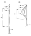
  • FIG. 1 is a schematic diagram of the said retractor which shows the state which accommodated the expansion body in the rigid perforated pipe, (b) is the exclusion of the expansion body.
  • FIG. 6 is a schematic diagram of the retractor showing a state in which the development body is extended from the perforated pipe in order to perform a cocoon-shaped development in the section, and (c) is a retraction part of the development body extended from the perforation pipe.
  • FIG. 1 It is a schematic diagram of the said retractor which shows the state which expand
  • the wire has a substantially circular cross section, a fixed wire having a substantially similar cross sectional shape is arranged in a part of the periphery of the movable wire, and is a cross-sectional view of an unexpanded exclusion portion, (b) being movable It is sectional drawing of the exclusion part which has the cross section which the wire has the shape which combined the circular arc and the string, and is not expand
  • FIG. 4 is a cross-sectional view of an extruding part that has a cross section with a convex portion in part and is not expanded, and (d) is a cross section of the movable wire having a substantially circular cross section around the movable wire.
  • Some of the fixed wires have substantially the same cross-sectional shape Is location, and a cross-sectional view of the retraction portion that is not expanded, the number of fixed wire disposed around the movable wire is cross-sectional view of the retraction portion of the case greater than the (a).
  • FIG. 1 A distal end part of a retractor of the present invention showing a deployment object extended from a perforated pipe and cocoon shape was developed FIG.
  • FIG. 1 A distal end part of a retractor of the present invention showing a deployment object extended from a perforated pipe and cocoon shape was developed FIG.
  • FIG. 1 A distal end part of a retractor of the present invention showing a deployment object extended from a perforated pipe and cocoon shape was developed FIG.
  • the retractor of this invention it is a figure which represents typically the example of the distal end front-end
  • FIG. 1 is a 1st grip part, a 2nd grip part, and a 3rd grip part when a deployment body is accommodated in the perforated pipe.
  • B is a diagram showing that the deployable body is extended from the perforated tube, and the first grip portion and the second grip portion, and the second grip portion and the third portion are separated.
  • FIG. 6C is a diagram showing a state in which the grip portions are in contact with each other
  • FIG. 8C is a diagram illustrating a state in which a deployable body is extended from the perforated pipe and the first grip, the second grip portion, and the third grip portion are separated from each other. It is a figure which shows being in the state performed. It is a figure showing the other example of the retractor of this invention, Comprising: It is a schematic diagram of the said retractor provided with a deployment body in the distal end of the long axis tube which has flexibility.
  • FIG. 1 is a diagram schematically illustrating an example of a retractor according to the present invention, and is a perspective view of the retractor showing a state where a deployable body is unfolded.
  • the retractor 100 of the present invention includes a deployment body 120, a rigid or rigid perforated pipe 110 that is an example of a storage pipe that can accommodate and extend the deployment body 120, and the proximal ends of the perforation pipe 110 and the deployment body 120, respectively. And a connected grip 160.
  • FIG. 2 is a side view of the retractor 100 of the present invention shown in FIG.
  • the retractor 100 of the present invention has the unfolded body completely accommodated in the perforated pipe 110 immediately before use, for example.
  • the proximal end of the perforated tube 110 is connected to the first grip portion 162 of the grip 160.
  • the term “retractor” refers to a medical device for excluding, opening, pulling, or raising an object (for example, an organ) or an object that obstructs the visual field in the medical field.
  • an object for example, an organ
  • an object that obstructs the visual field in the medical field for example, it includes a trocar and a mantle tube, and the operations of retraction, opening / retraction, traction, or elevation may be collectively referred to as “retraction” or “retract”.
  • the term “exclusion” may include not only an exclusion operation but also an operation of opening, pulling, or raising (that is, meaning retraction).
  • the retractor has, for example, an exclusion portion as described later, and is required to be deformable to a certain size after being inserted into the body.
  • distal refers to a position remote from the person operating the retractor
  • proximal refers to the person operating the retractor compared to “distal”. A close position.
  • distal end refers to the end furthest from (ie, distal to) the person operating the retractor of the present invention
  • proximal end Represents the end closest (ie, proximal) to the operator.
  • the perforated tube 110 is composed of, for example, a straight tube cut so that the distal end side has a sharp pointed shape.
  • the angle of the distal end tip of the piercing tube 110 is not particularly limited, but is processed to an angle (for example, 20 ° to 50 °) that facilitates piercing into the body.
  • the outer diameter of the perforated tube 110 is preferably 1.7 mm to 3.5 mm, and more preferably 2.2 mm to 3 mm.
  • the inner diameter of the perforated pipe 100 can be selected from the range of preferably 1.5 mm to 3 mm, more preferably 1.6 mm to 2.2 mm, with respect to the outer diameter.
  • the shape of the distal end tip portion of the perforated tube 110 is not necessarily limited to the above, and may have any shape that can be employed for a mantle tube or a trocar in the medical field, for example.
  • Such a perforated tube 110 is preferably made of a rigid material, for example, a metal such as stainless steel, tantalum, cobalt alloy, or nitinol (nickel-titanium alloy).
  • a metal such as stainless steel, tantalum, cobalt alloy, or nitinol (nickel-titanium alloy).
  • stainless steel examples include SUS304, SUS316, and SUS316L.
  • the retractor 100 according to the present invention also uses a perforated pipe 110 made of such a rigid material as a storage pipe, so that the desired position (for example, without concern about bending, bending, bending, etc. of the perforated pipe) can be obtained. Abdominal cavity). Furthermore, since the perforated pipe 110 is rigid, sufficient strength can be maintained even when a cocoon shape is developed and retracted at the exclusion portion described later.
  • the grip 160 is divided into the first grip 162 part, the second grip part 164 and the third grip part 166 in order from the distal end side.
  • the kind of material which comprises the grip 160 is not specifically limited.
  • the grip 160 is made of, for example, a resin such as an ABS resin, a polycarbonate resin, an acrylic resin, a metal such as stainless steel or aluminum, and a combination thereof.
  • FIG. 2B is a diagram schematically showing an example of the retractor 100 of the present invention.
  • the development body from the perforated pipe 110 is shown.
  • It is a schematic diagram of the said retractor 100 which shows the state which extended 120.
  • FIG. 1 is a diagram schematically showing an example of the retractor 100 of the present invention.
  • the term “cocoon shape” refers to a shape generated by the bending of a plurality of fixing wires, which will be described later, in the retraction portion of the deployment body, for example, a bowl shape or an elliptical sphere (such as a rugby ball). In order to distinguish from the “partial cocoon shape” described later, it may be referred to as a “complete cocoon shape”. Further, in the present specification, the term “partial cocoon shape” includes a shape obtained by partially cutting the cocoon shape along a direction parallel to the long axis of the complete cocoon shape.
  • the retractor 100 is accommodated in the perforated pipe 110 by pushing and pulling at least one of the second grip part 164 and the third grip part 166 of the grip 160 with respect to the first grip part 162.
  • the body 120 can be taken in and out.
  • the outer diameter is preferably 1.5 mm to 3 mm, more preferably 1.6 mm to 2 mm. It has a size that can slide freely in the perforated tube 110.
  • the total length of the retractor of the present invention is not necessarily limited.
  • the distance from the distal end to the proximal end of the piercing tube 110 (that is, from the distal end of the piercing tube 110 to the distal end of the first grip portion 162). ) Is preferably 100 mm to 300 mm.
  • FIG. 2C is a diagram schematically illustrating an example of the retractor 100 of the present invention, in which a partially cocoon-shaped structure is developed in the exclusion portion 122 of the deployment body 120 extending from the perforated pipe 110. It is a schematic diagram of the retractor 100 showing the state.
  • the retractor 100 of the present invention can deploy the deployment body 120 by further pushing and pulling at least one of the second grip portion 164 and the third grip portion 166 of the grip 160 with respect to the first grip portion 162.
  • the deployment body 120 includes an exclusion portion 122 and an introduction pipe 130 extending to the exclusion portion 122, and the exclusion portion 122 includes a movable wire 124 and at least three fixed wires disposed around the movable wire 124. 126.
  • the introduction tube 130 is tubular, and a movable wire 124 penetrates through the inside thereof.
  • the number of the fixed wires 126 arranged around the movable wire 124 is not particularly limited, but is, for example, 3 to 9, preferably 4 to 7.
  • Examples of materials constituting the introduction tube 130, the movable wire 124, and the fixed wire 126 include stainless steel such as SUS304, resin such as polyamide and PTFE, and stainless steel coated with resin.
  • the movable wire 124 has a sufficient linear strength that can withstand the load during the evacuation, for example, a linear strength of 1850 MPa or more, preferably 2100 MPa or more.
  • the movable wire 124, the fixed wire 126, and the introduction tube 130 that constitute the exclusion portion 122 have a smooth surface in order to prevent organ damage.
  • the coating material which has electrical insulation may be provided to these surfaces.
  • a coating material a material usually used for coating medical devices can be used. Examples thereof include a porous polytetrafluoroethylene (ePTFE) film, a silicone film, a polyurethane film, and a polyethylene terephthalate (Dacron (registered trademark)) film.
  • the thickness of the coating layer composed of the coating material is not particularly limited, but is, for example, 4 ⁇ m to 16 ⁇ m, preferably 8 ⁇ m to 12 ⁇ m.
  • the length of the exclusion part 122 accommodated in the perforated pipe 110 (not deployed) varies depending on the size of the retractor to be designed and is not necessarily limited.
  • the length of the exclusion portion accommodated in the perforated tube 110 is, for example, 40 mm to 120 mm, preferably 50 mm to 80 mm.
  • the size of the outer diameter of the exclusion portion 122 accommodated in the perforated pipe 110 is, for example, 1.5 mm to 3 mm, preferably 1.6 mm to 2 mm.
  • the length when the exclusion portion 122 is most deployed and the maximum diameter of the partial cocoon shape formed by deploying the fixing wire 126 of the exclusion portion 122 (the cut portion of the partial cocoon shape is supplemented to form a complete cocoon shape)
  • the maximum diameter in the case of assuming that it has, etc., is not necessarily limited because it varies depending on the size of the retractor to be designed.
  • the length of the exclusion portion is, for example, 35 mm to 80 mm, preferably 45 mm to 65 mm.
  • the maximum diameter of the partial cocoon shape is, for example, 20 mm to 80 mm, preferably 35 mm to 60 mm.
  • FIG. 3 is a diagram schematically showing an example of the deployable body 120 constituting the retractor of the present invention.
  • the deployment body 120 has a distal end of the movable wire 124 and a distal end of the fixed wire 126 with a cap 132 disposed at the tip of the distal end of the exclusion portion 122. The ends are joined. On the other hand, the proximal ends of the fixed wires 126 are also fixed to the introduction tube 130, and the movable wire 124 passes through the introduction tube 130.
  • the fixation wire 126 remains straight. Thereby, the deployment body 120 becomes the most deflated shape in the axial direction of the perforated tube 110 and can be freely slid within the perforated tube 110.
  • a partially cocoon-shaped structure can be developed by a plurality of fixed wires 126 by extending the deployment body 120 from the perforated tube 110.
  • the distal ends of the movable wire 124 and the fixed wire 126 remain fixed to the cap 132, whereas the closer the cap 132 and the distal end of the introduction tube 130 approach, the fixed wire
  • Each of 126 is deflected in a direction away from the axis of the movable wire 124 (radial direction), and a partial cocoon-shaped structure including a plurality of fixed wires 126 can be constructed as the exclusion portion 122.
  • the partial cocoon-shaped structure can exclude the inner wall of the luminal organ or the organ in the body cavity to form a predetermined space in the lumen or the body cavity.
  • FIG. 4 is a diagram schematically illustrating examples of cross-sectional views (cross-sectional views of the movable wire 124 and the fixed wire 126) of the exclusion portion 122 in a direction orthogonal to the long axis of the deployable body 120 constituting the retractor 100 of the present invention. It is. 4A to 4C are cross-sectional views of the exclusion portion when the exclusion portion 122 is not deployed (that is, in the accommodated state).
  • the movable wire 124 may have a substantially circular cross section as shown in FIG. 4 (a), and a combined shape of an arc and a string as shown in FIG. 4), or a shape having a convex portion on a part of the chord among shapes obtained by combining arcs and chords as shown in FIG. 4C. It may be. As other cross-sectional shapes, you may have shapes, such as a regular polygon (a square, a regular hexagon, a regular octagon, etc.). A plurality of fixed wires 126 having substantially the same cross-sectional shape are arranged around the movable wire 124 except for a part thereof.
  • each fixed wire 126 is in contact with the movable wire 124 preferably has a shape that substantially matches the outer diameter of the movable wire 124. This is because an unnecessary space is not formed between the fixed wire 126 and the movable wire 124, and the entire volume of the exclusion portion 122 at the time of accommodation can be made as small as possible.
  • the cross section of the fixed wire 126 is, for example, a portion in which a part of the cross section substantially coincides with a part of the outer periphery of the cross section of the movable wire 124 as shown in FIGS. It has an annular shape. That is, the cross section of the fixed wire 126 may have a shape obtained by cutting out a part of the arc as it is from the circular ring as shown in FIG. 5A, as shown in FIG. For example, in order to reduce the damage of surrounding tissue due to the difference in exclusion, the partial annular shape shown in the above (a) may have a dull shape with rounded corners, and As shown in FIG.
  • each cross-section is crescent. It may have a certain shape.
  • the cross-sections of the plurality of fixed wires 126 are preferably the same as each other in order to perform uniform development.
  • the fixed wire 126 is easily developed and sufficient strength is provided to each of the wires 124 and 126.
  • the length ratio (A / B) satisfies, for example, 2 to 10, preferably 3 to 7.
  • the A is 1.2 mm and the B is 0.25 mm (in this case A / B is 4.8).
  • the fixed wire 126 is arranged only in a part around the movable wire 124, and the wire is not arranged around the rest. Therefore, by changing the diameter, material, cross-sectional shape, and the like of the movable wire 124, when the deployable body 120 is opened, a bending force acts on the portion around the movable wire 124 where the fixed wire 126 is not disposed. Then, the movable wire 124 can construct a shape that is bent by itself along the axial direction of the perforated pipe 110 (more specifically, over the entire portion of the movable wire 124 corresponding to the exclusion portion 122). Yes (Fig. 6).
  • the exclusion portion 122 is bent with respect to the axial direction of the perforated tube 110 on the proximal side of the exclusion portion 122 (that is, near the distal end of the introduction tube 130).
  • Such bending of the movable wire 124 and bending of the exclusion portion 122 further increase the scale of retraction (substantial volume), and the operability of the retractor can be further enhanced.
  • Such a retractor in which the exclusion portion 122 can be bent with respect to the axial direction of the perforated pipe 110 is, for example, the cross-sectional shape of the movable wire and the arrangement of the fixed wire as shown in FIGS. Can be easily manufactured.
  • the bending angle ⁇ 0 of the exclusion portion 122 is, for example, 5 ° to 45 °, preferably 10 ° to 30 °.
  • Such adjustment of the bending angle ⁇ 0 of the exclusion portion 122 can be realized, for example, by selecting the movable wire 124 having lower strength than the fixed wire 126 or having elasticity. More specific examples: (1) Use a stranded wire for the movable wire 124; (2) The cross section of the movable wire 124 is processed into an irregular shape as shown in, for example, FIG.
  • the cross-sectional area of the movable wire 124 is set smaller than the cross-sectional area of the fixed wire 126 (a thin wire is used for the movable wire 124); and (4) a low Young such as a Ni—Ti alloy is used for the movable wire 124. Rate material; (5) Use a wire in which the movable wire 124 is bent in advance in the exclusion portion 122. (6) A plurality of combinations of the above (1) to (5); Is mentioned.
  • one deployment angle ⁇ 2 is larger than the remaining deployment angle ⁇ 1 among the deployment angles formed between two adjacent fixed wires in the exclusion portion when the deployment body is deployed.
  • the number and arrangement of the fixed wires 126 are selected with respect to the movable wire 124 so that the development angle ⁇ 2 has a predetermined angle.
  • deployment angle used in the present specification means that when the retractor when the retractor deployment body is deployed is viewed from the distal end side of the retractor, one fixed wire and its adjacent It refers to the angle formed with the fixed wire.
  • such a deployment angle ⁇ 2 is 90 ° to 240 °, preferably 120 ° to 240 °, more preferably 120 ° to 180 °.
  • the remaining development angle ( ⁇ 1) as long as all of the remaining development angles ⁇ 1 are smaller than the development angle ⁇ 2, these angles may be set to be substantially the same or different from each other. It may be set.
  • FIG. 7 is a diagram schematically showing an example of the distal end tip portion of the retractor when the deployable body 120 is extended from the perforated tube 110 and deployed in the retractor 100 of the present invention.
  • the fixing wire 124 of the exclusion portion 122 that constitutes the retractor of the present invention is composed of five fixing wires.
  • one deployment angle ⁇ 2 is approximately 180 °
  • the remaining deployment angle ⁇ 1 is approximately 45 °.
  • the fixing wire 124 of the exclusion portion 122 that constitutes the retractor of the present invention is composed of six fixing wires.
  • one deployment angle ⁇ 2 is approximately 135 °
  • the remaining deployment angle ⁇ 1 is approximately 45 °.
  • the deployment angle ⁇ 2 and the other deployment angle ⁇ 1 satisfy the above relationship, the workability is improved between the two fixed wires having the deployment angle ⁇ 2 in the exclusion portion 122. A region of retraction can be formed.
  • the extension of the deployment body from the storage tube, the storage of the deployment body in the storage tube, and the deployment or storage of the exclusion portion in the deployment body are performed by a grip provided on the proximal end side of the retractor. Be controlled.
  • FIG. 8 is a schematic cross-sectional view of the retractor showing an example of the retractor 100 of the present invention.
  • the proximal end of the perforated pipe (accommodating pipe) 110 is connected to the first grip 162, and the proximal end of the introduction pipe 130 of the exclusion section 122 is The proximal end of the movable wire 124 of the exclusion portion 122 is connected to the third grip portion 166.
  • the retractor 100 of the present invention when the deployable body 120 is accommodated in the perforated pipe 110, as shown in FIG. The grip part 164 and the third grip part 166 are isolated. In this state, the retractor 100 of the present invention is inserted into the inner wall of the hollow organ or the organ in the body cavity by drilling from the distal end of the perforated tube 110 through the incision or directly.
  • the second grip portion 164 and the third grip portion 166 are pushed into the first grip 162 toward the distal end side, that is, the first grip portion 162 side.
  • the introduction tube 130 and the movable wire 124 connected to the second grip portion 164 and the third grip portion 166, respectively, are pushed out to the distal side, and the deployable body 120 is extended from the perforated tube 110.
  • the fixed wire 126 is expanded from the exclusion portion 122 in the expanded body 120.
  • the deployment of the fixed wire 126 from the exclusion portion 122 is, for example, the length of each of the introduction tube 130 and the movable wire 124 with respect to the length of the perforated tube 110, and when the deployable body 120 extends from the perforated tube 110.
  • the second grip part 164 and the third grip part 166 with respect to the first grip part 162 for example, the following is performed.
  • the proximal end of the first grip portion 162 is in contact with the distal end of the second grip portion 164 in a state where the deployment body 120 extends from the perforated tube 110.
  • the first grip portion 162 and the second grip portion 164 are pulled out, only the third grip portion 166 is pulled out to the proximal side (hand side) with respect to the first grip portion 162 and the second grip portion 164.
  • Only the movable wire 124 slides proximally while the introduction tube 130 is fixed with respect to 110.
  • the distal end of the fixed wire 126 joined to the movable wire 124 at the portion of the cap 132 also slides proximally.
  • the fixing wire 126 since the proximal end of the fixing wire 126 is joined to the distal end of the introduction tube 130 and is in a fixed state, the fixing wire 126 is curved outward. As a result, a plurality of fixed wires 126 are deployed in the exclusion portion 122, and a partial cocoon shape is developed. And by the expression of this partial cocoon shape, the exclusion in the inserted luminal organ or body cavity is achieved.
  • the partial cocoon developed in the exclusion portion 122 by changing the length of the third grip portion 164 and / or the second grip portion 124 to be pulled out or pushed out.
  • the size of the shape structure can be freely changed.
  • retractor of this invention is not necessarily limited to the trocar or outer tube provided with the above perforated pipes.
  • FIG. 9 is a schematic diagram showing another example of the retractor of the present invention.
  • the retractor 200 of the present invention includes a deployment body 120, a flexible long-axis tube 210 that is another example of a storage tube that can accommodate and extend the deployment body 120, a long-axis tube 210, and A grip 260 is connected to each proximal end of the deployment body 120.
  • the retractor 200 shown in FIG. 9 functions as a so-called snake retractor because the long-axis tube 210 has flexibility, and can freely pass through, for example, a lumen. Except for using the long-axis tube 210 instead of the perforated tube, the specific structures of the deployment body 120 and the grip 260 are the same as those of the retractor 100 of the present invention.
  • the retractor of the present invention is used for excretion in various operations in luminal organs such as stomach, small intestine, large intestine, and vagina, and other organs such as liver, pancreas, kidney, gallbladder, spleen, uterus, and lung. .
  • a retractor capable of freely excluding an organ can be provided. Furthermore, according to the present invention, the visual field and the operation space can be secured without injecting gas into the body cavity, which is also useful in that, for example, a gasless operation is possible.

Abstract

The purpose of the present invention is to provide a retractor with which it is possible to reduce the emotional and physical load on a patient and a surgeon by reducing the generation of sparks in an operative field caused by undeliberate contact between an expanded retractor and another surgical device (such as an electric surgical knife). The present invention is a retractor for displacing an organ within the body cavity or the inner wall of a hollow organ, the retractor being provided with: a housing tube; an expansion body which can be housed into and extend from the housing tube; and a grip connected to the proximal ends of the housing tube and the expansion body. The expansion body is provided with: a displacing part configured from a movable wire and multiple fixed wires disposed in the periphery of the moveable wire; and an introduction tube which is disposed along the displacing part and through which the movable wire penetrates. Moreover, when the expansion body is expanded, the displacement part is designed so that, from among the expansion angles formed by two adjacent fixed wires, one expansion angle (θ2) becomes larger than the other expansion angle (θ1).

Description

リトラクタRetractor
 本発明は、リトラクタに関し、より詳細には、管腔臓器の内壁または体腔内の臓器を圧排するために使用される3次元方向に展開可能なリトラクタに関する。 The present invention relates to a retractor, and more particularly to a retractor that can be deployed in a three-dimensional direction and is used to exclude an inner wall of a luminal organ or an organ in the body cavity.
 従来の開腹手術では、手術の妨げとなる臓器を手で開排することができるが、このような内視鏡下手術では、臓器の開排は容易ではなく、手術に最適な視野を確保するのが難しいことが知られている。例えば、視野と操作空間とを確保するため、体腔内に気体を注入する方法があるが、この方法は全身麻酔を必要とし、低侵襲性とはいえない。 In conventional laparotomy, organs that hinder the operation can be removed manually, but in such endoscopic surgery, opening of the organ is not easy, ensuring an optimal field of view for the operation. It is known that it is difficult. For example, there is a method of injecting a gas into a body cavity in order to secure a visual field and an operation space. However, this method requires general anesthesia and is not minimally invasive.
 視野の問題などを緩和し、内視鏡治療を容易にするために、治療対象臓器や治療中の視野の妨げとなる臓器などを圧排あるいは牽引するリトラクタと呼ばれる器具が開発されている。リトラクタには、基本的な機能として、これを体内へ挿入する際、挿入通路となるトロッカー(外套管)または小切開創のような小さな開口通路より器具が挿通できることが求められている。したがって、少なくとも挿入時は細径であり(例えば、トロッカーの場合10mm以下、小切開創の場合20mm以下が望ましい)かつ棒状の形態であることが必要であり、一方、体腔内挿入後は、対象物を幅広く安全に圧排するために、圧排部がある程度大きな面積を有する形状に変形可能であることが要求される。 In order to alleviate visual field problems and facilitate endoscopic treatment, an apparatus called a retractor has been developed that excludes or pulls the organ to be treated or an organ that interferes with the visual field during treatment. As a basic function, the retractor is required to allow a device to be inserted through a small opening passage such as a trocar (outer tube) or a small incision serving as an insertion passage when the retractor is inserted into the body. Therefore, it is necessary to have a small diameter at least at the time of insertion (for example, 10 mm or less for a trocar, and preferably 20 mm or less for a small incision) and a rod-like form. In order to exclude objects widely and safely, it is required that the excluding portion be deformable into a shape having a certain large area.
 上述の相反する要求に応じて、種々に工夫されたリトラクタが提案あるいは市販されている。例えば、圧排部が扇状に拡開するものがある(例えば、特許文献1)。これは、トロッカーの腹腔への挿入時には、扇状圧排部が畳まれて棒状管の内部に収容されており、体腔内で棒状管より押し出されて扇状に広がるものである。扇状圧排部を任意の大きさまで手元操作により拡げる構造のものや、圧排部と基部との角度が可変するものなどがあり、比較的幅広く臓器を圧排できる利点があることから肝臓や腸を圧排するのに好適となっている。なお、形状は扇型に限らず、菱形などの種々の形状のものが多数提案されている。 In response to the above conflicting requirements, various devised retractors have been proposed or marketed. For example, there is one in which the exclusion portion expands in a fan shape (for example, Patent Document 1). When the trocar is inserted into the abdominal cavity, the fan-shaped exclusion portion is folded and accommodated inside the rod-shaped tube, and is pushed out from the rod-shaped tube within the body cavity and spreads in a fan shape. There are structures that can expand the fan-shaped exclusion part to an arbitrary size by hand operation, and those that can change the angle between the exclusion part and the base, etc. It is suitable for. Note that the shape is not limited to a fan shape, and many shapes having various shapes such as rhombus have been proposed.
 特に、臓器内をより効果的に圧排するとともに操作性に優れたリトラクタの開発が所望されている。 In particular, there is a demand for the development of a retractor that can more effectively evacuate an organ and has excellent operability.
 さらに、そのような操作性のうち、リトラクタを用いた各種手術が行われる際、展開したリトラクタとその他の手術デバイス(例えば、電子メス)とが不用意に接触し、術野でスパークを生じることが懸念される。このため、術者には当該接触を防ぐためのより慎重な作業が必要とされている。こうした作業は術者にとって長時間にわたる極度の緊張を強いる負担であり、長時間の手術は、患者にとっても肉体的負担を増幅させるおそれがある。 Furthermore, among various types of operability, when various types of surgery using the retractor are performed, the retracted retractor and other surgical devices (for example, electronic scalpels) may inadvertently contact and cause sparks in the surgical field. Is concerned. For this reason, the surgeon needs more careful work to prevent the contact. Such work is a burden that imposes extreme tension over a long period of time for the surgeon, and a long-time operation may increase the physical burden for the patient.
特開平6-154152号公報JP-A-6-154152
 本発明は上記問題の解決を課題とするものであり、その目的とするところは、術野を広く確保し、展開したリトラクタとその他の手術デバイス(例えば、電子メス)との不用意な接触による術野でのスパーク発生を低減し、術者および患者の精神的かつ肉体的負担を軽減し得るリトラクタを提供することにある。 The present invention has an object to solve the above-mentioned problems, and the object of the present invention is to ensure a wide surgical field and to careless contact between the deployed retractor and other surgical devices (for example, an electronic knife). An object of the present invention is to provide a retractor that can reduce the occurrence of sparks in the operative field and reduce the mental and physical burden on the operator and the patient.
 本発明は、管腔臓器の内壁または体腔内の臓器を圧排するためのリトラクタであって、
 収納管と、
 該収納管に対し、収容かつ延出可能な展開体と、
 該収納管および該展開体のそれぞれ近位端と接続されたグリップと
を備え、
ここで、
 該展開体が、
 可動ワイヤおよび該可動ワイヤの周囲に配置された少なくとも3本の固定ワイヤから構成される圧排部;および
 該圧排部に延設されており、かつ該可動ワイヤが貫通する、導入管;
を備え、そして
 該圧排部において該可動ワイヤの遠位端と該固定ワイヤの遠位端とが接合されており、
 該展開体が展開された際の該圧排部における、隣接する2つの該固定ワイヤの間で形成される展開角度のうち、1つの展開角度θ2が残りの展開角度θ1よりも大きく、かつ
 該展開角度θ2が90°から240°である、リトラクタである。
The present invention is a retractor for excluding an inner wall of a hollow organ or an organ in a body cavity,
A storage tube;
A deployable body that can be housed and extended with respect to the housing tube;
A grip connected to the proximal end of each of the storage tube and the deployment body,
here,
The deployment body is
An excluding portion composed of a movable wire and at least three fixed wires disposed around the movable wire; and an introduction tube extending through the excluding portion and through which the movable wire passes;
And the distal end of the movable wire and the distal end of the fixed wire are joined at the exclusion portion,
One deployment angle θ2 is larger than the remaining deployment angle θ1 among the deployment angles formed between the two adjacent fixed wires in the exclusion portion when the deployment body is deployed, and the deployment The retractor having an angle θ2 of 90 ° to 240 °.
 1つの実施形態では、上記収納管は剛直な穿孔管である。 In one embodiment, the storage tube is a rigid perforated tube.
 さらなる実施形態では、上記展開体が展開された際に、上記圧排部は上記穿孔管の軸方向に対して屈曲する。 In a further embodiment, when the deployment body is deployed, the exclusion portion is bent with respect to the axial direction of the perforated pipe.
 1つの実施形態では、上記グリップは、遠位側から第1グリップ部、第2グリップ部および第3グリップ部を備え、
ここで、
 上記収納管の近位端が該第1グリップ部に接続されており、
 上記圧排部の上記導入管の近位端が該第2グリップ部に接続されており、そして
 該圧排部の上記可動ワイヤの近位端が該第3グリップ部に接続されている。
In one embodiment, the grip includes a first grip portion, a second grip portion, and a third grip portion from the distal side,
here,
A proximal end of the storage tube is connected to the first grip portion;
The proximal end of the introduction tube of the exclusion portion is connected to the second grip portion, and the proximal end of the movable wire of the exclusion portion is connected to the third grip portion.
 1つの実施形態では、上記可動ワイヤの断面は略円形を有する。 In one embodiment, the cross section of the movable wire has a substantially circular shape.
 1つの実施形態では、上記第1グリップ部に対して、上記第2グリップ部および上記第3グリップ部の少なくとも1つを押し引きすることにより、上記圧排部における上記固定ワイヤの湾曲を制御可能である。 In one embodiment, it is possible to control the bending of the fixing wire in the exclusion portion by pushing and pulling at least one of the second grip portion and the third grip portion with respect to the first grip portion. is there.
 1つの実施形態では、上記収納管は可撓性を有する長軸管である。 In one embodiment, the storage tube is a long-axis tube having flexibility.
 本発明によれば、自在に臓器を圧排することが可能なリトラクタを提供することができる。本発明のリトラクタは、展開体を展開した際、圧排部の1つの固定ワイヤと隣接する他の固定ワイヤとの間に形成される展開角度θ2が他の展開角度θ1よりも大きいため、展開角度θ2によって構成される展開空間が、展開角度θ1によって構成される展開空間よりも広くなり、術者の作業性が向上したより広範な術野を得ることができる。その結果、電子メスなどのエネルギー素子を含む手術デバイスとの併用の際、当該デバイスが固定ワイヤに誤って接触することによる所望でないスパークが生じる確率を著しく低減させることができる。 According to the present invention, a retractor capable of freely excluding an organ can be provided. In the retractor of the present invention, when the deployment body is deployed, the deployment angle θ2 formed between one fixed wire of the exclusion portion and another adjacent fixed wire is larger than the other deployment angle θ1, so the deployment angle The deployment space constituted by θ2 becomes wider than the deployment space constituted by the deployment angle θ1, and a wider surgical field with improved operator workability can be obtained. As a result, when used in combination with a surgical device including an energy element such as an electronic scalpel, the probability of undesired sparks due to erroneous contact of the device with the fixation wire can be significantly reduced.
本発明のリトラクタの一例を模式的に表す図であって、展開体が展開した状態を示す当該リトラクタの斜視図である。It is a figure which represents typically an example of the retractor of this invention, Comprising: It is a perspective view of the said retractor which shows the state which the expansion body expand | deployed. 図1に示す本発明のリトラクタを表す図であって、(a)は、剛直な穿孔管内に展開体を収容した状態を示す当該リトラクタの模式図であり、(b)は、展開体の圧排部においてコクーン形状の展開を行うために、穿孔管から当該展開体を延出した状態を示す当該リトラクタの模式図であり、そして(c)は、穿孔管から延出した展開体の圧排部においてコクーン形状の構造物を展開した状態を示す当該リトラクタの模式図である。It is a figure showing the retractor of this invention shown in FIG. 1, Comprising: (a) is a schematic diagram of the said retractor which shows the state which accommodated the expansion body in the rigid perforated pipe, (b) is the exclusion of the expansion body. FIG. 6 is a schematic diagram of the retractor showing a state in which the development body is extended from the perforated pipe in order to perform a cocoon-shaped development in the section, and (c) is a retraction part of the development body extended from the perforation pipe. It is a schematic diagram of the said retractor which shows the state which expand | deployed the cocoon-shaped structure. 本発明のリトラクタを構成する展開体の一例を模式的に表す図であって、(a)は穿孔管内に展開体が収容された状態の表す本発明のリトラクタの遠位端部分の長軸方向における断面図であり、そして(b)は穿孔管から延出され、かつコクーン形状が展開された展開体を表す本発明のリトラクタの遠位端部分の一部切欠断面図である。It is a figure which represents typically an example of the expansion body which comprises the retractor of this invention, Comprising: (a) The long-axis direction of the distal end part of the retractor of this invention which represents the state in which the expansion body was accommodated in the perforated pipe And (b) is a partially cutaway cross-sectional view of the distal end portion of the retractor of the present invention representing a deployment body extending from the piercing tube and having a cocoon shape deployed. 本発明のリトラクタを構成する展開体の長軸に直交する方向における圧排部の断面図(可動ワイヤおよび固定ワイヤの断面図)の例をそれぞれ模式的に表す図であって、(a)は可動ワイヤが略円形の断面を有し、当該可動ワイヤの周囲の一部に略同様の断面形状を有する固定ワイヤが配置され、かつ展開されていない圧排部の断面図であり、(b)は可動ワイヤが円弧と弦とを組み合わせた形状からなる断面を有し、かつ展開されていない圧排部の断面図であり、(c)は可動ワイヤが円弧と弦とを組合せた形状のうち当該弦の一部に凸部を有する形状の断面を有し、かつ展開されていない圧排部の断面図であり、そして(d)は、可動ワイヤが略円形の断面を有し、当該可動ワイヤの周囲の一部に略同様の断面形状を有する固定ワイヤが配置され、かつ展開されていない圧排部の断面図であって、可動ワイヤの周囲に配置された固定ワイヤの数が上記(a)よりも多い場合の圧排部の断面図ある。It is a figure showing typically each example of a sectional view (sectional view of a movable wire and a fixed wire) of an exclusion part in a direction perpendicular to a major axis of a deployment object which constitutes a retractor of the present invention, and (a) is movable. The wire has a substantially circular cross section, a fixed wire having a substantially similar cross sectional shape is arranged in a part of the periphery of the movable wire, and is a cross-sectional view of an unexpanded exclusion portion, (b) being movable It is sectional drawing of the exclusion part which has the cross section which the wire has the shape which combined the circular arc and the string, and is not expand | deployed, (c) is the direction of the said string among the shapes which the movable wire combined the circular arc and the string FIG. 4 is a cross-sectional view of an extruding part that has a cross section with a convex portion in part and is not expanded, and (d) is a cross section of the movable wire having a substantially circular cross section around the movable wire. Some of the fixed wires have substantially the same cross-sectional shape Is location, and a cross-sectional view of the retraction portion that is not expanded, the number of fixed wire disposed around the movable wire is cross-sectional view of the retraction portion of the case greater than the (a). 本発明を構成する展開体の固定ワイヤの断面の例を模式的に表す当該ワイヤの断面図である。It is sectional drawing of the said wire | line showing typically the example of the cross section of the fixed wire of the expansion | deployment body which comprises this invention. 本発明のリトラクタを構成する展開体の他の例を模式的に表す図であって、穿孔管から延出され、かつコクーン形状が展開された展開体を表す本発明のリトラクタの遠位端部分の一部切欠断面図である。It is a figure showing typically other examples of a deployment object which constitutes a retractor of the present invention, Comprising: A distal end part of a retractor of the present invention showing a deployment object extended from a perforated pipe and cocoon shape was developed FIG. 本発明のリトラクタにおいて、穿孔管から展開体を延出し、かつ展開した際の、当該リトラクタの遠位端先端部の例を模式的に表す図であって、(a)は5本の固定ワイヤで構成され、展開角度θ1が略45°でありかつ展開角度θ2が略180°である場合の当該遠位端先端部の一例を表す図であり、そして(b)は6本の固定ワイヤで構成され、展開角度θ1が略45°でありかつ展開角度θ2が略135°である場合の当該遠位端先端部の一例を表す図である。In the retractor of this invention, it is a figure which represents typically the example of the distal end front-end | tip part of the said retractor at the time of extending | deploying and deploying a deployment body from a piercing pipe | tube, Comprising: (a) is five fixed wires. Is a diagram showing an example of the distal end tip portion when the deployment angle θ1 is about 45 ° and the deployment angle θ2 is about 180 °, and (b) shows six fixed wires. It is a figure showing an example of the said distal end front-end | tip part when comprised and deployment angle | corner (theta) 1 is about 45 degrees and expansion | deployment angle (theta) 2 is about 135 degrees. 本発明のリトラクタの一例を示す当該リトラクタの模式断面図であって、(a)は、穿孔管内に展開体が収容された際の、第1グリップ部と第2グリップ部および第3グリップ部との間が隔離されている状態にあることを示す図であり、(b)は、穿孔管から展開体が延出され、第1グリップ部および第2グリップ部と、第2グリップ部および第3グリップ部とがそれぞれ接触している状態を示す図であり、そして(c)は、穿孔管から展開体が延出され、第1グリップと第2グリップ部および第3グリップ部との間が隔離されている状態にあることを示す図である。It is a schematic cross section of the said retractor which shows an example of the retractor of this invention, Comprising: (a) is a 1st grip part, a 2nd grip part, and a 3rd grip part when a deployment body is accommodated in the perforated pipe. (B) is a diagram showing that the deployable body is extended from the perforated tube, and the first grip portion and the second grip portion, and the second grip portion and the third portion are separated. FIG. 6C is a diagram showing a state in which the grip portions are in contact with each other, and FIG. 8C is a diagram illustrating a state in which a deployable body is extended from the perforated pipe and the first grip, the second grip portion, and the third grip portion are separated from each other. It is a figure which shows being in the state performed. 本発明のリトラクタの他の例を表す図であって、可撓性を有する長軸管の遠位端にて展開体を備える当該リトラクタの模式図である。It is a figure showing the other example of the retractor of this invention, Comprising: It is a schematic diagram of the said retractor provided with a deployment body in the distal end of the long axis tube which has flexibility.
 本発明を、図面を用いて詳述する。 The present invention will be described in detail with reference to the drawings.
 図1は、本発明のリトラクタの一例を模式的に表す図であって、展開体が展開した状態を示す当該リトラクタの斜視図である。 FIG. 1 is a diagram schematically illustrating an example of a retractor according to the present invention, and is a perspective view of the retractor showing a state where a deployable body is unfolded.
 本発明のリトラクタ100は、展開体120と、展開体120を収容かつ延出可能な収納管の一例である剛直あるいは硬質な穿孔管110と、穿孔管110および展開体120のそれぞれ近位端と接続されたグリップ160とを備える。 The retractor 100 of the present invention includes a deployment body 120, a rigid or rigid perforated pipe 110 that is an example of a storage pipe that can accommodate and extend the deployment body 120, and the proximal ends of the perforation pipe 110 and the deployment body 120, respectively. And a connected grip 160.
 図2は、図1に示す本発明のリトラクタ100の側面図である。図2の(a)に示すように、本発明のリトラクタ100は、例えば、使用直前においては、穿孔管110内に展開体が完全に収容されている。また、穿孔管110の近位端はグリップ160の第1グリップ部162と接続されている。 FIG. 2 is a side view of the retractor 100 of the present invention shown in FIG. As shown in FIG. 2A, the retractor 100 of the present invention has the unfolded body completely accommodated in the perforated pipe 110 immediately before use, for example. The proximal end of the perforated tube 110 is connected to the first grip portion 162 of the grip 160.
 ここで、本明細書中に用いられる用語「リトラクタ」とは、医療分野における対象物(例えば、臓器)あるいは視野を妨げるものを圧排、開排、牽引、または挙上するための医療器具をいい、例えば、トロッカーおよび外套管を包含し、圧排、開排、牽引、または挙上の操作をまとめて「リトラクション」または「リトラクト」という場合がある。なお、単に本明細書中において「圧排」という場合は、圧排の操作のみでなく、開排、牽引、または挙上する操作を包含する(すなわち、リトラクションを意味する)場合がある。リトラクタは、例えば、後述するように圧排部を有し、体内へ挿入後、圧排部がある程度の大きさに変形可能であることが要求される。 As used herein, the term “retractor” refers to a medical device for excluding, opening, pulling, or raising an object (for example, an organ) or an object that obstructs the visual field in the medical field. For example, it includes a trocar and a mantle tube, and the operations of retraction, opening / retraction, traction, or elevation may be collectively referred to as “retraction” or “retract”. In the present specification, the term “exclusion” may include not only an exclusion operation but also an operation of opening, pulling, or raising (that is, meaning retraction). The retractor has, for example, an exclusion portion as described later, and is required to be deformable to a certain size after being inserted into the body.
 さらに、本明細書に用いられる用語「遠位」とは、リトラクタを操作する者から遠い位置をいい、そして用語「近位」とは、「遠位」と比較してリトラクタを操作する者から近い位置をいう。このため、用語「遠位端」とは、本発明のリトラクタを操作する際に、操作する者から最も遠い(すなわち、遠位にある)端部を表し、用語「近位端」とは、当該操作する者から最も近い(すなわち、近位にある)端部を表す。 Further, as used herein, the term “distal” refers to a position remote from the person operating the retractor, and the term “proximal” refers to the person operating the retractor compared to “distal”. A close position. For this reason, the term “distal end” refers to the end furthest from (ie, distal to) the person operating the retractor of the present invention, and the term “proximal end” Represents the end closest (ie, proximal) to the operator.
 再び図2の(a)を参照すると、1つの実施形態では、穿孔管110は、例えば、遠位端側が鋭い尖った形状となるように切断されたストレートな管から構成されている。穿孔管110の遠位端先端部の角度は特に限定されないが、体内への穿孔が容易となる角度(例えば、20°~50°)に加工されている。穿孔管110の外径は、好ましくは1.7mm~3.5mmであり、より好ましくは2.2mm~3mmである。さらに、穿孔管100の内径は、上記外径に対し、好ましくは1.5mm~3mm、より好ましくは1.6mm~2.2mmの範囲から選択され得る。なお、本発明において穿孔管110の遠位端先端部の形状は、必ずしも上記に限定されず、例えば、医療分野における外套管またはトロッカーに採用され得る任意の形状を有していてもよい。 Referring again to FIG. 2 (a), in one embodiment, the perforated tube 110 is composed of, for example, a straight tube cut so that the distal end side has a sharp pointed shape. The angle of the distal end tip of the piercing tube 110 is not particularly limited, but is processed to an angle (for example, 20 ° to 50 °) that facilitates piercing into the body. The outer diameter of the perforated tube 110 is preferably 1.7 mm to 3.5 mm, and more preferably 2.2 mm to 3 mm. Further, the inner diameter of the perforated pipe 100 can be selected from the range of preferably 1.5 mm to 3 mm, more preferably 1.6 mm to 2.2 mm, with respect to the outer diameter. In the present invention, the shape of the distal end tip portion of the perforated tube 110 is not necessarily limited to the above, and may have any shape that can be employed for a mantle tube or a trocar in the medical field, for example.
 このような穿孔管110は、剛直な材料、例えば、ステンレス、タンタル、コバルト合金、ナイチノール(ニッケル-チタン合金)などの金属から構成されていることが好ましい。ステンレスとしては、例えば、SUS304、SUS316、SUS316Lが挙げられる。本発明のリトラクタ100はまた、収納管としてこのような剛直な材料で構成される穿孔管110を用いることにより、当該穿孔管の撓み、曲がり、折れなどを懸念することなく、所望の位置(例えば、腹腔)に確実に穿孔することができる。さらに、当該穿孔管110が剛直であることにより、後述する圧排部でのコクーン形状の展開やリトラクトの際にも充分な強度を保持することができる。 Such a perforated tube 110 is preferably made of a rigid material, for example, a metal such as stainless steel, tantalum, cobalt alloy, or nitinol (nickel-titanium alloy). Examples of stainless steel include SUS304, SUS316, and SUS316L. The retractor 100 according to the present invention also uses a perforated pipe 110 made of such a rigid material as a storage pipe, so that the desired position (for example, without concern about bending, bending, bending, etc. of the perforated pipe) can be obtained. Abdominal cavity). Furthermore, since the perforated pipe 110 is rigid, sufficient strength can be maintained even when a cocoon shape is developed and retracted at the exclusion portion described later.
 グリップ160は、遠位端側から順に上記第1グリップ162部、第2グリップ部164および第3グリップ部166の3つに分割されている。グリップ160を構成する材料の種類は特に限定されない。グリップ160は、例えば、ABS樹脂、ポリカードネート樹脂、アクリル樹脂などの樹脂や、ステンレス鋼、アルミニウムなどの金属およびこれらの組合せから構成されている。 The grip 160 is divided into the first grip 162 part, the second grip part 164 and the third grip part 166 in order from the distal end side. The kind of material which comprises the grip 160 is not specifically limited. The grip 160 is made of, for example, a resin such as an ABS resin, a polycarbonate resin, an acrylic resin, a metal such as stainless steel or aluminum, and a combination thereof.
 図2の(b)は、本発明のリトラクタ100の一例を模式的に表した図であって、展開体の圧排部において部分的コクーン形状の展開を行うために、穿孔管110から当該展開体120を延出した状態を示す当該リトラクタ100の模式図である。 FIG. 2B is a diagram schematically showing an example of the retractor 100 of the present invention. In order to perform a partial cocoon-shaped development in the extruding part of the development body, the development body from the perforated pipe 110 is shown. It is a schematic diagram of the said retractor 100 which shows the state which extended 120. FIG.
 なお、本明細書において、用語「コクーン形状」とは、展開体の圧排部において、後述する複数の固定ワイヤの湾曲によって生じた形状であって、例えば、繭状または楕円球体(ラグビーボール等)状の形状を包含して言い、後述する「部分的コクーン形状」と区別するために「完全コクーン形状」と言うこともある。さらに、本明細書において、用語「部分的コクーン形状」とは、上記完全コクーン形状の長軸と平行な方向に沿って、当該コクーン形状の一部が切除されたものを包含して言う。 In the present specification, the term “cocoon shape” refers to a shape generated by the bending of a plurality of fixing wires, which will be described later, in the retraction portion of the deployment body, for example, a bowl shape or an elliptical sphere (such as a rugby ball). In order to distinguish from the “partial cocoon shape” described later, it may be referred to as a “complete cocoon shape”. Further, in the present specification, the term “partial cocoon shape” includes a shape obtained by partially cutting the cocoon shape along a direction parallel to the long axis of the complete cocoon shape.
 本発明のリトラクタ100は、グリップ160における第2グリップ部164および第3グリップ部166の少なくとも1つを第1グリップ部162に対して押し引きすることにより、穿孔管110内に収容されている展開体120を出し入れすることができる。展開体120は、穿孔管110内に収容されている際(後述するような展開がなされていない状態)において、好ましくは、1.5mm~3mm、より好ましくは1.6mm~2mmの外径を有し、かつ穿孔管110内を自由にスライドし得る大きさに設計されている。本発明のリトラクタの全長は、必ずしも限定されないが、例えば、穿孔管110の遠位端から近位端までの距離(すなわち、穿孔管110の遠位端から第1グリップ部162の遠位端までの距離)は、好ましくは100mm~300mmである。 The retractor 100 according to the present invention is accommodated in the perforated pipe 110 by pushing and pulling at least one of the second grip part 164 and the third grip part 166 of the grip 160 with respect to the first grip part 162. The body 120 can be taken in and out. When the deployment body 120 is accommodated in the perforated pipe 110 (in a state where the deployment is not performed as described later), the outer diameter is preferably 1.5 mm to 3 mm, more preferably 1.6 mm to 2 mm. It has a size that can slide freely in the perforated tube 110. The total length of the retractor of the present invention is not necessarily limited. For example, the distance from the distal end to the proximal end of the piercing tube 110 (that is, from the distal end of the piercing tube 110 to the distal end of the first grip portion 162). ) Is preferably 100 mm to 300 mm.
 図2の(c)は、本発明のリトラクタ100の一例を模式的に表した図であって、穿孔管110から延出した展開体120の圧排部122において部分的コクーン形状の構造物を展開した状態を示す当該リトラクタ100の模式図である。 FIG. 2C is a diagram schematically illustrating an example of the retractor 100 of the present invention, in which a partially cocoon-shaped structure is developed in the exclusion portion 122 of the deployment body 120 extending from the perforated pipe 110. It is a schematic diagram of the retractor 100 showing the state.
 本発明のリトラクタ100は、グリップ160における第2グリップ部164および第3グリップ部166の少なくとも1つを第1グリップ部162に対してさらに押し引きすることにより、展開体120を展開することができる。展開体120は、圧排部122と当該圧排部122に延設された導入管130を備え、そして圧排部122は、可動ワイヤ124および該可動ワイヤ124の周囲に配置された少なくとも3本の固定ワイヤ126から構成されている。さらに、導入管130は管状であり、その内部には可動ワイヤ124がスライド可能に貫通している。可動ワイヤ124の周囲に配置される固定ワイヤ126の数は、特に限定されないが、例えば、3本~9本、好ましくは4本~7本である。 The retractor 100 of the present invention can deploy the deployment body 120 by further pushing and pulling at least one of the second grip portion 164 and the third grip portion 166 of the grip 160 with respect to the first grip portion 162. . The deployment body 120 includes an exclusion portion 122 and an introduction pipe 130 extending to the exclusion portion 122, and the exclusion portion 122 includes a movable wire 124 and at least three fixed wires disposed around the movable wire 124. 126. Furthermore, the introduction tube 130 is tubular, and a movable wire 124 penetrates through the inside thereof. The number of the fixed wires 126 arranged around the movable wire 124 is not particularly limited, but is, for example, 3 to 9, preferably 4 to 7.
 導入管130、可動ワイヤ124および固定ワイヤ126を構成する材料の例としては、それぞれ独立して、SUS304などのステンレス、ポリアミド、PTFEなどの樹脂、樹脂をコーティングしたステンレスなどが挙げられる。特に可動ワイヤ124は、圧排時に荷重に耐え得る充分な線強度、例えば、1850MPa以上、好ましくは2100MPa以上の線強度を有していることが好ましい。 Examples of materials constituting the introduction tube 130, the movable wire 124, and the fixed wire 126 include stainless steel such as SUS304, resin such as polyamide and PTFE, and stainless steel coated with resin. In particular, it is preferable that the movable wire 124 has a sufficient linear strength that can withstand the load during the evacuation, for example, a linear strength of 1850 MPa or more, preferably 2100 MPa or more.
 圧排部122を構成する可動ワイヤ124および固定ワイヤ126、ならびに導入管130は、臓器の損傷を防ぐために平滑な表面を有していることが好ましい。さらに、手術中の他の手術デバイスとの間のスパークの発生を防止するために、これらの表面に電気絶縁性を有するコーティング材料が付与されていてもよい。このようなコーティング材料には、医療器具のコーティングに通常用いられる素材が用いられ得る。例えば、多孔質ポリ四フッ化エチレン(ePTFE)膜、シリコーン膜、ポリウレタン膜、ポリエチレンテレフタラート(ダクロン(登録商標))膜などが挙げられる。コーティング材料により構成されるコーティング層の厚みは、特に限定されないが、例えば、4μm~16μm、好ましくは8μm~12μmである。 It is preferable that the movable wire 124, the fixed wire 126, and the introduction tube 130 that constitute the exclusion portion 122 have a smooth surface in order to prevent organ damage. Furthermore, in order to prevent generation | occurrence | production of the spark between the other surgical devices during a surgery, the coating material which has electrical insulation may be provided to these surfaces. As such a coating material, a material usually used for coating medical devices can be used. Examples thereof include a porous polytetrafluoroethylene (ePTFE) film, a silicone film, a polyurethane film, and a polyethylene terephthalate (Dacron (registered trademark)) film. The thickness of the coating layer composed of the coating material is not particularly limited, but is, for example, 4 μm to 16 μm, preferably 8 μm to 12 μm.
 穿孔管110内に収容された(展開されていない)圧排部122の長さは、設計するリトラクタの大きさ等によって変動するため、必ずしも限定されない。1つの実施形態においては、当該穿孔管110内に収容された圧排部の長さは、例えば、40mm~120mm、好ましくは50mm~80mmである。さらに、1つの実施形態においては、当該穿孔管110内に収容された圧排部122の外径の大きさは、例えば、1.5mm~3mm、好ましくは1.6mm~2mmである。 The length of the exclusion part 122 accommodated in the perforated pipe 110 (not deployed) varies depending on the size of the retractor to be designed and is not necessarily limited. In one embodiment, the length of the exclusion portion accommodated in the perforated tube 110 is, for example, 40 mm to 120 mm, preferably 50 mm to 80 mm. Furthermore, in one embodiment, the size of the outer diameter of the exclusion portion 122 accommodated in the perforated pipe 110 is, for example, 1.5 mm to 3 mm, preferably 1.6 mm to 2 mm.
 さらに、圧排部122の最も展開した際の長さおよび圧排部122の固定ワイヤ126を展開して形成される部分的コクーン形状の最大直径(部分的コクーン形状の切除部分が補われて完全コクーン形状を有していると仮定した場合の最大直径)等は、設計するリトラクタの大きさ等によって変動するため、必ずしも限定されない。1つの実施形態においては、当該圧排部の長さは、例えば、35mm~80mm、好ましくは45mm~65mmである。さらに、1つの実施形態では、当該部分的コクーン形状の最大直径は、例えば、20mm~80mm、好ましくは35mm~60mmである。 Further, the length when the exclusion portion 122 is most deployed and the maximum diameter of the partial cocoon shape formed by deploying the fixing wire 126 of the exclusion portion 122 (the cut portion of the partial cocoon shape is supplemented to form a complete cocoon shape) The maximum diameter in the case of assuming that it has, etc., is not necessarily limited because it varies depending on the size of the retractor to be designed. In one embodiment, the length of the exclusion portion is, for example, 35 mm to 80 mm, preferably 45 mm to 65 mm. Further, in one embodiment, the maximum diameter of the partial cocoon shape is, for example, 20 mm to 80 mm, preferably 35 mm to 60 mm.
 図3は、本発明のリトラクタを構成する展開体120の一例を模式的に表す図である。 FIG. 3 is a diagram schematically showing an example of the deployable body 120 constituting the retractor of the present invention.
 図3の(a)に示されるように、展開体120は、圧排部122における遠位端の先端部に配置されたキャップ132で可動ワイヤ124の遠位端と固定ワイヤ126のそれぞれの遠位端とが接合されている。一方、固定ワイヤ126のそれぞれの近位端は導入管130とも固定されており、導入管130内を可動ワイヤ124が貫通する。展開体120が穿孔管110内に収容されている場合は、例えば、SUS304で構成されている玉状のキャップ132に対し、導入管130の遠位端が最も離れた位置(すなわち、リトラクタ100においてより近位側)にあり、固定ワイヤ126は真っ直ぐに延びた状態を保持する。これにより、展開体120は、穿孔管110の軸方向において最も萎んだ形状となり、穿孔管110内を自由にスライドさせることができる。 As shown in FIG. 3 (a), the deployment body 120 has a distal end of the movable wire 124 and a distal end of the fixed wire 126 with a cap 132 disposed at the tip of the distal end of the exclusion portion 122. The ends are joined. On the other hand, the proximal ends of the fixed wires 126 are also fixed to the introduction tube 130, and the movable wire 124 passes through the introduction tube 130. When the deployment body 120 is accommodated in the perforated tube 110, for example, the position where the distal end of the introduction tube 130 is farthest from the ball-shaped cap 132 made of SUS304 (that is, in the retractor 100). The more proximal), the fixation wire 126 remains straight. Thereby, the deployment body 120 becomes the most deflated shape in the axial direction of the perforated tube 110 and can be freely slid within the perforated tube 110.
 一方、図3の(b)に示されるように、展開体120を穿孔管110から延出することにより部分的コクーン形状の構造物を複数本の固定ワイヤ126によって展開することができる。この状態において、可動ワイヤ124および固定ワイヤ126の各遠位端はキャップ132に固定されたままであるのに対し、当該キャップ132と導入管130の遠位端とがより接近することにより、固定ワイヤ126のそれぞれは可動ワイヤ124の軸周りから離れた方向(半径方向)に撓みを生じ、圧排部122として複数本の固定ワイヤ126の全体による部分的コクーン形状の構造物を構築することができる。そして、当該部分的コクーン形状の構造物が、管腔臓器の内壁または体腔内の臓器を圧排し、管腔または体腔内に所定の空間を形成することができる。 On the other hand, as shown in FIG. 3 (b), a partially cocoon-shaped structure can be developed by a plurality of fixed wires 126 by extending the deployment body 120 from the perforated tube 110. In this state, the distal ends of the movable wire 124 and the fixed wire 126 remain fixed to the cap 132, whereas the closer the cap 132 and the distal end of the introduction tube 130 approach, the fixed wire Each of 126 is deflected in a direction away from the axis of the movable wire 124 (radial direction), and a partial cocoon-shaped structure including a plurality of fixed wires 126 can be constructed as the exclusion portion 122. Then, the partial cocoon-shaped structure can exclude the inner wall of the luminal organ or the organ in the body cavity to form a predetermined space in the lumen or the body cavity.
 図4は、本発明のリトラクタ100を構成する展開体120の長軸に直交する方向における圧排部122の断面図(可動ワイヤ124および固定ワイヤ126の断面図)の例をそれぞれ模式的に表す図である。図4の(a)~(c)はいずれも圧排部122が展開されていない(すなわち収容状態にある)場合の当該圧排部の断面図を示す。 FIG. 4 is a diagram schematically illustrating examples of cross-sectional views (cross-sectional views of the movable wire 124 and the fixed wire 126) of the exclusion portion 122 in a direction orthogonal to the long axis of the deployable body 120 constituting the retractor 100 of the present invention. It is. 4A to 4C are cross-sectional views of the exclusion portion when the exclusion portion 122 is not deployed (that is, in the accommodated state).
 可動ワイヤ124は、図4の(a)に示すように略円形の断面を有していてもよく、図4の(b)に示すように円弧と弦とを組み合わせた形状(例えば、弦月形状)からなる断面を有していてもよく、あるいは図4の(c)に示すように円弧と弦とを組合せた形状のうち当該弦の一部に凸部を有する形状の断面を有していてもよい。その他の断面形状として、正多角形(正方形、正六角形、正八角形など)などの形状を有していてもよい。なお、可動ワイヤ124の周囲には、一部を除き、略同一の断面形状を有する複数の固定ワイヤ126が配置されている。各固定ワイヤ126が可動ワイヤ124と接する面は、当該可動ワイヤ124の外径に略一致するような形状を有していることが好ましい。固定ワイヤ126と可動ワイヤ124との間に無用な空間が形成されることを避けて、収容時における圧排部122の全体容積を可能な限り小さくすることができるからである。 The movable wire 124 may have a substantially circular cross section as shown in FIG. 4 (a), and a combined shape of an arc and a string as shown in FIG. 4), or a shape having a convex portion on a part of the chord among shapes obtained by combining arcs and chords as shown in FIG. 4C. It may be. As other cross-sectional shapes, you may have shapes, such as a regular polygon (a square, a regular hexagon, a regular octagon, etc.). A plurality of fixed wires 126 having substantially the same cross-sectional shape are arranged around the movable wire 124 except for a part thereof. The surface where each fixed wire 126 is in contact with the movable wire 124 preferably has a shape that substantially matches the outer diameter of the movable wire 124. This is because an unnecessary space is not formed between the fixed wire 126 and the movable wire 124, and the entire volume of the exclusion portion 122 at the time of accommodation can be made as small as possible.
 より具体的には、固定ワイヤ126の断面は、例えば、図5の(a)~(c)に示すような該断面の一部が上記可動ワイヤ124の断面外周の一部にほぼ一致する部分円環形を有している。すなわち、固定ワイヤ126の断面は、図5の(a)に示すような円環から、円弧の一部をそのまま切り出したような形状を有していてもよく、図5の(b)に示すような、例えば、圧排の差異に周囲の組織の損傷を低減するために、上記(a)に示す部分円環形状のうち四隅に丸みを帯びさせた鈍い形状を有していてもよく、そして図5の(c)に示すように、固定ワイヤ126のうち、圧排部の外縁側に相当する部分をさらに丸みを帯びさせた鈍い形状とすることにより、それぞれの断面が三日月状(crescent)である形状を有していてもよい。複数の固定ワイヤ126の断面は、均一な展開を行うために互いに同一のものを用いることが好ましい。 More specifically, the cross section of the fixed wire 126 is, for example, a portion in which a part of the cross section substantially coincides with a part of the outer periphery of the cross section of the movable wire 124 as shown in FIGS. It has an annular shape. That is, the cross section of the fixed wire 126 may have a shape obtained by cutting out a part of the arc as it is from the circular ring as shown in FIG. 5A, as shown in FIG. For example, in order to reduce the damage of surrounding tissue due to the difference in exclusion, the partial annular shape shown in the above (a) may have a dull shape with rounded corners, and As shown in FIG. 5 (c), by making the portion corresponding to the outer edge side of the exclusion portion of the fixed wire 126 into a blunt shape that is further rounded, each cross-section is crescent. It may have a certain shape. The cross-sections of the plurality of fixed wires 126 are preferably the same as each other in order to perform uniform development.
 ここで、再び図4の(a)を参照すると、可動ワイヤ124の直径Aおよび固定ワイヤ126の厚みBについては、固定ワイヤ126の展開のし易さと、各ワイヤ124、126に充分な強度を提供する目的の点から、長さの比(A/B)が、例えば、2~10、好ましくは3~7を満たしていることが好ましい。1つの実施形態では、上記Aが1.2mmであり、上記Bが0.25mmである(この場合A/Bは4.8である)。 Here, referring again to FIG. 4A, regarding the diameter A of the movable wire 124 and the thickness B of the fixed wire 126, the fixed wire 126 is easily developed and sufficient strength is provided to each of the wires 124 and 126. In view of the purpose of providing, it is preferable that the length ratio (A / B) satisfies, for example, 2 to 10, preferably 3 to 7. In one embodiment, the A is 1.2 mm and the B is 0.25 mm (in this case A / B is 4.8).
 なお、本発明のリトラクタ100では、上記のように可動ワイヤ124の周囲の一部にのみ固定ワイヤ126が配置され、残りの周囲には当該ワイヤが配置されていない。このため、可動ワイヤ124の直径、材質、断面形状等を変動させることにより、展開体120を開いた際に、可動ワイヤ124の周囲のうち固定ワイヤ126が配置されていない部分に曲がる力が作用して、可動ワイヤ124は、穿孔管110の軸方向に沿って(より具体的には、可動ワイヤ124のうち圧排部122に相当する部分の全体にわたって)自ら撓んだ形状を構築することができる(図6)。さらにこのような撓みによって、圧排部122の近位側(すなわち、導入管130の遠位端近傍)にて圧排部122が穿孔管110の軸方向に対して屈曲する。このような可動ワイヤ124の撓みおよび圧排部122の屈曲は、さらにリトラクションの規模(実質的な容積)を拡大することとなり、リトラクタの操作性を一層高めることができる。このような圧排部122が穿孔管110の軸方向に対して屈曲することのできるリトラクタは、例えば、図4の(a)および(d)に示すような可動ワイヤの断面形状および固定ワイヤの配置を選択することによって、容易に製造することができる。 In the retractor 100 of the present invention, as described above, the fixed wire 126 is arranged only in a part around the movable wire 124, and the wire is not arranged around the rest. Therefore, by changing the diameter, material, cross-sectional shape, and the like of the movable wire 124, when the deployable body 120 is opened, a bending force acts on the portion around the movable wire 124 where the fixed wire 126 is not disposed. Then, the movable wire 124 can construct a shape that is bent by itself along the axial direction of the perforated pipe 110 (more specifically, over the entire portion of the movable wire 124 corresponding to the exclusion portion 122). Yes (Fig. 6). Further, due to such bending, the exclusion portion 122 is bent with respect to the axial direction of the perforated tube 110 on the proximal side of the exclusion portion 122 (that is, near the distal end of the introduction tube 130). Such bending of the movable wire 124 and bending of the exclusion portion 122 further increase the scale of retraction (substantial volume), and the operability of the retractor can be further enhanced. Such a retractor in which the exclusion portion 122 can be bent with respect to the axial direction of the perforated pipe 110 is, for example, the cross-sectional shape of the movable wire and the arrangement of the fixed wire as shown in FIGS. Can be easily manufactured.
 本発明においては、圧排部122の屈曲角度θ0は、例えば、5°~45°、好ましくは10°~30°である。このような圧排部122の屈曲角度θ0の調整は、例えば、可動ワイヤ124を、固定ワイヤ126よりも低い強度を有するか、あるいは弾性を有するものを選択することにより実現可能である。より具体的な例としては:
 (1)可動ワイヤ124に撚り線を使用する;
 (2)可動ワイヤ124の断面を、例えば図4の(b)に示すような異形に加工する(例えば、圧排部122の屈曲を所望する方向を平線に加工する);
 (3)可動ワイヤ124の断面積を固定ワイヤ126の断面積に対して小さく設定する(可動ワイヤ124に細いワイヤを使用する);ならびに
 (4)可動ワイヤ124にNi-Ti合金などの低ヤング率の材料を使用する;
 (5)圧排部122にて可動ワイヤ124が予め撓んだ線を使用する
 (6)上記(1)~(5)のうちの複数の組合せ;
が挙げられる。
In the present invention, the bending angle θ0 of the exclusion portion 122 is, for example, 5 ° to 45 °, preferably 10 ° to 30 °. Such adjustment of the bending angle θ0 of the exclusion portion 122 can be realized, for example, by selecting the movable wire 124 having lower strength than the fixed wire 126 or having elasticity. More specific examples:
(1) Use a stranded wire for the movable wire 124;
(2) The cross section of the movable wire 124 is processed into an irregular shape as shown in, for example, FIG. 4B (for example, the direction in which the exclusion portion 122 is desired to be bent is processed into a flat line);
(3) The cross-sectional area of the movable wire 124 is set smaller than the cross-sectional area of the fixed wire 126 (a thin wire is used for the movable wire 124); and (4) a low Young such as a Ni—Ti alloy is used for the movable wire 124. Rate material;
(5) Use a wire in which the movable wire 124 is bent in advance in the exclusion portion 122. (6) A plurality of combinations of the above (1) to (5);
Is mentioned.
 あるいは、このような圧排部122の屈曲を回避するためには、例えば、図4の(c)に示すような断面の一部に凸部を有する形状で構成されるワイヤを加工することにより、可動ワイヤ124の周囲のうち固定ワイヤ126が配置されていない部分への当該可動ワイヤ124の撓みを防止または低減させることもできる。 Alternatively, in order to avoid such bending of the exclusion portion 122, for example, by processing a wire configured in a shape having a convex portion in a part of the cross section as shown in FIG. It is also possible to prevent or reduce the bending of the movable wire 124 to the portion around the movable wire 124 where the fixed wire 126 is not disposed.
 さらに、本発明においては、展開体が展開された際の圧排部における、隣接する2つの固定ワイヤの間で形成される展開角度のうち、1つの展開角度θ2が残りの展開角度θ1よりも大きく、かつ該展開角度θ2が所定の角度を有するように、可動ワイヤ124に対して固定ワイヤ126の数および配置が選択される。 Furthermore, in the present invention, one deployment angle θ2 is larger than the remaining deployment angle θ1 among the deployment angles formed between two adjacent fixed wires in the exclusion portion when the deployment body is deployed. In addition, the number and arrangement of the fixed wires 126 are selected with respect to the movable wire 124 so that the development angle θ2 has a predetermined angle.
 ここで、本明細書中に用いる用語「展開角度」とは、リトラクタの展開体を展開した際の圧排部を、リトラクタの遠位端側から見た際に、1つの固定ワイヤとその隣の固定ワイヤとの間で形成される角度を表して言う。 Here, the term “deployment angle” used in the present specification means that when the retractor when the retractor deployment body is deployed is viewed from the distal end side of the retractor, one fixed wire and its adjacent It refers to the angle formed with the fixed wire.
 本発明のリトラクタにおいて、このような展開角度θ2は90°~240°、好ましくは120°~240°、さらに好ましくは120°~180°である。残りの展開角度(θ1)については、当該残りの展開角度θ1のすべて当該展開角度θ2よりも小さい角度である限り、それらの角度が互いに略同一に設定されていてもよく、あるいは互いに異なる角度に設定されていてもよい。 In the retractor of the present invention, such a deployment angle θ2 is 90 ° to 240 °, preferably 120 ° to 240 °, more preferably 120 ° to 180 °. As for the remaining development angle (θ1), as long as all of the remaining development angles θ1 are smaller than the development angle θ2, these angles may be set to be substantially the same or different from each other. It may be set.
 複数の固定ワイヤ126と展開角度θ1およびθ2との関係について、より具体的な例を用いて説明する。 The relationship between the plurality of fixed wires 126 and the deployment angles θ1 and θ2 will be described using a more specific example.
 図7は、本発明のリトラクタ100において、穿孔管110から展開体120を延出し、かつ展開した際の、当該リトラクタの遠位端先端部の例を模式的に表す図である。 FIG. 7 is a diagram schematically showing an example of the distal end tip portion of the retractor when the deployable body 120 is extended from the perforated tube 110 and deployed in the retractor 100 of the present invention.
 図7の(a)に示す例では、本発明のリトラクタを構成する圧排部122の固定ワイヤ124は5本の固定ワイヤで構成されている。ここで、隣接する2つの固定ワイヤの間で形成される展開角度のうち、1つの展開角度θ2は略180°であり、かつ残りの展開角度θ1は略45°である。図7の(b)に示す例では、本発明のリトラクタを構成する圧排部122の固定ワイヤ124は6本の固定ワイヤで構成されている。ここで、隣接する2つの固定ワイヤの間で形成される展開角度のうち、1つの展開角度θ2は略135°であり、かつ残りの展開角度θ1は略45°である。 In the example shown in FIG. 7A, the fixing wire 124 of the exclusion portion 122 that constitutes the retractor of the present invention is composed of five fixing wires. Here, of the deployment angles formed between two adjacent fixed wires, one deployment angle θ2 is approximately 180 °, and the remaining deployment angle θ1 is approximately 45 °. In the example shown in FIG. 7B, the fixing wire 124 of the exclusion portion 122 that constitutes the retractor of the present invention is composed of six fixing wires. Here, of the deployment angles formed between two adjacent fixed wires, one deployment angle θ2 is approximately 135 °, and the remaining deployment angle θ1 is approximately 45 °.
 本発明においては、展開角度θ2と他の展開角度θ1とが上記のような関係を満たすことにより、圧排部122のうち、展開角度θ2を有する2本の固定ワイヤの間で作業性の向上したリトラクションの領域を形成することができる。 In the present invention, when the deployment angle θ2 and the other deployment angle θ1 satisfy the above relationship, the workability is improved between the two fixed wires having the deployment angle θ2 in the exclusion portion 122. A region of retraction can be formed.
 本発明のリトラクタにおいて、収納管からの展開体の延出、当該展開体の収納管への収納、および展開体における圧排部の展開または収納は、リトラクタの近位端側に設けられたグリップによって制御される。 In the retractor of the present invention, the extension of the deployment body from the storage tube, the storage of the deployment body in the storage tube, and the deployment or storage of the exclusion portion in the deployment body are performed by a grip provided on the proximal end side of the retractor. Be controlled.
 図8は、本発明のリトラクタ100の一例を示す当該リトラクタの模式断面図である。 FIG. 8 is a schematic cross-sectional view of the retractor showing an example of the retractor 100 of the present invention.
 図8の(a)に示すように、本発明において、穿孔管(収容管)110の近位端が第1グリップ部162に接続されており、圧排部122の導入管130の近位端が第2グリップ部164に接続されており、そして圧排部122の可動ワイヤ124の近位端が第3グリップ部166に接続されている。ここで、本発明のリトラクタ100において、展開体120が穿孔管110内に収容されている場合は、図8の(a)に示すように、グリップ160のうち、第1グリップ部162と第2グリップ部164および第3グリップ部166とは隔離されている。この状態で本発明のリトラクタ100は、穿孔管110の遠位端の先端部から切開創を通じてまたは直接穿孔することにより管腔臓器の内壁または体腔内の臓器に挿入される。 As shown in FIG. 8A, in the present invention, the proximal end of the perforated pipe (accommodating pipe) 110 is connected to the first grip 162, and the proximal end of the introduction pipe 130 of the exclusion section 122 is The proximal end of the movable wire 124 of the exclusion portion 122 is connected to the third grip portion 166. Here, in the retractor 100 of the present invention, when the deployable body 120 is accommodated in the perforated pipe 110, as shown in FIG. The grip part 164 and the third grip part 166 are isolated. In this state, the retractor 100 of the present invention is inserted into the inner wall of the hollow organ or the organ in the body cavity by drilling from the distal end of the perforated tube 110 through the incision or directly.
 次いで、第1グリップ162に対し、第2グリップ部164および第3グリップ部166がそれぞれ遠位端側、すなわち第1グリップ部162側に押し込まれる。これにより、第2グリップ部164および第3グリップ部166にそれぞれ接続された導入管130および可動ワイヤ124がそれぞれ遠位側に押し出され、穿孔管110から展開体120が延出される。 Next, the second grip portion 164 and the third grip portion 166 are pushed into the first grip 162 toward the distal end side, that is, the first grip portion 162 side. As a result, the introduction tube 130 and the movable wire 124 connected to the second grip portion 164 and the third grip portion 166, respectively, are pushed out to the distal side, and the deployable body 120 is extended from the perforated tube 110.
 その後、当該展開体120における圧排部122から固定ワイヤ126の展開が行われる。なお、この圧排部122からの固定ワイヤ126の展開は、例えば、穿孔管110の長さに対する導入管130および可動ワイヤ124のそれぞれの長さ、穿孔管110から展開体120が延出した際の第1グリップ部162に対する第2グリップ部164および第3グリップ部166の位置関係等によって、例えば、以下のようにして行われる。 Thereafter, the fixed wire 126 is expanded from the exclusion portion 122 in the expanded body 120. The deployment of the fixed wire 126 from the exclusion portion 122 is, for example, the length of each of the introduction tube 130 and the movable wire 124 with respect to the length of the perforated tube 110, and when the deployable body 120 extends from the perforated tube 110. Depending on the positional relationship of the second grip part 164 and the third grip part 166 with respect to the first grip part 162, for example, the following is performed.
 すなわち、図8の(b)に示すように、展開体120が穿孔管110から延出した状態において、第1グリップ部162の近位端が第2グリップ部164の遠位端と接触しているか、または略接触しているような場合は、当該第1グリップ部162および第2グリップ部164に対して、第3グリップ部166のみを近位側(手元側)に引き出すことにより、穿孔管110に対して導入管130は固定したまま、可動ワイヤ124のみが近位側にスライドする。これにより、キャップ132の部分で可動ワイヤ124と接合された固定ワイヤ126の遠位端も近位側にスライドする。一方、固定ワイヤ126の近位端は導入管130の遠位端と接合されており、かつ固定された状態にあるため、固定ワイヤ126は外側に向けて湾曲する。結果として、圧排部122において複数の固定ワイヤ126が展開し、部分的コクーン形状が発現する。そしてこの部分的コクーン形状の発現によって、挿入された管腔臓器または体腔内の圧排が達成される。 That is, as shown in FIG. 8B, the proximal end of the first grip portion 162 is in contact with the distal end of the second grip portion 164 in a state where the deployment body 120 extends from the perforated tube 110. In the case where the first grip portion 162 and the second grip portion 164 are pulled out, only the third grip portion 166 is pulled out to the proximal side (hand side) with respect to the first grip portion 162 and the second grip portion 164. Only the movable wire 124 slides proximally while the introduction tube 130 is fixed with respect to 110. As a result, the distal end of the fixed wire 126 joined to the movable wire 124 at the portion of the cap 132 also slides proximally. On the other hand, since the proximal end of the fixing wire 126 is joined to the distal end of the introduction tube 130 and is in a fixed state, the fixing wire 126 is curved outward. As a result, a plurality of fixed wires 126 are deployed in the exclusion portion 122, and a partial cocoon shape is developed. And by the expression of this partial cocoon shape, the exclusion in the inserted luminal organ or body cavity is achieved.
 あるいは、図8の(c)に示すように、展開体120が穿孔管100から延出した状態において、第1グリップ部162と、第2グリップ部164とが離れているような場合は、当該第1グリップ部162および第3グリップ部166に対して、第2グリップ部164のみを遠位側に押し出すことにより、穿孔管110および可動ワイヤ124に対して導入管130のみが遠位側にスライドする。これにより、キャップ132部分における可動ワイヤ124および固定ワイヤ124の位置関係は保持されたまま、導入管130の遠位端に接合された固定ワイヤ126の近位端のみが遠位側にスライドし、固定ワイヤ126は外側に向けて湾曲する。結果として、圧排部122において複数の固定ワイヤ126が展開し、部分的コクーン形状の構造物が発現する。そしてこの部分的コクーン形状の発現によって、挿入された管腔臓器または体腔内の圧排が達成される。 Alternatively, as shown in FIG. 8C, when the first grip portion 162 and the second grip portion 164 are separated in a state where the deployment body 120 extends from the perforated tube 100, By pushing only the second grip portion 164 distally with respect to the first grip portion 162 and the third grip portion 166, only the introduction tube 130 slides distally with respect to the perforated tube 110 and the movable wire 124. To do. Thereby, only the proximal end of the fixed wire 126 joined to the distal end of the introduction tube 130 slides to the distal side while maintaining the positional relationship between the movable wire 124 and the fixed wire 124 in the cap 132 portion. The fixing wire 126 is curved outward. As a result, a plurality of fixed wires 126 are deployed in the exclusion portion 122, and a partially cocoon-shaped structure is developed. And by the expression of this partial cocoon shape, the exclusion in the inserted luminal organ or body cavity is achieved.
 なお、図8の(b)および(c)において、第3グリップ部164および/または第2グリップ部124の引き出しまたは押し出しする長さを変動させることにより、圧排部122において発現される部分的コクーン形状の構造物の大きさを自由に変化させることができる。 8B and 8C, the partial cocoon developed in the exclusion portion 122 by changing the length of the third grip portion 164 and / or the second grip portion 124 to be pulled out or pushed out. The size of the shape structure can be freely changed.
 なお、本発明のリトラクタは、上記のような穿孔管を備えたトロッカーまたは外套管に必ずしも限定されない。 In addition, the retractor of this invention is not necessarily limited to the trocar or outer tube provided with the above perforated pipes.
 図9は、本発明のリトラクタの他の例を表す模式図である。 FIG. 9 is a schematic diagram showing another example of the retractor of the present invention.
 図9において、本発明のリトラクタ200は、展開体120と、展開体120を収容かつ延出可能な収納管の他の例である可撓性を有する長軸管210と、長軸管210および展開体120のそれぞれ近位端と接続されたグリップ260とを備える。 In FIG. 9, the retractor 200 of the present invention includes a deployment body 120, a flexible long-axis tube 210 that is another example of a storage tube that can accommodate and extend the deployment body 120, a long-axis tube 210, and A grip 260 is connected to each proximal end of the deployment body 120.
 図9に示すリトラクタ200は、長軸管210が可撓性を有することにより、いわゆるスネークリトラクタとして機能し、例えば、管腔内を自在に通過させることができる。上記穿孔管の代わりに長軸管210を用いることを除き、展開体120およびグリップ260の具体的な構成は、上記本発明のリトラクタ100と同様である。 The retractor 200 shown in FIG. 9 functions as a so-called snake retractor because the long-axis tube 210 has flexibility, and can freely pass through, for example, a lumen. Except for using the long-axis tube 210 instead of the perforated tube, the specific structures of the deployment body 120 and the grip 260 are the same as those of the retractor 100 of the present invention.
 本発明のリトラクタは、胃、小腸、大腸、膣などの管腔臓器、ならびに肝臓、膵臓、腎臓、胆嚢、脾臓、子宮、肺などの他の臓器における種々の手術における圧排を行うために用いられる。 The retractor of the present invention is used for excretion in various operations in luminal organs such as stomach, small intestine, large intestine, and vagina, and other organs such as liver, pancreas, kidney, gallbladder, spleen, uterus, and lung. .
 例えば、胃や食道の手術において、術野に干渉する肝左葉の下面に本発明のリトラクタを差し入れて腹側へ挙上させることにより、術野への干渉がなくなり当該手術をより安全かつ効率良く遂行することができる。同様に、骨盤底での操作において、本発明のリトラクタを用いて子宮を開排することにより直腸周囲の術操作を効率良く行うこともできる。 For example, in surgery on the stomach or esophagus, inserting the retractor of the present invention into the lower surface of the left liver lobe that interferes with the surgical field and raising it to the ventral side eliminates interference with the surgical field and makes the surgery safer and more efficient. Can perform well. Similarly, in operation at the pelvic floor, surgical operation around the rectum can be efficiently performed by opening the uterus using the retractor of the present invention.
 本発明によれば、自在に臓器を圧排することが可能なリトラクタを提供することができる。さらに、本発明によれば、体腔内に気体を注入しなくとも視野と操作空間とが確保できるので、例えば、ガスレス手術が可能となる点でも有用である。 According to the present invention, a retractor capable of freely excluding an organ can be provided. Furthermore, according to the present invention, the visual field and the operation space can be secured without injecting gas into the body cavity, which is also useful in that, for example, a gasless operation is possible.
 100,200 リトラクタ
 110 穿孔管
 120 展開体
 122 圧排部
 124 可動ワイヤ
 126 固定ワイヤ
 130 導入管
 132 キャップ
 160,260 グリップ
 162 第1グリップ部
 164 第2グリップ部
 166 第3グリップ部
 210 可撓性を有する長軸管
100, 200 retractor 110 perforated pipe 120 deploying body 122 exclusion part 124 movable wire 126 fixed wire 130 introduction pipe 132 cap 160,260 grip 162 first grip part 164 second grip part 166 third grip part 210 flexible length Shaft tube

Claims (7)

  1.  管腔臓器の内壁または体腔内の臓器を圧排するためのリトラクタであって、
     収納管と、
     該収納管に対し、収容かつ延出可能な展開体と、
     該収納管および該展開体のそれぞれ近位端と接続されたグリップと
    を備え、
    ここで、
     該展開体が、
     可動ワイヤおよび該可動ワイヤの周囲に配置された少なくとも3本の固定ワイヤから構成される圧排部;および
     該圧排部に延設されており、かつ該可動ワイヤが貫通する、導入管;
    を備え、そして
     該圧排部において該可動ワイヤの遠位端と該固定ワイヤの遠位端とが接合されており、
     該展開体が展開された際の該圧排部における、隣接する2つの該固定ワイヤの間で形成される展開角度のうち、1つの展開角度θ2が残りの展開角度θ1よりも大きく、かつ
     該展開角度θ2が90°から240°である、リトラクタ。
    A retractor for excluding an inner wall of a hollow organ or an organ in a body cavity,
    A storage tube;
    A deployable body that can be housed and extended with respect to the housing tube;
    A grip connected to the proximal end of each of the storage tube and the deployment body,
    here,
    The deployment body is
    An excluding portion composed of a movable wire and at least three fixed wires disposed around the movable wire; and an introduction tube extending through the excluding portion and through which the movable wire passes;
    And the distal end of the movable wire and the distal end of the fixed wire are joined at the exclusion portion,
    One deployment angle θ2 is larger than the remaining deployment angle θ1 among the deployment angles formed between the two adjacent fixed wires in the exclusion portion when the deployment body is deployed, and the deployment A retractor having an angle θ2 of 90 ° to 240 °.
  2.  前記収納管が剛直な穿孔管である、請求項1に記載のリトラクタ。 The retractor according to claim 1, wherein the storage tube is a rigid perforated tube.
  3.  前記展開体が展開された際に、前記圧排部が前記穿孔管の軸方向に対して屈曲する、請求項2に記載のリトラクタ。 The retractor according to claim 2, wherein when the deployment body is deployed, the exclusion portion is bent with respect to an axial direction of the perforated pipe.
  4.  前記グリップが、遠位側から第1グリップ部、第2グリップ部および第3グリップ部を備え、
    ここで、
     前記収納管の近位端が該第1グリップ部に接続されており、
     前記圧排部の前記導入管の近位端が該第2グリップ部に接続されており、そして
     該圧排部の前記可動ワイヤの近位端が該第3グリップ部に接続されている、請求項1から3のいずれかに記載のリトラクタ。
    The grip includes a first grip portion, a second grip portion, and a third grip portion from the distal side,
    here,
    A proximal end of the storage tube is connected to the first grip portion;
    The proximal end of the introduction tube of the exclusion portion is connected to the second grip portion, and the proximal end of the movable wire of the exclusion portion is connected to the third grip portion. The retractor according to any one of 3 to 3.
  5.  前記可動ワイヤの断面が略円形を有する、請求項1から4のいずれかに記載のリトラクタ。 The retractor according to any one of claims 1 to 4, wherein a cross section of the movable wire has a substantially circular shape.
  6.  前記第1グリップ部に対して、前記第2グリップ部および前記第3グリップ部の少なくとも1つを押し引きすることにより、前記圧排部における前記固定ワイヤの湾曲を制御可能である、請求項1から5のいずれかに記載のリトラクタ。 The bending of the fixed wire in the exclusion portion can be controlled by pushing and pulling at least one of the second grip portion and the third grip portion with respect to the first grip portion. The retractor according to any one of 5.
  7.  前記収納管が可撓性を有する長軸管である、請求項1に記載のリトラクタ。 The retractor according to claim 1, wherein the storage tube is a long-axis tube having flexibility.
PCT/JP2015/051039 2014-01-16 2015-01-16 Retractor WO2015108137A1 (en)

Priority Applications (4)

Application Number Priority Date Filing Date Title
JP2015557882A JP6174718B2 (en) 2014-01-16 2015-01-16 Retractor
US15/111,846 US10039541B2 (en) 2014-01-16 2015-01-16 Retractor
EP15737127.9A EP3095390B1 (en) 2014-01-16 2015-01-16 Retractor
CN201580004786.7A CN105916450A (en) 2014-01-16 2015-01-16 Retractor

Applications Claiming Priority (2)

Application Number Priority Date Filing Date Title
JP2014005685 2014-01-16
JP2014-005685 2014-01-16

Publications (1)

Publication Number Publication Date
WO2015108137A1 true WO2015108137A1 (en) 2015-07-23

Family

ID=53543021

Family Applications (1)

Application Number Title Priority Date Filing Date
PCT/JP2015/051039 WO2015108137A1 (en) 2014-01-16 2015-01-16 Retractor

Country Status (5)

Country Link
US (1) US10039541B2 (en)
EP (1) EP3095390B1 (en)
JP (1) JP6174718B2 (en)
CN (1) CN105916450A (en)
WO (1) WO2015108137A1 (en)

Cited By (1)

* Cited by examiner, † Cited by third party
Publication number Priority date Publication date Assignee Title
WO2019012800A1 (en) * 2017-07-13 2019-01-17 トクセン工業株式会社 Gripping forceps for endoscope

Families Citing this family (6)

* Cited by examiner, † Cited by third party
Publication number Priority date Publication date Assignee Title
US10898175B2 (en) 2016-10-04 2021-01-26 Jgmg Bengochea, Llc Retractor extension clip systems
US20200229808A1 (en) * 2017-02-21 2020-07-23 Javier Garcia-Bengochea Retractor and modular extensions and instruments
CN107456252B (en) * 2017-09-21 2018-08-14 德州雷奥巴赫医疗器械有限公司 A kind of operating robot retractor
CN113646016B (en) * 2019-03-28 2023-07-11 泰尔茂株式会社 Medical apparatus and instruments
CN113924048A (en) * 2019-04-10 2022-01-11 香港中文大学 Systems and methods for organ retraction and space opening
CN115844491B (en) * 2022-12-06 2023-05-16 杭州亿科医疗科技有限公司 Thrombolysis device with controllable retraction and expansion of thrombolysis net

Citations (7)

* Cited by examiner, † Cited by third party
Publication number Priority date Publication date Assignee Title
JPH06154152A (en) 1992-11-19 1994-06-03 Tomoani Betsupu Medical retractor
US5454365A (en) * 1990-11-05 1995-10-03 Bonutti; Peter M. Mechanically expandable arthroscopic retractors
JPH08317928A (en) * 1995-05-26 1996-12-03 Olympus Optical Co Ltd Medical treatment apparatus
US5678572A (en) * 1995-01-12 1997-10-21 Shaw; Dein Cavity expanding device for laparoscopic surgery
JP2005349000A (en) * 2004-06-11 2005-12-22 Hakko Co Ltd Lifting utensil
EP2260772A1 (en) * 2009-02-26 2010-12-15 Stiftung Orthopädische Universitätsklinik Heidelberg Endoscopic surgical instrument
WO2012114569A1 (en) * 2011-02-25 2012-08-30 トクセン工業株式会社 Three-dimensional retractor

Family Cites Families (1)

* Cited by examiner, † Cited by third party
Publication number Priority date Publication date Assignee Title
US7641664B2 (en) 2004-02-12 2010-01-05 Warsaw Orthopedic, Inc. Surgical instrumentation and method for treatment of a spinal structure

Patent Citations (7)

* Cited by examiner, † Cited by third party
Publication number Priority date Publication date Assignee Title
US5454365A (en) * 1990-11-05 1995-10-03 Bonutti; Peter M. Mechanically expandable arthroscopic retractors
JPH06154152A (en) 1992-11-19 1994-06-03 Tomoani Betsupu Medical retractor
US5678572A (en) * 1995-01-12 1997-10-21 Shaw; Dein Cavity expanding device for laparoscopic surgery
JPH08317928A (en) * 1995-05-26 1996-12-03 Olympus Optical Co Ltd Medical treatment apparatus
JP2005349000A (en) * 2004-06-11 2005-12-22 Hakko Co Ltd Lifting utensil
EP2260772A1 (en) * 2009-02-26 2010-12-15 Stiftung Orthopädische Universitätsklinik Heidelberg Endoscopic surgical instrument
WO2012114569A1 (en) * 2011-02-25 2012-08-30 トクセン工業株式会社 Three-dimensional retractor

Cited By (2)

* Cited by examiner, † Cited by third party
Publication number Priority date Publication date Assignee Title
WO2019012800A1 (en) * 2017-07-13 2019-01-17 トクセン工業株式会社 Gripping forceps for endoscope
JP2019017522A (en) * 2017-07-13 2019-02-07 トクセン工業株式会社 Grip forceps for endoscope

Also Published As

Publication number Publication date
JPWO2015108137A1 (en) 2017-03-23
US20160331364A1 (en) 2016-11-17
EP3095390A4 (en) 2017-10-11
US10039541B2 (en) 2018-08-07
EP3095390B1 (en) 2019-11-27
EP3095390A1 (en) 2016-11-23
CN105916450A (en) 2016-08-31
JP6174718B2 (en) 2017-08-02

Similar Documents

Publication Publication Date Title
JP6174718B2 (en) Retractor
JP5867746B2 (en) 3D retractor
US9364259B2 (en) System and method for delivering expanding trocar through a sheath
EP2519167B1 (en) Surgical instruments for laparoscopic aspiration and retraction, and manufacturing method therefor
JP6623340B2 (en) Retractor
US9592036B2 (en) Multi-functional tissue manipulation medical device and related methods of use
EP2811920A1 (en) Steerable tissue manipulation medical devices and related
JP2007296351A (en) Tri-bending sphinctertome
JP2007296348A (en) Folding sphincter incision tool
WO2010087330A1 (en) Retractor for flexible endoscope
JP5975257B2 (en) Area securing instrument and endoscope provided with area securing instrument
JP5912473B2 (en) Micro Snake Retractor
JP6401829B1 (en) Retractor
JP5224298B2 (en) Lumen wall puncture overtube
US20180103980A1 (en) Medical instrument introduction device and treatment method of using the same

Legal Events

Date Code Title Description
121 Ep: the epo has been informed by wipo that ep was designated in this application

Ref document number: 15737127

Country of ref document: EP

Kind code of ref document: A1

ENP Entry into the national phase

Ref document number: 2015557882

Country of ref document: JP

Kind code of ref document: A

WWE Wipo information: entry into national phase

Ref document number: 15111846

Country of ref document: US

NENP Non-entry into the national phase

Ref country code: DE

REEP Request for entry into the european phase

Ref document number: 2015737127

Country of ref document: EP

WWE Wipo information: entry into national phase

Ref document number: 2015737127

Country of ref document: EP