SURGICAL STAPLING APPARATUS
BACKGROUND
Technical Field
The present disclosure relates generally to a surgical stapling
apparatus for applying surgical staples to body tissue and,more particularly,to a
surgical stapling apparatus for performing circular anastomosis of hollow tissue
structures.
Background of Related Art
Anastomosis refers to the surgical joining of separate hollow tissue
sections.Typically,an anastomosis procedure follows surgery in which a
diseased or defective section of a hollow tissue structure is removed,thus
requiring the joining of the remaining sections of the tissue structure.Depending
on the particular procedure being performed and/or other factors,the sections of
the tissue may be joined by circular anastomosis,e.g.,end-to-end anastomosis,
end-to-side anastomosis,or side-to-side anastomosis.
In a circular anastomosis procedure,the two sections of a tubular
organ are joined using a stapling apparatus that drives a circular array of staples
through each of the sections to join the sections to one another in end-to-end,
end-to-side,or side-to-side relation.Typically,any tissue within the newly
joined hollow tissue structure is simultaneously cored to clear the passage
defined by the hollow tissue structure.
A typical circular anastomosis apparatus includes an elongated shaft
having a handle portion at a proximal end and a staple holding component at a
distal end.An anvil assembly including an anvil rod and an attached anvil head
is mounted to the distal end of the elongated shaft adjacent the staple holding
component.In use,the two sections of the tubular organ to be joined are
clamped between the anvil head and the staple holding component.The clamped
sections are then joined to one another by driving one or more staples from the
staple holding component,through the tissue,and into the anvil head to form the
staples about the tissue.Examples of such circular anastomosis apparatuses are
described in U.S.Patent Nos.7,857,187to Milliman(“the Milliman'187patent”)
and6,945,444to Gresham et al.(“the Gresham'444patent”),the entire contents
of which are hereby incorporated by reference herein in their entireties.
Depending on the type,thickness,and/or other properties of the
tissue structures to be joined,it may be desirable to provide a different
“minimum tissue gap,”wherein the“minimum tissue gap”is defined as the
distance between the anvil head and the staple holding component when the
stapling apparatus is fully approximated.A need therefore exists for a tissue gap
adjustment mechanism that facilitates adjustment of the minimum tissue gap
between a plurality of tissue gap settings in a quick and efficient manner.
SUMMARY
A surgical stapling apparatus provided in accordance with the
present disclosure includes a handle portion,a body extending distally from the
handle portion,a stapling assembly supported on a distal end of the body,an
anvil assembly,a drive screw,and a tissue gap adjustment mechanism.The
drive screw is supported within the handle portion and is operably coupled to the
anvil assembly.The drive screw defines a transverse aperture and is movable
relative to the stapling assembly to move the anvil assembly relative to the
stapling assembly between a spaced-apart position and an approximated position.
The tissue gap adjustment mechanism is disposed within the handle portion and
includes a stop member,an asymmetrical polygonal washer,and a set screw.
The stop member is supported on the drive screw and includes first and second
flanges which define a transverse slot.The stop member is configured to abut a
stop surface within the handle portion to prevent further proximal movement of
the drive screw within the handle portion and set a minimum tissue gap between
the anvil assembly and the stapling assembly.The washer defines an
eccentrically positioned aperture and includes a plurality of pairs of opposed flat
sides.The washer is dimensioned to be positioned within the transverse slot
such that each of the pairs of opposed flat sides can be selectively positioned
between and in engagement with the first and second flanges.The set screw is
configured for insertion through the aperture of the washer,the transverse slot,
and the transverse aperture to fix the stop member relative to the drive screw.
The washer is repositionable about the set screw to position a selected pair of the
opposed flat sides between and in engagement with the first and second flanges.
At least two of the pairs of opposed flat sides when engaged with the first and
second flanges are spaced to position the aperture of the washer at different
locations in relation to the transverse slot such that the position of the stop
member in relation to the drive screw can be selectively varied by positioning a
different pair of opposed flat sides in engagement with the first and second
flanges to selectively change the minimum tissue gap.
In embodiments,the washer defines an octagonal configuration.
In embodiments,the washer is configured and dimensioned such that
the minimum tissue gap is adjustable between about4.55mm and about5.45mm.
In embodiments,the washer is configured and dimensioned such that
the minimum tissue gap is incrementally adjustable at a step size of about
0.15mm between about4.55mm and about5.45mm.
In embodiments,at least one indicator is disposed on the washer and
an indicator is disposed on at least one of the flanges for indicating a selected
setting of the tissue gap adjustment mechanism.
In embodiments,the set screw is configured to be loosened to
facilitate rotation of the washer about the set screw and is configured to be
tightened to fix the position of the washer and the stop member on the drive
screw.
In embodiments,an approximation knob extends from the handle.
The approximation knob is coupled to the drive screw and is selectively
actuatable to move the anvil assembly between the spaced-apart position and the
approximated position.
In embodiments,the drive screw defines a helical channel and the
approximation knob is coupled to a ball disposed within the helical channel such
that rotation of the approximation knob effects translation of the drive screw.
In embodiments,a firing assembly including a trigger coupled to the
handle and a firing link coupled to the stapling assembly is provided.The firing
link is configured for distal translation through the body in response to actuation
of the trigger to eject a plurality of surgical staples from the stapling assembly.
In embodiments,the handle is formed from first and second handle
sections that are releasably engagable with one another.
Another surgical stapling apparatus provided in accordance with the
present disclosure includes a stapling assembly,an anvil assembly,a drive screw
operably coupled to the anvil assembly,an approximation member,and a tissue
gap adjustment mechanism.The approximation member is coupled to the drive
screw and is selectively actuatable to move the drive screw relative to the
stapling assembly to move the anvil assembly relative to the stapling assembly
between a spaced-apart position and an approximated position.The tissue gap
adjustment mechanism includes a stop member supported on the drive screw.
The stop member includes first and second flanges which define a transverse slot.
The stop member is configured to limit movement of the drive screw relative to
the stapling assembly to set a minimum tissue gap between the anvil assembly
and the stapling assembly.An asymmetrical polygonal washer defining an
eccentrically positioned aperture and including a plurality of pairs of opposed
flat sides is dimensioned to be positioned within the transverse slot such that
each of the pairs of opposed flat sides can be selectively positioned between and
in engagement with the first and second flanges.A post is supported on the
drive screw.The post is positioned to axially fix the stop member relative to the
drive screw.The washer is repositionable about the post to position a selected
pair of the opposed flat sides between and in engagement with the first and
second flanges.At least two of the pairs of opposed flat sides when engaged
with the first and second flanges are spaced to position the aperture of the
washer at different locations within the transverse slot such that the position of
the stop member in relation to the drive screw can be selectively varied by
positioning a different pair of opposed flat sides in engagement with the first and
second flanges to selectively change the minimum tissue gap between the anvil
assembly and the stapling assembly.
In embodiments,the washer defines an octagonal configuration.
In embodiments,the washer is configured and dimensioned such that
the minimum tissue gap is adjustable between about4.55mm and about5.45mm.
In embodiments,the washer is configured and dimensioned such that
the minimum tissue gap is incrementally adjustable at a step size of about
0.15mm between about4.55mm and about5.45mm.
In embodiments,at least one indicator is disposed on the washer and
an indicator is disposed on at least one of the flanges for indicating a selected
setting of the tissue gap adjustment mechanism.
In embodiments,the surgical stapling apparatus further includes a
handle portion defining a proximal end and a distal end.The drive screw is
supported within the handle portion and the stop member is configured to abut a
stop surface within the handle portion to limit movement of the drive screw
relative to the stapling assembly to set the minimum tissue gap between the anvil
assembly and the stapling assembly.
In embodiments,the surgical stapling apparatus further includes a
body extending distally from the handle portion.The stapling assembly is
supported on a distal end of the body.
A method of setting a minimum tissue gap tissue between an anvil
assembly and a stapling assembly of a surgical stapling apparatus is also
provided in accordance with the present disclosure.The surgical stapling
apparatus includes a handle portion,a body extending from the handle portion
and having the stapling assembly supported thereon,and a drive screw.The
drive screw is supported within the handle portion and is operably coupled to the
anvil assembly.The drive screw is movable relative to the stapling assembly to
move the anvil assembly relative to the stapling assembly.The method includes
positioning a stop member about the drive screw.The stop member includes
first and second flanges which define a transverse slot.The stop member is
configured to abut a stop surface within the handle portion to prevent further
proximal movement of the drive screw within the handle portion and set a
minimum tissue gap between the anvil assembly and the stapling assembly.The
method further includes positioning an asymmetrical polygonal washer defining
an eccentrically positioned aperture and including a plurality of pairs of opposed
flat sides between the first and second flanges such that a selected pair of the
opposed flat sides are positioned between and in engagement with the first and
second flanges to define a first minimum tissue gap.The method further
includes securing the stop member to the drive screw with the washer positioned
within the transverse slot and the selected pair of opposed flat sides positioned
between the first and second flanges.
In embodiments,the method further includes un-securing the stop
member from the drive screw,repositioning the washer to engage a different pair
of the opposed flat sides between the first and second flanges to axially
reposition the stop member relative to the drive screw to define a second
minimum tissue gap,and re-securing the stop member to the drive screw to fix
the position of the washer and the stop member on the drive screw.
In embodiments,the method further includes confirming a desired
position of the washer by viewing indicators disposed on the washer and at least
one of the flanges that indicate a selected position of the washer.
Another surgical stapling apparatus provided in accordance with the
present disclosure includes a handle portion defining a proximal end and a distal
end,a body extending distally from the handle portion,a stapling assembly
supported on a distal end of the body,a firing assembly,and a trigger lock
assembly.The firing assembly includes a firing trigger extending from the
handle portion,a firing link coupling the firing trigger to the handle portion,and
a pusher link coupled to the firing trigger and extending through the body.The
pusher link is movably supported for distal translation through the body in
response to actuation of the firing trigger to eject the plurality of surgical staples
from the stapling assembly.The trigger lock assembly includes a trigger lock
member and a biasing member.The trigger lock member is pivotably coupled to
the firing trigger and is movable relative to the firing trigger between a locked
position,wherein the trigger lock abuts the firing link to inhibit actuation of the
firing trigger,and an unlocked position,wherein the trigger lock is displaced
from the firing link to permit actuation of the firing trigger.In the locked
position of the trigger lock,the biasing member is positioned to bias the trigger
lock towards the locked position.In the unlocked position of the trigger lock,
the biasing member is positioned to bias the trigger lock towards the unlocked
position.
In embodiments,the biasing member includes a coiled portion and a
flat portion extending from the coiled portion.The flat portion is positioned to
engage and bias the trigger lock towards the locked position when the trigger
lock is disposed in the locked position and to engage and bias the trigger lock
towards the unlocked position when the trigger lock is disposed in the unlocked
position.
In embodiments,a first pivot member pivotably couples the firing
link to the firing trigger.In such embodiments,the coiled portion of the biasing
member may be disposed about the first pivot member.
In embodiments,the trigger lock includes an asymmetrical base
member defining first and second contact surfaces on opposite sides of the base
member.The biasing member is positioned to contact the first contact surface to
bias the trigger lock towards the locked position and to contact the second
contact surface to bias the trigger lock towards the unlocked position.
In embodiments,the base member of the trigger lock defines a
throughbore configured to receive a second pivot member for pivotably coupling
the trigger lock to the firing trigger.
In embodiments,the surgical stapling apparatus further includes an
anvil assembly configured to form the plurality of surgical staples ejected from
the stapling assembly about tissue and a drive screw supported within the handle
portion.The drive screw is operably coupled to the anvil assembly and is
movable relative to the stapling assembly to move the anvil assembly relative to
the stapling assembly between a spaced-apart position and an approximated
position
In embodiments,the surgical stapling apparatus further includes an
approximation knob extending from the handle portion.The approximation
knob is coupled to the drive screw and is selectively actuatable to move the anvil
assembly between the spaced-apart position and the approximated position.
In embodiments,the drive screw defines a helical channel and the
approximation knob is coupled to a ball disposed within the helical channel such
that rotation of the approximation knob effects translation of the drive screw.
In embodiments,the firing trigger includes a lockout member
configured to interface with the drive screw to prevent actuation of the firing
trigger when the anvil assembly is disposed in the spaced-apart position.
In embodiments,the drive screw defines a recess such that when the
anvil assembly is disposed in the approximated position,the recess is aligned
with the lockout member to permit actuation of the firing trigger.
In embodiments,the handle is formed from first and second handle
sections,the first and second handle sections being releasably engagable with
one another.
Another surgical stapling apparatus provided in accordance with the
present disclosure includes a handle portion defining a proximal end and a distal
end,a body extending distally from the handle portion,a stapling assembly
supported on a distal end of the body and including a plurality of surgical staples,
a firing assembly,and a trigger lock assembly.The firing assembly includes a
firing trigger coupled to and extending from the handle portion and a pusher link
coupled to the firing trigger and extending through the body.The pusher link is
movably supported for distal translation through the body in response to
actuation of the firing trigger to eject the plurality of surgical staples from the
stapling assembly.The trigger lock assembly includes a trigger lock member
and a biasing member.The trigger lock member is pivotably coupled to the
firing trigger and includes an asymmetrical base member defining first and
second contact surfaces on opposite sides of the base member.The trigger lock
is movable relative to the firing trigger between a locked position,wherein the
trigger lock abuts the firing link to inhibit actuation of the firing trigger,and an
unlocked position,wherein the trigger lock is displaced from the firing link to
permit actuation of the firing trigger.In the locked position of the trigger lock,
the biasing member is positioned to contact the first contact surface to bias the
trigger lock towards the locked position and,in the unlocked position of the
trigger lock,the biasing member is positioned to contact the second contact
surface to bias the trigger lock towards the unlocked position.
In embodiments,the biasing member includes a coiled portion and a
flat portion extending from the coiled portion.The flat portion is positioned to
contact the first contact surface to bias the trigger lock towards the locked
position when the trigger lock is disposed in the locked position and to contact
the second contact surface to bias the trigger lock towards the unlocked position
when the trigger lock is disposed in the unlocked position.
In embodiments,the firing assembly includes a firing link coupling
the firing trigger to the handle portion.
In embodiments,a first pivot member pivotably couples the firing
link to the firing trigger.The biasing member is at least partially disposed about
the first pivot member.
In embodiments,the base member of the trigger lock defines a
throughbore configured to receive a second pivot member for pivotably coupling
the trigger lock to the firing trigger.
In embodiments,the surgical stapling apparatus further includes an
anvil assembly configured to form the plurality of surgical staples ejected from
the stapling assembly about tissue,and a drive screw supported within the
handle portion.The drive screw is operably coupled to the anvil assembly and is
movable relative to the stapling assembly to move the anvil assembly relative to
the stapling assembly between a spaced-apart position and an approximated
position
In embodiments,the surgical stapling apparatus further includes an
approximation knob extending from the handle portion.The approximation
knob is coupled to the drive screw and is selectively actuatable to effect linear
movement of the drive screw and to move the anvil assembly between the
spaced-apart position and the approximated position.
In embodiments,the firing trigger includes a lockout member
configured to interface with the drive screw to prevent actuation of the firing
trigger when the anvil assembly is disposed in the spaced-apart position.
In embodiments,the drive screw defines a recess.When the anvil
assembly is disposed in the approximated position,the recess is aligned with the
lockout member to permit actuation of the firing trigger.
Another surgical stapling apparatus provided in accordance with the
present disclosure includes a handle portion defining a proximal end and a distal
end.The handle portion includes at least one support member and first and
second handle sections movably coupled to the at least one support member via
a pin-slot engagement such that the first and second handle sections are
translatable and rotatable relative to each other and the at least one support
member from a closed position,wherein the first and second handle sections are
in close alignment,and an open position,wherein the first and second handle
sections are separated from each other to expose an interior of the handle portion.
A body extends distally from the handle portion and a stapling assembly is
supported on a distal end of the body.The stapling assembly includes a plurality
of surgical staples.
In embodiments,the surgical stapling apparatus further includes a
firing assembly including a firing trigger and a pusher link coupled to the firing
trigger.The pusher link is configured for distal translation through the elongated
body portion in response to actuation of the firing trigger to eject the plurality of
surgical staples from the stapling assembly.
In embodiments,the firing trigger extends from the handle portion
and the first and second handle sections define cut-outs that cooperate to define a
slot when the handle sections are disposed in the closed position to permit
extension of the firing trigger therethrough.
In embodiments,the firing assembly includes a firing link coupling
the firing trigger to the handle portion.A pivot member may be provided for
pivotably coupling the firing link to each of the first and second handle sections.
In embodiments,each of the first and second handle sections
includes a threaded distal extension.A threaded bushing is disposed about the
body and is configured for engagement with the threaded distal extensions of the
first and second handle sections to retain the first and second handle sections in
the closed position and secure the body to the distal end of the handle portion.
In embodiments,the surgical stapling apparatus further includes an
anvil assembly and an approximation assembly operably coupled to the anvil
assembly.At least a portion of the approximation assembly is supported within
the handle portion via the at least one support member.The approximation
assembly is movable relative to the stapling assembly to move the anvil
assembly relative to the stapling assembly between a spaced-apart position and
an approximated position.
In embodiments,the at least one support member includes first and
second support members.The first and second support members support the
portion of the approximation assembly within the handle portion and are spaced-
apart from one another.
In embodiments,the at least one support member is configured to
abut a portion of the approximation assembly when the anvil assembly is
disposed in the approximated position to prevent further axial movement of the
anvil assembly in relation to the stapling assembly to set a minimum tissue gap
between the anvil assembly and the stapling assembly.
In embodiments,the approximation assembly includes an
approximation knob extending proximally from the handle portion.The
approximation knob is selectively rotatable relative to the handle portion to
move the anvil assembly relative to the stapling assembly.Each of the first and
second handle sections includes a threaded proximal extension.A threaded
collar disposed about the approximation knob is configured for engagement with
the threaded proximal extensions of the first and second handle sections to retain
the first and second handle sections in the closed position and rotatably secure
the approximation knob to the proximal end of the handle portion.
Another surgical stapling apparatus provided in accordance with the
present disclosure includes a handle portion defining a proximal end and a distal
end.The handle portion includes at least one support member and first and
second handle sections movably coupled to the at least one support member such
that the first and second handle sections are movable relative to each other and
the at least one support member from a closed position,wherein the first and
second handle sections are in close alignment,and an open position,wherein the
first and second handle sections are separated from each other to expose an
interior of the handle portion.The surgical stapling apparatus further includes a
body extending distally from the handle portion,a stapling assembly supported
on a distal end of the body and including a plurality of surgical staples,an anvil
assembly,and an approximation assembly operably coupled to the anvil
assembly.A portion of the approximation assembly is supported within the
handle portion via the at least one support member.The approximation
assembly is movable relative to the stapling assembly to move the anvil
assembly relative to the stapling assembly between a spaced-apart position and
an approximated position.
In embodiments,the first and second handle sections are movably
coupled to the at least one support member via a pin-slot engagement such that
the first and second handle sections are translatable and rotatable relative to each
other and the at least one support member from the closed position to the open
position.
In embodiments,each of the first and second handle sections
includes a threaded distal extension.A threaded bushing disposed about the
body is configured for engagement with the threaded distal extensions of the
first and second handle sections to retain the first and second handle sections in
the closed position and secure the body to the distal end of the handle portion.
In embodiments,the surgical stapling apparatus further includes a
firing assembly including a firing trigger and a pusher link coupled to the firing
trigger.The pusher link is configured for distal translation through the elongated
body portion in response to actuation of the firing trigger to eject the plurality of
surgical staples from the stapling assembly.
In embodiments,the firing trigger extends from the handle portion
and the first and second handle sections define cut-outs that cooperate to define a
slot when the handle sections are disposed in the closed position to permit
extension of the firing trigger therethrough.
In embodiments,the firing assembly includes a firing link coupling
the firing trigger to the handle portion.A pivot member may be provided for
pivotably coupling the firing link to each of the first and second handle sections.
In embodiments,the at least one support member includes first and
second support members supporting the portion of the approximation assembly
within the handle portion and being spaced-apart from one another.
In embodiments,the at least one support member is configured to
abut a portion of the approximation assembly when the anvil assembly is
disposed in the approximated position to prevent further movement of the anvil
assembly in relation to the stapling assembly to set a minimum tissue gap
between the anvil assembly and the stapling assembly.
In embodiments,the approximation assembly includes an
approximation knob extending proximally from the handle portion.The
approximation knob is selectively rotatable relative to the handle portion to
move the anvil assembly relative to the stapling assembly.Each of the first and
second handle sections includes a threaded proximal extension.A threaded
collar disposed about the approximation knob is configured for engagement with
the threaded proximal extensions of the first and second handle sections to retain
the first and second handle sections in the closed position and rotatably secure
the approximation knob to the proximal end of the handle portion.
BRIEF DESCRIPTION OF THE DRAWINGS
Various embodiments of the presently disclosed surgical stapling
apparatus are described herein with reference to the drawings wherein:
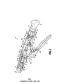
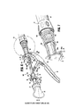
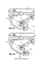
FIG.1is a top,side,perspective view from the distal end of the
presently disclosed surgical stapling apparatus;
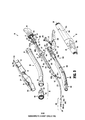
FIG.2is a side,perspective view of the handle portion of the
surgical stapling apparatus of FIG.1wherein one of the handle sections has been
removed to shown the internal components of the handle portion;
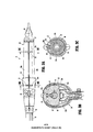
FIG.3is an exploded,perspective view of the surgical stapling
apparatus of FIG.1;
FIG.3A is a top view of the proximal end of the surgical stapling
apparatus of FIG.1;
FIG.3B is transverse,cross-sectional view taken along section line
3B-3B of FIG.3A;
FIG.3C is transverse,cross-sectional view taken along section line
3C-3C of FIG.3A;
FIG.3D is a side,perspective view of the proximal end of the
surgical stapling apparatus of FIG.1illustrating disengagement of the bushing
and the collar from the handle portion;
FIG.3E is an enlarged,cross-sectional view of the proximal end of
the surgical stapling apparatus of FIG.1illustrating the initial separation of the
handle sections of the handle portion from a closed position towards an open
position;
FIG.3F is an enlarged,perspective view of the handle portion of the
surgical stapling apparatus of FIG.1with the handle sections of the handle
portion disposed in an open position;
FIG.4is an enlarged view of the area of detail indicated as“4”in
FIG.1;
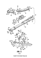
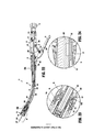
FIG.5is an exploded,perspective view of the approximation
assembly of the surgical stapling apparatus of FIG.1;
FIG.5A is a side perspective view of an embodiment of the set
screw of the tissue gap adjustment mechanism;
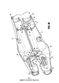
FIG.6is a side,perspective view of the proximal end of the handle
portion of the surgical stapling apparatus of FIG.1with the handle sections
removed and the proximal portions of the firing assembly and approximation
assembly illustrated;
FIG.7is an enlarged view of the area of detail indicated as“7”in
FIG.6;
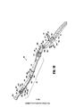
FIG.8is a side,perspective view of the approximation assembly of
the surgical stapling apparatus of FIG.1;
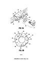
FIG.9is an enlarged view if the area of detail indicated as“9”in
FIG.8;
FIG.9A is an exploded,perspective view of the tissue gap
adjustment mechanism of the surgical stapling apparatus of FIG.1;
FIG.9B is an enlarged,top view of the adjustment washer of the
tissue gap adjustment mechanism of FIG.9A;
FIG.10is a perspective view of the staple pusher assembly of the
surgical stapling apparatus of FIG.1;
FIG.11is an exploded,perspective view of the staple pusher
assembly of FIG.10;
FIG.1lA is an enlarged,cross-sectional view of the proximal end of
the firing assembly with the trigger lock disposed in a locked position;
FIG.1lB is an enlarged,cross-sectional view of the proximal end of
the firing assembly with the trigger lock disposed in an unlocked position;
FIG.12is a side,perspective view from the distal end of the
elongated body portion of the surgical stapling apparatus of FIG.1;
FIG.13is an enlarged,perspective view of the proximal end of the
elongated body portion of FIG.12;
FIG.14is a perspective view from the distal end of the distal
bushing of the elongated body portion of FIG.12;
FIG.15is an exploded,perspective view of the elongated body
portion of FIG.12;
FIG.16is a perspective view from the proximal end of the proximal
bushing of the elongated body portion of FIG.12;
FIG.17is a perspective view of the distal end of the surgical
stapling apparatus of FIG.1including a safety cap disposed about the distal end
of the replaceable stapling assembly of the surgical stapling apparatus of FIG.1;
FIG.18is a perspective of the distal end of the surgical stapling
apparatus of FIG.1including the safety cap removed from the distal end of the
replaceable stapling assembly;
FIG.19is a perspective view from the proximal end of the
replaceable stapling assembly of the surgical stapling apparatus of FIG.1;
FIG.20is a perspective view from the distal end of the replaceable
stapling assembly of the surgical stapling apparatus of FIG.1;
FIG.21is an exploded,perspective view of the replaceable stapling
assembly of FIGS.19and20;
FIG.22is a longitudinal,cross-sectional view taken along section
line22-22of FIG.1;
FIG.23is an enlarged view of the area of detail indicated as“23”in
FIG.22;and
FIG.24is an enlarged view of the area of detail indicated as“24”in
FIG.22.
DETAILED DESCRIPTION OF EMBODIMENTS
Embodiments of the presently disclosed surgical stapling apparatus
will now be described in detail with reference to the drawings in which like
reference numerals designate identical or corresponding elements in each of the
several views.Throughout this description,the term″proximal″will refer to the
portion of the apparatus closest to the user and the term″distal″will refer to the
portion of the apparatus farthest from the user.
FIGS.1-24illustrate an embodiment of the presently disclosed
surgical stapling apparatus designated generally by reference numeral10.
Surgical stapling apparatus10includes a proximal handle portion20,an
elongated central body portion30,and a distal head portion40.Alternatively,it
may be desirable to have a substantially straight,shortened central body portion
in some surgical procedures,e.g.,the treatment of hemorrhoids.The length,
shape and/or the diameter of any of the proximal handle portion20,the central
body portion30,and the distal head portion40may also be selected to suit a
particular surgical purpose or procedure.Surgical stapling apparatus10further
includes an anvil assembly400coupled at the distal end of distal head portion
40.Anvil assembly400includes an anvil head assembly410and an anvil center
rod assembly420.Although not described in detail herein,anvil assembly400
may be configured to include any or all of the features of the anvil assemblies
described in the Milliman'187patent or the Gresham'444patent,previously
incorporated by reference herein in their entireties.
The various components of surgical stapling apparatus10described
hereinbelow are configured to facilitate the assembly and disassembly of
surgical stapling apparatus10,thus facilitating the disposal and replacement of
those components that are disposable and the sterilization and reassembly of
those components that are reusable.The materials used to form the various
components of surgical stapling apparatus10will depend upon the strength
requirements of the particular component and the use requirements of the
particular component,e.g.,whether the component is reusable or disposable.
The reusable components,for example,may generally be formed from
thermoplastics including polycarbonates,and metals including stainless steel and
aluminum,that are suited to withstand repeated sterilization procedures,e.g.,
autoclaving.
Referring to FIGS.1-3,proximal handle portion20of surgical
stapling apparatus10includes a stationary handle22,a firing trigger24,and a
rotatable approximation knob26.Stationary handle22is formed from first and
second releasably engagable handle sections22a,22b(FIG.3)that cooperate to
house and support the internal components of handle portion20,e.g.,the
proximal components of an approximation assembly200(FIG.3)and a firing
assembly300(FIG.3).Proximal handle portion20and the internal components
thereof will be described in greater detail below.
As mentioned above,stationary handle22is formed from first and
second handle sections22a,22b that cooperate to house and support the internal
components of handle portion20.Alternatively,stationary handle22may be
unitarily formed or formed from multiple handle sections.Handle sections22a,
22b can be configured as reusable,sterilizable components,or,alternatively,can
be configured as disposable components.
Referring specifically to FIG.3,each handle section22a,22b
includes a threaded distal extension22c,22d.Distal extensions22c,22d
cooperate to define a generally annular threaded member for releasably engaging
proximal bushing34of central body portion30.Engagement between distal
extensions22c,22d and proximal bushing34releasably secures outer tube32
and handle portion20to one another and also secures handle sections22a,22b
to one another at the distal ends thereof.As an alternative to threaded
engagement,proximal bushing34may be releasably engaged about distal
extensions22c,22d of handle sections22a,22b via any other suitable
mechanism including friction-fitting,snap-fitting,luer-locking,inter-fitting,etc.
Handle sections22a,22b further include threaded proximal extensions22e,22f,
respectively,that cooperate to define a generally annular threaded member for
releasably engaging collar27of approximation knob26.Similarly as above,
engagement between proximal extensions22e,22f and collar27rotatably
secures approximation knob26and handle portion20to one another and also
secures handle sections22a,22b to one another at the proximal ends thereof.
Collar27is rotatably secured to approximation knob26.Alternatively,collar27
can be formed separately from approximation knob26.
Referring also to FIGS.3A-3C,handle sections22a,22b are
pivotably coupled to one another via a pair of support members,e.g.,support
discs50,51,and a plurality of pin-slots engagements.Support discs50,51each
define an upper engagement portion52,53and a lower generally annular portion
54,55defining a respective aperture54a,55a.Upper engagement portions52,
53of support discs50,51are disposed within respective slots23a,23b(FIG.3A)
defined by cooperating slot portions of handle sections22a,22b.A pair of pins
56a,57a extend through respective apertures defined within handle sections22a,
22b on opposite sides of each of slots23a,23b and through slots56,57defined
through upper engagement portions52,53of support discs50,51to pivotally
secure handle sections22a,22b to support discs50,51and to one another.Slots
56,57are dimensioned to permit lateral translation of pins56a,57a along slots
56,57and relative to one another as well as rotation of pins56a,57a within slots
56,57.Apertures54a,55a defined by the lower portions54,55of support discs
50,51,respectively,are configured to receive rotatable sleeve210and indicator
bar270of approximation assembly200.The lower portions54,55of support
discs50,51are configured to position and support approximation assembly200
within stationary handle22.As will be described in detail below with respect to
the disassembly of stationary handle22,the slot-pin engagement of handle
sections22a,22b and support discs50,51allows for translational and rotational
movement of handle sections22a,22b relative to one another between a closed
position(FIG.3A),wherein stationary handle22encloses the proximal
components of approximation assembly200and firing assembly300,and an
open position(FIG.3F),wherein access to approximation assembly200and
firing assembly300is provided to facilitate replacement of any or all of such
components.
Referring to FIGS.4and5,stationary handle22defines an indicator
window25through which visual indicators276,278disposed on indicator bar
270may be viewed.Indicator window25may be formed via a hole or aperture
defined by one or both of handle sections22a,22b.Alternatively,indicator
window25may be formed from a transparent portion of one or both of handle
sections22a,22b.Visual indicators276,278are longitudinally-spaced along
indicator bar270and,when visible through indicator window25,indicate the
position of anvil assembly400(FIG.1)in relation to stapling assembly100,e.g.,
whether the anvil assembly400(FIG.1)is in a position spaced-apart from
stapling assembly100(visual indicator276)or an approximated position in
juxtaposed alignment with stapling assembly100(visual indicator278).
Approximation assembly200is detailed below.
Referring to FIGS.5-9,approximation assembly200of surgical
stapling apparatus10(FIG.1)includes an approximation knob26,a collar27,a
rotatable sleeve210,a drive screw220,a screw extension230,an anvil retainer
240,a screw stop250,and a tissue gap adjustment mechanism260.
Rotatable sleeve210includes a substantially cylindrical hollow
body portion211and a distal housing212that cooperate to define a central bore
213.A clip214is received within an annular groove214a formed about body
portion211.Support disc50,as mentioned above,is configured to receive body
portion211through aperture54a thereof.Clip214and distal housing212abut
support disc50on either side thereof to axially fix sleeve210and stationary
handle22relative to one another while permitting rotation of sleeve210in
relation to stationary handle22.
With particular reference to FIG.5,rotatable sleeve210further
includes a ball detent assembly215having a plug216and a detent member.In
an embodiment,the detent member includes a ball218.Ball218extends into
central bore213of rotatable sleeve210from a recess217of distal housing212
and is received in a helical channel221of drive screw220.Plug216includes a
body216a configured for receipt within recess217and defines a semi-spherical
concavity(not explicitly shown)for receiving a side of ball218opposite screw
220,and a head216b configured for engagement with distal housing212,e.g.,
via threaded-engagement,friction-fitting,etc.Once engaged with distal housing
212,plug216inhibits ball218from backing out of helical channel221of screw
220.In embodiments,the recess217can be defined only as a spherical recess
(not shown)on an inner wall of the distal housing212which is configured to
receive ball218.In this embodiment,the plug216is not required.
A proximal end of body portion211of rotatable sleeve210extends
through an opening21in a proximal end of stationary handle22.
Approximation knob26is affixed to the proximal end of body portion211of
rotatable sleeve210such that rotation of knob26causes concurrent rotation of
rotatable sleeve210.Approximation knob26may be releasably or permanently
affixed to rotatable sleeve210,e.g.,via snap-fitting,friction-fitting,an adhesive,
welding,and/or mechanical fasteners.Approximation knob26and/or the
proximal end of body portion211of rotatable sleeve210may include one or
more complementary protrusions and/or slots(not explicitly shown)to rotatably
fix approximation knob26relative to sleeve210.
Referring again to FIGS.5-9,a proximal portion220a of screw220
includes helical channel221and is dimensioned to be slidably positioned within
central bore213(FIG.5)of rotatable sleeve210.As mentioned above,ball218
(FIG.5)of ball detent mechanism215extends into helical channel221of screw
220.Since sleeve210is axially fixed with respect to stationary handle22,
rotation of sleeve210about screw220causes ball218(FIG.5)to move along
channel221of screw220to effect axial movement of screw220within
stationary handle22.Although shown having helical channel221configured to
receive ball218(FIG.5),it is envisioned that screw220may alternatively
include a helical thread(not shown)on an outer surface thereof configured to be
received within a channel or groove(not shown)formed on an inner surface of
sleeve210.Further,as an alternative to ball detent assembly215,approximation
assembly200may include a pin or other suitable mechanism for operably
coupling rotatable sleeve210and screw220to one another.
Distal portion220b of screw220defines a transverse slot227a and a
pair of throughbores227b formed perpendicular to transverse slot227a.
Transverse slot227a is configured to receive a proximal end of screw extension
230and throughbores227b are configured to receive pins226for securing
screw extension230to screw220.
Indicator bar270is positioned between proximal portion220a and
distal portion220b of screw220.Indicator bar270is seated within a
longitudinal recess272defined along screw220and may be secured therein in
any suitable manner,e.g.,via snap-fitting,friction-fitting,an adhesive,welding,
and/or mechanical fasteners.As detailed above,indicator bar270includes first
and second indicators276,278configured to be viewed through indicator
window25(FIG.4)to provide an indication that the anvil assembly400(FIG.1)
is in the spaced-apart position or the approximated position,respectively.
Indicators276,278may be of any suitable color(s),symbol(s)or may include
any other suitable feature,e.g.,reflective features,a light source(LED),etc.,to
facilitate the visualization of visual indicators276,278through window25(FIG.
4).Other suitable indicator mechanisms are disclosed in the Milliman'187
patent and the Gresham'444patent,previously incorporated by reference herein
in their entirety.
With continued reference to FIGS.5-9,screw extension230
includes a flexible flat band having proximal and distal portions232,234.
Although shown including only a single flexible flat band,it is envisioned that
screw extension230may include more than one flexible flat band.Alternately,
it is envisioned that screw extension230may have other than a flexible flat band
configuration.For example,screw extension230may be semi-circular or
circular in cross-section.The flexibility of screw extension230permits
movement of screw extension230through curved elongated outer tube32(FIG.
3).Proximal portion232of screw extension230includes a pair of holes233
dimensioned to receive pins226for securing proximal portion232of screw
extension230within transverse slot227a of screw220.Alternatively,other
fastening techniques may be used to secure screw extension230to screw220,
e.g.,welding,crimping,etc.Distal portion234of screw extension230is
configured to be received within a transverse slot241a formed in a proximal end
242of anvil retainer240to fasten anvil retainer240to distal end234of screw
extension230.In the illustrated embodiment,a pair of pins244extend through
a pair of openings241b defined in proximal end242of anvil retainer240and
holes235in distal portion234of screw extension230to secure screw extension
230to anvil retainer240.Alternately,distal portion234of screw extension230
may be secured within slot241a using any other fastening technique,e.g.,
screws,crimping,brazing,welding or the like,suitable for securing distal
portion234of screw extension230to anvil retainer240.
Anvil retainer240includes a trocar portion245a,a body portion
245b,and an attachment portion245c.Trocar portion245a includes a blunt
trocar tip247,although other configurations are also contemplated.Body
portion245b is substantially cylindrical and has a diameter which is larger than
the diameter of trocar portion245a.An annular protrusion248is disposed about
body portion245b of anvil retainer240and is configured to engage anvil
assembly400(FIG.1)to retain anvil assembly400(FIG.1)about anvil retainer
240.Alternatively,protrusion248need not be annular or may include different
attachment structure,e.g.,recesses,grooves,etc.
In use,when approximation knob26is manually rotated,rotatable
sleeve210is likewise rotated about the proximal portion220a of screw220.
Since sleeve210is axially fixed with respect to stationary handle22,and with
ball218(FIG.5)disposed within helical channel221of screw220,axial
rotation of sleeve210about screw220causes ball218to move along channel
221of screw220to thereby urge screw220to translate axially within stationary
handle22and relative to sleeve210.Upon axial translation of screw220,screw
extension230,which is fastened to the distal end of screw220,and anvil
retainer240,which is fastened to the distal end of screw extension230,are
moved axially through outer tube32of elongated body portion30.Thus,
referring particularly to FIG.1,with anvil assembly400releasably engaged
about the distal end of anvil retainer240,knob26may be rotated to effect
movement of anvil assembly400relative to stapling assembly100between an
unapproximated position spaced-apart from stapling assembly100and an
approximated position positioned adjacent to stapling assembly100.
With additional reference to FIGS.9A-9B,approximation assembly
200further includes a screw stop250disposed about screw220and configured
to function as a proximal stop for defining the minimum tissue gap between
anvil assembly400and stapling assembly100(see FIG.1).More specifically,
when stapling device10is in a fully approximated position,screw stop250
abuts at stop surface formed at the distal end of distal housing212of rotatable
sleeve210,inhibiting further proximal translation of screw220within stationary
handle22,thereby defining the minimum tissue gap between anvil assembly400
and stapling assembly100(see FIG.1).Tissue gap adjustment mechanism260
adjustably couples screw stop250to screw200to facilitate adjustment of the
minimum tissue gap by adjusting the longitudinal position of screw stop250on
screw220.Tissue gap adjustment mechanism260is described in detail below.
Tissue gap adjustment mechanism260,as mentioned above,is
configured to selectively adjust the longitudinal position of screw stop250on
screw220,thereby enabling discrete adjustment of the minimum tissue gap
between anvil assembly400and stapling assembly100(see FIG.1).In
particular,tissue gap adjustment mechanism260may be configured to permit
adjustment of the minimum tissue gap through a plurality of pre-determined
interval steps,e.g.,a step size of about0.15mm,between about4.55mm and
about5.45mm,although a greater or lesser range and/or greater or lesser interval
step sizes are also contemplated,depending on a particular surgical purpose.
Any suitable number of intervals and/or varying step sizes may also be provided.
As best shown in FIG.9A,tissue gap adjustment mechanism260
includes a set screw262and an asymmetrical polygonal washer264,e.g.,an
asymmetrical octagonal washer(although other configurations are also
contemplated).Screw stop250includes a housing252that defines a central
bore253configured to receive screw220,and a transverse slot254configured
to receive set screw262.First and second spaced-apart flanges255a,255b
extend transversely from housing252on either side of transverse slot254for
retaining asymmetrical washer264therebetween.Screw220includes a
threaded aperture228(FIG.5)configured to receive threaded shaft265of set
screw262to retain screw stop250in a fixed position about screw220.Head
266of set screw262includes a slot267configured to receive a screw driver
(not shown)or other suitable tool for driving set screw262into or out of
threaded aperture228.As opposed to a slot267,other suitable tool-engaging
features,e.g.,recesses and/or protrusions,are also contemplated.For example,
as shown in FIG.5A,the set screw262includes a polygonal head,e.g.,a
pentagonal head,configured to be engaged by a ratchet or wrench.Further,as
opposed to set screw262received within threaded aperture228(FIG.5)of
screw220,screw220may include a post(not shown)or other suitable feature
supported thereon for receipt within and longitudinal positioning relative to
transverse slot254of stop member250.
Referring to FIGS.9A-9B,asymmetrical washer264defines an
aperture268and includes a plurality of outer peripheral flats or sides269a-269h,
e.g.,eight sides,although greater or fewer sides are also contemplated.Due to
the asymmetrical configuration of washer264,the position of set screw262
within transverse slot254of screw stop250is varied depending on which
opposed sides269a-269h of washer264are positioned between flanges255a,
255b.With threaded aperture228of screw220receiving threaded shaft265of
set screw262,varying the position of set screw262within transverse slot254
likewise varies the longitudinal position of screw stop250relative to screw220,
thereby varying the size of the minimum tissue gap.For example,as the screw
stop250is moved proximally on the screw220,the minimum tissue gap is
increased because the screw stop250will engage sooner.Sides269a-269h may
include indicators256and flange255a may also include an indicator258to
allow the user to readily ascertain the setting of tissue gap adjustment
mechanism260.The minimum tissue gap corresponding to each setting of an
exemplary configuration of asymmetrical washer264is provided in the
following table,although other configurations are also contemplated.
With general reference to FIGS.5-9B,in order to adjust the
minimum tissue gap,stationary handle22(FIG.1)is disassembled(or prior to
assembly),set screw262is loosened,and asymmetrical washer264is rotated
about set screw262and relative to screw stop250to the desired position.Once
the desired position is achieved,set screw262may be re-tightened to maintain
screw stop250in the desired position on screw220,thus defining the desired
minimum tissue gap.As an alternative to disassembling stationary handle22
(FIG.1),a hole or opening may be provided in stationary handle22(FIG.1)to
provide direct access to tissue gap adjustment mechanism260without the need
to disassemble stationary handle22(FIG.1).Alternatively,the tissue gap
adjustment mechanism260can be preset to one of the predefined settings by the
manufacturer.
Firing assembly300will now be described with reference to FIGS.
10and11.Firing assembly300includes trigger24,a firing link310,and a
pusher linkage320.Pusher linkage320includes an elongated pusher tube330,
a pusher link340,and a pusher end tube350.Pusher linkage320is configured
for transferring force from proximal handle portion20(FIG.1)to distal head
portion40(FIG.1)to fire stapling assembly100(FIG.1).Although shown as a
three-part assembly,it is envisioned that pusher linkage320may include one or
more additional sections.Optionally,firing assembly300includes a trigger lock
360,which will be described in further detail below.
Trigger24is configured for operable engagement by a user.Trigger
24may support a cushioned gripping surface(not shown)formed of neoprene,
rubber or the like.The cushioned gripping surface provides a non-slip
cushioned surface to make actuation of stapling apparatus10(FIG.1)more
comfortable to a surgeon.Alternatively,trigger24may be formed of perforated
stainless-steel or other metal to facilitate sterilization.The distal end of trigger
24includes a pair of flanges304a,304b each defining an opening305a,305b,
respectively.Flanges304a,304b are configured for pivotal connection with a
pair of flanges324formed on proximal end330a of elongated pusher tube330
of pusher linkage320by a pivot member308a.Alternatively,pusher linkage
320may include a coupling member(not shown)integrally formed with or
fixedly secured to proximal end330a of pusher tube330for pivotally
connecting trigger24with pusher linkage320.
Trigger24further includes a lockout feature,e.g.,protrusion306,
extending from a distal end of trigger24adjacent flanges304a,304b.
Protrusion306is configured to engage the distal end of screw220(FIG.5)of
approximation assembly200(FIG.5)when approximation assembly200(FIG.
5)is in an unapproximated position to prevent accidental actuation of trigger24
before the anvil assembly(FIG.1)has been moved to the approximated position.
When approximation assembly200(FIG.5)is in the approximated position,
recess225(FIG.5)formed in the distal end of screw220(FIG.5)is in
alignment with protrusion306,thereby permitting actuation of trigger24,i.e.,
pivotal movement of trigger24about pivot member308a towards stationary
handle22.A biasing member(not shown)may also be provided for biasing
trigger24towards an unactuated position and for returning trigger24to the
unactuated position after firing.
Referring still to FIGS.10and11,trigger24further includes a first
opening30la,a second opening30lb,a notch301c,and an indicator member
309.First opening30la in trigger24is configured to receive a pin308b for
pivotally connecting trigger24with firing link310.Second opening30lb in
trigger24is configured to receive a pin308c for pivotally connecting trigger24
with trigger lock360.Notch301c is configured to releasably retain protrusion
362of trigger lock360therein to retain trigger lock360in an unlocked position.
Indicator member309is fixedly retained within a third opening308d and is
configured to engage an indicator member318of firing link310to provide an
audible and/or tactile indication to a user as stapling apparatus10(FIG.1)is
fired.
Firing link310includes a distal end312pivotally secured to trigger
24by a pivot member308b received through opening30la.A proximal end314
of firing link310supports a pivot member316which is pivotally secured within
a slot31(FIG.3)formed on each internal wall of handle sections22a,22b(FIG.
3).Alternatively,the pivot member316can be formed integrally with the firing
link310.Pivot member316is free to move vertically within slots31(FIG.3).
Although not shown,it is contemplated that a spring may be supported within
handle sections22a,22b(FIG.3)to urge pivot member316towards the bottom
of slot31(FIG.3),as provided in the Milliman'187patent,the contents of
which was previously incorporated by reference.Indicator member318is
formed on distal end312of firing link310and is configured to engage indicator
member309formed on trigger24during firing of stapling apparatus10(FIG.1),
as mentioned above.
As noted above,pusher linkage320includes an elongated pusher
tube330,a pusher link340and a pusher end tube350.A spring335received
about proximal end330a of elongated pusher tube330is configured to bias
pusher linkage320proximally to a retracted position.Spring335is retained
about proximal end330a of elongated pusher tube330via a ring member332
and a clip333,although other configurations for retaining spring225about
proximal end330a of elongated pusher tube330are also contemplated.Ring
member332is positionable distally of spring335and includes a pair of opposed,
inwardly-extending protrusions332a configured for slidable receipt within
elongated recesses332b defined on opposed sides of pusher linkage320.Clip
333is configured for engagement about proximal end330a of elongated pusher
tube330proximally of spring335.The ring member332sbuts an inner wall of
a distal end of stationary handle22(FIG.2)such that spring335urges clip333
and pushes linkage320proximally.
Distal end330b of pusher tube330includes a pair of flanges336a,
336b each defining an opening337a,337b,respectively.Each of openings337a,
337b is configured to receive a pivot pin338a,338b,respectively,to pivotally
secure a proximal end340a of pusher link340with distal end330b of elongated
pusher tube330.Pusher link340includes an elongated member defining a
channel341(FIG.22)extending substantially the length thereof.As shown,
pusher link340may be slightly curved along the length thereof.Channel341
(FIG.22)is configured to receive screw extension230of approximation
assembly200therethrough(FIG.5).Proximal end340a of pusher link340
includes a first pair of flanges342a,342b each defining an opening343a,(not
shown)sized to receive respective pivot pin338a,338b for pivotally connecting
pusher link340and elongated pusher tube330.A distal end340b of pusher link
340includes a second pair of flanges344a,344b,each defining an opening345a,
345b sized to receive a pivot pin348a,348b,respectively,for pivotally
connecting pusher link340and pusher end tube350.
A proximal end350a of pusher tube350includes a pair of flanges
352a,352b each defining an opening353a,353b configured for receiving
respective pivot pins348a,348b for pivotally connecting pusher tube350with
pusher link340.A distal end350b of pusher end tube350is configured to
selectively engage the stapling assembly100(FIG.1),as will be detailed below.
With reference to FIGS.l lA and l lB,as noted above,firing
assembly300may optionally include trigger lock360.Trigger lock360
includes a body360a and a base361defining a throughbore for receiving a pin
308c.Pin308c is received within the throughbore of base361to pivotably
couple trigger lock360to trigger24.Base361defines a radially asymmetric
configuration,e.g.,a tear-drop cross-sectional configuration,forming a pair of
contact surfaces361a,361b on either side of the throughbore that receives pin
308c.Trigger lock360further includes a protrusion362extending from body
360a of trigger lock360.Trigger lock360is rotatable relative to trigger24
between an unlocked position,wherein protrusion362is received within notch
301c(FIG.11)of trigger24,and a locked position,wherein protrusion362is
received within cut-out363(FIG.11)of trigger24and free end364of body
360a of trigger lock360is disposed in close approximation or abutting relation
with firing link310to inhibit actuation of trigger24.
A biasing member307,e.g.,a torsion spring,is disposed about pivot
member308b,which,as mentioned above,is received through opening30la of
trigger24and distal end312of firing link310to pivotally secured firing link
310to trigger24.Biasing member307includes a coiled portion307a and a flat
portion307b.Coiled portion307a is disposed about pivot member308b,while
flat portion307b extends proximally from coiled portion307a along trigger24.
Coiled portion307a biases flat portion307b towards trigger24.More
specifically,in the locked position of trigger lock360,as shown in FIG.1lA,
flat portion307b of biasing member307is biased into contact with contact
surface361a of base361of trigger lock360to urge trigger lock360in a
counter-clockwise direction as viewed in FIG.1lA.In this position,biasing
member307maintains trigger lock360in the locked position and inhibits
accidental dislodgment of trigger lock360from the locked position.In the
unlocked position of trigger lock360,as shown in FIG.1lB,flat portion307b of
biasing member307is biased into contact with contact surface361b of base361
of trigger lock360to urge trigger lock360in a clockwise direction as viewed in
FIG.1lB.In this position,biasing member307maintains trigger lock360in the
unlocked position and inhibits accidental dislodgment of trigger lock360from
the unlocked position.Thus,biasing member307establishes a bistable
configuration of trigger lock360,e.g.,wherein trigger lock360is stable in both
the locked position and the unlocked position.
Other suitable trigger locks are described in U.S.Patent7,303,106to
Milliman et al.,hereby incorporated by reference here,and the Milliman'187
patent and the Gresham'444patent,previously incorporated by reference herein.
Firing assembly300may further include a feedback mechanism similar to that
disclosed in the Milliman'187patent,previously incorporated by reference
herein.
With reference to FIGS.12-16,elongated central body portion30of
surgical stapling apparatus10(FIG.1)includes a curved elongated outer tube32,
a proximal bushing34(FIG.16),and a distal bushing36(FIG.14).Outer tube
32is configured to slidably receive components of approximation assembly200
(FIG.3)and firing assembly300(FIG.3).Proximal bushing34is rotatably
coupled about outer tube32via a ring37and is configured to enable releasable
threaded engagement of the proximal end of outer tube32with stationary handle
22of handle portion20(FIG.6).Distal bushing36,is engaged about the distal
end of outer tube32,e.g.,via friction-fitting,snap-fitting,adhesion,or other
suitable engagement,and is configured to enable releasable engagement of
replaceable stapling assembly100(FIG.3)with the distal end of outer tube32.
Referring to FIGS.17-21,distal head portion40of surgical stapling
apparatus10(FIG.1)includes anvil assembly400(FIG.1),described above,
that is releasably engagable with the distal end of approximation assembly200
(FIG.3),and a replaceable stapling assembly100that is releasably engagable
with the distal end of elongated central body portion30(FIG.3).A safety cap
500(FIGS.17-18)is also provided for engagement about the distal end of
replaceable stapling assembly100when not in use,e.g.,during shipping and
storage.Replaceable stapling assembly100(or portions thereof)is configured
as a disposable component that is to be replaced with a new replaceable stapling
assembly100(or portions thereof)after each firing.The remaining components
of surgical stapling apparatus t0(FIG.t)are configured as reusable,sterilizable
components,although one or more of these components may alternatively be
configured as a disposable component.Other configurations are also
contemplated.Distal head portion40will be described in greater detail below.
Replaceable stapling assembly t00will now be described in detail
with respect to FIGS.17-21.Referring initially to FIGS.17-18,and as
mentioned above,a safety cap500is provided for engagement about the distal
end of replaceable stapling assembly t00when not in use,e.g.,during shipping
and storage.Safety cap500includes a disc member510configured for
positioning about the distal end of stapling assembly t00,a pair of outer arms
520,530extending proximally from disc member5t0,and a pair of inner posts
540,550extending proximally from disc member5t0.Each outer arm520,530
includes an inwardly-extending protrusion522,532disposed at its free end.
Protrusions522,532are configured for receipt within apertures524defined
within outer housing portion104of shell assembly102of stapling assembly t00
to retain safety cap500about the distal end of stapling assembly t00.Arms520,
530may be formed from a resiliently flexible material so as to bias protrusions
522,532into apertures524,although other engagement mechanisms for
releasably retaining safety cap500about the distal end of stapling assembly t00
are also contemplated.Inner posts540,550are configured for insertion into
stapling assembly t00to help retain safety cap500in position about the distal
end of stapling assembly t00and to inhibit distal movement of pusher back t t0
(FIG.21)as will be described below to prevent the inadvertent ejection of
staples“S”(FIG.21)from stapling assembly t00during shipping or the like.
Referring to FIGS.19-21,replaceable stapling assembly t00
includes a shell assembly102,a pusher back t t0,a cylindrical knife120,and a
staple guide cap130.Shell assembly102includes an outer housing portion104
and an inner guide portion106.Outer housing portion104defines a
throughbore105and includes a distal cylindrical section104a,a central conical
section104b,and a proximal cylindrical section104c.Distal cylindrical section
104a includes a slot105a and a plurality of recesses105b.Slot105a is
configured to receive a protrusion132formed on staple guide cap130to
properly align staple guide cap130with pusher back110.Recesses105b are
configured for engagement with tabs134formed on staple guide130for
securing staple guide cap130to staple back110.
Proximal cylindrical section104c of outer housing portion104of
shell assembly102includes a pair of tabs108formed an inner surface thereof.
Tabs108are configured to selectively engage threads38(FIGS.15-16)formed
on the inner surface of distal bushing36(FIGS.15-16)to releasably theradably
engage shell assembly102and outer tube32(FIG.15)with one another.In this
manner,shell assembly102of stapling assembly100may be removed from
stapling apparatus10(FIG.1)subsequent to use and stapling apparatus10(FIG.
1)may be reloaded with another stapling assembly100and reused.
Pusher back110includes a central throughbore111which is
slidably positioned about inner guide portion106of shell102.Pusher back110
includes a distal cylindrical section110a which is slidably positioned within
distal cylindrical section104c of outer housing portion104,a central conical
section110b,and a proximal smaller diameter cylindrical section110c.Pusher
back110further includes a pair of proximally-extending arm members125.
Arm members125each include a finger127that is configured for insertion into
and locking engagement within annular recess128a of collar128disposed at
distal end350b of pusher end tube350of pusher link320(see FIG.11).Thus,
with pusher link320(FIG.11)engaged with pusher back110,actuation of firing
trigger24(FIG.11)urges pusher back l l0distally through outer housing
portion104to eject staples“S”from stapling assembly l00.
With particular reference to FIG.21,distal cylindrical section1l0a
of pusher back l l0includes a plurality of distally extending fingers114
dimensioned to be slidably received within slots131formed in staple guide cap
130to eject staples“S”therefrom.Distal ends l14a of fingers114define a
groove for engaging staples“S.”Cylindrical knife120is retained within central
throughbore111of pusher back1l0by a pair of tabs121.Alternately,knife
120may be retained within pusher back1l0using adhesives,crimping,pins,etc.
A distal end of knife120includes a circular cutting edge122.A rigid bushing
140is supported in the proximal end of inner guide portion106of shell102.
Bushing140defines a throughbore dimensioned to slidably receive anvil
retainer240(FIG.5)and center rod assembly420of anvil assembly400(FIG.
1).
In operation,when pusher linkage320(FIG.l0)is advanced distally
in response to actuation of trigger24(FIG.l0),pusher back1l0is advanced
distally within outer housing portion104of shell assembly102.Advancement
of pusher back110advances fingers114through slots131of staple guide cap
130to advance staples“S”positioned within slots131and eject staples“S”from
staple guide cap130into staple deforming pockets(not shown)formed on an
opposed surface of anvil head assembly410of anvil assembly400(FIG.1).
Since knife120is secured to pusher back l l0,knife120is also advanced
distally to core tissue.
The use of surgical stapling apparatus l0,disassembly of surgical
stapling apparatus l0for sterilization of the reusable components and
replacement of the disposable components,and reassembly of surgical stapling
apparatus10for subsequent use is now described.Adjustment of tissue gap
adjustment mechanism260(FIG.9A)is also described and may be effected
during manufacturing,assembly,between uses,or at any other suitable point
where setting and/or changing the minimum tissue gap is desired.
With general reference to FIGS.1and22,in use,safety cap500
(FIGS.17-18)is initially removed from the distal end of stapling assembly100.
Next,distal head portion40of surgical stapling apparatus10inserted into an
internal surgical site,before or after engagement of distal head portion40with
the anvil assembly400.Next,anvil assembly400and stapling assembly100are
positioned adjacent tissue to be stapled.At this point,anvil assembly400is in
an unapproximated position and screw220of approximation assembly200
(FIGS.5-9)is in its distal-most position.This position of anvil assembly400
may be visually confirmed by viewing indicator276of indicator bar270(FIG.3)
through window25(FIG.4)formed in stationary handle22.As shown in FIG.
2,trigger lock360is disposed in the locked position at this point such that
actuation of firing trigger24is inhibited.Trigger24is further prevented from
being actuated by engagement of protrusion306(FIGS.10-11)of trigger24
with screw220(FIGS.5-9),as detailed above.
Once distal head portion40of surgical stapling apparatus10is
positioned as desired,anvil assembly400may be approximated relative to
stapling assembly100to clamp tissue therebetween via manipulating
approximation knob26.Tissue can be secured between anvil assembly400and
stapling assembly100using conventional techniques such as using purse-string
sutures,resilient bands,or the like.Knob26may be rotated to approximate
anvil assembly400relative to stapling assembly100to clamp tissue
therebetween until the minimum tissue gap between anvil assembly400and
stapling assembly100,which is set via tissue gap adjustment mechanism260
(FIG.9A),is achieved.Movement of the anvil assembly400to the
approximated position can be visually confirmed once visual indicator278(FIG.
3)is viewable through window25(FIG.4).
With anvil assembly400disposed in the approximated position and
tissue clamped between anvil head410and staple guide cap130of stapling
assembly100,firing assembly300(FIGS.10-11)may be actuated to staple and
core the clamped tissue.In order to allow for firing,trigger lock360is rotated
from the locked position to the unlocked position.In the approximated position
of anvil assembly400,recess225formed in screw220of approximation
assembly200(see FIGS.5-9)is aligned with protrusion306(FIGS.10-11)
formed on trigger24to permit actuation of trigger24,provided trigger lock260
is disposed in the unlocked position.
With trigger lock360and protrusion306(FIGS.10-11)no longer
inhibiting actuation of trigger24,surgical stapling apparatus10may be actuated.
In order to fire stapling apparatus10,trigger24is compressed towards
stationary handle22,which urges pusher link assembly320(FIGS.10-11)
distally through outer tube32to urge pusher back110(FIG.21).With
additional reference to FIG.21,distal translation of pusher back110relative to
staple guide cap130urges pusher back110to engage and eject staples“S”from
staple guide cap130,through tissue,and into anvil head410of anvil assembly
400,which form staples“S”about tissue.Knife120is moved concurrently with
pusher back110such that knife120is likewise advanced distally to core tissue.
Continuing with general reference to FIGS.1and22,in one
exemplary method of use,surgical stapling apparatus10is used to perform a
circular anastomosis.Typically,circular anastomoses are required during
procedures for removing a portion of a diseased vessel such as the colon or the
intestine.During such a procedure,the diseased portion of the vessel is removed
and the end portions of the remaining first and second vessel sections are joined
together using the surgical stapling apparatus10.
During such a procedure using the surgical stapling apparatus10,
prior to removing the diseased vessel portion from the diseased vessel,anvil
assembly400with a removable trocar(not shown)attached thereto is positioned
in the first vessel section on a first side of the diseased portion.A removable
trocar which is suitable for use with anvil assembly400is disclosed in the
Gresham'444patent,which,as discussed above,is incorporated herein by
reference in its entirety.After the diseased vessel portion is removed and the
open ends of the first and second vessel sections have been sutured,the distal
end of apparatus10is positioned in the second vessel section on the other side of
the diseased vessel portion which has been removed.At this time,the
removable trocar is pushed through the suture line in the end of the first vessel
section and removed from the anvil assembly.Next,trocar tip247of anvil
retainer240is pushed through the suture line in the second vessel section and is
joined to the center rod of the anvil assembly400.The surgical stapling
apparatus10can now be approximated and fired in the manner discussed above
to join the ends of the first and second vessel sections and core out any tissue
obstructing the vessel lumen.
At the completion of the stapling operation,surgical stapling
apparatus10may be removed from the internal surgical site.More specifically,
anvil assembly400may be configured to pivot to a low-profile configuration
after firing and upon un-approximation of anvil assembly400relative to stapling
assembly100to facilitate removal of surgical stapling apparatus10from the
internal surgical site.A suitable tilting mechanism is described in the
Milliman'187patent or the Gresham'444patent,previously incorporated by
reference herein in their entirety.Alternatively,anvil assembly400need not
have a pivotal head and may be removed from the surgical site in the same
orientation as it was advanced into the surgical site.
Upon removal from the internal surgical site at the completion of the
surgical procedure(or prior to use),surgical stapling apparatus10may be
disassembled to facilitate sterilization of the reusable components and
replacement of the disposable components.Adjustment of tissue gap adjustment
mechanism260(FIG.9A)may also be effected at this time.
Referring still to FIGS.1and22,to disassemble surgical stapling
apparatus10,anvil assembly400is first removed from anvil retainer240by
moving anvil assembly400to the unapproximated position and separating anvil
assembly400from anvil retainer240using sufficient force to disengage center
rod assembly420from annular protrusion248(FIG.5).Anvil assembly400is
configured as a sterilizable,reusable component although it is also contemplated
that anvil assembly be configured as a reusable component.
Once anvil assembly400has been removed,stapling assembly100
may be disengaged from surgical stapling apparatus10.More specifically,
stapling assembly100is disengaged from the distal end of outer tube32by
rotating shell assembly102relative to outer tube32to disengage tabs108(FIGS.
20-21)from threads38(FIG.16)of distal bushing36.Thereafter,shell
assembly102is squeezed inwardly and translated distally to disengage fingers
127(FIGS.20-21)of arms125(FIGS.20-21)from collar128of distal pusher
end350(FIG.11)to fully disengage stapling assembly100from outer tube32.
Once disengaged,stapling assembly100may then be removed from positioning
about anvil retainer240and may be disposed of,although it is also contemplated
that one or more components of stapling assembly100be sterilizable for reuse.
Referring to FIGS.3D-3F,in order to disassemble stationary handle
22in preparation for sterilization,proximal bushing34is disengaged from the
distal ends of handle sections22a,22b by rotating proximal bushing34relative
to stationary handle22,and collar27is disengaged from the proximal ends of
handle sections22a,22b by rotating collar27relative to stationary handle22.
Once proximal bushing34and collar27have been disengaged from the
proximal and distal ends of stationary handle22,handle sections22a,22b may
be moved relative to one another from the closed position(FIG.3D)to the open
position(FIG.3F).
In order to move handle sections22a,22b from the closed position
(FIG.3D)to the open position(FIG.3F),handle sections22a,22b are initially
moved apart from one another and relative to discs50,51(see FIG.3E with
respect to disc50).In particular,handle sections22a,22b are translated apart
from one another and relative to discs50,51such that pins56a,57a are
translated from the inner ends of slots56,57(FIGS.3B and3C)to the outer
ends of slots56,57,respectively.This outward translation of handle sections
22a,22b provides clearance between handle sections22a,22b and the internal
components retained within stationary handle22.More specifically,the
outward translation of handle sections22a,22b withdraws pivot member316
from slots31(FIG.2)and withdraws the wings of proximal end330a of
elongated pusher tube330from the channels defined within handle sections22a,
22b(FIG.3).
Once sufficient clearance has been achieved between handle sections
22a,22b and the internal components of handle portion20,the free sides of
handle sections22a,22b,i.e.,the sides of handle sections22a,22b opposite the
pin-slot engagement of handle sections22a,22b and discs50,51,are rotated
apart from one another about pins56a,57a relative to support discs50,51to the
open position.In the open position of handle sections22a,22b,the proximal
components of approximation assembly200and firing assembly300are
exposed,facilitating adjustment and/or removal of any or all of these
components,as detailed below.
With momentary reference to FIG.9A,at this point,if it is desired to
change the minimum tissue gap setting,set screw262is loosened,and
asymmetrical washer264is rotated about set screw262and relative to screw
stop250to the desired position.Once the desired position is achieved,set screw
262may be re-tightened to maintain screw stop250in the desired position on
screw220,thus defining the desired minimum tissue gap.
Referring to FIGS.1,2,and22,once handle sections22a,22b have
been pivoted to the open position(FIG.3F),approximation assembly200and
firing assembly300may be removed from stationary handle22.Thus,with
stationary handle22opened,and with approximation assembly200and firing
assembly300removed from handle portion,sterilization of each of these
components for reuse may be readily achieved.Alternatively,one or more of
theses components may be configured as a disposable component and,thus,may
be replaced with a new component rather than being sterilized.Additionally or
alternatively,sterilization may be effected with stationary handle22in the open
position(FIG.3F)but without the need to remove approximation assembly200
and/or firing assembly300.
Once the reusable components,e.g.,handle sections22a,22b,
approximation assembly200,and firing assembly300,have been sterilized and
the replaceable components,e.g.,stapling assembly100,replaced,surgical
stapling apparatus10may be reassembled for subsequent use in reverse order of
disassembly.As can be appreciated,the above-described cycle of use,
disassembly,sterilization and replacement,adjustment,and reassembly,may be
repeated for a plurality of usage cycles.
It will be understood that various modifications may be made to the
embodiments of the surgical stapling apparatus disclosed herein.Therefore,the
above description should not be construed as limiting,but merely as
exemplifications of embodiments.Those skilled in the art will envision other
modifications within the scope and spirit of the present disclosure.