WO2015178879A1 - Synchronized light source for rolling shutter imagers - Google Patents
Synchronized light source for rolling shutter imagers Download PDFInfo
- Publication number
- WO2015178879A1 WO2015178879A1 PCT/US2014/038563 US2014038563W WO2015178879A1 WO 2015178879 A1 WO2015178879 A1 WO 2015178879A1 US 2014038563 W US2014038563 W US 2014038563W WO 2015178879 A1 WO2015178879 A1 WO 2015178879A1
- Authority
- WO
- WIPO (PCT)
- Prior art keywords
- lamp
- imager
- lighting system
- line
- signal
- Prior art date
Links
Classifications
-
- G—PHYSICS
- G03—PHOTOGRAPHY; CINEMATOGRAPHY; ANALOGOUS TECHNIQUES USING WAVES OTHER THAN OPTICAL WAVES; ELECTROGRAPHY; HOLOGRAPHY
- G03B—APPARATUS OR ARRANGEMENTS FOR TAKING PHOTOGRAPHS OR FOR PROJECTING OR VIEWING THEM; APPARATUS OR ARRANGEMENTS EMPLOYING ANALOGOUS TECHNIQUES USING WAVES OTHER THAN OPTICAL WAVES; ACCESSORIES THEREFOR
- G03B9/00—Exposure-making shutters; Diaphragms
- G03B9/70—Exposure-making shutters; Diaphragms with flash-synchronising contacts
-
- H—ELECTRICITY
- H04—ELECTRIC COMMUNICATION TECHNIQUE
- H04N—PICTORIAL COMMUNICATION, e.g. TELEVISION
- H04N23/00—Cameras or camera modules comprising electronic image sensors; Control thereof
- H04N23/50—Constructional details
- H04N23/555—Constructional details for picking-up images in sites, inaccessible due to their dimensions or hazardous conditions, e.g. endoscopes or borescopes
-
- H—ELECTRICITY
- H04—ELECTRIC COMMUNICATION TECHNIQUE
- H04N—PICTORIAL COMMUNICATION, e.g. TELEVISION
- H04N23/00—Cameras or camera modules comprising electronic image sensors; Control thereof
- H04N23/56—Cameras or camera modules comprising electronic image sensors; Control thereof provided with illuminating means
-
- H—ELECTRICITY
- H04—ELECTRIC COMMUNICATION TECHNIQUE
- H04N—PICTORIAL COMMUNICATION, e.g. TELEVISION
- H04N23/00—Cameras or camera modules comprising electronic image sensors; Control thereof
- H04N23/70—Circuitry for compensating brightness variation in the scene
- H04N23/74—Circuitry for compensating brightness variation in the scene by influencing the scene brightness using illuminating means
-
- G—PHYSICS
- G03—PHOTOGRAPHY; CINEMATOGRAPHY; ANALOGOUS TECHNIQUES USING WAVES OTHER THAN OPTICAL WAVES; ELECTROGRAPHY; HOLOGRAPHY
- G03B—APPARATUS OR ARRANGEMENTS FOR TAKING PHOTOGRAPHS OR FOR PROJECTING OR VIEWING THEM; APPARATUS OR ARRANGEMENTS EMPLOYING ANALOGOUS TECHNIQUES USING WAVES OTHER THAN OPTICAL WAVES; ACCESSORIES THEREFOR
- G03B2215/00—Special procedures for taking photographs; Apparatus therefor
- G03B2215/05—Combinations of cameras with electronic flash units
- G03B2215/0564—Combinations of cameras with electronic flash units characterised by the type of light source
- G03B2215/0567—Solid-state light source, e.g. LED, laser
-
- H—ELECTRICITY
- H04—ELECTRIC COMMUNICATION TECHNIQUE
- H04N—PICTORIAL COMMUNICATION, e.g. TELEVISION
- H04N25/00—Circuitry of solid-state image sensors [SSIS]; Control thereof
- H04N25/50—Control of the SSIS exposure
- H04N25/53—Control of the integration time
Definitions
- This invention relates generally to the field of medical video equipment. More specifically, the invention comprises a synchronized light source for rolling shutter imagers, i.e. a control system for an LED light source for use with an endoscopic or similar camera system with a CMOS-type imager.
- a synchronized light source for rolling shutter imagers i.e. a control system for an LED light source for use with an endoscopic or similar camera system with a CMOS-type imager.
- Control of the intensity of this light is important for various functional and safety reasons. Improper light levels can cause under-exposure or over-exposure, forcing the camera system to overcompensate in ways that reduce or limit the image quality and camera performance. Safety concerns involving high light transmission can include skin and tissue burns, and possible ignition of flammable materials.
- LED Light-Emitting Diode
- PWM Pulse-Width Modulation
- the PWM method of light intensity control works well with video cameras with frame-transfer imagers such as CCDs (Charge-Coupled Devices), so long as the switching frequency of the light is equal or greater than the camera's rate of frame capture, typically 60 exposures per second for a video camera. It is convenient to use an integer multiple of the frame rate, such as double, for the PWM switching frequency. It is also beneficial to synchronize the light source with the camera's frame rate to avoid a frequency mismatch with can result in a beating, flickering or "strobing" image.
- CCDs Charge-Coupled Devices
- CMOS imagers with a "rolling-shutter"-type exposure architecture the most common type, as these are not frame-transfer devices. Instead, each line of the raster image is exposed in a cascading overlapped sequence, with lines being read out while other lines are exposing. The exposure of one line will thusly never start and stop at the same time as another line, even though the resultant time duration is same, and their exposures will overlap one another in time.
- the invention resides in a lighting system adapted for use with a rolling shutter imager having a horizontal line rate comprising: a lamp; a drive circuit coupled to the lamp capable of energizing the lamp for switching the lamp on and off; and a lamp control circuit coupled to the drive circuit with a means for receiving a line timing signal from an imaging system, the lamp control circuit synchronously energizing the lamp with the line timing signal via the drive circuit, the line timing signal being based upon the horizontal line rate of the imager.
- the invention resides in an illumination control system for passing timing information to a lighting system from an imaging system utilizing a rolling shutter imager operating at a horizontal line rate, comprising: an electronic connector; and a digital electronic signal carried by the electronic connector wherein digital pulses are timed to be synchronous with the horizontal line rate of the imager.
- the invention resides in an illumination control system for passing timing information to a lighting system from an imaging system utilizing a rolling shutter imager operating at a horizontal line rate and a pixel clock rate, comprising: an electronic connector; and a digital electronic signal carried by connector wherein the signal is a clock derived from the pixel clock rate, wherein the lighting system utilizes foreknowledge of the horizontal line rate timing of the imager to derive the horizontal line rate from the clock signal.
- FIG. 1 is a block diagram of a presently preferred embodiment of the present invention.
- FIG. 2 is a timing diagram illustrating various timing relationships of the signals in the embodiment of FIG. 1.
- FIG. 3 is a block diagram of an illumination control system for passing timing information from an imaging system to a lighting system (that may or may not be integrated within a common housing or on a common circuit board), in the exemplary context of an endoscopic video camera system where the imaging system includes a rolling shutter imager operating at a horizontal line rate and where the lighting system receives a digital electronic signal having digital pulses that are synchronous with the horizontal line rate of the rolling shutter imager; and
- FIG. 4 is a block diagram of an illumination control system for passing timing information from an imaging system to a lighting system that is similar to FIG. 3, where the imaging system includes a rolling shutter imager operating at a horizontal line rate and, in more detail, at a pixel clock rate, and where the lighting system receives a digital electronic signal corresponding to a clock signal oscillating at the pixel clock rate and where the lighting system contains suitable processing capability to derive the horizontal line rate of the imager from the clock signal and other known parameters.
- the imaging system includes a rolling shutter imager operating at a horizontal line rate and, in more detail, at a pixel clock rate, and where the lighting system receives a digital electronic signal corresponding to a clock signal oscillating at the pixel clock rate and where the lighting system contains suitable processing capability to derive the horizontal line rate of the imager from the clock signal and other known parameters.
- FIG.l shows a block diagram of a presently preferred embodiment of the invention.
- the illustrated embodiment, and others, is based on the foundational observation that a "rolling shutter” imager can be said to have a “horizontal line rate” while operating, the rate at which entire horizontal lines of raster data are read out.
- the imager has a "pixel clock rate", the rate at which each pixel within a line is individually read or “clocked” out from the sensor, this pixel clock rate typically being hundreds to thousands of times faster than the line rate.
- the line rate is directly tied to the sensor's shutter mechanism, and therefore the exposure, as the amount of time exposure of a line is changed by increasing or decreasing the number of lines between when the line is read out, and when it is to start exposing again, or ceases being cleared.
- the preferred embodiment relates to an endoscopic or similar video system that comprises a camera having a Rolling Shutter Imager 103 and a Light Source 114 that is pulsed on and off with a PWM signal 111 and associated drive circuitry 112 in order to strategically illuminate the subject matter that is focused onto the Rolling Shutter Imager 103.
- the Rolling Shutter Imager 103 is implemented with a CMOS imager.
- CMOS imager CMOS imager
- other imager technologies may use a rolling shutter approach to exposure.
- the preferred Light Source 114 is comprised of one or more LEDs, but the preferred and/or alternative embodiments may be implemented with any suitable light source that now exists or is later developed. It should be understood, therefore, that any reference to an LED is a reference to any suitable light source.
- Camera Timing Logic 101 provides timing signals 102 to the rolling shutter imager 103 (e.g. a CMOS Imager) which generates an Imager Video Signal 104.
- Image Processor 105 processes the Imager Video Signal 104, and generates a Video Output Signal 106 that drives a Video Output Device 107, and an Intensity Signal 109 that is fed back to the Lamp Control Logic 110, which indicates whether more or less light is desired from LED 114 in order to achieve a desired exposure.
- the Camera Timing Logic 101 also provides a Line Timing Signal 108, which is used by the Lamp Control Logic 101 to synchronize a PWM signal 111 to the Drive Circuitry 112, which in turn outputs the Drive Current Pulses 113 to the light source 114 (e.g. LED) in linear correlation to the PWM signal 111.
- a PWM signal 111 to the Drive Circuitry 112
- the Drive Current Pulses 113 to the light source 114 (e.g. LED) in linear correlation to the PWM signal 111.
- FIG. 2 shows a typical timing relationship of some signals of the preferred embodiment.
- a line timing signal 201 (e.g. HSYNC), generated by Camera Timing Logic 101 is applied to the Lamp Control logic 110 to generate the time-base and synchronicity of the drive current pulses 113.
- An Intensity Signal 202 is applied, which may be an analog signal (as shown) or a digital signal. This Intensity signal 202 is interpreted by the Lamp Control Logic 110 to determine the relative duty cycle or percent intensity.
- the Lamp Control Logic 110 outputs the PWM signal 203 which is used to drive the Light Source 113, e.g.
- LED emitter current with LED Drive Current Pulses which has timing based upon the timing of HSYNC and a duty cycle based upon the Intensity Signal 202, wherein the more intensity indicated by the Intensity Signal 202, the longer the PWM signal 111 remains in the active, or current-driving state.
- FIGS. 1 and 2 may be
- a medical imaging device e.g. an endoscopic video camera with a CMOS imager having a rolling shutter; a light source using an LED for illumination of the scene to be imaged by said camera; LED drive circuitry, typically comprising transistors or similar current-switching devices; control circuitry with a means of controlling the average LED light output intensity using a PWM technique to control said LED drive circuitry, and a signal from the camera to the control circuitry that is synchronous to the rate of line readout of the CMOS imager.
- the control circuitry flashes the LED on and off at a rate based upon the line frequency of the CMOS imager exposure system, where one pulse (or plurality of pulses) happens per unit time elapsed while a line of the CMOS imager is read and restarts its exposure before moving on to the next line. For example, if a standard HD imager with 1920 horizontal pixels by 1080 vertical lines were to be exposed and read at 60 frames per second, the line frequency would be 1080 (number of lines per frame) times 60 (number of frames per second) which is equal to 64,800 lines per second, or approximately one line every 15.432usec.
- a timing circuit would generate a pulse synchronous with this line rate of the CMOS imager, what would typically be called a digital horizontal sync pulse, commonly known as HSYNC. It should be noted that this HSYNC pulse is not typically the same as the HSYNC signal or timing element of the output video of the camera, as rolling shutter imagers typically are not, and in many cases cannot be, operated line-synchronously with conventional video transport standards, an example of which is the 1080p video format as outlined in SMPTE-274M.
- the control circuitry would receive this imager HSYNC digital pulse from the imaging system, typically by means of an electrical cable and electrical connectors, and use its frequency and position in time as the PWM time base.
- control circuitry By means of the drive circuitry, the control circuitry a pulses the LED current at this frequency and position in time with the duty cycle of each drive pulse equivalent to the desired percent intensity desired from the LED, as determined by direct user input or calculated by camera processing.
- An illustration of one potential timing implementation can be found in Figure 2.
- PWM of conventional systems an LED with appropriate on and off response times is required, along with drive circuitry capable of driving high LED currents at this rate with pulse widths of possibly very short duration.
- the drive circuitry of a this line-based system would typically consume more power and dissipate more heat as opposed to a frame -based system, as it has as to drive many more off-to-on and on-to-off transitions per frame, each of which will dissipate heat in the device as it switches in an analog fashion between states.
- Figures 3 represents a typical medical endoscopy situation where the Imaging
- the illumination control system that carries the horizontal line rate signal between the two systems. This would typically be physically implemented by an electrical connector present on both systems, and an electrical cable between.
- the signal passed between the systems is a digital pulse representation of the horizontal line rate of the imager in the imaging system.
- the lighting system 30 Based on this signal, the lighting system 30 synchronously energizes the related light source (e.g. LEDs or other lamps) with the horizontal line rate of the imaging system 20.
- Figure 4 represents a system very similar to one in Figure 3, with the exception that the signal passed from the imaging system to the lighting system is a clock signal, based upon the pixel clock rate of the imager.
- the lighting system 30 includes a suitable means for deriving the horizontal line rate from the clock signal.
- the lighting system would require some foreknowledge of the timing of the imager and the imaging system, which could be programmed into the lighting system, or passed to the lighting system from the imaging system be means of another electrical interface, such as a serial communications port.
- the signal from the camera to the control circuitry is the video output of the camera itself, and the control circuitry extracts the PWM time base from the line interval of the video signal, which may be of a video standard such as SMPTE 274M.
- This embodiment allows for a more generic interface between the camera and the control circuitry, such that the two devices may use standard interfaces to achieve the proper synchronization. This has the potential advantage of less specialized and dedicated interface, as it can be done without direct interface to the imager timing logic.
- This embodiment is advantageous when the light source and camera elements of the system are not contained in the same unit or enclosure. For best results this method requires the same time relationship between the imager line rate and the output video line rate. These may not always be the exactly the same duration or
- this interface has the additional advantage of also carrying the picture level information, as it is the video itself, and therefore the lighting system would have the information required to adjust the brightness of the light automatically, should this be desired.
- Another embodiment of the invention would be in the case where there is a duration of time where lines of the CMOS imager are not being read out, and all lines of the image are being exposed.
- This is a common practice in a multiple frame rate imaging system, such as one that operates at both 50 and 60 frames per second, dependent on the video standard of the country that the imaging system is being used in.
- this duration where all lines are being exposed can be 16% of the total frame duration, but may also be longer or shorter by design.
- the LED may continue to be pulsed at the same frequency that would otherwise correspond to the horizontal line frequency as if the lines were being read out at this rate.
- the LED may also be turned off or on entirely during this idle time.
- the LED may also be turned on for a portion of this time, either in a pulsed or constant fashion, for either a fixed or variable percentage of this idle time, which may or may not correspond to the duty cycle or frequency used during the non-idle period of the frame.
- Another embodiment of the invention would be the case where the lamp is modulated on and off on a line -by-line basis.
- the lamp would be turned on for single or multiple lines, alternating with being turned off for the subsequent line or multiple lines.
- the advantage of this type of system is that a slower, and therefore less expensive, drive circuit may be employed, as the pulses are longer by nature, or where the lamp itself cannot be turned on and off at the faster rates of the aforementioned embodiments.
- This further has the advantage of lower frequency radiated and conducted emissions created by the high power switching.
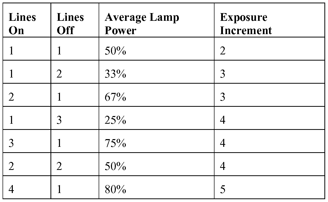
- the disadvantage of this type of line modulation is that to achieve completely uniform exposure across all lines or regions of the image, the time of the imager's total light exposure can only be increased or decreased by the factor of the number of lines on, plus the number of lines off. For example, if a power output of 75% is desired from the lamp, it may be flashed such that it is on for three lines, and off for one line.
- the rolling shutter should be set such that the exposure time is in increments of four lines, to ensure that all lines receive a 3: 1 ratio of lamp on-time to lamp off-time.
- the fewer lines to create the power ratio needed the more increments of shutter are usable for a given number of horizontal imager lines.
- the minimum exposure increment is two lines, alternating one line on and on line off, to achieve a 50% light output from the lamp. Most sensors have an even number of horizontal image lines, but odd numbered increments of shutter exposure can be used if they divide evenly into the total number of imager lines.
- a 1080-line system is common for HD, and as the number 1080 has 3 and 5 as factors, these exposure increments would be feasible.
- the 2:2 line ratio is of note, as it yields the same lamp power result as the 1 : 1 line ratio, but it flashes the lamp at half the frequency.
- the on and off times being slower, an even slower drive circuit or lamp could be utilized, at the cost of higher exposure increment.
Landscapes
- Engineering & Computer Science (AREA)
- Multimedia (AREA)
- Signal Processing (AREA)
- Physics & Mathematics (AREA)
- General Physics & Mathematics (AREA)
- Studio Devices (AREA)
- Exposure Control For Cameras (AREA)
- Stroboscope Apparatuses (AREA)
- Endoscopes (AREA)
Abstract
Description
Claims
Priority Applications (4)
| Application Number | Priority Date | Filing Date | Title |
|---|---|---|---|
| JP2017514251A JP2017525304A (en) | 2014-05-19 | 2014-05-19 | Synchronous light source for rolling shutter image sensor |
| CA2949362A CA2949362A1 (en) | 2014-05-19 | 2014-05-19 | Synchronized light source for rolling shutter imagers |
| PCT/US2014/038563 WO2015178879A1 (en) | 2014-05-19 | 2014-05-19 | Synchronized light source for rolling shutter imagers |
| EP14892253.7A EP3146713A4 (en) | 2014-05-19 | 2014-05-19 | Synchronized light source for rolling shutter imagers |
Applications Claiming Priority (1)
| Application Number | Priority Date | Filing Date | Title |
|---|---|---|---|
| PCT/US2014/038563 WO2015178879A1 (en) | 2014-05-19 | 2014-05-19 | Synchronized light source for rolling shutter imagers |
Publications (1)
| Publication Number | Publication Date |
|---|---|
| WO2015178879A1 true WO2015178879A1 (en) | 2015-11-26 |
Family
ID=54554408
Family Applications (1)
| Application Number | Title | Priority Date | Filing Date |
|---|---|---|---|
| PCT/US2014/038563 WO2015178879A1 (en) | 2014-05-19 | 2014-05-19 | Synchronized light source for rolling shutter imagers |
Country Status (4)
| Country | Link |
|---|---|
| EP (1) | EP3146713A4 (en) |
| JP (1) | JP2017525304A (en) |
| CA (1) | CA2949362A1 (en) |
| WO (1) | WO2015178879A1 (en) |
Citations (3)
| Publication number | Priority date | Publication date | Assignee | Title |
|---|---|---|---|---|
| US7667740B2 (en) * | 2006-07-28 | 2010-02-23 | Hewlett-Packard Development Company, L.P. | Elimination of modulated light effects in rolling shutter CMOS sensor images |
| US8218068B2 (en) * | 2009-04-01 | 2012-07-10 | Omnivision Technologies, Inc. | Exposing pixel groups in producing digital images |
| US20140014820A1 (en) * | 2012-04-16 | 2014-01-16 | Olympus Medical Systems Corp. | Image pickup system and image pickup method |
Family Cites Families (3)
| Publication number | Priority date | Publication date | Assignee | Title |
|---|---|---|---|---|
| JP2007318581A (en) * | 2006-05-29 | 2007-12-06 | Casio Comput Co Ltd | Imaging apparatus, photographing auxiliary light source emitting/imaging control method, and photographing auxiliary light source emitting/imaging control program |
| WO2013146858A1 (en) * | 2012-03-28 | 2013-10-03 | 富士フイルム株式会社 | Imaging device, and endoscope device provided therewith |
| JP6006147B2 (en) * | 2012-03-28 | 2016-10-12 | 富士フイルム株式会社 | Imaging device and endoscope apparatus provided with the same |
-
2014
- 2014-05-19 WO PCT/US2014/038563 patent/WO2015178879A1/en active Application Filing
- 2014-05-19 EP EP14892253.7A patent/EP3146713A4/en not_active Withdrawn
- 2014-05-19 CA CA2949362A patent/CA2949362A1/en not_active Abandoned
- 2014-05-19 JP JP2017514251A patent/JP2017525304A/en active Pending
Patent Citations (3)
| Publication number | Priority date | Publication date | Assignee | Title |
|---|---|---|---|---|
| US7667740B2 (en) * | 2006-07-28 | 2010-02-23 | Hewlett-Packard Development Company, L.P. | Elimination of modulated light effects in rolling shutter CMOS sensor images |
| US8218068B2 (en) * | 2009-04-01 | 2012-07-10 | Omnivision Technologies, Inc. | Exposing pixel groups in producing digital images |
| US20140014820A1 (en) * | 2012-04-16 | 2014-01-16 | Olympus Medical Systems Corp. | Image pickup system and image pickup method |
Non-Patent Citations (1)
| Title |
|---|
| See also references of EP3146713A4 * |
Also Published As
| Publication number | Publication date |
|---|---|
| EP3146713A4 (en) | 2018-01-03 |
| CA2949362A1 (en) | 2015-11-26 |
| JP2017525304A (en) | 2017-08-31 |
| EP3146713A1 (en) | 2017-03-29 |
Similar Documents
| Publication | Publication Date | Title |
|---|---|---|
| US9060404B2 (en) | Synchronized light source for rolling shutter imagers | |
| US9307600B2 (en) | Synchronized light source for rolling shutter imagers | |
| US9148581B2 (en) | Multi-function control illumination device | |
| CN103583038B (en) | Imaging system and imaging method | |
| EP1576805B1 (en) | Illumination apparatus and illumination method for an imaging apparatus | |
| CN108778090B (en) | Endoscope device and video processor | |
| US7929854B2 (en) | Illumination device for photography, and camera | |
| US20070139525A1 (en) | Producing a video signal | |
| JP2005354155A (en) | Animation imaging device | |
| JPH05328210A (en) | Led lighting device for television camera | |
| KR20150057041A (en) | LED lighting control method and device for cameras | |
| EP3146713A1 (en) | Synchronized light source for rolling shutter imagers | |
| JP2009139553A (en) | Imaging device and imaging method | |
| CA2988099A1 (en) | Synchronized light source for rolling shutter imagers | |
| KR20150091578A (en) | LED lighting control device for high speed photography | |
| US11388347B2 (en) | LED driver and method of operating a camera | |
| JP6931191B2 (en) | Dimming controller, luminaire and lighting system | |
| KR20140123864A (en) | Infrared camera system with infrared LED | |
| JP2005167406A (en) | Led illuminator for television camera | |
| JPH05219447A (en) | Lighting device for tv camera | |
| JP5124755B2 (en) | Image shooting system | |
| JP2006005641A (en) | Lighting system for imaging device | |
| JP2006071786A (en) | Lighting system for photography | |
| JP2002330444A (en) | Imaging system, imaging device, illuminator for auxiliary illumination light and white balance adjustment method | |
| KR20070081816A (en) | Apparatus for controlling flash led of digital camera |
Legal Events
| Date | Code | Title | Description |
|---|---|---|---|
| 121 | Ep: the epo has been informed by wipo that ep was designated in this application |
Ref document number: 14892253 Country of ref document: EP Kind code of ref document: A1 |
|
| REEP | Request for entry into the european phase |
Ref document number: 2014892253 Country of ref document: EP |
|
| WWE | Wipo information: entry into national phase |
Ref document number: 2014892253 Country of ref document: EP |
|
| ENP | Entry into the national phase |
Ref document number: 2949362 Country of ref document: CA |
|
| ENP | Entry into the national phase |
Ref document number: 2017514251 Country of ref document: JP Kind code of ref document: A |
|
| NENP | Non-entry into the national phase |
Ref country code: DE |