WO2016097395A1 - Method for correcting intermodulation errors of a conversion circuit - Google Patents
Method for correcting intermodulation errors of a conversion circuit Download PDFInfo
- Publication number
- WO2016097395A1 WO2016097395A1 PCT/EP2015/080693 EP2015080693W WO2016097395A1 WO 2016097395 A1 WO2016097395 A1 WO 2016097395A1 EP 2015080693 W EP2015080693 W EP 2015080693W WO 2016097395 A1 WO2016097395 A1 WO 2016097395A1
- Authority
- WO
- WIPO (PCT)
- Prior art keywords
- signal
- digital output
- output signal
- correction
- steps
- Prior art date
Links
Classifications
-
- H—ELECTRICITY
- H03—ELECTRONIC CIRCUITRY
- H03M—CODING; DECODING; CODE CONVERSION IN GENERAL
- H03M1/00—Analogue/digital conversion; Digital/analogue conversion
- H03M1/06—Continuously compensating for, or preventing, undesired influence of physical parameters
- H03M1/0614—Continuously compensating for, or preventing, undesired influence of physical parameters of harmonic distortion
-
- H—ELECTRICITY
- H03—ELECTRONIC CIRCUITRY
- H03M—CODING; DECODING; CODE CONVERSION IN GENERAL
- H03M1/00—Analogue/digital conversion; Digital/analogue conversion
- H03M1/10—Calibration or testing
- H03M1/1009—Calibration
- H03M1/1033—Calibration over the full range of the converter, e.g. for correcting differential non-linearity
Definitions
- the present invention relates to a method for correcting intermodulation faults introduced by a conversion circuit and / or a reception chain ending in such a circuit.
- the invention also relates to a computer program product and an electronic device adapted to implement the correction method.
- the analog-to-digital conversion is a function that scales the performance of the receive chain. .
- it is necessary to take into account the often antinomic constraints of the dynamics and bandwidth requirements of the various sensors of the aircraft.
- control of the frequency plan is an important element to limit the non-linearity of the conversion circuit.
- f 0 3 * f ECH / 8
- the problem of intermodulation arises when an amplifier amplifies signals of complex shape.
- the order 3 intermodulation and the 5 th order intermodulation are particularly troublesome, the order 3 intermodulation having in general a greater amplitude than the 5 th order intermodulation.
- a correction function comes from a distortion model taking into account the complexity of the linearity defects.
- Such a correction is not suitable for oversampled narrow-band signals.
- such a correction is not adapted to a signal in which the harmonic distortion has been filtered (separated from the intermodulation because of the frequency plan and filtered by a decimation filter).
- the application of such a compensation mechanism to such a signal leads to generating unwanted harmonic distortion.
- implementing such compensation involves a very large computing load due to the many filtering and interpolations used.
- a method for correcting intermodulation faults introduced by a conversion circuit adapted to convert an input analog signal into a digital output signal comprises the steps of providing the digital output signal, generating a correction function, the correction function being a complex function of the digital output signal, and signal correction. digital output using the correction function, to obtain a corrected output digital signal.
- the method comprises one or more of the following characteristics, taken in isolation or in any technically possible combination:
- the corrected output digital signal is equal to the difference between the digital output signal and the product of the digital output signal by the correction function.
- the generation step comprises the steps of calculating a first polynomial function of the square of the module of the digital output signal, in order to obtain a first final term, of calculating a second polynomial function of the square of the module of the digital signal of output in a complex representation, to obtain a second intermediate term, applying a filter on the digital output signal to obtain a filtered signal, calculating the product of the second intermediate term by the product of the conjugate complex of the digital signal of output by the filtered signal, to obtain a second final term, and calculating the sum of the first final term and the second final term, to obtain the correction function.
- the filter applied to the step of applying a filter restores the derivative of the digital output signal.
- the generation step comprises the application of at least one operation to the digital output signal, in order to obtain a calculation signal, the correction step comprising the application of the correction function to the calculation signal.
- At least one operation is selected from the group consisting of Hilbert filtering of the digital output signal, digital demodulation of the digital output signal, linear phase filter and decimation.
- the generation step comprises the steps of applying a calibration signal to the conversion circuit, for example a signal with two distinct frequencies, for measuring the signal obtained at the output of the conversion circuit, in order to obtain a measured signal and analysis of the spectral components of the measured signal.
- a calibration signal for example a signal with two distinct frequencies
- a computer program product comprising a readable information medium, on which is stored a computer program comprising program instructions, the computer program being loadable on a data processing unit and adapted for involve the implementation of a method as described above when the computer program is implemented on the data processing unit.
- an electronic apparatus comprising a receiver of an input analog signal, a conversion circuit adapted to convert the input analog signal into a digital output signal, and a corrector adapted to generate a function of correction, the correction function being a complex function of the digital output signal, and correcting the digital output signal with the aid of the correction function, to obtain a corrected output digital signal.
- the corrector is a programmable logic circuit.
- FIG. 1 a schematic representation of an electronic device
- FIG. 2 is a schematic view of an exemplary system for implementing a correction method
- FIGS. 3 to 11 graphs illustrating simulations of results obtained after implementation of examples of correction methods.
- FIG. 1 An electronic apparatus 10 is schematically illustrated in FIG. 1
- the electronic apparatus 10 comprises a receiver 12, a conversion circuit 14, a corrector 16 and a transmitter 18.
- the receiver 12 is adapted to receive an analog input signal.
- the conversion circuit 14 is adapted to convert the input analog signal into a digital output signal.
- the conversion circuit 14 has an input 14E and an output 14S.
- the input 14E of the conversion circuit 14 is connected to the receiver 12 and receives the analog input signal.
- the digital output signal is output on the output 14S of the conversion circuit 14.
- Such a conversion circuit 14 comprises an analog-digital converter and designated by the acronym CAN.
- the conversion circuit 14 also comprises an analog processing chain, for example a so-called reception chain.
- the components of the analog processing chain are, for example, one or more amplifiers.
- the corrector 16 has an input 16E and an output 16S.
- the input 16E of the corrector 16 is connected to the output 14S of the conversion circuit 14.
- the output 16S of the corrector 16 is connected to the transmitter 18.
- the corrector 16 is adapted to generate a correction function.
- the correction function is a complex function of the digital output signal.
- a corrected digital signal is obtained from the digital output signal and the correction function.
- the corrector 16 is a programmable logic circuit.
- a programmable logic circuit, or programmable logic array is a logic integrated circuit that can be reprogrammed after its manufacture. Note that it would be inappropriate to speak of programming in the software sense (unlike a microprocessor, it does not execute any line of code). Here, it would be better to speak of "reconfiguration” rather than reprogramming (we modify connections or the behavior of the component, we connect logical gates between them, etc.). The verb program is however the most common, but in the sense of personalizing. These are reconfigurable and modifiable logical networks.
- the corrector 16 is an FPGA, acronym for the expression "field-programmable gate array", a network of programmable gates in situ. Description of a first exemplary implementation of a method for correcting intermodulation faults introduced by the conversion circuit 14
- the correction method comprises a step a) of supplying the digital output signal.
- the step a) of supplying the digital output signal is in particular feasible by supplying an analog input signal to the receiver 12 and converting the signal received by the conversion circuit 14.
- the correction method also comprises a step b) of generating a correction function.
- the generation step b) is implemented by the corrector 16.
- the correction function is a complex function of the digital output signal.
- the generation step b) comprises a step b1 1 ) of calculating a first polynomial function of the square of the digital output signal module, to obtain a first final term .
- the generation step b) also comprises a step b2 1 ) of calculating a second polynomial function of the square of the digital output signal module according to a complex representation, to obtain a second intermediate term.
- the generation step b) also comprises a step b3 1 ) of calculating a second polynomial function of the square of the digital output signal module according to a complex representation, to obtain a second intermediate term.
- the generation step b) comprises a step b4 1 ) of applying a filter on the digital output signal to obtain a filtered signal.
- the filter applied in the application step b4 1 renders the derivative of the digital output signal, that is to say, preferably renders the sampling of the derivative of the continuous signal before sampling.
- the filter in the general case, by the expression "restores the sampling of the derivative", it is understood that the filter, supposed to be feasible, only provides an approximation and that the filter therefore constitutes only one more or less precise approximation of the ideal interpolation-derivation-resampling function of the digital output signal at the sampling instants. In the special case of a repetitive digital output signal, of multiple period of the sampling period, the filter can then be exactly this function.
- the generation step b) also comprises a step b5 1 ) of calculating the product of the second intermediate term by the product of the conjugate complex of the digital output signal by the filtered signal, in order to obtain a second final term.
- the generation step b) also comprises a step b6 1 ) of calculating the sum of the first final term and the second final term, in order to obtain the correction function.
- the correction method also comprises a step c) of correction of the digital output signal to obtain a corrected output digital signal.
- the corrected output digital signal is obtained using the correction function.
- the corrected output digital signal is equal to the difference between the digital output signal and the product of the digital output signal by the correction function.
- the method for correcting the intermodulation faults introduced by the conversion circuit 14 which makes it possible, with an easy implementation, to reduce the intermodulation faults without generating unwanted harmonic distortion.
- Such a method makes it possible to obtain a conversion circuit 14 working both on a high carrier and with a high sampling frequency to handle the needs of the broadest bands and having excellent dynamic characteristics to satisfy the needs in narrow band at high resolution.
- the correction method also comprises a step a) of supplying the digital output signal.
- Step a) of supplying the digital output signal is identical to the first implementation example.
- the preceding remarks therefore also apply to step a) according to the second example.
- the correction method also comprises a step b) of generating the correction function.
- the generation step b) comprises a Hilbert filtering step b1 2 ) of the digital output signal, in order to obtain a first signal.
- step b1 2 digital demodulation of the digital output signal is performed to obtain the first signal.
- the generation step b) also comprises a step b3 2 ) of applying a first linear phase filter to the first signal to obtain a first filtered signal.
- the generation step b) also comprises a step b4 2 ) of decimation of the first filtered signal to obtain a second signal.
- decimation is synonymous with subsampling: only a certain number of samples are kept in relation to the original signal (one in two, one in ten, etc.).
- the generation step b) also comprises a step b5 2 ) of applying a second linear phase filter to the second signal to obtain a second filtered signal.
- Step b) generating also comprises a step b6 2) decimation of the second filtered signal to obtain a third signal.
- the generation step b) also comprises a step b7 2 ) of applying a third linear phase filter to the third signal to obtain a third filtered signal.
- the generation step b) also comprises a step b8 2 ) of decimation of the third filtered signal to obtain a calculation signal.
- a single linear phase filter is applied to the generation step b).
- a number of linear phase filters strictly greater than 3 is implemented.
- no decimation step is used during the implementation of the generation step b).
- only certain steps of applying a linear phase filter are followed by a decimation step.
- the correction method also comprises a step c) of correction of the digital output signal.
- the corrected output digital signal is obtained by applying the correction function to the calculation signal.
- the correction method also comprises a step a) of supplying the digital output signal.
- Step a) of supplying the digital output signal is identical to the first implementation example.
- the preceding remarks therefore also apply to step a) according to the third example.
- the correction method also comprises a step b) of generating the correction function.
- the generation step b) comprises a step b1 3 ) of applying a calibration signal to the conversion circuit 14.
- the calibration signal is, for example, a signal with two distinct frequencies.
- the generation step b) comprises a step b2 3 ) for measuring the signal obtained at the output of the conversion circuit 14, in order to obtain a measured signal.
- Step b) generating comprises a step b3 3) analysis of the spectral components of the measured signal.
- Such an analysis step b3 3 ) is generally implemented by using a discrete Fourier transform (DFT) or a fast Fourier transform (FFT).
- DFT discrete Fourier transform
- FFT fast Fourier transform
- Discrete Fourier transform is a mathematical tool for digital signal processing, which is the discrete equivalent of the continuous Fourier transform that is used for analog signal processing.
- FFT for Fast Fourier Transform is an algorithm for calculating discrete Fourier transform (DFT).
- the generation step b) comprises a step b3 4 ) of using the value of the spectral components of the measured signal to deduce the correction function therefrom.
- the correction method also comprises a step c) of obtaining the corrected output digital signal.
- Step c) of obtaining the corrected output digital signal is identical to the first implementation example.
- the preceding remarks therefore also apply to step c) according to the third example.
- the system 110 and the computer program product 112 are shown in FIG. 2.
- the interaction of the computer program product 112 with the system 110 makes it possible to implement a method for identifying a relationship between physical elements. .
- the system 110 is a computer.
- the system 110 is an electronic calculator adapted to manipulate and / or transform data represented as electronic or physical quantities in the registers of the system 110 and / or memories in other similar data corresponding to physical data in data. memories, registers or other types of display, transmission or storage devices.
- the system 110 includes a processor 114 comprising a data processing unit 116, memories 118 and an information carrier reader 120.
- the system 110 also includes a keyboard 122 and a display unit 124.
- the computer program product 112 includes a readable information medium 120.
- a readable information medium 120 is a readable medium by the system 110, usually by the data processing unit 114.
- the readable information medium 120 is a medium suitable for storing electronic instructions and capable of being coupled to a bus of a computer system.
- the readable information carrier 120 is a diskette or floppy disk ("floppy disk"), an optical disk, a CD-ROM, a magneto-optical disk, a ROM memory, a RAM memory, an EPROM memory, an EEPROM memory, a magnetic card or an optical card.
- On the readable information medium 20 is stored a computer program including program instructions.
- the computer program is loadable on the data processing unit 114 and is adapted to cause the implementation of a method of identifying a relationship between physical elements when the computer program is implemented on the data processing unit 114.
- the representation function of the distortion reflects the fact that the error at a given instant depends not only on the instantaneous value of the signal but also on its variations.
- the function k (s) * s corresponds in this case to the correction function.
- the polynomial coefficients can be obtained from a calibration phase by measuring the level of the two tones of a 2-tone signal and the level of intermodulation noise up to order 2 * N + 3.
- the coefficients of the polynomial P depend on the frequency. It is possible to use a linear dependence of the coefficients as a function of the instantaneous frequency. As the instantaneous frequency is a function of the complex signal, it has resulted in a complexification of the correction function which then comprises two terms each making a polynomial:
- the two terms forming the distortion sxk (s) have a different meaning: the first term represents the cumulation of the harmonic distortion and the far intermodulation while the second term represents the near intermodulation.
- the function f (x, y) representing the distortion of the signal generates both harmonic parasites ( 3 f 1 and 3 f 2 ) and out-of-band intermodulation noise (located at 2 f 1 + f 2 and 2 f 2 + f 1 ) and in the band (at 2 f 1 - f 2 and 2 f 2 - f 1 ).
- each of the amplitudes noted with a negative index that is to say the negative quantities that are s -1 , i -12, i -21 , h -1, h -12, h -21 and h -2
- a positive index that is to say, the positive quantities that are s + 1 , i + 12, i + 21, h +1, h + 12, h + 21 and h + 2 .
- the previously described correction method also applies to correct intermodulation of different order.
- n + 1 The taking into account of terms up to the order 2n + 1 is done in a similar way; it is laborious but does not involve a difficulty of principle.
- n 1, 2 or 3 one obtains a triangular system which makes it possible to calculate ⁇ (n-1) first then successively ⁇ (n-2) , ⁇ (n-3) , ..., until ⁇ (0 ) .
- s' represents the values of the derivative of the complex signal at the sampling instants. It is therefore the filtering of the signal s by the derivative filter, which in fact corresponds to the sampling of the derivative of the temporal response interpolator filter in a cardinal sinus.
- the previous relationship is expressed as:
- k (s) (determined by the term between []) does not depend on the instantaneous frequency f i . This means that the form of k (s) is independent of the position in the demodulation chain.
- the value of the coefficients of the polynomials P and Q depends on the instantaneous frequency f i of the carrier of the signal, the demodulation by a frequency f OL returning to transfer the term Q (
- the filter h D which does not depend on the signal, does not depend on the value of the instantaneous frequency f i .
- the knowledge of the coefficients of the two polynomials P and Q is obtained by calibration. For this, it is necessary to perform two calibration measurements on two different instantaneous frequencies f 1 and f 2 . For the two measurements, it is obtained by the preceding method two polynomials P 1 and P 2 a priori different:
- the average value of the instantaneous frequency f i is considered to favor the moments when the signal has the greatest amplitude. Noting that the average value of cos ( ⁇ A - ⁇ B ) is zero since, by hypothesis, the frequency f A is different from the frequency f B , the following formula is obtained for the mean value of the instantaneous frequency f i , mean value noted ⁇ f i >:
- the amplitudes of each of the components can be calculated by fast Fourier transform or, given the small number of points to be calculated, by simple discrete Fourier transformation.
- a measurement of the first operating point and a measurement of the third calibration point are used as calibration measurements for treatment to correct defects up to order 5.
- FIGS. 3 to 5 For the cases of FIGS. 3 to 5, calibration / correction processing was performed at full speed after Hilbert filtering without spectrum translation or decimation. For each case, the curves represent the maximum of the amplitude obtained on the four measurements. Each of FIGS. 3 to 5 respectively illustrate the variation of the amplitude as a function of the frequency for the three different operating points.
- FIGS. 6 to 8 For the cases of FIGS. 6 to 8, a calibration / correction processing was carried out at full speed after Hilbert filtering and translation of 205/21024 ECH but without decimation. For each case, the curves represent the maximum of the amplitude obtained on the four measurements. Each of FIGS. 6 to 8 respectively illustrate the variation of amplitude as a function of frequency for the three different operating points.
- FIGS. 9 to 11 respectively illustrate the variation of amplitude as a function of frequency for the three different operating points.
- the Hilbert and decimation filters used are ideal filters.
- a method for correcting the intermodulation faults of a reception channel comprising an analog-to-digital converter and a reception channel implementing such a method.
- the method makes it possible to find a compensation mechanism working on demodulated, filtered, decimated signals and only compensating for intermodulation without introducing unwanted harmonic distortion.
- the method for correcting intermodulation faults introduced by a conversion circuit makes it possible, with an easy implementation, to reduce the intermodulation faults without generating unwanted harmonic distortion.
Abstract
The invention relates to a method for correcting intermodulation errors caused by a conversion circuit (14) for converting an analog input signal to a digital output signal, wherein the method comprises the steps of: - providing the digital output signal, - generating a correction function, said correction function being a complex function of the digital output signal, and - correcting the digital output signal using the correction function, to produce a corrected digital output signal.
Description
Procédé de correction des défauts d’intermodulation d’un circuit de conversion DOMAINE TECHNIQUE DE L’INVENTION Method for correcting the intermodulation faults of a conversion circuit TECHNICAL FIELD OF THE INVENTION
La présente invention concerne un procédé de correction des défauts d’intermodulation introduits par un circuit de conversion et/ou une chaîne de réception se terminant par un tel circuit. L’invention se rapporte également à un produit programme d’ordinateur et un appareil électronique propres à mettre en œuvre le procédé de correction. ARRIERE-PLAN TECHNOLOGIQUE The present invention relates to a method for correcting intermodulation faults introduced by a conversion circuit and / or a reception chain ending in such a circuit. The invention also relates to a computer program product and an electronic device adapted to implement the correction method. BACKGROUND
La mise en place d’un traitement par une chaîne de réception unique « partagée » des informations en provenance des nombreux capteurs embarqués sur un avion permet d’augmenter les performances des systèmes tout en réduisant l’encombrement, la consommation d’énergie et le coût de l’électronique embarquée. Pour que ceci soit possible, il convient de numériser le signal très en amont de la chaîne de réception. The implementation of a single "shared" reception chain processing of information from the many sensors onboard an aircraft can increase system performance while reducing congestion, power consumption and energy efficiency. cost of embedded electronics. For this to be possible, it is necessary to digitize the signal very far upstream of the reception chain.
Mais, lorsqu’un circuit de conversion propre à convertir un signal analogique d’entrée en un signal numérique de sortie est situé en amont dans la chaîne de réception, la conversion analogique-numérique est une fonction qui dimensionne la performance de la chaîne de réception. Pour la mise en œuvre d’une telle fonction, il convient de prendre en compte les contraintes souvent antinomiques des besoins en dynamique et en largeur de bande des différents capteurs de l’avion. But, when a conversion circuit suitable for converting an input analog signal into a digital output signal is upstream in the receive chain, the analog-to-digital conversion is a function that scales the performance of the receive chain. . For the implementation of such a function, it is necessary to take into account the often antinomic constraints of the dynamics and bandwidth requirements of the various sensors of the aircraft.
Pour cela, il est souhaitable d’obtenir un circuit de conversion travaillant à la fois sur porteuse élevée et avec une fréquence d’échantillonnage élevée pour traiter les besoins en bande large et présentant des caractéristiques dynamiques excellentes pour satisfaire les besoins en bande étroite. For this, it is desirable to obtain a conversion circuit working both on high carrier and with a high sampling frequency to address broadband requirements and having excellent dynamic characteristics to satisfy narrowband requirements.
Il est à noter que les deux contraintes précédentes sont antinomiques et que, pour une technologie de réalisation donnée, il n’est possible que d’aboutir à un compromis entre vitesse/bande et dynamique. It should be noted that the two preceding constraints are antithetical and that, for a given implementation technology, it is only possible to reach a compromise between speed / band and dynamic.
De plus, du fait qu’il est envisagé de fonctionner avec une fréquence d’échantillonnage élevée, il apparaît que la maîtrise du plan de fréquences est un élément important pour limiter la non-linéarité du circuit de conversion. In addition, because it is envisaged to operate with a high sampling frequency, it appears that control of the frequency plan is an important element to limit the non-linearity of the conversion circuit.
Pour cela, il est constatable que lorsque que la fréquence de fonctionnement f0 est égale au rapport de la fréquence d’échantillonnage fECH par 5 (c’est-à-dire que f0 = fECH/5), les harmoniques d’ordre 2 et 3 du signal se replient autour de deux fréquences qui sont 2*fECH/5 et 3*fECH/5. En outre, l’harmonique d’ordre 5 se replie autour du continu.
Similairement, lorsque la fréquence de fonctionnement f0 est égale au rapport de la fréquence d’échantillonnage fECH par 8 (c’est-à-dire que f0 = fECH/8) ou lorsque la fréquence de fonctionnement f0 est égale au rapport du produit de 3 avec la fréquence d’échantillonnage fECH par 8 (c’est-à-dire que f0 = 3*fECH/8), l’harmonique d’ordre 2 se replie autour de deux fréquences qui sont fECH/4 et 3*fECH/4. De plus, il est constaté que les harmoniques d’ordre 3 et 5 du signal se replient autour d’une fréquence qui est soit 3*fECH/8 soit fECH/8. En outre, l’harmonique d’ordre 4 se replie autour de la fréquence qui est fECH/2. De plus, il est constaté que l‘harmonique d’ordre 6 du signal se replie autour d’une fréquence qui est soit 3*fECH/4 soit fECH/4. For this, it is ascertainable that when the operating frequency f 0 is equal to the ratio of the sampling frequency f ECH by 5 (that is to say that f 0 = f ECH / 5), the harmonics d 2 and 3 of the signal fold around two frequencies which are 2 * f ECH / 5 and 3 * f ECH / 5. In addition, the harmonic of order 5 folds around the continuum. Similarly, when the operating frequency f 0 is equal to the ratio of the sampling frequency f ECH by 8 (i.e. f 0 = f ECH / 8) or when the operating frequency f 0 is equal at the ratio of the product of 3 with the sampling frequency f ECH by 8 (i.e. f 0 = 3 * f ECH / 8), the harmonic of order 2 folds around two frequencies which are f ECH / 4 and 3 * f ECH / 4. In addition, it is found that the order 3 and 5 harmonics of the signal fold around a frequency which is either 3 * f ECH / 8 or f ECH / 8. In addition, the 4th order harmonic folds around the frequency which is f ECH / 2. In addition, it is found that the order 6 harmonic of the signal folds around a frequency which is either 3 * f ECH / 4 or f ECH / 4.
Placer le signal d’entrée autour des fréquences de fonctionnement précitées permet de ne pas être gêné par les parasites induits par les mécanismes de distorsion les plus difficiles à combattre. Cependant, il reste des phénomènes d’intermodulation créant des parasites dans la bande qui ne sont pas filtrés par principe. Placing the input signal around the aforementioned operating frequencies makes it possible not to be hampered by the parasites induced by the most difficult distortion mechanisms to combat. However, there remain intermodulation phenomena creating parasites in the band that are not filtered in principle.
Le problème de l´intermodulation se pose lorsqu'un amplificateur amplifie des signaux de forme complexe. On mesure les caractéristiques d'intermodulation d'un amplificateur en appliquant simultanément à l'entrée de celui-ci deux signaux sinusoïdaux, de niveaux identiques, et de fréquences f1 et f2. Si l'amplificateur est parfaitement linéaire, on retrouve sur sa sortie les deux signaux superposés, de fréquences f1 et f2, et seulement ceux-ci. S'il n'est pas parfaitement linéaire, on retrouvera en sortie, d'autres fréquences en plus de f1 et f2. On retrouvera par exemple les fréquences f1+f2, la fréquence f1 - f2, la fréquence 2f1 - f2, et d'une façon générale, on pourra retrouver des signaux présentant une fréquence à n.f1+m.f2 où n et m sont des entiers relatifs. Si n=0, le produit issu de m est une harmonique du signal utile. The problem of intermodulation arises when an amplifier amplifies signals of complex shape. The intermodulation characteristics of an amplifier are measured by simultaneously applying to the input thereof two sinusoidal signals of identical levels and frequencies f1 and f2. If the amplifier is perfectly linear, we find on its output the two superimposed signals, frequencies f1 and f2, and only these. If it is not perfectly linear, we will find in output, other frequencies in addition to f1 and f2. For example, we find the frequencies f1 + f2, the frequency f1 - f2, the frequency 2f1 - f2, and in a general way we can find signals with a frequency at n.f1 + m.f2 where n and m are relative integers. If n = 0, the product from m is a harmonic of the useful signal.
En particulier, l’intermodulation d’ordre 3 et l’intermodulation d’ordre 5 sont particulièrement gênantes, l’intermodulation d’ordre 3 présentant en général une amplitude plus importante que l’intermodulation d’ordre 5. In particular, the order 3 intermodulation and the 5 th order intermodulation are particularly troublesome, the order 3 intermodulation having in general a greater amplitude than the 5 th order intermodulation.
Compte tenu du compromis vitesse/dynamique à obtenir, il est difficile de disposer des convertisseurs présentant des performances dynamiques compatibles avec les impératifs associés aux modes radar les plus résolus. Il est donc souhaitable de corriger par post-traitement les défauts d’ordre 3 ou 5 induits non seulement par le convertisseur, mais aussi par toute la chaîne de réception qui le précède, en retranchant au signal une correction calculée comme une fonction de lui-même. Given the speed / dynamic compromise to be obtained, it is difficult to have converters with dynamic performance compatible with the requirements associated with the most solved radar modes. It is therefore desirable to correct post-processing defects of order 3 or 5 induced not only by the converter, but also by the entire reception chain which precedes it, by subtracting from the signal a correction calculated as a function of itself. even.
Usuellement, une telle fonction de correction est issue d’un modèle de distorsion prenant en compte la complexité des défauts de linéarité. Dans le cas de nombreux composants, la fonction de correction choisie est une fonction monôme de degré 3, à
savoir que f (x )= α ×x 3 en notant f la fonction de correction et α un paramètre de proportionnalité. Usually, such a correction function comes from a distortion model taking into account the complexity of the linearity defects. In the case of many components, the correction function chosen is a mono function of degree 3, know that f (x) = α × x 3 by noting f the correction function and α a proportionality parameter.
Toutefois, un tel type de modèle est inopérant pour un circuit de conversion analogique-numérique du fait que les mécanismes de distorsion mis en jeu sont beaucoup plus complexes que ceux des composants habituels. En effet, le circuit de conversion introduit une erreur à un instant donné dépendant non seulement de la valeur du signal à l’instant donné mais aussi de ses variations et également de sa fréquence. However, such a type of model is inoperative for an analog-to-digital conversion circuit because the distortion mechanisms involved are much more complex than those of the usual components. Indeed, the conversion circuit introduces an error at a given instant depending not only on the value of the signal at the given instant but also its variations and also its frequency.
Pour les circuits de conversion, il est connu du document US 8825415 B2 une architecture de correction complexe comportant plusieurs étapes successives de calcul de correction (estimation) et de compensation, chaque estimation s'effectuant sur le signal issu du circuit de conversion. De façon schématique, les calculs afférant à l’une quelconque des estimations s'effectuent comme le calcul parallèle de P corrections (P étant un nombre entier positif) distinctes qui sont ensuite sommées entre chaque estimation et retranchées au signal. Chaque calcul des P corrections comporte successivement un filtre (sélection d'une partie du spectre), une interpolation, une distorsion de type xn (n variant d'une correction à l'autre), un filtrage et une décimation. L'objet de la correction a donc pour objet l'intégralité du spectre et porte à la fois, du fait du type de distorsion mise en jeu, de la distorsion harmonique et de l’intermodulation. For conversion circuits, it is known from US 8825415 B2 a complex correction architecture comprising several successive stages of correction calculation (estimation) and compensation, each estimate being performed on the signal from the conversion circuit. In a schematic way, the calculations relating to any of the estimations are carried out as the parallel computation of P corrections (P being a positive integer) which are then summed between each estimate and subtracted from the signal. Each computation of the P corrections comprises successively a filter (selection of a part of the spectrum), an interpolation, a distortion of the type x n (n varying from one correction to another), a filtering and a decimation. The object of the correction therefore relates to the entire spectrum and carries both, due to the type of distortion involved, harmonic distortion and intermodulation.
Cependant, une telle correction n’est pas adaptée pour des signaux en bande étroite sur-échantillonnés. Notamment, une telle correction n’est pas adaptée à un signal dans lequel la distorsion harmonique a été filtrée (séparée de l’intermodulation du fait du plan de fréquence et filtrée par un filtre de décimation). Dans certains cas, l’application d’un tel mécanisme de compensation à un tel signal conduit à générer de la distorsion harmonique non désirée. De plus, mettre en œuvre une telle compensation implique une charge de calcul très importante du fait des multiples filtrages et interpolations utilisés. However, such a correction is not suitable for oversampled narrow-band signals. In particular, such a correction is not adapted to a signal in which the harmonic distortion has been filtered (separated from the intermodulation because of the frequency plan and filtered by a decimation filter). In some cases, the application of such a compensation mechanism to such a signal leads to generating unwanted harmonic distortion. In addition, implementing such compensation involves a very large computing load due to the many filtering and interpolations used.
Il existe donc un besoin pour un procédé de correction des défauts d’intermodulation introduits par un circuit de conversion qui permette, avec une mise en œuvre aisée, de diminuer les défauts d’intermodulation sans générer de la distorsion harmonique non désirée. RESUME DE L’INVENTION There is therefore a need for a method for correcting intermodulation faults introduced by a conversion circuit which makes it possible, with an easy implementation, to reduce the intermodulation faults without generating unwanted harmonic distortion. SUMMARY OF THE INVENTION
Pour cela, il est proposé un procédé de correction des défauts d’intermodulation introduits par un circuit de conversion adapté à convertir un signal analogique d’entrée en un signal numérique de sortie. Le procédé comporte les étapes de fourniture du signal numérique de sortie, de génération d’une fonction de correction, la fonction de correction étant une fonction complexe du signal numérique de sortie, et de correction du signal
numérique de sortie à l’aide de la fonction de correction, pour obtenir un signal numérique de sortie corrigé. For this, there is provided a method for correcting intermodulation faults introduced by a conversion circuit adapted to convert an input analog signal into a digital output signal. The method comprises the steps of providing the digital output signal, generating a correction function, the correction function being a complex function of the digital output signal, and signal correction. digital output using the correction function, to obtain a corrected output digital signal.
Suivant des modes de réalisation particuliers, le procédé comprend une ou plusieurs des caractéristiques suivantes, prise(s) isolément ou suivant toutes les combinaisons techniquement possibles : According to particular embodiments, the method comprises one or more of the following characteristics, taken in isolation or in any technically possible combination:
- le signal numérique de sortie corrigé est égal à la différence entre le signal numérique de sortie et le produit du signal numérique de sortie par la fonction de correction. the corrected output digital signal is equal to the difference between the digital output signal and the product of the digital output signal by the correction function.
- l’étape de génération comporte les étapes de calcul d’une première fonction polynômiale du carrée du module du signal numérique de sortie, pour obtenir un premier terme final, de calcul d’une deuxième fonction polynômiale du carrée du module du signal numérique de sortie selon une représentation complexe, pour obtenir un deuxième terme intermédiaire, d’application d’un filtre sur le signal numérique de sortie pour obtenir un signal filtré, de calcul du produit du deuxième terme intermédiaire par le produit du complexe conjugué du signal numérique de sortie par le signal filtré, pour obtenir un deuxième terme final, et de calcul de la somme du premier terme final et du deuxième terme final, pour obtenir la fonction de correction. the generation step comprises the steps of calculating a first polynomial function of the square of the module of the digital output signal, in order to obtain a first final term, of calculating a second polynomial function of the square of the module of the digital signal of output in a complex representation, to obtain a second intermediate term, applying a filter on the digital output signal to obtain a filtered signal, calculating the product of the second intermediate term by the product of the conjugate complex of the digital signal of output by the filtered signal, to obtain a second final term, and calculating the sum of the first final term and the second final term, to obtain the correction function.
- le filtre appliqué à l’étape d’application d’un filtre restitue la dérivée du signal numérique de sortie. the filter applied to the step of applying a filter restores the derivative of the digital output signal.
- l’étape de génération comporte l’application d’au moins une opération au signal numérique de sortie, pour obtenir un signal de calcul, l’étape de correction comportant l’application de la fonction de correction au signal de calcul. the generation step comprises the application of at least one operation to the digital output signal, in order to obtain a calculation signal, the correction step comprising the application of the correction function to the calculation signal.
- au moins une opération est choisie dans le groupe constitué d’un filtrage de Hilbert du signal numérique de sortie, d’une démodulation numérique du signal numérique de sortie, d’un filtre à phase linéaire et d’une décimation. at least one operation is selected from the group consisting of Hilbert filtering of the digital output signal, digital demodulation of the digital output signal, linear phase filter and decimation.
- l’étape de génération comporte les étapes d’application d’un signal de calibration au circuit de conversion, par exemple un signal à deux fréquences distinctes, de mesure du signal obtenue en sortie du circuit de conversion, pour obtenir un signal mesuré et d’analyse des composantes spectrales du signal mesuré. the generation step comprises the steps of applying a calibration signal to the conversion circuit, for example a signal with two distinct frequencies, for measuring the signal obtained at the output of the conversion circuit, in order to obtain a measured signal and analysis of the spectral components of the measured signal.
Il est également proposé un produit programme d’ordinateur comportant un support lisible d’informations, sur lequel est mémorisé un programme d’ordinateur comprenant des instructions de programme, le programme d’ordinateur étant chargeable sur une unité de traitement de données et adapté pour entraîner la mise en œuvre d’un procédé tel que précédemment décrit lorsque le programme d’ordinateur est mis en œuvre sur l’unité de traitement des données.
Il est aussi proposée un appareil électronique comportant un récepteur d’un signal analogique d’entrée, un circuit de conversion adapté à convertir le signal analogique d’entrée en un signal numérique de sortie, et un correcteur adapté à générer d’une fonction de correction, la fonction de correction étant une fonction complexe du signal numérique de sortie, et à corriger le signal numérique de sortie à l’aide de la fonction de correction, pour obtenir un signal numérique de sortie corrigé. There is also provided a computer program product comprising a readable information medium, on which is stored a computer program comprising program instructions, the computer program being loadable on a data processing unit and adapted for involve the implementation of a method as described above when the computer program is implemented on the data processing unit. There is also provided an electronic apparatus comprising a receiver of an input analog signal, a conversion circuit adapted to convert the input analog signal into a digital output signal, and a corrector adapted to generate a function of correction, the correction function being a complex function of the digital output signal, and correcting the digital output signal with the aid of the correction function, to obtain a corrected output digital signal.
Suivant un mode de réalisation particulier, le correcteur est un circuit logique programmable. BREVE DESCRIPTION DES DESSINS According to a particular embodiment, the corrector is a programmable logic circuit. BRIEF DESCRIPTION OF THE DRAWINGS
D'autres caractéristiques et avantages de l'invention apparaîtront à la lecture de la description qui suit de modes de réalisation de l'invention, donnée à titre d'exemple uniquement et en référence aux dessins qui sont : Other features and advantages of the invention will appear on reading the following description of embodiments of the invention, given by way of example only and with reference to the drawings which are:
- figure 1, une représentation schématique d’appareil électronique, FIG. 1, a schematic representation of an electronic device,
- figure 2, une vue schématique d’un exemple de système permettant la mise en œuvre d’un procédé de correction, et FIG. 2 is a schematic view of an exemplary system for implementing a correction method, and
- figures 3 à 11, des graphes illustrant des simulations de résultats obtenus après mise en œuvre d’exemples de procédés de correction. DESCRIPTION DETAILLEE DE MODES DE REALISATION DE L’INVENTION Description d’un exemple d’appareil électronique FIGS. 3 to 11, graphs illustrating simulations of results obtained after implementation of examples of correction methods. DETAILED DESCRIPTION OF EMBODIMENTS OF THE INVENTION Description of an Example of an Electronic Device
Un appareil électronique 10 est illustré schématiquement à la figure 1. An electronic apparatus 10 is schematically illustrated in FIG.
L’appareil électronique 10 comporte un récepteur 12, un circuit de conversion 14, un correcteur 16 et un émetteur 18. The electronic apparatus 10 comprises a receiver 12, a conversion circuit 14, a corrector 16 and a transmitter 18.
Le récepteur 12 est propre à recevoir un signal analogique d’entrée. The receiver 12 is adapted to receive an analog input signal.
Le circuit de conversion 14 est adapté à convertir le signal analogique d’entrée en un signal numérique de sortie. The conversion circuit 14 is adapted to convert the input analog signal into a digital output signal.
Le circuit de conversion 14 comporte une entrée 14E et une sortie 14S. The conversion circuit 14 has an input 14E and an output 14S.
L’entrée 14E du circuit de conversion 14 est reliée au récepteur 12 et reçoit le signal analogique d’entrée. The input 14E of the conversion circuit 14 is connected to the receiver 12 and receives the analog input signal.
Le signal numérique de sortie est délivré sur la sortie 14S du circuit de conversion 14. The digital output signal is output on the output 14S of the conversion circuit 14.
Un tel circuit de conversion 14 comporte un convertisseur analogique-numérique et désigné sous l’acronyme CAN.
En variante, le circuit de conversion 14 comprend aussi une chaîne de traitement analogique, par exemple une chaîne dite de réception. Parmi les composants de la chaîne de traitement analogique, se trouvent, par exemple, un ou plusieurs amplificateurs. Such a conversion circuit 14 comprises an analog-digital converter and designated by the acronym CAN. In a variant, the conversion circuit 14 also comprises an analog processing chain, for example a so-called reception chain. Among the components of the analog processing chain are, for example, one or more amplifiers.
Le correcteur 16 comporte une entrée 16E et une sortie 16S. The corrector 16 has an input 16E and an output 16S.
L’entrée 16E du correcteur 16 est reliée à la sortie 14S du circuit de conversion 14. The input 16E of the corrector 16 is connected to the output 14S of the conversion circuit 14.
La sortie 16S du correcteur 16 est reliée à l’émetteur 18. The output 16S of the corrector 16 is connected to the transmitter 18.
Le correcteur 16 est adapté à générer une fonction de correction. The corrector 16 is adapted to generate a correction function.
La fonction de correction est une fonction complexe du signal numérique de sortie. Un signal numérique corrigé est obtenu à partir du signal numérique de sortie et de la fonction de correction. The correction function is a complex function of the digital output signal. A corrected digital signal is obtained from the digital output signal and the correction function.
A titre d’exemple, le correcteur 16 est un circuit logique programmable. Un circuit logique programmable, ou réseau logique programmable, est un circuit intégré logique qui peut être reprogrammé après sa fabrication. Notons qu'il serait impropre de parler de programmation au sens logiciel (contrairement à un microprocesseur, il n'exécute aucune ligne de code). Ici, mieux vaudrait parler de « reconfiguration » plutôt que de reprogrammation (on modifie des connexions ou le comportement du composant, on connecte des portes logiques entre elles, etc.). Le verbe programmer est toutefois le plus fréquent, mais au sens de personnaliser. Il s'agit bel et bien de réseaux logiques reconfigurables et modifiables. By way of example, the corrector 16 is a programmable logic circuit. A programmable logic circuit, or programmable logic array, is a logic integrated circuit that can be reprogrammed after its manufacture. Note that it would be inappropriate to speak of programming in the software sense (unlike a microprocessor, it does not execute any line of code). Here, it would be better to speak of "reconfiguration" rather than reprogramming (we modify connections or the behavior of the component, we connect logical gates between them, etc.). The verb program is however the most common, but in the sense of personalizing. These are reconfigurable and modifiable logical networks.
De préférence, le correcteur 16 est un FPGA, acronyme anglais de l’expression « field-programmable gate array », réseau de portes programmables in situ. Description d’un premier exemple de mise en œuvre d’un procédé de correction des défauts d’intermodulation introduits par le circuit de conversion 14 Preferably, the corrector 16 is an FPGA, acronym for the expression "field-programmable gate array", a network of programmable gates in situ. Description of a first exemplary implementation of a method for correcting intermodulation faults introduced by the conversion circuit 14
Le fonctionnement de l’appareil électronique 10 est maintenant décrit en référence à un premier exemple de mise en œuvre d’un procédé de correction des défauts d’intermodulation introduits par le circuit de conversion 14. The operation of the electronic apparatus 10 is now described with reference to a first example of implementation of a method for correcting the intermodulation faults introduced by the conversion circuit 14.
Le procédé de correction comporte une étape a) de fourniture du signal numérique de sortie. The correction method comprises a step a) of supplying the digital output signal.
L’étape a) de fourniture du signal numérique de sortie est notamment réalisable par fourniture d’un signal analogique d’entrée sur le récepteur 12 et conversion du signal reçu par le circuit de conversion 14. The step a) of supplying the digital output signal is in particular feasible by supplying an analog input signal to the receiver 12 and converting the signal received by the conversion circuit 14.
Le procédé de correction comprend également une étape b) de génération d’une fonction de correction. The correction method also comprises a step b) of generating a correction function.
L’étape b) de génération est mise en œuvre par le correcteur 16.
De manière générale, la fonction de correction est une fonction complexe du signal numérique de sortie. The generation step b) is implemented by the corrector 16. In general, the correction function is a complex function of the digital output signal.
Selon le premier exemple de mise en œuvre du procédé de correction, l’étape b) de génération comporte une étape b11) de calcul d’une première fonction polynômiale du carrée du module du signal numérique de sortie, pour obtenir un premier terme final. According to the first example of implementation of the correction method, the generation step b) comprises a step b1 1 ) of calculating a first polynomial function of the square of the digital output signal module, to obtain a first final term .
L’étape b) de génération comprend aussi une étape b21) de calcul d’une deuxième fonction polynômiale du carrée du module du signal numérique de sortie selon une représentation complexe, pour obtenir un deuxième terme intermédiaire. The generation step b) also comprises a step b2 1 ) of calculating a second polynomial function of the square of the digital output signal module according to a complex representation, to obtain a second intermediate term.
L’étape b) de génération comporte également une étape b31) de calcul d’une deuxième fonction polynômiale du carrée du module du signal numérique de sortie selon une représentation complexe, pour obtenir un deuxième terme intermédiaire. The generation step b) also comprises a step b3 1 ) of calculating a second polynomial function of the square of the digital output signal module according to a complex representation, to obtain a second intermediate term.
L’étape b) de génération comprend une étape b41) d’application d’un filtre sur le signal numérique de sortie pour obtenir un signal filtré. The generation step b) comprises a step b4 1 ) of applying a filter on the digital output signal to obtain a filtered signal.
Par exemple, le filtre appliqué à l’étape b41) d’application restitue la dérivée du signal numérique de sortie c’est-à-dire restitue préférentiellement l’échantillonnage de la dérivée du signal continu avant échantillonnage. For example, the filter applied in the application step b4 1 ) renders the derivative of the digital output signal, that is to say, preferably renders the sampling of the derivative of the continuous signal before sampling.
Dans le cas général, par l’expression « restitue l’échantillonnage de la dérivée», il est entendu que le filtre, supposé être réalisable, n’en fournit en fait qu’une approximation et que le filtre ne constitue donc qu’une approximation plus ou moins précise de la fonction idéale interpolation-dérivation-rééchantillonnage du signal numérique de sortie aux instants d’échantillonnage. Dans le cas spécial d’un signal numérique de sortie répétitif, de période multiple de la période d’échantillonnage, le filtre peut alors constituer exactement cette fonction. In the general case, by the expression "restores the sampling of the derivative", it is understood that the filter, supposed to be feasible, only provides an approximation and that the filter therefore constitutes only one more or less precise approximation of the ideal interpolation-derivation-resampling function of the digital output signal at the sampling instants. In the special case of a repetitive digital output signal, of multiple period of the sampling period, the filter can then be exactly this function.
Selon le premier exemple, l’étape b) de génération comporte aussi une étape b51) de calcul du produit du deuxième terme intermédiaire par le produit du complexe conjugué du signal numérique de sortie par le signal filtré, pour obtenir un deuxième terme final. According to the first example, the generation step b) also comprises a step b5 1 ) of calculating the product of the second intermediate term by the product of the conjugate complex of the digital output signal by the filtered signal, in order to obtain a second final term.
L’étape b) de génération comporte également une étape b61) de calcul de la somme du premier terme final et du deuxième terme final, pour obtenir la fonction de correction. The generation step b) also comprises a step b6 1 ) of calculating the sum of the first final term and the second final term, in order to obtain the correction function.
Le procédé de correction comporte aussi une étape c) de correction du signal numérique de sortie pour obtenir un signal numérique de sortie corrigé. The correction method also comprises a step c) of correction of the digital output signal to obtain a corrected output digital signal.
Le signal numérique de sortie corrigé est obtenu à l’aide de la fonction de correction.
Selon un mode de réalisation particulier, le signal numérique de sortie corrigé est égale à la différence entre le signal numérique de sortie et le produit du signal numérique de sortie par la fonction de correction. The corrected output digital signal is obtained using the correction function. According to a particular embodiment, the corrected output digital signal is equal to the difference between the digital output signal and the product of the digital output signal by the correction function.
Un tel procédé permet donc d’obtenir un signal numérique de sortie dans lequel les défauts d’intermodulation introduits par le circuit de conversion 14 sont réduits. Cela apparaît à la lecture de la section « démonstration mathématique » qui suit. Such a method therefore makes it possible to obtain a digital output signal in which the intermodulation faults introduced by the conversion circuit 14 are reduced. This appears on reading the "mathematical demonstration" section that follows.
Autrement formulé, le procédé de correction des défauts d’intermodulation introduits par le circuit de conversion 14 qui permet, avec une mise en œuvre aisée, de diminuer les défauts d’intermodulation sans générer de la distorsion harmonique non désirée. Otherwise formulated, the method for correcting the intermodulation faults introduced by the conversion circuit 14 which makes it possible, with an easy implementation, to reduce the intermodulation faults without generating unwanted harmonic distortion.
Un tel procédé permet d’obtenir un circuit de conversion 14 travaillant à la fois sur porteuse élevée et avec une fréquence d’échantillonnage élevée pour traiter les besoins des bandes les plus larges et présentant des caractéristiques dynamiques excellentes pour satisfaire les besoins en bande étroite à haute résolution. Such a method makes it possible to obtain a conversion circuit 14 working both on a high carrier and with a high sampling frequency to handle the needs of the broadest bands and having excellent dynamic characteristics to satisfy the needs in narrow band at high resolution.
Cela ouvre la voie à la réalisation pour l’avionique de chaîne de réception unique « partagée » des informations en provenance des nombreux capteurs embarqués sur un avion. En effet, comme expliqué précédemment, lorsque le circuit de conversion 14 est situé en amont de la chaîne de réception, la fonction de conversion réalisée par le circuit de conversion 14 dimensionne la performance de la chaîne. Il convient donc que le circuit de conversion 14 réponde aux besoins différents des radars et des organes de communication de l’avion en termes de dynamique et de largeur de bande. La réalisation de chaîne de réception unique « partagée » des informations permet d’envisager une augmentation des performances du système tout en réduisant l’encombrement, la consommation d’énergie et le coût de l’électronique embarquée. L’invention n’est pas restreinte au seul cas de l’électronique embarquée ou destinée aux seules applications avioniques. L’invention est valable pour toute chaîne de réception et permet d’éliminer les défauts d’intermodulation d’ordres impairs. Il s’agit typiquement des défauts conduisant, pour un ordre d’intermodulation 2N+1 donné, N étant un entier, à la génération de composantes aux fréquences | m f1– (m+1) f2 | et | (m+1) f1– m f2 | et avec m positif et inférieur ou égal à l’entier N. L’invention n’a d’intérêt réel que si, par ailleurs, les défauts harmoniques ne se seront pas repliés sur le signal numérique de sortie.
Description d’un deuxième exemple de mise en œuvre d’un procédé de correction des défauts d’intermodulation introduits par le circuit de conversion 14 This opens the way for the "shared" single-channel reception avionics to provide information from the many sensors on board an aircraft. Indeed, as explained above, when the conversion circuit 14 is located upstream of the reception chain, the conversion function performed by the conversion circuit 14 sizes the performance of the chain. It is therefore necessary that the conversion circuit 14 meets the different needs of the aircraft radars and communication devices in terms of dynamics and bandwidth. Achieving a single "shared" reception chain of information makes it possible to consider an increase in system performance while reducing the space requirement, the energy consumption and the cost of the on-board electronics. The invention is not restricted solely to the case of embedded electronics or intended solely for avionics applications. The invention is valid for any reception chain and makes it possible to eliminate odd order intermodulation faults. These are typically defects leading, for a given order of intermodulation 2N + 1, N being an integer, to the generation of components at frequencies | mf 1 - (m + 1) f 2 | and | (m + 1) f 1 - mf 2 | and with m positive and less than or equal to the integer N. The invention is of real interest only if, moreover, the harmonic defects will not be folded on the digital output signal. Description of a second exemplary implementation of a method for correcting intermodulation faults introduced by the conversion circuit 14
Selon un deuxième exemple de mise en œuvre du procédé de contrôle, le procédé de correction comporte également une étape a) de fourniture du signal numérique de sortie. According to a second example of implementation of the control method, the correction method also comprises a step a) of supplying the digital output signal.
L’étape a) de fourniture du signal numérique de sortie est identique au premier exemple de mise en œuvre. Les remarques précédentes s’appliquent donc également à l’étape a) selon le deuxième exemple. Step a) of supplying the digital output signal is identical to the first implementation example. The preceding remarks therefore also apply to step a) according to the second example.
Le procédé de correction comprend également une étape b) de génération de la fonction de correction. The correction method also comprises a step b) of generating the correction function.
L’étape b) de génération comporte une étape b12) de filtrage de Hilbert du signal numérique de sortie, pour obtenir un premier signal. The generation step b) comprises a Hilbert filtering step b1 2 ) of the digital output signal, in order to obtain a first signal.
En variante, à l’étape b12), il est effectué une démodulation numérique du signal numérique de sortie pour obtenir le premier signal. Alternatively, in step b1 2 ), digital demodulation of the digital output signal is performed to obtain the first signal.
L’étape b) de génération comporte aussi une étape b32) d’application d’un premier filtre à phase linéaire sur le premier signal pour obtenir un premier signal filtré. The generation step b) also comprises a step b3 2 ) of applying a first linear phase filter to the first signal to obtain a first filtered signal.
L’étape b) de génération comporte aussi une étape b42) de décimation du premier signal filtré pour obtenir un deuxième signal. The generation step b) also comprises a step b4 2 ) of decimation of the first filtered signal to obtain a second signal.
En traitement du signal, la décimation est synonyme de sous-échantillonnage : on ne garde qu'un certain nombre d’échantillons par rapport au signal original (un sur 2, un sur 10...). In signal processing, decimation is synonymous with subsampling: only a certain number of samples are kept in relation to the original signal (one in two, one in ten, etc.).
L’étape b) de génération comporte aussi une étape b52) d’application d’un deuxième filtre à phase linéaire sur le deuxième signal pour obtenir un deuxième signal filtré. The generation step b) also comprises a step b5 2 ) of applying a second linear phase filter to the second signal to obtain a second filtered signal.
L’étape b) de génération comporte aussi une étape b62) de décimation du deuxième signal filtré pour obtenir un troisième signal. Step b) generating also comprises a step b6 2) decimation of the second filtered signal to obtain a third signal.
L’étape b) de génération comporte aussi une étape b72) d’application d’un troisième filtre à phase linéaire sur le troisième signal pour obtenir un troisième signal filtré. The generation step b) also comprises a step b7 2 ) of applying a third linear phase filter to the third signal to obtain a third filtered signal.
L’étape b) de génération comporte aussi une étape b82) de décimation du troisième signal filtré pour obtenir un signal de calcul. The generation step b) also comprises a step b8 2 ) of decimation of the third filtered signal to obtain a calculation signal.
En variante, un seul filtre à phase linéaire est appliqué à l’étape b) de génération. Selon une variante, un nombre de filtre à phase linéaire strictement supérieure à 3 est mis en œuvre. As a variant, a single linear phase filter is applied to the generation step b). According to one variant, a number of linear phase filters strictly greater than 3 is implemented.
Selon une autre variante, aucune étape de décimation n’est utilisée lors de la mise en œuvre de l’étape b) de génération.
Selon un mode de réalisation particulier, seules certaines étapes d’application d’un filtre à phase linéaire sont suivies d’une étape de décimation. According to another variant, no decimation step is used during the implementation of the generation step b). According to a particular embodiment, only certain steps of applying a linear phase filter are followed by a decimation step.
Le procédé de correction comporte aussi une étape c) de correction du signal numérique de sortie. The correction method also comprises a step c) of correction of the digital output signal.
Le signal numérique de sortie corrigé est obtenu par application de la fonction de correction au signal de calcul. The corrected output digital signal is obtained by applying the correction function to the calculation signal.
Un tel procédé permet donc d’obtenir un signal numérique de sortie dans lequel les défauts d’intermodulation introduits par le circuit de conversion 14 sont réduits. Cela apparaît à la lecture de la section « démonstration mathématique » qui suit. Such a method therefore makes it possible to obtain a digital output signal in which the intermodulation faults introduced by the conversion circuit 14 are reduced. This appears on reading the "mathematical demonstration" section that follows.
Autrement formulé, le procédé de correction des défauts d’intermodulation introduits par le circuit de conversion 14 qui permet, avec une mise en œuvre aisée, de diminuer les défauts d’intermodulation sans générer de la distorsion harmonique non désirée. Description d’un troisième exemple de mise en œuvre d’un procédé de correction des défauts d’intermodulation introduits par le circuit de conversion 14 Otherwise formulated, the method for correcting the intermodulation faults introduced by the conversion circuit 14 which makes it possible, with an easy implementation, to reduce the intermodulation faults without generating unwanted harmonic distortion. Description of a third exemplary implementation of a method for correcting intermodulation faults introduced by the conversion circuit 14
Selon un troisième exemple de mise en œuvre du procédé de contrôle, le procédé de correction comporte également une étape a) de fourniture du signal numérique de sortie. According to a third example of implementation of the control method, the correction method also comprises a step a) of supplying the digital output signal.
L’étape a) de fourniture du signal numérique de sortie est identique au premier exemple de mise en œuvre. Les remarques précédentes s’appliquent donc également à l’étape a) selon le troisième exemple. Step a) of supplying the digital output signal is identical to the first implementation example. The preceding remarks therefore also apply to step a) according to the third example.
Le procédé de correction comprend également une étape b) de génération de la fonction de correction. The correction method also comprises a step b) of generating the correction function.
L’étape b) de génération comporte une étape b13) d’application d’un signal de calibration au circuit de conversion 14. The generation step b) comprises a step b1 3 ) of applying a calibration signal to the conversion circuit 14.
Le signal de calibration est, par exemple, un signal à deux fréquences distinctes. L’étape b) de génération comporte une étape b23) de mesure du signal obtenue en sortie du circuit de conversion 14, pour obtenir un signal mesuré. The calibration signal is, for example, a signal with two distinct frequencies. The generation step b) comprises a step b2 3 ) for measuring the signal obtained at the output of the conversion circuit 14, in order to obtain a measured signal.
L’étape b) de génération comporte une étape b33) d’analyse des composantes spectrales du signal mesuré. Step b) generating comprises a step b3 3) analysis of the spectral components of the measured signal.
Une telle étape b33) d’analyse est généralement mise en œuvre par utilisation d’une transformation de Fourier discrète (TFD) ou d’une transformée de Fourier rapide (FFT). La transformation de Fourier discrète est un outil mathématique de traitement du signal numérique, qui est l'équivalent discret de la transformation de Fourier continue qui est utilisée pour le traitement du signal analogique. La transformation de Fourier rapide
(acronyme anglais FFT pour Fast Fourier Transform) est un algorithme de calcul de la transformation de Fourier discrète (TFD). Such an analysis step b3 3 ) is generally implemented by using a discrete Fourier transform (DFT) or a fast Fourier transform (FFT). Discrete Fourier transform is a mathematical tool for digital signal processing, which is the discrete equivalent of the continuous Fourier transform that is used for analog signal processing. Fast Fourier Transformation (FFT for Fast Fourier Transform) is an algorithm for calculating discrete Fourier transform (DFT).
L’étape b) de génération comporte une étape b34) d’utilisation de la valeur des composantes spectrales du signal mesuré pour en déduire la fonction de correction. The generation step b) comprises a step b3 4 ) of using the value of the spectral components of the measured signal to deduce the correction function therefrom.
Le procédé de correction comporte aussi une étape c) d’obtention du signal numérique de sortie corrigé. The correction method also comprises a step c) of obtaining the corrected output digital signal.
L’étape c) d’obtention du signal numérique de sortie corrigé est identique au premier exemple de mise en œuvre. Les remarques précédentes s’appliquent donc également à l’étape c) selon le troisième exemple. Step c) of obtaining the corrected output digital signal is identical to the first implementation example. The preceding remarks therefore also apply to step c) according to the third example.
Un tel procédé permet donc d’obtenir un signal numérique de sortie dans lequel les défauts d’intermodulation introduits par le circuit de conversion 14 sont réduits. Cela apparaît à la lecture de la section « démonstration mathématique » qui suit. Such a method therefore makes it possible to obtain a digital output signal in which the intermodulation faults introduced by the conversion circuit 14 are reduced. This appears on reading the "mathematical demonstration" section that follows.
Autrement formulé, le procédé de correction des défauts d’intermodulation introduits par le circuit de conversion 14 qui permet, avec une mise en œuvre aisée, de diminuer les défauts d’intermodulation sans générer de la distorsion harmonique non désirée. Autres variantes Otherwise formulated, the method for correcting the intermodulation faults introduced by the conversion circuit 14 which makes it possible, with an easy implementation, to reduce the intermodulation faults without generating unwanted harmonic distortion. Other variants
D’autres variantes correspondant à des combinaisons des modes de réalisations précédemment décrits sont également envisageables. Other variants corresponding to combinations of the embodiments described above are also conceivable.
Notamment, il est possible de mettre en œuvre le procédé avec un système 110 et un produit programme d’ordinateur 112. In particular, it is possible to implement the method with a system 110 and a computer program product 112.
Le système 110 et le produit programme d’ordinateur 112 sont représentés à la figure 2. L’interaction du produit programme d’ordinateur 112 avec le système 110 permet de mettre en œuvre un procédé d’identification d’une relation entre des éléments physiques. The system 110 and the computer program product 112 are shown in FIG. 2. The interaction of the computer program product 112 with the system 110 makes it possible to implement a method for identifying a relationship between physical elements. .
Le système 110 est un ordinateur. The system 110 is a computer.
Plus généralement, le système 110 est un calculateur électronique propre à manipuler et/ou transformer des données représentées comme des quantités électroniques ou physiques dans des registres du système 110 et/ou des mémoires en d’autres données similaires correspondant à des données physiques dans des mémoires, des registres ou d’autres types de dispositifs d’affichage, de transmission ou de mémorisation. More generally, the system 110 is an electronic calculator adapted to manipulate and / or transform data represented as electronic or physical quantities in the registers of the system 110 and / or memories in other similar data corresponding to physical data in data. memories, registers or other types of display, transmission or storage devices.
Le système 110 comporte un processeur 114 comprenant une unité de traitement de données 116, des mémoires 118 et un lecteur 120 de support d’informations. Le système 110 comprend également un clavier 122 et une unité d’affichage 124.
Le produit programme d’ordinateur 112 comporte un support lisible d’informations 120. The system 110 includes a processor 114 comprising a data processing unit 116, memories 118 and an information carrier reader 120. The system 110 also includes a keyboard 122 and a display unit 124. The computer program product 112 includes a readable information medium 120.
Un support lisible d’informations 120 est un support lisible par le système 110, usuellement par l’unité de traitement de données 114. Le support lisible d’informations 120 est un médium adapté à mémoriser des instructions électroniques et capables d’être couplé à un bus d’un système informatique. A readable information medium 120 is a readable medium by the system 110, usually by the data processing unit 114. The readable information medium 120 is a medium suitable for storing electronic instructions and capable of being coupled to a bus of a computer system.
A titre d’exemple, le support lisible d’informations 120 est une disquette ou disque souple (de la dénomination anglaise de « floppy disk »), un disque optique, un CD-ROM, un disque magnéto-optique, une mémoire ROM, une mémoire RAM, une mémoire EPROM, une mémoire EEPROM, une carte magnétique ou une carte optique. For example, the readable information carrier 120 is a diskette or floppy disk ("floppy disk"), an optical disk, a CD-ROM, a magneto-optical disk, a ROM memory, a RAM memory, an EPROM memory, an EEPROM memory, a magnetic card or an optical card.
Sur le support lisible d’informations 20 est mémorisé un programme d’ordinateur comprenant des instructions de programme. On the readable information medium 20 is stored a computer program including program instructions.
Le programme d’ordinateur est chargeable sur l’unité de traitement de données 114 et est adapté pour entraîner la mise en œuvre d’un procédé d’identification d’une relation entre des éléments physiques lorsque le programme d’ordinateur est mis en œuvre sur l’unité de traitement des données 114. Démonstration mathématique The computer program is loadable on the data processing unit 114 and is adapted to cause the implementation of a method of identifying a relationship between physical elements when the computer program is implemented on the data processing unit 114. Mathematical demonstration
Comme précisé précédemment, pour traduire les défauts induits par un circuit de conversion 14, il convient de prendre une fonction plus compliquée qu’une simple fonction polynomiale du signal. En effet, la fonction représentation de la distorsion traduit le fait que l’erreur à un instant donné dépend non seulement de la valeur instantanée du signal mais également de ses variations. As stated above, to translate the defects induced by a conversion circuit 14, it is necessary to take a more complicated function than a simple polynomial function of the signal. Indeed, the representation function of the distortion reflects the fact that the error at a given instant depends not only on the instantaneous value of the signal but also on its variations.
En notant s = ^ej ^ le signal complexe considéré (c’est-à-dire le signal numérique de sortie) où s est le signal, ρ est le module du signal, j le nombre complexe et φ le déphasage, alors la dérivée logarithmique du signal s’écrit :
 By selecting s = e ^ j ^ considered the complex signal (that is to say, the output digital signal) where s is the signal, ρ is the signal module, the complex number j and the phase shift φ, then the logarithmic derivative of the signal is written:
où fi est la fréquence instantanée égale à :
 p where f i is the instantaneous frequency equal to: p
En négligeant les variations logarithmiques de l’amplitude du signal par rapport aux variations induites par la fréquence instantanée, ce qui est tout à fait justifié dans le cas d’un fonctionnement à bande étroite sur porteuse, alors, si en notant x et y les parties réelle et imaginaire du signal, les relations approchées suivantes sont obtenues :
 By neglecting the logarithmic variations of the signal amplitude with respect to instantaneous frequency-induced variations, which is quite justified in the case of carrier-based narrow-band operation, then, if noting x and y real and imaginary parts of the signal, the following approximate relations are obtained:
A l’étude des relations précédentes, il apparaît que les variations de la partie réelle x du signal sont proportionnelles à la partie imaginaire y du signal. Il est donc considéré une traduction mathématique de la distorsion de la partie réelle du signal sous la forme suivante beaucoup plus appropriée :
 On the basis of the previous relations, it appears that the variations of the real part x of the signal are proportional to the imaginary part y of the signal. It is therefore considered a mathematical translation of the distortion of the real part of the signal in the following form much more appropriate:
Où : Or :
• α0, α1, α2 et α3 sont des coefficients. • α 0 , α 1, α 2 and α 3 are coefficients.
Comme expliqué précédemment, il est proposé d’exploiter la forme précédente particulier de modèles de défaut. D’un point de vue physique, il est possible de montrer que le modèle de défauts donné par la relation ci-dessus se partage en deux parties distinctes et indépendantes : l’intermodulation proche du signal et la distorsion harmonique et l’intermodulation lointaine. As previously explained, it is proposed to exploit the particular previous form of default patterns. From a physical point of view, it is possible to show that the model of defects given by the above relation is divided into two distinct and independent parts: near-signal intermodulation and harmonic distortion and far-distant intermodulation.
Ainsi qu’expliqué en introduction, il est spécifiquement souhaité se concentrer sur la correction des défauts d’intermodulation puisque les autres défauts sont éliminés grâce au plan de fréquence. Pour cela, il est proposé une reformulation de la relation précédente en fonction d’un seul paramètre noté k(s) qu’il est possible d’acquérir via une phase de calibrage. As explained in the introduction, it is specifically desired to concentrate on the correction of intermodulation faults since the other faults are eliminated thanks to the frequency plan. For this, it is proposed a reformulation of the previous relationship based on a single parameter noted k (s) that can be acquired via a calibration phase.
Pour un signal s n’étant pas le signal réel issu du circuit de conversion 14 mais un signal complexe obtenu par filtrage de Hilbert, il est considéré le signal suivant :
 For a signal s not being the real signal coming from the conversion circuit 14 but a complex signal obtained by Hilbert filtering, it is considered the following signal:
Où : Or :
• k(s) est le paramètre et est donné par k (s )= α × s 2 avec α un nombre. Une telle relation permet de corriger les défauts d’intermodulation d’ordre 3. • k (s) is the parameter and is given by k ( s ) = α × s 2 with α a number. Such a relation makes it possible to correct the intermodulation defects of order 3.
La fonction k(s)*s correspond dans ce cas à la fonction de correction. The function k (s) * s corresponds in this case to the correction function.
Une telle relation peut s’étendre pour les défauts d’intermodulation d’ordre 5 en modifiant la valeur du paramètre k(s). Dans un tel cas, le paramètre k(s) est donné par la relation suivante :
 Such a relationship may extend for the order 5 intermodulation faults by changing the value of the parameter k (s). In such a case, the parameter k (s) is given by the following relation:
Par généralisation, il s’en suit que pour la correction des défauts d’intermodulation jusqu’à un ordre 2*N+3, N étant un entier positif, le paramètre k(s) est donné par la relation suivante : Où :
 • P est un polynôme d’ordre N By generalization, it follows that for the correction of intermodulation faults up to a 2 * N + 3 order, where N is a positive integer, the parameter k (s) is given by the following relation: Where: • P is a polynomial of order N
Autour d’une fréquence, les coefficients du polynôme peuvent être obtenus à partir d’une phase de calibrage par mesure du niveau des deux tons d’un signal 2-tons et du niveau des parasites d’intermodulation jusqu’à l’ordre 2*N+3. Around a frequency, the polynomial coefficients can be obtained from a calibration phase by measuring the level of the two tones of a 2-tone signal and the level of intermodulation noise up to order 2 * N + 3.
Pour obtenir une correction dans une bande plus large, il convient de prendre en compte le fait que les coefficients du polynôme P dépendent de la fréquence. Il est possible d’utiliser une dépendance linéaire des coefficients en fonction de la fréquence instantanée. Comme la fréquence instantanée est une fonction du signal complexe, il est abouti à une complexification de la fonction de correction qui comporte alors deux termes faisant chacun intervenir un polynôme :
 To obtain a correction in a wider band, it should be taken into account that the coefficients of the polynomial P depend on the frequency. It is possible to use a linear dependence of the coefficients as a function of the instantaneous frequency. As the instantaneous frequency is a function of the complex signal, it has resulted in a complexification of the correction function which then comprises two terms each making a polynomial:
Où : Or :
• Q est un polynôme, • Q is a polynomial,
• ℑ désigne la fonction mathématique partie imaginaire, et • hD désigne la dérivée du filtre interpolateur et a pour réponse aux points d’échantillonnage pour n différent de 0 qui peut être
 • ℑ denotes the imaginary part mathematical function, and • h D denotes the derivative of the interpolator filter and has for response to the sampling points for n different from 0 which can be
approchée sur une durée finie égale à 2*N par approximated over a finite duration equal to 2 * N per

Pour expliciter le procédé de correction, il est possible de décomposer la fonction f(x,y) représentant la distorsion du signal comme la somme de deux termes. Le premier terme s’exprime mathématiquement comme :
 To explain the correction process, it is possible to decompose the function f (x, y) representing the distortion of the signal as the sum of two terms. The first term is expressed mathematically as:
Où : Or :
• ℜ désigne la fonction mathématique partie réelle. • ℜ denotes the real mathematical function.
Le deuxième terme s’exprime mathématiquement comme :
 The second term is expressed mathematically as:
En utilisant les deux expressions précédentes du premier terme et du deuxième terme, il en résulte que la fonction f(x,y) représentant la distorsion du signal vaut :
 By using the two previous expressions of the first term and the second term, it follows that the function f (x, y) representing the distortion of the signal is:
L’expression précédente se simplifie en posant z = x+ j × y l’extension analytique de x. Il est alors obtenu les expression mathématiques suivantes : The preceding expression is simplified by asking z = x + j × y the analytic extension of x. It is then obtained the following mathematical expressions:

Pour simplifier encore plus l’expression précédente, il est posé :
 To simplify even more the preceding expression, it is posed:
L’expression de la fonction f(x,y) représentant la distorsion du signal s’écrit alors :
 The expression of the function f (x, y) representing the distortion of the signal is then written:
Or, la correction réelle est la suivante :
 However, the real correction is as follows:
De ce fait, l’expression de la correction du signal complexe s’écrit :
 As a result, the expression of the correction of the complex signal is written:
Il est alors possible d’effectuer la correction suivante en complexe sur le signal s = z/2 issu du filtrage de Hilbert :
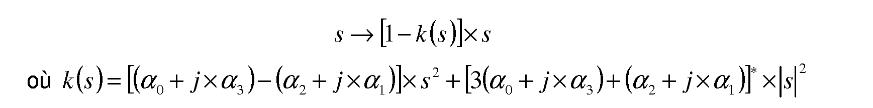 It is then possible to carry out the following correction in complex on the signal s = z / 2 resulting from Hilbert filtering:
Dans le spectre, les deux termes formant la distorsion s x k(s) ont une signification différente : le premier terme représente le cumul de la distorsion harmonique et de l’intermodulation lointaine alors que la deuxième terme représente l’intermodulation proche. Mathématiquement, cela s’écrit ainsi :
 In the spectrum, the two terms forming the distortion sxk (s) have a different meaning: the first term represents the cumulation of the harmonic distortion and the far intermodulation while the second term represents the near intermodulation. Mathematically, this is written as follows:
L’opération ainsi décrite s’effectue après passage en complexe. La séparation des termes « lointains » et « proches » permet de réaliser la seule correction des défauts d’intermodulation « proche ». Une telle correction peut s’effectuer après retour du spectre en bande de base puisque la phase introduite transposition n’affecte pas le terme |s|2. Une telle opération peut aussi s’effectuer après filtrage de la distorsion harmonique et décimation sans craindre de générer des produits harmoniques non désirés dont le repliement est à éviter. Cela n’est bien sûr possible qu’à la condition que la bande du signal soit suffisante faible pour que la distorsion harmonique puisse être filtrée par le plan de fréquence ; pour que cela soit possible après filtrage, il convient également que le plan de fréquence ne déforme pas la phase. The operation thus described is carried out after passing through the complex. The separation of the terms "far" and "close" makes it possible to perform the only correction of "near" intermodulation faults. Such a correction can be made after the return of the baseband spectrum since the phase introduced transposition does not affect the term | s | 2 . Such an operation can also be performed after filtering the harmonic distortion and decimation without fear of generating unwanted harmonic products whose folding is to be avoided. This is of course only possible if the signal band is small enough so that the harmonic distortion can be filtered by the frequency plane; for this to be possible after filtering, it is also appropriate that the frequency plan does not distort the phase.
Dans le cas où le procédé comporte les étapes du troisième exemple, si deux tons à f1 et f2 sont simultanément présents dans la bande, la fonction f(x,y) représentant la distorsion du signal génère à la fois des parasites harmoniques (3 f1 et 3 f2) et des parasites d’intermodulation hors bande (situés à 2 f1 + f2 et 2 f2 + f1) et dans la bande (situés à 2 f1– f2 et 2 f2– f1). In the case where the method comprises the steps of the third example, if two tones at f 1 and f 2 are simultaneously present in the band, the function f (x, y) representing the distortion of the signal generates both harmonic parasites ( 3 f 1 and 3 f 2 ) and out-of-band intermodulation noise (located at 2 f 1 + f 2 and 2 f 2 + f 1 ) and in the band (at 2 f 1 - f 2 and 2 f 2 - f 1 ).
Il est alors possible de poser :
 It is then possible to ask:
Il est alors possible d’obtenir en calculant les différents termes impliqués dans la fonction f(x,y) représentant la distorsion du signal : It is then possible to obtain by calculating the different terms involved in the function f (x, y) representing the distortion of the signal:

Il est alors obtenu une expression pour l’intermodulation et la distorsion harmonique selon laquelle :
An expression is then obtained for intermodulation and harmonic distortion according to which:

Les signaux parasites réels induits par le mécanisme de distorsion cubique considéré sur chacune des six fréquences 2f1– f2, 2f2– f1, 3f1, 2f1 + f2, 2f2 + f1, et 3f2 sont alors respectivement les suivants : The real interference signals induced by the cubic distortion mechanism considered on each of the six frequencies 2f 1 -f 2 , 2f 2 -f 1 , 3f 1 , 2f 1 + f 2 , 2f 2 + f 1 , and 3f 2 are then respectively The following :

• s+1 l’amplitude de la composante obtenue à une première fréquence +f1, • s-1 l’amplitude de la composante obtenue à l’opposé de la première fréquence– f1, • s +1 the amplitude of the component obtained at a first frequency + f 1 , • s -1 the amplitude of the component obtained opposite the first frequency-f 1 ,
• s+2 l’amplitude de la composante obtenue à une deuxième fréquence +f2, • s-2 l’amplitude de la composante obtenue à l’opposé de la deuxième fréquence– f2, S +2 the amplitude of the component obtained at a second frequency + f 2 , • s -2 the amplitude of the component obtained opposite the second frequency f 2 ,
• i+12 l’amplitude de la composante obtenue à une troisième fréquence +2*f1 – f2, • i +12 the amplitude of the component obtained at a third frequency + 2 * f 1 - f 2 ,
• i–12 l’amplitude de la composante obtenue à l’opposé de la troisième fréquence–2*f1 + f2, • i -12 the amplitude of the component obtained opposite to the third frequency-2 * f 1 + f 2,
• i+21 l’amplitude de la composante obtenue à une quatrième fréquence +2*f2 – f1, I +21 the amplitude of the component obtained at a fourth frequency + 2 * f 2 - f 1 ,
• i–21 l’amplitude de la composante obtenue à l’opposé de la quatrième fréquence–2*f2 + f1, • i -21 the amplitude of the component obtained in contrast to the fourth frequency-2 * f 2 + f 1,
• h+1 l’amplitude de la composante obtenue à une cinquième fréquence +3*f1, H +1 the amplitude of the component obtained at a fifth frequency + 3 * f 1 ,
• h-1 l’amplitude de la composante obtenue à l’opposé de la cinquième fréquence– 3*f1, • h -1 the amplitude of the component obtained opposite the fifth frequency-3 * f 1 ,
• h+12 l’amplitude de la composante obtenue à une sixième fréquence +2*f1 + f2, H +12 the amplitude of the component obtained at a sixth frequency + 2 * f 1 + f 2 ,
• h–12 l’amplitude de la composante obtenue à l’opposé de la sixième fréquence–2*f1– f2, • h -12 the amplitude of the component obtained opposite the sixth-frequency 2 * f 1 - f 2,
• h+21 l’amplitude de la composante obtenue à une septième fréquence +2f2 + f1, H +21 the amplitude of the component obtained at a seventh frequency + 2f 2 + f 1 ,
• h–21 l’amplitude de la composante obtenue à l’opposé de la septième fréquence–2f2– f1, • h -21 the amplitude of the component obtained in contrast to the seventh-frequency 2f 2f 1,
• h+2 l’amplitude de la composante obtenue à une huitième fréquence +3*f2, et H +2 the amplitude of the component obtained at an eighth frequency + 3 * f 2 , and
• h-2 l’amplitude de la composante obtenue à l’opposé de la huitième fréquence– 3*f2. • h -2 the amplitude of the component obtained opposite the eighth frequency-3 * f 2 .
Pour chacune des notations introduites, il est à noter que, comme les signaux sont réels, chacune des amplitudes notées avec un indice négatif, c’est-à-dire les grandeurs négatives que sont s-1, i–12, i–21, h-1, h–12, h–21 et h-2, sont les conjuguées des amplitudes
correspondantes notées avec un indice positif, c’est-à-dire les grandeurs positives que sont s+1, i+12, i+21, h+1, h+12, h+21 et h+2. For each of the notations introduced, it should be noted that, as the signals are real, each of the amplitudes noted with a negative index, that is to say the negative quantities that are s -1 , i -12, i -21 , h -1, h -12, h -21 and h -2, are the conjugates of the amplitudes corresponding ones denoted with a positive index, that is to say, the positive quantities that are s + 1 , i + 12, i + 21, h +1, h + 12, h + 21 and h + 2 .
Or, il est connu que sinϕ =ℜ (−j ×e jϕ ) , il est alors obtenu pour l’amplitude de la composante obtenue à la première fréquence +f1 et l’amplitude de la composante obtenue à la deuxième fréquence +f2 les relations suivantes :
 Now, it is known that sinφ = ℜ ( -j × e jφ ) , it is then obtained for the amplitude of the component obtained at the first frequency + f 1 and the amplitude of the component obtained at the second frequency + f 2 the following relationships:
Similairement, la relation sinϕ =ℜ (−j ×e jϕ ) permet d’obtenir pour l’amplitude de la composante obtenue à la troisième fréquence +2*f1– f2 et l’amplitude de la composante obtenue à une quatrième fréquence +2*f2– f1 les relations suivantes : Similarly, the relation sinφ = ℜ ( -j × e jφ ) makes it possible to obtain for the amplitude of the component obtained at the third frequency + 2 * f 1 - f 2 and the amplitude of the component obtained at a fourth frequency + 2 * f 2 - f 1 the following relations:

où la notation « * » en exposant renvoie à l’opération mathématique de conjugaison. where the notation "*" in superscript refers to the mathematical operation of conjugation.
Similairement, la relation sinϕ =ℜ (−j ×e jϕ ) permet d’obtenir des relations pour l’amplitude de la composante obtenue à la cinquième fréquence +3*f1, l’amplitude de la composante obtenue à la sixième fréquence +2*f1 + f2, l’amplitude de la composante obtenue à la septième fréquence +2f2 + f1 et l’amplitude de la composante obtenue à la huitième fréquence +3*f2. Le système suivant donne le détail de chacune des relations mathématiques précédentes : Similarly, the relation sinφ = ℜ (-j × e jφ ) makes it possible to obtain relations for the amplitude of the component obtained at the fifth frequency + 3 * f 1 , the amplitude of the component obtained at the sixth frequency + 2 * f 1 + f 2 , the amplitude of the component obtained at the seventh frequency + 2f 2 + f 1 and the amplitude of the component obtained at the eighth frequency + 3 * f 2 . The following system gives the detail of each of the previous mathematical relationships:

Par identification des différents termes, il est obtenu le système d’équations suivant :
By identification of the different terms, the following system of equations is obtained:

A l’analyse du système d’équations obtenu, il apparaît qu’il s’agit d’un système d’équations avec une forte redondance. Dès lors, il est possible de considérer un système d’équations dit « moyen » en utilisant des opérations de moyennages, notamment par emploi de moyenne arithmétique. In the analysis of the system of equations obtained, it appears that it is a system of equations with a strong redundancy. Therefore, it is possible to consider a system of so-called "average" equations by using averaging operations, in particular by using arithmetic mean.
Selon un premier exemple, il est obtenu le système d’équations dit « moyen » suivant : According to a first example, the following equations system is obtained:
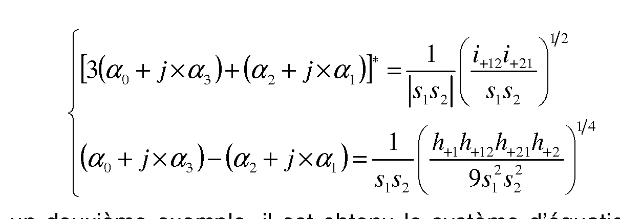
Selon un deuxième exemple, il est obtenu le système d’équations dit « moyen » suivant : According to a second example, the following equations system is obtained:

Le procédé de correction précédemment décrit s’applique également pour corriger des intermodulations d’ordre différent. The previously described correction method also applies to correct intermodulation of different order.
Une telle extension s’obtient en utilisant des polynômes d’ordres supérieurs en |s|2, c’est-à-dire des termes de correction de la formeSuch an extension is obtained by using polynomials of higher order in | s | 2 , i.e., shape correction terms

En supposant que s = s1 + s 2 où s1 et s2 sont deux signaux aux fréquences f1 et f2, il est alors obtenu l’expression mathématique suivante:
 Assuming that s = s 1 + s 2 where s 1 and s 2 are two signals at frequencies f 1 and f 2 , then the following mathematical expression is obtained:
Il en résulte que :
 où les coefficients sont les coefficients du binôme.It follows that : where the coefficients are the coefficients of the binomial.
Or, en écrivant le premier signal s1 et le deuxième signal s2 sous forme complexe, c’est-à-dire, si s1 crit: However, by writing the first signal s 1 and the second signal s 2 in complex form, that is to say, if s 1 crit:

D’où il résulte que : k = 0 From which it follows that: k = 0

Une telle formule s’applique notamment pour l’intermodulation d’ordre 5. Dans un tel cas, l’entier n est égal à 2. Ceci s’écrit mathématiquement comme :
 Such a formula applies in particular for the intermodulation of order 5. In such a case, the integer n is equal to 2. This is written mathematically as:
De manière plus explicite, l’expression précédente s’écrit :
 More explicitly, the previous expression is written:
Or, il est rappelé que dans ce cas, nous avons However, it is recalled that in this case, we have

Ainsi, il est obtenu le résultat suivant : Thus, it is obtained the following result:

Ainsi, à partir des mesures d’intermodulation, il est obtenu en notant respectivement
 les produits d’intermodulation à (p+1) x f1 + p x f2 et (p+1) x f2 + p x f1 le système d’équations suivant:
 So, from the intermodulation measurements, it is obtained by noting respectively intermodulation products at (p + 1) xf 1 + pxf 2 and (p + 1) xf 2 + pxf 1 the following system of equations:
Il est possible de démontrer qu’un tel système redondant a une solution et qu’il est favorable de considérer une solution moyenne comme la solution qui suit, à savoir :
 It is possible to demonstrate that such a redundant system has a solution and that it is favorable to consider an average solution as the following solution, namely:
Ceci rouve u’il est ossible de corri er l’intermodulation d’ordre 5.
 k 0 q 0 This makes it easy to correct the 5-way intermodulation. k 0 q 0
s’applique également pour l’intermodulation d’ordre 7. Dans un tel cas, l’entier n est égal à 3. Ceci s’écrit mathématiquement comme : also applies to order 7 intermodulation. In such a case, the integer n is equal to 3. This is written mathematically as:

De manière plus explicite, l’expression précédente s’écrit : More explicitly, the previous expression is written:

Il est ainsi obtenu l’expression qui suit : It is thus obtained the following expression:


Ainsi, à partir des mesures d’intermodulation, il est obtenu en notant respectivement i (2p+1) Thus, from the intermodulation measurements, it is obtained by noting respectively i (2p + 1)
12 et i (2p+1) 1 2 and i (2p + 1)
21 les produits d’intermodulation à (p+1) x f1 + p x f2 et (p+1) x f2 + p x f1 le système d’équations suivant: 2 1 intermodulation products at (p + 1) xf 1 + pxf 2 and (p + 1) xf 2 + pxf 1 the following system of equations:

Il est possible de démontrer qu’un tel système redondant a une solution et qu’il est favorable de considérer une solution moyenne comme la solution qui suit, à savoir : It is possible to demonstrate that such a redundant system has a solution and that it is favorable to consider an average solution as the following solution, namely:


Ceci prouve qu’il est possible de corriger l’intermodulation d’ordre 7. This proves that it is possible to correct the intermodulation of order 7.
Il est possible de démontrer que la démarche suivie pour l’intermodulation d’ordre 5 et l’intermodulation d’ordre 7 s’applique aussi pour des intermodulations d’ordres supérieurs. It is possible to demonstrate that the approach followed for the intermodulation of order 5 and the intermodulation of order 7 also applies for intermodulations of higher order.
La prise en compte de termes jusqu’à l’ordre 2n+1 s’effectue de façon similaire ; elle est laborieuse mais ne comporte pas de difficulté de principe. Comme pour n = 1, 2 ou 3 on obtient un système triangulaire qui permet de calculer α(n-1) en premier puis successivement α (n-2), α (n-3),…, jusqu’à α (0). The taking into account of terms up to the order 2n + 1 is done in a similar way; it is laborious but does not involve a difficulty of principle. As for n = 1, 2 or 3 one obtains a triangular system which makes it possible to calculate α (n-1) first then successively α (n-2) , α (n-3) , ..., until α (0 ) .
Dans ce qui suit, il est étudié la dépendance par rapport à la fréquence instantanée. In what follows, the dependence on the instantaneous frequency is studied.
Comme expliqué précédemment, la correction à retrancher au signal s’écrit sous la forme mathématique suivante :
 As previously explained, the correction to be subtracted from the signal is written in the following mathematical form:
Ce résultat, obtenu sous l’hypothèse que la bande instantanée est faible, peut être conservé dans sa forme dans une bande plus large sous la condition que les coefficients du polynôme P dépendent de la fréquence instantanée. Pour cela, il est considéré une dépendance linéaire :
 This result, obtained under the assumption that the instantaneous band is weak, can be preserved in its form in a wider band under the condition that the coefficients of the polynomial P depend on the instantaneous frequency. For this, it is considered a linear dependence:
Or la fréquence instantanée est, à un facteur multiplicatif 2π près, égale à la partie imaginaire de la dérivée logarithmi ue du si nal :
 Now the instantaneous frequency is, to a multiplicative factor 2π, equal to the imaginary part of the logarithm derivative of the si nal:
Ainsi, l’équation relative au produit k (s ) × s s’écrit mathématiquement comme :
 Thus, the product equation k (s) × s can be written mathematically as:
Dans la relation précédente, supposée être calculée dans le domaine du temps discret (c’est-à-dire sur signal échantillonné), s’ représente les valeurs de la dérivée du signal complexe aux instants d’échantillonnage. Il s’agit donc du filtrage du signal s par le filtre dérivateur, qui correspond en fait à l’échantillonnage de la dérivée du filtre interpolateur de réponse temporelle en un sinus cardinal. De ce fait, la relation précédente s’exprime comme :
In the previous relationship, assumed to be computed in the discrete time domain (i.e., sampled signal), s' represents the values of the derivative of the complex signal at the sampling instants. It is therefore the filtering of the signal s by the derivative filter, which in fact corresponds to the sampling of the derivative of the temporal response interpolator filter in a cardinal sinus. As a result, the previous relationship is expressed as:

Il est à remarquer que la forme de k(s) (déterminée par le terme entre [ ]) ne dépend pas de la fréquence instantanée fi. Cela signifie que la forme de k(s) est indépendante de la position dans la chaîne de démodulation. It should be noted that the form of k (s) (determined by the term between []) does not depend on the instantaneous frequency f i . This means that the form of k (s) is independent of the position in the demodulation chain.
Par contre, la valeur des coefficients des polynômes P et Q dépendent de la fréquence instantanée fi de la porteuse du signal, la démodulation par une fréquence fOL revenant à transférer le terme Q(|s|2) x fOL sur P(|s|2). Bien entendu, le filtre hD, qui ne dépend pas du signal, ne dépend pas de la valeur de la fréquence instantanée fi. On the other hand, the value of the coefficients of the polynomials P and Q depends on the instantaneous frequency f i of the carrier of the signal, the demodulation by a frequency f OL returning to transfer the term Q (| s | 2 ) xf OL on P (| s | 2 ). Of course, the filter h D , which does not depend on the signal, does not depend on the value of the instantaneous frequency f i .
Il est donc constaté que, malgré la dépendance par rapport à la fréquence instantanée, la forme de la correction reste invariante dans la transposition du spectre (même si les coefficients varient) si bien qu’il reste possible d’effectuer la correction après retour en bande de base et décimation, ce qui facilite grandement les opérations. It is therefore found that, despite the dependence on the instantaneous frequency, the shape of the correction remains invariant in the transposition of the spectrum (even if the coefficients vary) so that it remains possible to perform the correction after returning to baseband and decimation, which greatly facilitates operations.
Par exemple, la connaissance des coefficients des deux polynômes P et Q s’obtient par calibrage. Pour cela, il convient d’effectuer deux mesures de calibrage sur deux fréquences instantanées différentes f1 et f2. Pour les deux mesures, il est obtenu par la méthode précédente deux polynômes P1 et P2 a priori différents :
 For example, the knowledge of the coefficients of the two polynomials P and Q is obtained by calibration. For this, it is necessary to perform two calibration measurements on two different instantaneous frequencies f 1 and f 2 . For the two measurements, it is obtained by the preceding method two polynomials P 1 and P 2 a priori different:
ce qui permet d’obtenir les valeurs de α et de β en utilisant le système : which makes it possible to obtain the values of α and β using the system:


Il en résulte alors que la fréquence instantanée vaut : As a result, the instantaneous frequency is:

C’est-à-dire :
 That is to say :
Comme la fréquence instantanée fi varie avec le temps, il est considéré la valeur moyenne de la fréquence instantanée fi pondérée par la puissance du signal pour favoriser les instants où le signal présente l’amplitude la plus grande. En remarquant que la valeur moyenne de cos(φA - φB) est nulle étant donné que, par hypothèse, la fréquence fA est différente de la fréquence fB, il est obtenu la formule suivante pour la valeur moyenne de la fréquence instantanée fi, valeur moyenne notée < fi >: Since the instantaneous frequency f i varies with time, the average value of the instantaneous frequency f i, weighted by the signal power, is considered to favor the moments when the signal has the greatest amplitude. Noting that the average value of cos (φ A - φ B ) is zero since, by hypothesis, the frequency f A is different from the frequency f B , the following formula is obtained for the mean value of the instantaneous frequency f i , mean value noted <f i >:

Dans le cas où l’amplitude des deux signaux à la fréquence fA et à la fréquence fB sont les mêmes, on a alors aA = aB, ce qui résulte en < fi > = (fA + fB) / 2. In the case where the amplitude of the two signals at the frequency f A and the frequency f B are the same, then we have A = a B , which results in <f i > = (f A + f B ) / 2.
Les amplitudes de chacune des composante peuvent être calculés par transformée de Fourier rapide ou, compte tenu du faible nombre de points à calculer, par simple transformation de Fourier discrète. The amplitudes of each of the components can be calculated by fast Fourier transform or, given the small number of points to be calculated, by simple discrete Fourier transformation.
Pour des questions de simplicité, il est généré des fréquences sur un pas de transformée de Fourier rapide le plus large possible. Le nombre de points dépend de l’ordre maximum à corriger. Pour une correction jusqu’à l’ordre 2*N+1, le nombre total nFFT de composantes à mesurer est de 2*(N+1). Il est souhaitable que les fréquences des deux calibrages soient le plus éloignées l’une de l’autre tout en conservant un nombre minimum de points de transformée de Fourier rapide. Le cas extrême consiste à prendre :
• nFFT = 2(N+1) d’une part, et For simplicity, it generates frequencies on a fast Fourier transform step as wide as possible. The number of points depends on the maximum order to be corrected. For a correction up to the order 2 * N + 1, the total number n FFT of components to be measured is 2 * (N + 1). It is desirable that the frequencies of the two calibrations be farthest from each other while maintaining a minimum number of fast Fourier transform points. The extreme case is to take: • n FFT = 2 (N + 1) on the one hand, and
• fA = ±fECH/2 et fB = ±N/(N+1) x fECH/2 d’autre part • f A = ± f ECH / 2 and f B = ± N / (N + 1) xf ECH / 2 on the other hand
En variante, il est également possible de rapprocher les fréquences pour être moins sensible à la réponse du filtre de décimation qui atténue inévitablement les bords de la bande d’échantillonnage. Ainsi, lorsque seuls les termes d’ordre 3 sont à corriger, il est possible de considérer une transformée de Fourier rapide à 4 points dont le calcul est extrêmement simple avec fA = ±fECH/4 et fB = 0. Dans ce cas les produits d’intermodulation sont situés à ±fECH/2 et–fA. Simulations Alternatively, it is also possible to approximate the frequencies to be less sensitive to the response of the decimation filter which inevitably attenuates the edges of the sampling band. Thus, when only the terms of order 3 are to be corrected, it is possible to consider a 4-point fast Fourier transform whose calculation is extremely simple with f A = ± f ECH / 4 and f B = 0. the intermodulation products are located at ± ECH / 2 and -f A. simulations
Des simulations sont représentées aux figures 3 à 10. Simulations are shown in Figures 3 to 10.
Les simulations qui suivent ont été réalisées à partir de séries de mesures 2 tons d’amplitudes respectives voisines de–6 dBFS (DéciBell à pleine échelle) chacune. De telles mesures ont été effectuées sur un convertisseur analogique-numérique autour de trois points de fonctionnement f0 différents voisins des fréquences 2,1*fECH, 2.2*fECH et 2.3 fECH. Les deux tons séparés de fECH/256 étaient situés respectivement à fA = f0– fECH/512 et fB = f0 + fECH/512 avec, suivant les cas : The simulations that follow were made from series of 2-ton measurements of respective amplitudes close to -6 dBFS (decibell at full scale) each. Such measurements have been made on an analog-to-digital converter around three operating points f 0 different from the frequencies 2.1 * f ECH , 2.2 * f ECH and 2.3 f ECH . The two separate tones of f ECH / 256 were located respectively at f A = f 0 - f ECH / 512 and f B = f 0 + f ECH / 512 with, as appropriate:
• f0 = ( 2 + 103/1024 ) x fECH , premier point voisin de 2.1 fECH, • f 0 = (2 + 103/1024) xf ECH , first point close to 2.1 f ECH ,
• f0 = ( 2 + 205/1024 ) x fECH , second point voisin de 2.2 fECH, et • f 0 = (2 + 205/1024) xf ECH , second point close to 2.2 f ECH , and
• f0 = ( 2 + 307/1024 ) x fECH , troisième point voisin de 2.3 fECH • f 0 = (2 + 307/1024) xf ECH , third point close to 2.3 f ECH
Pour chaque point de fonctionnement, quatre mesures différentes ont été effectuées correspondant à quatre conditions de phase différentes entre signaux et entre signal et horloge. For each operating point, four different measurements were made corresponding to four different phase conditions between signals and between signal and clock.
Une mesure du premier point de fonctionnement et une mesure du troisième point de calibrage sont utilisées comme mesures de calibrage pour un traitement visant à corriger les défauts jusqu’à l’ordre 5. A measurement of the first operating point and a measurement of the third calibration point are used as calibration measurements for treatment to correct defects up to order 5.
Plusieurs simulations du traitement calibrage/correction ont été effectuées à partir de ces mesures. Several simulations of calibration / correction processing were performed from these measurements.
Pour les cas des figures 3 à 5, il a été effectué un traitement calibrage/correction à pleine vitesse après filtrage de Hilbert sans translation du spectre ni décimation. Pour chaque cas, les courbes représentent le maximum de l’amplitude obtenue sur les quatre mesures. Chacune des figures 3 à 5 illustrent respectivement la variation de l’amplitude en fonction de la fréquence pour les trois points de fonctionnement différents. For the cases of FIGS. 3 to 5, calibration / correction processing was performed at full speed after Hilbert filtering without spectrum translation or decimation. For each case, the curves represent the maximum of the amplitude obtained on the four measurements. Each of FIGS. 3 to 5 respectively illustrate the variation of the amplitude as a function of the frequency for the three different operating points.
Pour les cas des figures 6 à 8, il a été effectué un traitement calibrage/correction à pleine vitesse après filtrage de Hilbert puis translation de–205/1024 fECH mais sans décimation. Pour chaque cas, les courbes représentent le maximum de l’amplitude
obtenue sur les quatre mesures. Chacune des figures 6 à 8 illustrent respectivement la variation de l’amplitude en fonction de la fréquence pour les trois points de fonctionnement différents. For the cases of FIGS. 6 to 8, a calibration / correction processing was carried out at full speed after Hilbert filtering and translation of 205/21024 ECH but without decimation. For each case, the curves represent the maximum of the amplitude obtained on the four measurements. Each of FIGS. 6 to 8 respectively illustrate the variation of amplitude as a function of frequency for the three different operating points.
Pour les cas des figures 9 à 11, il a été effectué un traitement calibrage/correction à pleine vitesse après filtrage de Hilbert puis translation de–205/1024 fECH avec décimation par 4. Pour chaque cas, les courbes représentent le maximum de l’amplitude obtenue sur les quatre mesures. Chacune des figures 9 à 11 illustrent respectivement la variation de l’amplitude en fonction de la fréquence pour les trois points de fonctionnement différents. For the cases of FIGS. 9 to 11, a calibration / correction process was carried out at full speed after Hilbert filtering and translation of-205/1024 f ECH with decimation by 4. For each case, the curves represent the maximum of 1 amplitude obtained on the four measurements. Each of FIGS. 9 to 11 respectively illustrate the variation of amplitude as a function of frequency for the three different operating points.
Pour les simulations, les filtres de Hilbert et de décimation utilisés sont des filtres idéaux. For simulations, the Hilbert and decimation filters used are ideal filters.
Ainsi, dans le cas d’un signal répétitif, donc mesuré sur une durée finie multiple de sa période (1024 points en l’occurrence), il y a lieu de replier le filtre de dérivation dont la durée est infinie ; si N est la durée totale. Cela s’exprime mathématiquement comme :
 Thus, in the case of a repetitive signal, thus measured over a multiple finite duration of its period (1024 points in this case), it is necessary to fold the derivation filter whose duration is infinite; if N is the total duration. This is expressed mathematically as:
C’est-à-dire, en utilisant que l’expression précédente devient: That is, using that the preceding expression becomes:


D’où :
 From where :
Conclusion Conclusion
Il est proposé un procédé de correction des défauts d’intermodulation d’une chaîne de réception comportant un convertisseur analogique-numérique et une chaîne de réception mettant en œuvre un tel procédé. Le procédé permet de trouver un mécanisme de compensation travaillant sur signaux démodulés, filtrés, décimés et ne compensant que l’intermodulation sans introduire de distorsion harmonique non désirée.
Ainsi, le procédé de correction des défauts d’intermodulation introduits par un circuit de conversion permet, avec une mise en œuvre aisée, de diminuer les défauts d’intermodulation sans générer de la distorsion harmonique non désirée.
There is provided a method for correcting the intermodulation faults of a reception channel comprising an analog-to-digital converter and a reception channel implementing such a method. The method makes it possible to find a compensation mechanism working on demodulated, filtered, decimated signals and only compensating for intermodulation without introducing unwanted harmonic distortion. Thus, the method for correcting intermodulation faults introduced by a conversion circuit makes it possible, with an easy implementation, to reduce the intermodulation faults without generating unwanted harmonic distortion.
Claims
REVENDICATIONS 1.- Procédé de correction des défauts d’intermodulation introduits par un circuit de conversion (14) adapté à convertir un signal analogique d’entrée en un signal numérique de sortie, le procédé comportant les étapes de : 1. A method for correcting intermodulation faults introduced by a conversion circuit (14) adapted to convert an input analog signal into a digital output signal, the method comprising the steps of:
- fourniture du signal numérique de sortie, - supply of the digital output signal,
- génération d’une fonction de correction, la fonction de correction étant une fonction complexe du signal numérique de sortie, et generating a correction function, the correction function being a complex function of the digital output signal, and
- correction du signal numérique de sortie à l’aide de la fonction de correction, pour obtenir un signal numérique de sortie corrigé. 2.- Procédé selon la revendication 1, dans lequel l’étape de génération de la fonction de correction comporte la mise en œuvre d’au moins un ensemble d’étapes, chaque ensemble d’étapes étant choisi dans le groupe constitué d’un premier ensemble d’étapes, d’un deuxième ensemble d’étapes et d’un troisième ensemble d’étapes, - correction of the digital output signal using the correction function, to obtain a corrected output digital signal. The method of claim 1, wherein the step of generating the correction function comprises implementing at least one set of steps, each set of steps being selected from the group consisting of first set of steps, a second set of steps and a third set of steps,
le premier ensemble d’étapes comprenant les étapes de : the first set of steps including the steps of:
- calcul d’une première fonction polynômiale du carrée du module du signal numérique de sortie, pour obtenir un premier terme final, calculating a first polynomial function of the square of the module of the digital output signal, to obtain a first final term,
- calcul d’une deuxième fonction polynômiale du carrée du module du signal numérique de sortie selon une représentation complexe, pour obtenir un deuxième terme intermédiaire, calculating a second polynomial function of the square of the digital output signal module according to a complex representation, to obtain a second intermediate term,
- application d’un filtre sur le signal numérique de sortie pour obtenir un signal filtré, - applying a filter on the digital output signal to obtain a filtered signal,
- calcul du produit du deuxième terme intermédiaire par le produit du complexe conjugué du signal numérique de sortie par le signal filtré, pour obtenir un deuxième terme final, et calculating the product of the second intermediate term by the product of the conjugate complex of the digital output signal by the filtered signal, to obtain a second final term, and
- calcul de la somme du premier terme final et du deuxième terme final, pour obtenir la fonction de correction, calculating the sum of the first final term and the second final term, to obtain the correction function,
le deuxième ensemble d’étapes comprenant les étapes de : the second set of steps including the steps of:
- l’application d’au moins une opération au signal numérique de sortie, pour obtenir un signal de calcul, l’étape de correction comportant l’application de la fonction de correction au signal de calcul, et the application of at least one operation to the digital output signal, in order to obtain a calculation signal, the correction step comprising the application of the correction function to the calculation signal, and
le troisième ensemble d’étapes comprenant les étapes de : the third set of steps including the steps of:
- application d’un signal de calibration au circuit de conversion (14), par exemple un signal à deux fréquences distinctes,
- mesure du signal obtenue en sortie du circuit de conversion (14), pour obtenir un signal mesuré et applying a calibration signal to the conversion circuit (14), for example a signal with two distinct frequencies, measuring the signal obtained at the output of the conversion circuit (14), in order to obtain a measured signal and
- analyse des composantes spectrales du signal mesuré 3.- Procédé selon la revendication 1 ou 2, le signal numérique de sortie corrigé est égal à la différence entre le signal numérique de sortie et le produit du signal numérique de sortie par la fonction de correction. 4.- Procédé selon l’une quelconque des revendications 1 à 3, dans lequel, l’étape de génération comporte les étapes de : - Analysis of the spectral components of the measured signal 3. - Method according to claim 1 or 2, the corrected output digital signal is equal to the difference between the digital output signal and the product of the digital output signal by the correction function. 4. A process according to any one of claims 1 to 3, wherein, the generating step comprises the steps of:
- calcul d’une première fonction polynômiale du carrée du module du signal numérique de sortie, pour obtenir un premier terme final, calculating a first polynomial function of the square of the module of the digital output signal, to obtain a first final term,
- calcul d’une deuxième fonction polynômiale du carrée du module du signal numérique de sortie selon une représentation complexe, pour obtenir un deuxième terme intermédiaire, calculating a second polynomial function of the square of the digital output signal module according to a complex representation, to obtain a second intermediate term,
- application d’un filtre sur le signal numérique de sortie pour obtenir un signal filtré, - applying a filter on the digital output signal to obtain a filtered signal,
- calcul du produit du deuxième terme intermédiaire par le produit du complexe conjugué du signal numérique de sortie par le signal filtré, pour obtenir un deuxième terme final, et calculating the product of the second intermediate term by the product of the conjugate complex of the digital output signal by the filtered signal, to obtain a second final term, and
- calcul de la somme du premier terme final et du deuxième terme final, pour obtenir la fonction de correction. 5.- Procédé selon la revendication 4, dans lequel, le filtre appliqué à l’étape d’application d’un filtre restitue la dérivée du signal numérique de sortie. 6.- Procédé selon l’une quelconque des revendications 1 à 5, dans lequel l’étape de génération comporte l’application d’au moins une opération au signal numérique de sortie, pour obtenir un signal de calcul, l’étape de correction comportant l’application de la fonction de correction au signal de calcul. 7.- Procédé selon la revendication 6, dans lequel au moins une opération est choisie dans le groupe constitué de: calculating the sum of the first final term and the second final term, to obtain the correction function. 5. The method of claim 4, wherein, the filter applied to the filter application step restores the derivative of the digital output signal. 6. A method according to any one of claims 1 to 5, wherein the generating step comprises the application of at least one operation to the digital output signal, to obtain a calculation signal, the correction step including the application of the correction function to the calculation signal. The method of claim 6, wherein at least one operation is selected from the group consisting of:
- un filtrage de Hilbert du signal numérique de sortie, a Hilbert filtering of the digital output signal,
- une démodulation numérique du signal numérique de sortie, a digital demodulation of the digital output signal,
- un filtre à phase linéaire, et
- une décimation. 8.- Procédé selon l’une quelconque des revendications 1 à 7, dans lequel l’étape de génération comporte les étapes de : a linear phase filter, and - a decimation. The method of any one of claims 1 to 7, wherein the generating step comprises the steps of:
- application d’un signal de calibration au circuit de conversion (14), par exemple un signal à deux fréquences distinctes, applying a calibration signal to the conversion circuit (14), for example a signal with two distinct frequencies,
- mesure du signal obtenue en sortie du circuit de conversion (14), pour obtenir un signal mesuré et measuring the signal obtained at the output of the conversion circuit (14), in order to obtain a measured signal and
- analyse des composantes spectrales du signal mesuré. 9.- Produit programme d’ordinateur comportant un support lisible d’informations, sur lequel est mémorisé un programme d’ordinateur comprenant des instructions de programme, le programme d’ordinateur étant chargeable sur une unité de traitement de données et adapté pour entraîner la mise en œuvre d’un procédé selon l’une quelconque des revendications 1 à 8 lorsque le programme d’ordinateur est mis en œuvre sur l’unité de traitement des données. 10.- Appareil électronique (10) comportant : - analysis of the spectral components of the measured signal. 9. A computer program product comprising a readable information medium, on which is stored a computer program including program instructions, the computer program being loadable on a data processing unit and adapted to train the computer. implementing a method according to any one of claims 1 to 8 when the computer program is implemented on the data processing unit. 10. Electronic device (10) comprising:
- un récepteur (12) d’un signal analogique d’entrée, a receiver (12) of an input analog signal,
- un circuit de conversion (14) adapté à convertir le signal analogique d’entrée en un signal numérique de sortie en introduisant des défauts d’intermodulation, et - un correcteur (16) adapté à générer d’une fonction de correction des défauts d’intermodulation, la fonction de correction étant une fonction complexe du signal numérique de sortie, et à corriger le signal numérique de sortie à l’aide de la fonction de correction, pour obtenir un signal numérique de sortie corrigé. 11.- Appareil selon la revendication 10, dans lequel le correcteur (16) est un circuit logique programmable.
a conversion circuit adapted to convert the input analog signal into a digital output signal by introducing intermodulation faults; and a corrector (16) adapted to generate a defect correction function. intermodulation, the correction function being a complex function of the digital output signal, and correcting the digital output signal using the correction function, to obtain a corrected output digital signal. 11. Apparatus according to claim 10, wherein the corrector (16) is a programmable logic circuit.
Priority Applications (2)
| Application Number | Priority Date | Filing Date | Title |
|---|---|---|---|
| ES15821061T ES2947307T3 (en) | 2014-12-19 | 2015-12-18 | Intermodulation error correction procedure of a conversion circuit |
| EP15821061.7A EP3235137B1 (en) | 2014-12-19 | 2015-12-18 | Method for correcting intermodulation errors of a conversion circuit |
Applications Claiming Priority (2)
| Application Number | Priority Date | Filing Date | Title |
|---|---|---|---|
| FR1402939A FR3030946B1 (en) | 2014-12-19 | 2014-12-19 | METHOD FOR CORRECTING INTERMODULATION DEFECTS IN A CONVERSION CIRCUIT |
| FR1402939 | 2014-12-19 |
Publications (1)
| Publication Number | Publication Date |
|---|---|
| WO2016097395A1 true WO2016097395A1 (en) | 2016-06-23 |
Family
ID=53514207
Family Applications (1)
| Application Number | Title | Priority Date | Filing Date |
|---|---|---|---|
| PCT/EP2015/080693 WO2016097395A1 (en) | 2014-12-19 | 2015-12-18 | Method for correcting intermodulation errors of a conversion circuit |
Country Status (4)
| Country | Link |
|---|---|
| EP (1) | EP3235137B1 (en) |
| ES (1) | ES2947307T3 (en) |
| FR (1) | FR3030946B1 (en) |
| WO (1) | WO2016097395A1 (en) |
Citations (2)
| Publication number | Priority date | Publication date | Assignee | Title |
|---|---|---|---|---|
| US5237332A (en) * | 1992-02-25 | 1993-08-17 | Hughes Aircraft Company | Receiver distortion correction circuit and method |
| US20050219089A1 (en) * | 2004-03-25 | 2005-10-06 | Optichron, Inc. | Digital linearizing system |
Family Cites Families (1)
| Publication number | Priority date | Publication date | Assignee | Title |
|---|---|---|---|---|
| WO2010069365A1 (en) * | 2008-12-16 | 2010-06-24 | Signal Processing Devices Sweden Ab | Methods and apparatuses for estimation and compensation of nonlinearity errors |
-
2014
- 2014-12-19 FR FR1402939A patent/FR3030946B1/en active Active
-
2015
- 2015-12-18 ES ES15821061T patent/ES2947307T3/en active Active
- 2015-12-18 WO PCT/EP2015/080693 patent/WO2016097395A1/en active Application Filing
- 2015-12-18 EP EP15821061.7A patent/EP3235137B1/en active Active
Patent Citations (2)
| Publication number | Priority date | Publication date | Assignee | Title |
|---|---|---|---|---|
| US5237332A (en) * | 1992-02-25 | 1993-08-17 | Hughes Aircraft Company | Receiver distortion correction circuit and method |
| US20050219089A1 (en) * | 2004-03-25 | 2005-10-06 | Optichron, Inc. | Digital linearizing system |
Non-Patent Citations (1)
| Title |
|---|
| REBEIZ ERIC ET AL: "Suppressing RF front-end nonlinearities in wideband spectrum sensing", 8TH INTERNATIONAL CONFERENCE ON COGNITIVE RADIO ORIENTED WIRELESS NETWORKS, ICST - THE INSTITUTE FOR COMPUTER SCIENCES, SOCIAL INFORMATICS AND TELECOMMUNICATIONS ENGINEERING, 8 July 2013 (2013-07-08), pages 87 - 92, XP032510473 * |
Also Published As
| Publication number | Publication date |
|---|---|
| EP3235137B1 (en) | 2023-04-12 |
| ES2947307T3 (en) | 2023-08-04 |
| FR3030946A1 (en) | 2016-06-24 |
| FR3030946B1 (en) | 2019-09-13 |
| EP3235137A1 (en) | 2017-10-25 |
Similar Documents
| Publication | Publication Date | Title |
|---|---|---|
| US20140079098A1 (en) | Multi-stage charge re-use analog circuits | |
| US20080231488A1 (en) | Bandwidth multiplication for a test and measurement instrument using non-periodic functions for mixing | |
| EP3304107B1 (en) | Reflectometry method and device for diagnosing cables in use | |
| WO2019215098A1 (en) | Measurement method and electronic measuring unit using an inductive proximity sensor linked to a cable | |
| EP3235137B1 (en) | Method for correcting intermodulation errors of a conversion circuit | |
| FR3050849B1 (en) | METHOD AND DEVICE FOR REDUCING NOISE IN A MODULE SIGNAL | |
| CN110768661B (en) | Phase-locked amplifier based on neural network | |
| EP2978127B1 (en) | Method for digitally compensating variations, based on the temperature, of an electrical variable of an onboard spatial radio frequency telecommunications device | |
| EP1782536B1 (en) | Method of generating a digital signal that is representative of match errors in an analogue-to-digital conversion system with time interleaving, and an analogue-to-digital converter with time interleaving using same | |
| CN108322217B (en) | Correction circuit and correction method for time-interleaved analog-to-digital converter | |
| FR2914515A1 (en) | CALIBRATION IN A RADIO FREQUENCY TRANSMIT MODULE | |
| FR2778259A1 (en) | CIRCUIT OF ARITHMETIC COMBINATIONS OF AN ANALOGUE SIGNAL TO A VALUE IN NUMERICAL FORM AND PROCESS AS WELL AS A DEVICE FOR DETERMINING AN ANGLE | |
| EP0928062B1 (en) | Linearity correction method and circuit for power amplifier and amplifier with such a circuit | |
| EP2028810B1 (en) | Correction of distortions in a transmission chain | |
| FR3104859A1 (en) | SIGNAL DECOUPLING PROCESS IN TRANSMISSION / RECEPTION SYSTEMS | |
| EP2091149A1 (en) | Method and device for downconverting the sampling frequency of a digital signal. | |
| Zhao et al. | Model calibration of non-ideal lowpass filter in modulated wideband converter for compressive sampling | |
| D’Arco et al. | Digital circuit for the arbitrary selection of sample rate in digital storage oscilloscopes | |
| EP0333566B1 (en) | Method and devices for the translation along the frequency axis of the modulus of the transfer function of a filter | |
| EP3895041A1 (en) | Method and system for processing a signal in order to extract a useful signal from a disturbed signal | |
| WO2023242554A1 (en) | Analogue to digital converter | |
| GB2541379A (en) | Method and system for improving spurious free dynamic range of signal processing systems | |
| EP2104238B1 (en) | Apparatus for modulating an analog signal in a frequency wideband with a digital modulation signal | |
| CN103326722B (en) | A kind of adaptive sample value estimating circuit and method | |
| FR2536541A1 (en) | Simplified spectral analysis system using phases |
Legal Events
| Date | Code | Title | Description |
|---|---|---|---|
| 121 | Ep: the epo has been informed by wipo that ep was designated in this application |
Ref document number: 15821061 Country of ref document: EP Kind code of ref document: A1 |
|
| NENP | Non-entry into the national phase |
Ref country code: DE |
|
| REEP | Request for entry into the european phase |
Ref document number: 2015821061 Country of ref document: EP |