WO2016163348A1 - Injector - Google Patents
Injector Download PDFInfo
- Publication number
- WO2016163348A1 WO2016163348A1 PCT/JP2016/061087 JP2016061087W WO2016163348A1 WO 2016163348 A1 WO2016163348 A1 WO 2016163348A1 JP 2016061087 W JP2016061087 W JP 2016061087W WO 2016163348 A1 WO2016163348 A1 WO 2016163348A1
- Authority
- WO
- WIPO (PCT)
- Prior art keywords
- syringe
- piston
- plunger
- hole
- end side
- Prior art date
Links
Images


Classifications
-
- A—HUMAN NECESSITIES
- A61—MEDICAL OR VETERINARY SCIENCE; HYGIENE
- A61M—DEVICES FOR INTRODUCING MEDIA INTO, OR ONTO, THE BODY; DEVICES FOR TRANSDUCING BODY MEDIA OR FOR TAKING MEDIA FROM THE BODY; DEVICES FOR PRODUCING OR ENDING SLEEP OR STUPOR
- A61M5/00—Devices for bringing media into the body in a subcutaneous, intra-vascular or intramuscular way; Accessories therefor, e.g. filling or cleaning devices, arm-rests
- A61M5/178—Syringes
- A61M5/31—Details
- A61M5/315—Pistons; Piston-rods; Guiding, blocking or restricting the movement of the rod or piston; Appliances on the rod for facilitating dosing ; Dosing mechanisms
-
- A—HUMAN NECESSITIES
- A61—MEDICAL OR VETERINARY SCIENCE; HYGIENE
- A61M—DEVICES FOR INTRODUCING MEDIA INTO, OR ONTO, THE BODY; DEVICES FOR TRANSDUCING BODY MEDIA OR FOR TAKING MEDIA FROM THE BODY; DEVICES FOR PRODUCING OR ENDING SLEEP OR STUPOR
- A61M5/00—Devices for bringing media into the body in a subcutaneous, intra-vascular or intramuscular way; Accessories therefor, e.g. filling or cleaning devices, arm-rests
- A61M5/178—Syringes
- A61M5/20—Automatic syringes, e.g. with automatically actuated piston rod, with automatic needle injection, filling automatically
- A61M5/2046—Media being expelled from injector by gas generation, e.g. explosive charge
-
- A—HUMAN NECESSITIES
- A61—MEDICAL OR VETERINARY SCIENCE; HYGIENE
- A61M—DEVICES FOR INTRODUCING MEDIA INTO, OR ONTO, THE BODY; DEVICES FOR TRANSDUCING BODY MEDIA OR FOR TAKING MEDIA FROM THE BODY; DEVICES FOR PRODUCING OR ENDING SLEEP OR STUPOR
- A61M5/00—Devices for bringing media into the body in a subcutaneous, intra-vascular or intramuscular way; Accessories therefor, e.g. filling or cleaning devices, arm-rests
- A61M5/178—Syringes
- A61M5/31—Details
-
- A—HUMAN NECESSITIES
- A61—MEDICAL OR VETERINARY SCIENCE; HYGIENE
- A61J—CONTAINERS SPECIALLY ADAPTED FOR MEDICAL OR PHARMACEUTICAL PURPOSES; DEVICES OR METHODS SPECIALLY ADAPTED FOR BRINGING PHARMACEUTICAL PRODUCTS INTO PARTICULAR PHYSICAL OR ADMINISTERING FORMS; DEVICES FOR ADMINISTERING FOOD OR MEDICINES ORALLY; BABY COMFORTERS; DEVICES FOR RECEIVING SPITTLE
- A61J1/00—Containers specially adapted for medical or pharmaceutical purposes
- A61J1/14—Details; Accessories therefor
- A61J1/20—Arrangements for transferring or mixing fluids, e.g. from vial to syringe
- A61J1/2096—Combination of a vial and a syringe for transferring or mixing their contents
-
- A—HUMAN NECESSITIES
- A61—MEDICAL OR VETERINARY SCIENCE; HYGIENE
- A61M—DEVICES FOR INTRODUCING MEDIA INTO, OR ONTO, THE BODY; DEVICES FOR TRANSDUCING BODY MEDIA OR FOR TAKING MEDIA FROM THE BODY; DEVICES FOR PRODUCING OR ENDING SLEEP OR STUPOR
- A61M5/00—Devices for bringing media into the body in a subcutaneous, intra-vascular or intramuscular way; Accessories therefor, e.g. filling or cleaning devices, arm-rests
- A61M5/178—Syringes
- A61M5/20—Automatic syringes, e.g. with automatically actuated piston rod, with automatic needle injection, filling automatically
- A61M2005/2006—Having specific accessories
-
- A—HUMAN NECESSITIES
- A61—MEDICAL OR VETERINARY SCIENCE; HYGIENE
- A61M—DEVICES FOR INTRODUCING MEDIA INTO, OR ONTO, THE BODY; DEVICES FOR TRANSDUCING BODY MEDIA OR FOR TAKING MEDIA FROM THE BODY; DEVICES FOR PRODUCING OR ENDING SLEEP OR STUPOR
- A61M2205/00—General characteristics of the apparatus
- A61M2205/82—Internal energy supply devices
- A61M2205/8218—Gas operated
- A61M2205/8231—Gas operated using electrochemical gas generating device for the driving gas
-
- A—HUMAN NECESSITIES
- A61—MEDICAL OR VETERINARY SCIENCE; HYGIENE
- A61M—DEVICES FOR INTRODUCING MEDIA INTO, OR ONTO, THE BODY; DEVICES FOR TRANSDUCING BODY MEDIA OR FOR TAKING MEDIA FROM THE BODY; DEVICES FOR PRODUCING OR ENDING SLEEP OR STUPOR
- A61M5/00—Devices for bringing media into the body in a subcutaneous, intra-vascular or intramuscular way; Accessories therefor, e.g. filling or cleaning devices, arm-rests
- A61M5/178—Syringes
- A61M5/24—Ampoule syringes, i.e. syringes with needle for use in combination with replaceable ampoules or carpules, e.g. automatic
-
- A—HUMAN NECESSITIES
- A61—MEDICAL OR VETERINARY SCIENCE; HYGIENE
- A61M—DEVICES FOR INTRODUCING MEDIA INTO, OR ONTO, THE BODY; DEVICES FOR TRANSDUCING BODY MEDIA OR FOR TAKING MEDIA FROM THE BODY; DEVICES FOR PRODUCING OR ENDING SLEEP OR STUPOR
- A61M5/00—Devices for bringing media into the body in a subcutaneous, intra-vascular or intramuscular way; Accessories therefor, e.g. filling or cleaning devices, arm-rests
- A61M5/178—Syringes
- A61M5/30—Syringes for injection by jet action, without needle, e.g. for use with replaceable ampoules or carpules
-
- A—HUMAN NECESSITIES
- A61—MEDICAL OR VETERINARY SCIENCE; HYGIENE
- A61M—DEVICES FOR INTRODUCING MEDIA INTO, OR ONTO, THE BODY; DEVICES FOR TRANSDUCING BODY MEDIA OR FOR TAKING MEDIA FROM THE BODY; DEVICES FOR PRODUCING OR ENDING SLEEP OR STUPOR
- A61M5/00—Devices for bringing media into the body in a subcutaneous, intra-vascular or intramuscular way; Accessories therefor, e.g. filling or cleaning devices, arm-rests
- A61M5/178—Syringes
- A61M5/31—Details
- A61M5/315—Pistons; Piston-rods; Guiding, blocking or restricting the movement of the rod or piston; Appliances on the rod for facilitating dosing ; Dosing mechanisms
- A61M5/31511—Piston or piston-rod constructions, e.g. connection of piston with piston-rod
- A61M5/31515—Connection of piston with piston rod
Definitions
- the present invention relates to a syringe for injecting a substance to be injected into a region to be injected.
- Patent Document 1 discloses a technique for filling an injection solution into an injection solution chamber. Specifically, the needleless syringe 50 is screwed into the first grip (main body) GA as the main body, the second grip GB that rotates and slides with respect to the first grip GA, and the tip of the first grip GA. And a detachable tip nozzle 51.
- the nozzle 51 is formed with an injection liquid chamber (cylinder chamber) 52 and a jet injection port (orifice) 53 into which the aspirated drug solution enters, and a piston 54 is arranged in the injection liquid chamber 52 so as to be slidable back and forth.
- the piston 54 is connected to the second grip GB.
- the second grip GB is rotated in a state where the jet injection port 53 is immersed in the injection liquid, and the piston 54 is moved to the proximal side. Pulled up.
- Patent Document 2 discloses a configuration in which a negative pressure state is formed in the syringe by pulling a piston that pressurizes the injection solution at the time of injection, and the injection solution is sucked into the syringe from the nozzle.
- a rod extending from the end face on the base end side of the piston is provided. The user pulls the piston while holding the rod.
- Patent Document 3 also discloses a configuration in which a rod is provided on an end surface on the base end side of the piston.
- the piston 54 and the second grip GB are connected via the piston rod 56, and the second grip GB is screwed up to the proximal end side when sucking the injection solution. Since it is necessary to pull up the piston 54 to the proximal end side according to the movement, the piston 54 and the piston rod 56 must be configured so as not to be easily detached. For this reason, the nozzle 51 is detachably attached to the tip of the first grip GA, but the presence of the piston 54 may make it difficult to attach and detach the nozzle 51.
- an object of the present invention is to provide a syringe that is easy to handle and can be accurately filled with an injection target substance such as an injection solution.
- the present invention provides a plunger and a plunger that are slidable in a filling chamber when a syringe part having a filling chamber for containing an injection solution is attached to a syringe body having a piston. Is determined with reference to the position of the piston as a reference, and the amount of the injection target substance accommodated in the filling chamber in the state where the syringe is finally formed is automatically set to a predetermined amount. Therefore, the user can accurately prepare a predetermined amount of the injection target substance in the syringe without performing a complicated operation.
- the “tip side” means the side where the injection port through which the injection target substance is injected from the syringe is arranged
- the “base end side” means the tip side in the syringe. Means the opposite side, and these terms do not refer specifically to a particular location or position.
- the present invention is a syringe for injecting an injection target substance into a region to be injected, a syringe body having a through hole formed in an axial direction, a piston slidable in the through hole, A filling chamber capable of containing the injection target substance; a plunger slidable in the filling chamber; and the injection target substance in the filling chamber pressurized by sliding of the plunger flows and has an inner diameter larger than that of the filling chamber.
- a syringe part including a thin channel and having a nozzle part for injecting the injection target substance from an injection port formed at the tip of the channel, wherein the syringe part is attached to the tip side of the syringe body;
- An ignition device for burning explosives is provided, and injection energy for injecting the injection target substance from the nozzle portion through the combustion product generated by the ignition device is applied to the plunger through the piston.
- the said plunger has the rod part extended toward the said piston arrange
- the piston has an opening into which the rod portion of the plunger can be inserted in the attached state so that the proximal end of the rod portion is accommodated without contacting the piston.
- the end surface on the distal end side of the piston is in contact with the end surface on the proximal end side of the plunger and the rod portion is accommodated in the accommodation hole.
- the position of the plunger in the filling chamber is the injection in the filling chamber. It is determined at a predetermined position where the amount of the target substance is a predetermined amount.
- the drive unit employs the combustion energy of the explosive ignited by the ignition device as the injection energy.
- the combustion energy of explosives as injection energy, as explosives, for example, explosives containing zirconium and potassium perchlorate, explosives containing titanium hydride and potassium perchlorate, and titanium and potassium perchlorate are included.
- the characteristics of these explosives are that even if the combustion product is a gas at a high temperature, it does not contain a gas component at room temperature. When used in the above, efficient injection into a shallower part of the injection target region of the living body becomes possible.
- the gas generating agent includes various gases used in single-base smokeless explosives, gas generators for airbags and gas generators for seat belt pretensioners. It is also possible to use a generator.
- the injection energy from the drive unit is transmitted to the plunger through the piston, and the plunger slides in the filling chamber, so that the injection target substance contained in the filling chamber is pushed out along the flow path formed in the nozzle portion. Finally, it is injected from the injection port toward the injection target area.
- the injection target substance contains a component expected to be effective at the target site in the injection target region. Therefore, as long as at least injection by the drive unit is possible, the state of accommodation of the injection target substance in the filling chamber, and specific injection target substance such as liquid, gel-like fluid, powder, granular solid, etc. The physical form is not questioned.
- the injection target substance is a liquid, and even if it is a solid, it may be a gel-like solid as long as fluidity enabling injection is ensured.
- the injection target substance contains a component to be sent to the target site, and the component may exist in a state dissolved in the injection target substance, or the component is simply mixed without being dissolved. It may be.
- components to be delivered there are vaccines for antibody enhancement, proteins for beauty, cultured cells for hair regeneration, etc. By inclusion, a substance for injection is formed.
- the injection target substance is not accommodated in the filling chamber from the beginning, but the rod provided on the proximal end side of the plunger in a state where the plunger is disposed in the filling chamber.
- the filling chamber can be in a negative pressure state.
- the injection target substance can be sucked into the filling chamber through the nozzle having the injection port.
- the syringe part and the syringe body are configured to be detachable.
- the rod portion provided in the plunger has a shape and size (length) necessary for the user to perform the above filling operation.
- the rod portion protrudes from the filling chamber with the proximal end of the rod portion. It may have a length such that it is in a different position.
- the rod portion provided on the plunger protrudes to a position corresponding to the amount of the injection target substance filled in the filling chamber at that time.
- the syringe part in such a state is attached to the syringe main body provided with the piston.
- the piston is provided with a receiving hole, and in the attached state of the syringe part, the proximal end of the rod part of the plunger does not come into contact with the receiving hole of the piston, and further, the bottom surface of the receiving hole. Be contained.
- the end surface on the proximal end side of the plunger and the end surface on the distal end side of the piston are in contact with each other, and a force for sliding the plunger toward the injection port side is applied to the plunger.
- the plunger is slid toward the tip side up to a predetermined position with reference to the position of the piston, so that the capacity of the filling chamber is mechanically determined to be a predetermined amount.
- the accommodation hole is not a through hole penetrating to the proximal end side of the piston.
- the plunger on the syringe unit side is always in a specific position with respect to the piston on the syringe body side, that is, the injection target substance has a predetermined amount by the user's operation of attaching the syringe unit and the syringe body. It is automatically adjusted to the predetermined position.
- the predetermined position of the plunger is uniquely determined during the assembly of the syringe. Therefore, the accuracy of metering of the injection target substance is also accurate.
- the syringe main body may be provided with a movement restricting portion that restricts movement of the piston to the proximal end side in the through hole.
- the predetermined position with respect to the plunger is determined on the basis of the position where the piston can move to the most proximal side in the through hole.
- the said syringe main body may be comprised so that it may have a 1st main body part located in the front end side, and a 2nd main body part located in a base end side.
- the first body portion has a first through hole in which the piston has a first predetermined diameter
- the second body portion has the first through hole therein. It has a second predetermined diameter smaller than the predetermined diameter, and has a second through-hole through which the combustion product generated by the ignition device reaches.
- the first main body portion and the second main body portion are coupled by changing the diameters of the first through hole through which the piston slides and the second through hole through which the combustion product reaches.
- a step is formed at the site. Due to the step, the piston is restricted from sliding toward the base end side.
- the first through hole and the second through hole are not necessarily arranged coaxially, and the combustion product reaches the second through hole, and the energy of the reached combustion product is the piston.
- the relative positional relationship between the first through hole and the second through hole may be an arbitrary relationship.
- the step may be formed in an annular shape around the axis of the syringe body, or need not be completely annular as long as sliding to the proximal end side of the piston is restricted.
- the ignition device is disposed on the proximal end side of the syringe body, and the movement restricting member is disposed in the through hole and is generated by the ignition device.
- the end part of the front end side of this cylindrical member may be formed so that the movement to the base end side of this piston may be controlled by contacting the end surface of the base end side of the said piston.
- the opening portion on the distal end side of the reaching space is covered with the end surface on the proximal end side of the piston.
- the length of the cylindrical member is determined from the base end side of the syringe main body on which the ignition device is disposed (the length is determined from the base end side end and the tip end of the cylindrical member).
- the piston is specified at a position separated by a distance from the end portion on the side. In other words, the movement is restricted so that the piston does not move from the position toward the proximal end side.
- the cylindrical member since the cylindrical member has a reaching space inside, the combustion product generated by the ignition device can reach the piston, and the opening passes through the opening on the front end side of the reaching space. Piston is slid by the energy which a combustion product has transmitted to a piston.
- the specific cross-sectional shape of the cylindrical member may be the same as the cross-sectional shape of the through hole.
- the accommodation hole includes a contact portion that contacts the side surface of the rod portion in a state where the rod portion is accommodated in the accommodation hole, and a non-contact portion that does not contact the side surface of the rod portion. And in the state in which the rod portion is accommodated in the accommodation hole, the back portion of the accommodation hole is interposed through the gap formed between the non-contact portion and the rod portion. You may communicate with the opening part of an accommodation hole.
- the contact part comes into contact with the side surface of the rod part, so that the integrity of the piston and the plunger can be improved, and when the combustion product is pressurized, the combustion energy of the combustion product Can be efficiently used for pressurization of the injection target substance.
- the rod part can be easily inserted into the accommodation hole, and the positioning of the plunger to the predetermined position is accurate. Can be done.
- the ignition device is an electric ignition type ignition device in which explosives are combusted by a supply current from the outside, and includes the syringe body, the piston, the syringe unit, and the drive unit.
- the formed syringe assembly may be configured to be detachably attached to a syringe housing having a power source for supplying an ignition current to the ignition device.
- the power supply terminal for the ignition device on the syringe assembly side and the power supply terminal for the power supply unit on the syringe housing side are in contact with each other. It is preferable to be in a state. With such a configuration, the assembly of the syringe becomes extremely easy and the convenience for the user is improved.
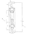
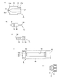
- FIG. 1 It is a figure which shows schematic structure of the syringe which concerns on this invention. It is a figure which shows schematic structure of (a) syringe part, (b) plunger, (c) piston, (d) syringe main body, and (e) drive part which comprise the syringe assembly integrated in the syringe shown in FIG. It is a figure which shows the state by which the plunger was attached to the syringe part shown in FIG. 2, and the injection solution was filled in the filling chamber. It is a figure which shows the state by which the piston and the drive part were attached to the syringe main body shown in FIG.
- FIG. 3A It is a figure which shows the flow which attaches the syringe part and plunger which are shown to FIG. 3A to the syringe main body, piston, and drive part which are shown to FIG. 3B, and forms a syringe assembly.
- FIG. 3B It is a figure which shows schematic structure of the syringe main body which concerns on a 2nd Example.
- FIG. 3B It is a figure which shows schematic structure of the cylindrical member used in the injection device which concerns on a 3rd Example.
- FIG. 3rd Example It is a figure which shows schematic structure of the syringe assembly formed using the cylindrical member shown in FIG.
- FIG. 4th Example It is a figure which shows schematic structure of the piston which concerns on a 4th Example.
- distal side and proximal end side are used as terms representing the relative positional relationship in the longitudinal direction of the syringe 1.
- the “front end side” represents a position closer to the distal end of the syringe 1 described later, that is, a position closer to the injection port 31a, and the “base end side” is a direction opposite to the “front end side” in the longitudinal direction of the syringe 1. That is, the direction on the drive unit 7 side is shown.
- FIG. 1 is a diagram showing a schematic configuration of the syringe 1, and is also a cross-sectional view along the longitudinal direction of the syringe 1.
- the syringe 1 includes a subassembly (refer to FIG. 3A described later) composed of a later-described syringe unit 3 and a plunger 4, and a subassembly composed of a syringe body 6, a piston 5 and a drive unit 7 (described later).
- the syringe assembly 10 is integrally assembled with the housing (syringe housing) 2 so as to be assembled.
- injection target substances that are injected into the injection target region by the syringe 1 are collectively referred to as “injection solution”.
- injection solution the component to be delivered to the skin structure or the like that is the injection target area may or may not be dissolved.
- the injection target substance can be pressurized from the injection port 31a to the injection target area. If it can inject
- the syringe assembly 10 is configured to be detachable from the housing 2.
- the filling chamber 32 (see FIG. 3A) formed between the syringe part 3 and the plunger 4 included in the syringe assembly 10 is filled with an injection solution, and the syringe assembly 10 is injected with the injection solution. It is a unit that is disposable every time.
- a battery 9 for supplying power to an igniter 71 (see FIG. 2 described later) included in the drive unit 7 of the syringe assembly 10 is included.
- the power supply from the battery 9 is performed by the user pressing the button 8 provided on the housing 2, so that the electrode on the housing 2 side and the electrode on the drive unit 7 side of the syringe assembly 10 are connected via the wiring. Will be done between.
- the electrode on the housing 2 side and the electrode on the drive unit 7 side of the syringe assembly 10 are designed so that the shape and position of both electrodes are automatically contacted when the syringe assembly 10 is attached to the housing 2.
- the housing 2 is a unit that can be used repeatedly as long as the electric power that can be supplied to the drive unit 7 remains in the battery 9. In the housing 2, when the power of the battery 9 is exhausted, only the battery 9 may be replaced and the housing 2 may continue to be used.
- FIG. 2A shows the configuration of the syringe unit 3
- FIG. 2B shows the configuration of the plunger 4.
- the syringe part 3 has a nozzle part 31 including a filling chamber 32 that is a space capable of containing an injection solution, and a plunger 4 is disposed so as to be slidable in the filling chamber 32.
- the body 30 of the syringe unit 3 may be made of, for example, known nylon 6-12, polyarylate, polybutylene terephthalate, polyphenylene sulfide, or liquid crystal polymer. These resins may contain a filler such as glass fiber or glass filler. In polybutylene terephthalate, 20 to 80% by mass of glass fiber, and in polyphenylene sulfide, 20 to 80% by mass of glass fiber, The liquid crystal polymer may contain 20 to 80% by mass of mineral.
- the plunger 4 is arranged so as to be slidable in the direction of the nozzle portion 31 (front end side direction), and between the plunger 4 and the body of the syringe portion 3.
- the formed space is a space in which the injection solution is accommodated.
- the plunger 4 slides in the filling chamber 32, the injection liquid stored in the filling chamber 32 is pressed and injected from the flow path (injection port 31 a) provided on the tip side of the nozzle portion 31. Will be. Therefore, the plunger 4 is formed of a material that slides smoothly in the filling chamber 32 and does not leak the injection solution from the plunger 4 side.
- a specific material of the plunger 4 for example, butyl rubber or silicon rubber can be adopted.
- styrene elastomers hydrogenated styrene elastomers, polyolefins such as polyethylene, polypropylene, polybutene, and ⁇ -olefin copolymers, oils such as para, process oil, and powders such as talc, cast, mica, etc.
- lifted The thing which mixed the inorganic substance is mention
- various rubber materials such as polyvinyl chloride elastomer, olefin elastomer, polyester elastomer, polyamide elastomer, polyurethane elastomer, natural rubber, isoprene rubber, chloroprene rubber, nitrile-butadiene rubber, styrene-butadiene rubber (especially added) Sulfurized ones) and mixtures thereof can be used as the material of the plunger 4.
- various rubber materials such as polyvinyl chloride elastomer, olefin elastomer, polyester elastomer, polyamide elastomer, polyurethane elastomer, natural rubber, isoprene rubber, chloroprene rubber, nitrile-butadiene rubber, styrene-butadiene rubber (especially added) Sulfurized ones) and mixtures thereof can be used as the material of the plunger 4.
- the plunger 4 has a head portion 41 and a body portion 42, and a neck portion 43 having a diameter smaller than the diameter of the head portion 41 and the body portion 42 is between them. It is connected.
- the reason why the diameter of the neck portion 43 is reduced in this way is to form an accommodation space for an O-ring that becomes a seal member.
- the contour on the tip side of the head 41 has a shape that substantially matches the contour of the inner wall surface of the nozzle portion 31.
- the plunger 4 and the inner wall surface of the nozzle portion 31 are spaced from each other. Can be made as small as possible, and the waste of the injection solution can be suppressed.
- the shape of the plunger 4 is not limited to a specific shape as long as a desired effect is obtained in the syringe of the present invention.
- the plunger 4 is provided with a rod portion 44 extending from the end surface on the base end side of the body portion 42 in the direction of the base end side.
- the rod portion 44 is sufficiently small in diameter as compared to the body portion 42, but has a diameter that allows the user to grip the rod portion 44 and move the inside of the filling chamber 32. Further, even when the plunger 4 is at the innermost position (most distal side position) of the filling chamber 32 of the syringe part 3, the rod part 44 protrudes from the end face on the proximal end side of the syringe part 3, and the user makes the rod part 44.
- the length of the rod portion 44 is determined so as to be gripped.
- the inner diameter of the flow path provided in the nozzle part 31 on the syringe part 3 side is formed smaller than the inner diameter of the filling chamber 32.
- an annular shield part 31b is provided on the distal end side of the syringe part 3 and in the vicinity of the nozzle part 31 so as to surround the injection port 31a.
- the shield portion 31b can block the injected injection solution so that the injection solution does not scatter around the injection solution.
- the tip of the nozzle part 31 where the injection port 31a is located may protrude slightly from the end face of the shield part 31b.
- a threaded portion 33 a for connecting a syringe main body 6 and a syringe portion 3 described later is formed on the neck portion 33 located on the proximal end side of the syringe portion 3.
- the diameter of the neck 33 is set smaller than the diameter of the body 30.
- the piston 5 is configured to be pressurized by the combustion product generated by the igniter 71 and slide in a through hole 64 formed in the body 60 of the syringe body 6.
- a coupling recess 61 is formed on the distal end side of the syringe body 6 with the through hole 64 as a reference.
- the coupling recess 61 is a portion that couples with the neck portion 33 of the syringe portion 3, and a screw portion 62 a that engages with the screw portion 33 a provided on the neck portion 33 is formed on the side wall surface 62 of the coupling recess 61. ing.
- the through hole 64 and the coupling recess 61 are connected by the communication part 63, and the diameter of the communication part 63 is set smaller than the diameter of the through hole 64.
- the syringe body 6 is formed with a drive portion recess 65 on the base end side with the through hole 64 as a reference.
- the piston 5 is made of metal and has a first body 51 and a second body 52.
- the piston 5 is disposed in the through hole 64 such that the first body 51 faces the connection recess 61 and the second body 52 faces the drive part recess 65.
- the piston 5 slides in the through hole 64 while the first body 51 and the second body 52 are opposed to the inner wall surface of the through hole 64 of the syringe body 6.
- the first body portion 51 and the second body portion 52 are connected by a connecting portion that is thinner than the diameter of each body portion, and the space between both body portions formed as a result is a through hole 64.
- an O-ring or the like is disposed.
- the piston 5 may be made of resin, and in that case, a metal may be used in combination in a portion where heat resistance and pressure resistance are required.
- the end surface on the distal end side of the first body 51 is provided with a pressing column 53 having a diameter smaller than that of the first body 51 and smaller than the diameter of the communication part 63 of the syringe body 6.
- the pressing column portion 53 is provided with an accommodation hole 54 that opens to the end surface on the distal end side thereof, whose diameter is equal to or larger than the diameter of the rod portion 44, and whose depth is deeper than the length of the rod portion 44. . Therefore, when the piston 5 is pressurized by the combustion product of the igniter 71 via the end surface on the distal end side of the pressing column portion 53, the pressure energy is applied to the proximal end side of the trunk portion 42 of the plunger 4. It can be transmitted to the end face.
- the shape of the piston 5 is not limited to the shape shown in FIG.
- the drive unit 7 has a body 72 formed in a cylindrical shape, and has an igniter 71 that is an electric igniter that burns an explosive component and generates energy for injection. It is attached to the drive unit recess 65 of the syringe body 6 so that energy can be transmitted to the second body 52 of the piston 5.
- the body of the drive unit 7 may be one in which an injection molded resin is fixed to a metal collar. A known method can be used for the injection molding.
- the resin material of the body 72 of the drive unit 7 is formed of the same resin material as that of the body 30 of the syringe unit 3.
- the explosive used in the igniter 71 is preferably explosive containing zirconium and potassium perchlorate (ZPP), explosive containing titanium hydride and potassium perchlorate (THPP), titanium and potassium perchlorate.
- ZPP zirconium and potassium perchlorate
- THPP titanium hydride and potassium perchlorate
- TiPP titanium hydride and potassium perchlorate
- APP titanium and potassium perchlorate
- ABO aluminum and bismuth oxide
- AMO aluminum and molybdenum oxide
- ACO gunpowder containing aluminum and copper oxide (ACO)
- Explosives containing aluminum and iron oxide (AFO) or explosives composed of a combination of these explosives.
- These explosives generate high-temperature and high-pressure plasma at the time of combustion immediately after ignition. However, when the combustion product is condensed at a normal temperature and does not contain a gas component, the generated pressure rapidly decreases.
- Other explosives may be used as explosives as long as appropriate injection is possible.
- the explosive combustion in the igniter 71 is performed.
- a gas generating agent or the like that burns with a combustion product generated by the above to generate gas can be disposed in the igniter 71 or the through hole 64 of the syringe body 6.
- the configuration in which the gas generating agent is arranged in the igniter 71 is a known technique as disclosed in International Publication No. 01-031282, Japanese Patent Application Laid-Open No. 2003-25950, and the like.
- the gas generating agent a single base smokeless gunpowder composed of 98% by mass of nitrocellulose, 0.8% by mass of diphenylamine and 1.2% by mass of potassium sulfate can be mentioned. It is also possible to use various gas generating agents that are used in gas generators for airbags and gas generators for seat belt pretensioners. It is possible to change the combustion completion time of the gas generating agent by adjusting the size, size and shape of the gas generating agent when disposed in the through hole 64, in particular, the surface shape. A change in pressure applied to the injection solution can be a desired change, that is, a change in which the injection solution can appropriately reach the injection target region. In the present invention, it is assumed that the gas generating agent used as necessary is also included in the drive unit 7.
- FIG. 3A discloses a subassembly composed of the syringe part 3 and the plunger 4.
- the subassembly is formed by inserting the plunger 4 into the filling chamber 32 of the syringe unit 3.
- the injection port 31a is immersed in a container filled with the injection solution, and the plunger 4 is opened in the filling chamber 32 while maintaining the state. Pull back to the base side, that is, the base end side of the syringe part 3.
- the injection solution enters the filling chamber 32 from the injection port 31a, and the filling chamber 32 is filled with the injection solution 320.
- the plunger 4 is pulled out until the end surface on the proximal end side of the body portion 42 of the plunger 4 slightly protrudes from the end surface on the proximal end side of the syringe portion 3.
- the amount of the injection solution 320 is not necessarily a constant amount depending on the amount of the user pulling out the plunger 4.
- FIG. 3B discloses a subassembly composed of a syringe body 6, a piston 5 and a drive unit 7.
- the piston 5 is inserted from the proximal end side of the syringe main body 6 shown in FIG.
- the piston 5 is inserted into the through hole 64 so that the pressing column portion 53 faces the coupling recess 61 side.
- the end surface on the front end side of the piston 5, that is, the end surface on the front end side of the pressing column portion 53 in which the accommodation hole 54 opens, is in a state of protruding a predetermined amount from the bottom surface (surface orthogonal to the side wall surface 62) of the coupling recess 61.
- the piston 5 are positioned as follows.
- a known technique such as setting a positioning mark in the through hole 64 or using a positioning jig may be used as appropriate.
- the drive part 7 is attached to the recessed part 65 for drive parts.
- the fixing force in the through-hole 64 of the piston 5 is such that the piston 5 can slide in the through-hole 64 sufficiently smoothly depending on the pressure received from the combustion product by the igniter 71 of the drive unit 7, and As will be described later, when the subassembly shown in FIG. 3A is attached to the subassembly shown in FIG. 3B, it sufficiently resists the force that the piston 5 receives from the plunger 4, and the position of the piston 5 does not change. It is said to be about.
- the syringe assembly 10 is formed by attaching the subassembly shown in FIG. 3A to the subassembly shown in FIG. 3B.
- the formation process is shown in FIG. 3C.
- the neck portion 33 of the syringe portion 3 is connected to the syringe body 6 while the rod portion 44 of the plunger 4 faces the piston 5 side.
- the syringe unit 3 and the syringe body 6 are fitted into the recess 61 and are joined by screwing the screw portions 33a and 62a.
- the rod portion 44 of the plunger 4 enters and is accommodated in the accommodation hole 54 provided in the pressing column portion 53 of the piston 5.
- the end surface on the distal end side of the pressing column portion 53 is in contact with the end surface on the proximal end side of the body portion 42 of the plunger 4 (the state shown in FIG. 3C (b)). Since the accommodation hole 54 is large enough to accommodate the rod portion 44, the inner wall surface behind the accommodation hole 54 (particularly, the bottom surface of the accommodation hole 54) is the rod portion in this contact state. 44 is not in contact with the end portion on the base end side, and therefore the rod portion 44 does not receive a load from the piston 5 side.
- the piston 5 is inserted into the through hole 64 as described above. Since the position is fixed with a sufficient frictional force, the plunger 4 is pushed by the pressing column 53 so as to advance toward the injection port 31a, and the state shown in FIG. 3C (c) is reached. As shown in FIG. 3C, the plunger 4 is pushed by ⁇ d from the time when the pressing column portion 53 and the body portion 42 start to contact to the final screwing position shown in FIG. 3C. When the plunger 4 is pushed in this way, a part of the injection solution 320 in the filling chamber 32 is discharged from the injection port 31a.
- the formation of the syringe assembly 10 is completed when the pressing column portion 53 and the body portion 42 reach the final screwing position.
- the piston 5 is positioned at a predetermined position with respect to the syringe body 6, and the position of the plunger 4 in the filling chamber 32 of the syringe unit 3 is mechanically determined with reference to the piston 5.
- the user after the suction of the injection solution in the syringe unit 3 shown in FIG. 3A, the user only connects the sub-assemblies shown in FIGS. 3A and 3B. In this series of assembling operations, an operation such as accurately measuring an injection solution is not required. However, in the syringe assembly 10, the user is not required to strictly measure the amount of the injection solution, but the amount of the injection solution filled in the filling chamber is accurately set to a predetermined amount.
- the syringe assembly 10 is attached to the housing 2, and the user presses the button 8 in a state where the injection port 31 a is brought into contact with the injection target region, so that the injection is performed via the piston 5 and the plunger 4.
- the liquid 320 is pressurized and the injection is performed. Since the end portion of the rod portion 44 is not in contact with the inner wall surface in the accommodation hole 54, a load is not applied to the rod portion 44 during pressurization by the igniter 71, and the breakage is sufficiently avoided. As described above, in the syringe 1, it is possible to realize injection of an accurate amount of the injection solution while being extremely easy to handle.
- FIG. 4 shows a schematic configuration of the syringe body 6 according to the present embodiment.
- the same reference number is attached
- the body 60 is formed so as to be divided into a first body (first main body portion) 60a and a second body (second main body portion) 60b.
- a connecting recess 61 is formed on the first body 60a side, and a driving portion recess 65 is formed on the second body 60b side.
- the 1st body 60a and the 2nd body 60b are screwed together by the connection part 60c provided mutually, and the syringe main body 6 is formed.
- the first body 60a is provided with a first through hole 64a in which the piston 5 is slidably accommodated, and the second body 60b is a first space as a space where combustion products from the igniter 71 can reach. Two through holes 64b are provided.
- the first through-hole 64a and the second through-hole 64b are in a state in which the central axes of both holes coincide with each other when the syringe body 6 is formed.
- the diameter DA of the first through hole 64a is set larger than the diameter DB of the second through hole 64b. Therefore, a step is formed by the end surface 66 on the proximal end side of the first body 60a and the end surface 67 on the distal end side of the second body 60b, and the step surface 67 is higher toward the center of the through hole. It has become. Therefore, when the piston 5 is accommodated in the first through hole 64a, the movement of the piston 5 toward the base end side is restricted by the step being caught by the piston 5.
- the first through hole 64a is divided into the first body 60a and the second body 60b.
- the piston 5 is inserted into. In that case, it inserts in the 1st through-hole 64a so that the press pillar part 53 of piston 5 may face the connection recessed part 61 side.
- the second body 60b is screwed into the first body 60a, and the driving unit 7 is attached to the driving unit recess 65.
- the fixing force in the first through hole 64a of the piston 5 is such that the piston 5 slides through the through hole 64 sufficiently smoothly by the pressure received from the combustion product by the igniter 71 of the drive unit 7. It only needs to be able to move.
- the syringe assembly 10 is formed by attaching the subassembly shown in FIG. 3A to the subassembly formed by incorporating the piston 5 into the syringe body 6 as described above. .
- the rod portion 44 of the plunger 4 is accommodated in the accommodation hole 54 of the piston 5, and the pressing column portion 53 of the piston 5 and the body portion 42 of the plunger 4 come into contact with each other. 5 is pushed to the base end side in the first through hole 64a.
- the movement of the piston 5 toward the base end side is restricted by the step (step formed by the end surfaces 66 and 67).
- the end surface on the front end side of the pressing column portion 53 protrudes a predetermined amount from the bottom surface (the surface orthogonal to the side wall surface 62) of the coupling recess 61, as in the above embodiment.
- the piston 5 is formed so that As a result, in the state where the syringe assembly 10 is formed, the position of the plunger 4 in the syringe part 3 is mechanically determined with reference to the position of the piston 5 in the syringe body 6, and thus finally The amount of the injection 320 stored in the filling chamber 32 can be set to a predetermined amount.
- FIG. 5 shows a schematic configuration of the cylindrical member 68 used in the syringe 1 according to the present embodiment
- FIG. 6 shows a schematic configuration of the syringe assembly 10 formed by using the cylindrical member 68. Show.
- the same components as those in the syringe assembly 10 shown in FIGS. 5 and 6 are denoted by the same reference numerals, and detailed description thereof is omitted.
- This embodiment is different from the first embodiment in that a configuration is adopted in which the movement of the piston 5 to the proximal end side is regulated by the tubular member 68, and the other points are substantially the same. It is.
- FIG. 5 shows a cross section of the tubular member 68.
- the tubular member 68 has an opening 68b on the distal end side and an opening 68e on the proximal end side, and the outer diameter is approximately equal to the inner diameter of the through hole 64. It has the side part 68c which becomes the same.
- a space formed by being surrounded by the side portion 68c is an internal space (arrival space) 68f of the cylindrical member 68.
- a protrusion 68a is formed that rises slightly from the side 68c toward the internal space 68f.
- the opening 68b is formed by the peripheral edge of the protrusion 68a.
- a flange portion 68d extending from the side portion 68c to the side opposite to the internal space 68f is provided.
- the cylindrical member 68 configured in this manner has the syringe main body 6 in a state where the collar portion 68d is hooked on the stepped portion of the concave portion 65 for the driving portion after the piston 5 is inserted into the through hole 64 of the syringe main body 6.
- the drive unit 7 is attached to the drive unit recess 65 to form a sub-assembly on the syringe body 6 side.
- the protrusion 68a of the cylindrical member 68 is positioned in the syringe body 6 with the drive portion recess 65 as a reference. At this time, the protrusion 68a may not be in contact with the piston 5.
- the syringe assembly 10 is formed by attaching the subassembly shown in FIG. 3A to the subassembly formed by incorporating the piston 5 into the syringe body 6 as described above. .
- the rod portion 44 of the plunger 4 is accommodated in the accommodation hole 54 of the piston 5, and the pressing column portion 53 of the piston 5 and the body portion 42 of the plunger 4 come into contact with each other. 5 is pushed through the through hole 64 toward the base end.
- the movement of the piston 5 toward the proximal end side is restricted by the protrusion 68 a of the cylindrical member 68.
- the end surface on the front end side of the pressing column portion 53 protrudes a predetermined amount from the bottom surface of the coupling recess 61 (the surface perpendicular to the side wall surface 62), as in the above embodiment.
- the piston 5 is formed so that As a result, in the state where the syringe assembly 10 is formed, the position of the plunger 4 in the syringe part 3 is mechanically determined with reference to the position of the piston 5 in the syringe body 6, and thus finally The amount of the injection 320 stored in the filling chamber 32 can be set to a predetermined amount.
- the combustion product produced by the igniter 71 enters the internal space 68f from the opening 68e of the cylindrical member 68, and the opening The piston 5 is pressed through 68b. Further, the position of the piston 5 in the syringe assembly 10 can be adjusted by changing the length of the side portion 68c of the cylindrical member 68, that is, the distance between the collar portion 68d and the protrusion 68a. It is possible to adjust the predetermined amount of the injection solution 320 accommodated in the filling chamber 32.
- FIG. 7 shows a schematic configuration of the piston 5 according to the present embodiment, particularly the pressing column portion 53.
- a contact portion 54 a that contacts the side surface of the rod portion 44 in a state where the rod portion 44 is inserted into the storage hole 54 and a non-contact portion 54 b that does not contact are formed in the storage hole 54.
- the contact portion 54 a is a protruding portion that protrudes inward from the inner peripheral surface in the cross section of the accommodation hole 54 and extends in the axial direction of the accommodation hole 54.
- the number of contact portions 54a formed in the accommodation hole 54 is at least two and is not limited to a specific number.
- the rod portion 44 is inserted into the accommodation hole 54 while maintaining a state in which a part of the side surface of the rod portion 44 is in contact with the contact portion 54a.
- the end portion on the proximal end side of the rod portion 44 is the inner wall surface (or accommodation space) behind the accommodation holes 54, as in the above-described embodiments. It does not contact the bottom surface of the hole 54.
- part of the back of the accommodation hole 54 is connected with the opening part of the accommodation hole 54 via the non-contact surface 54b.
- the contact part 54 a comes into contact with the side surface of the rod part 44, whereby the integrity of the piston 5 and the plunger 4 can be improved.
- the combustion energy of the combustion product can be efficiently transmitted to the injection solution during pressurization by the combustion product.
- the non-contact part 54b is provided in the accommodation hole 54, and the portion at the back of the accommodation hole 54 and the opening of the accommodation hole 54 are communicated with each other, so that the rod part 44 can be easily inserted into the accommodation hole 54. It becomes possible to accurately position the plunger 4 in the three-dimensional object 10.
- the cells to be injected and the cultured cells in the scaffold tissue / scaffold It is possible to seed stem cells and the like.
- the cells to be injected in addition to the case of injecting the above-mentioned injection solution into the skin structure, for example, in the field of regenerative medicine for humans, the cells to be injected and the cultured cells in the scaffold tissue / scaffold It is possible to seed stem cells and the like.
- the cells to be injected in addition to the case of injecting the above-mentioned injection solution into the skin structure, for example, in the field of regenerative medicine for humans, the cells to be injected and the cultured cells in the scaffold tissue / scaffold It is possible to seed stem cells and the like.
- cells that can be appropriately determined by those skilled in the art depending on the site to be transplanted and the purpose of recellularization such as endothelial cells, endothelial precursor cells, bone marrow cells, prebones Blast cells, chondrocytes, fibroblasts, skin cells, muscle cells, liver cells, kidney cells, intestinal cells, stem cells, and any other cells considered in the field of regenerative medicine can be injected with the syringe 1. .
- the syringe 1 according to the present invention can also be used for delivery of DNA or the like to cells, scaffold tissues, scaffolds, etc. as described in JP-T-2007-525192.
- the use of the syringe 1 according to the present invention is more preferable than the case of delivery using a needle because the influence on the cells, the scaffold tissue / scaffold and the like can be suppressed.
- the syringe 1 according to the present invention is suitable also when various genes, tumor suppressor cells, lipid envelopes, etc. are directly delivered to a target tissue or when an antigen gene is administered to enhance immunity against a pathogen. Used for.
- various disease treatment fields fields described in JP 2008-508881, JP 2010-503616, etc.
- immunomedical fields fields described in JP 2005-523679, etc.
- the syringe 1 can be used, and the field in which the syringe 1 can be used is not intentionally limited.
Abstract
In an injector provided with an injector body, a syringe section, and a piston, a plunger has a rod section which, in a mounted state in which the syringe section is mounted to the injector body, extends from the base end side-end surface of the plunger toward the piston. The piston has, on the front end side thereof, a housing hole having an opening into which the rod section of the plunger can be inserted, and the housing hole is formed so that the base end-side end of the rod section is housed therein without being in contact with the piston. In the mounted state in which the rod section is housed within the housing hole, the front end-side end surface of the piston is in contact with the base end-side end surface of the plunger, enabling the plunger to slide toward the injection opening side, and the plunger in a filling chamber is positioned at a predetermined position with reference to the position of the piston disposed in a through-hole, the predetermined position being the position where the amount of a substance to be injected, which is within the filling chamber, is a predetermined amount. Consequently, the injector can be handled easily, and the filling of a substance to be injected, such as an injection solution, can be accurately performed.
Description
本発明は、注射目的物質を注射対象領域に注射する注射器に関する。
The present invention relates to a syringe for injecting a substance to be injected into a region to be injected.
注射器において注射液を射出するための準備として、注射器内に注射液を充填する作業がある。ここで、特許文献1には、注射液室内に注射液を充填する技術が開示されている。具体的には、針無注射器50は、本体としての第1グリップ(本体)GAと第1グリップGAに対して回転摺動する第2グリップGBと、第1グリップGAの先端に捩じ込まれた着脱自在の先端ノズル51とから構成されている。ノズル51には吸引された薬液が入る注射液室(シリンダ室)52とジェット噴射口(オリフィス)53が形成されており、注射液室52の内には往復摺動できるようにピストン54が配設される。ピストン54は前記第2グリップGBに連結されており、注射液を吸引するときは、ジェット噴射口53を注射液に浸した状態で、第2グリップGBが回転操作されてピストン54が基端側に引上げられる。
As preparation for injecting an injection solution in a syringe, there is an operation of filling the injection solution in the syringe. Here, Patent Document 1 discloses a technique for filling an injection solution into an injection solution chamber. Specifically, the needleless syringe 50 is screwed into the first grip (main body) GA as the main body, the second grip GB that rotates and slides with respect to the first grip GA, and the tip of the first grip GA. And a detachable tip nozzle 51. The nozzle 51 is formed with an injection liquid chamber (cylinder chamber) 52 and a jet injection port (orifice) 53 into which the aspirated drug solution enters, and a piston 54 is arranged in the injection liquid chamber 52 so as to be slidable back and forth. Established. The piston 54 is connected to the second grip GB. When the injection liquid is sucked, the second grip GB is rotated in a state where the jet injection port 53 is immersed in the injection liquid, and the piston 54 is moved to the proximal side. Pulled up.
また、特許文献2には、射出時に注射液を加圧するピストンを引っ張ることで注射器内に負圧の状態を形成し、ノズルから注射液を注射器内に吸い込む構成が開示されている。その際にピストンを引っ張りやすくするために、ピストンの基端側の端面から延在するロッドが設けられている。ユーザは、このロッドを把持しながらピストンを引っ張ることになる。また、特許文献3にも、ピストンの基端側の端面にロッドが設けられた構成が開示されている。
Also, Patent Document 2 discloses a configuration in which a negative pressure state is formed in the syringe by pulling a piston that pressurizes the injection solution at the time of injection, and the injection solution is sucked into the syringe from the nozzle. In order to make it easy to pull the piston at that time, a rod extending from the end face on the base end side of the piston is provided. The user pulls the piston while holding the rod. Patent Document 3 also discloses a configuration in which a rod is provided on an end surface on the base end side of the piston.
上記特許文献1に開示の従来技術によれば、ピストン54と第2グリップGBがピストンロッド56を介して接続されており、注射液の吸引時には、第2グリップGBが基端側にねじ上げられる動きに従ってピストン54を基端側に引き上げる必要があるため、ピストン54とピストンロッド56は簡単に外れないような構成にする必要がある。このためノズル51は第1グリップGAの先端に着脱可能に取り付けられるものであるが、ピストン54の存在によりノズル51の着脱が困難となり得る。
According to the prior art disclosed in Patent Document 1, the piston 54 and the second grip GB are connected via the piston rod 56, and the second grip GB is screwed up to the proximal end side when sucking the injection solution. Since it is necessary to pull up the piston 54 to the proximal end side according to the movement, the piston 54 and the piston rod 56 must be configured so as not to be easily detached. For this reason, the nozzle 51 is detachably attached to the tip of the first grip GA, but the presence of the piston 54 may make it difficult to attach and detach the nozzle 51.
また、上記特許文献1の開示の従来技術では、注射液室52に吸引される注射液の量は、グリップに目盛られたスケールで調整することから、その読み間違いにより正確な量の注射液の充填が困難となりやすい。また、上記特許文献2、3の開示の従来技術では、正確な量の注射液の充填に関する示唆は一切されていない。
In the prior art disclosed in Patent Document 1, the amount of the injection solution sucked into the injection solution chamber 52 is adjusted by a scale graduated from the grip. Filling tends to be difficult. Moreover, in the prior art disclosed in Patent Documents 2 and 3, there is no suggestion regarding filling of an accurate amount of injection solution.
そこで、本発明は、上記した問題に鑑み、注射器の取り扱いが容易であり、且つ注射液等の注射目的物質の充填が正確に行い得る注射器を提供することを目的とする。
Therefore, in view of the above-described problems, an object of the present invention is to provide a syringe that is easy to handle and can be accurately filled with an injection target substance such as an injection solution.
上記課題を解決するために、本発明は、ピストンを有する注射器本体に、注射液を収容する充填室を有するシリンジ部を取り付けるときに、充填室内を摺動可能なプランジャの位置が、ピストンとプランジャとの接触により該ピストンの位置を基準として決定されることで、最終的に注射器が形成された状態において充填室内に収容された注射目的物質の量が自動的に所定量とされる。そのため、ユーザは、複雑な操作を行うことなく正確に所定量の注射目的物質を注射器内に準備することが可能となる。なお、本発明に係る注射器おいて、「先端側」とは、注射器から注射目的物質が射出される射出口が配置されている側を意味し、「基端側」とは、注射器において先端側とは反対の側を意味するものであり、これらの文言は、特定の箇所や位置を限定的に指すものではない。
In order to solve the above-mentioned problems, the present invention provides a plunger and a plunger that are slidable in a filling chamber when a syringe part having a filling chamber for containing an injection solution is attached to a syringe body having a piston. Is determined with reference to the position of the piston as a reference, and the amount of the injection target substance accommodated in the filling chamber in the state where the syringe is finally formed is automatically set to a predetermined amount. Therefore, the user can accurately prepare a predetermined amount of the injection target substance in the syringe without performing a complicated operation. In the syringe according to the present invention, the “tip side” means the side where the injection port through which the injection target substance is injected from the syringe is arranged, and the “base end side” means the tip side in the syringe. Means the opposite side, and these terms do not refer specifically to a particular location or position.
具体的には、本発明は、注射目的物質を注射対象領域に注射する注射器であって、軸方向に形成された貫通孔を有する注射器本体と、前記貫通孔内を摺動可能なピストンと、前記注射目的物質を収容可能な充填室と、該充填室内で摺動可能なプランジャと、該プランジャの摺動により加圧された該充填室内の該注射目的物質が流れ該充填室よりも内径が細い流路を含み、該流路の先端に形成された射出口から該注射目的物質を射出するノズル部と、を有するシリンジ部であって、前記注射器本体の先端側に取り付けられるシリンジ部と、火薬を燃焼させる点火装置を有し、該点火装置により生成される燃焼生成物を介して前記注射目的物質を前記ノズル部から射出するための射出エネルギーを前記ピストンを伝って前記プランジャに付与する駆動部と、を備える。そして、前記プランジャは、前記シリンジ部の前記注射器本体への取付状態において、基端側の端面から該注射器本体の前記貫通孔に配置されている前記ピストンに向かって延在するロッド部を有し、前記プランジャが前記充填室内に配置された状態で、前記ロッド部を介して該プランジャが基端側に移動されると、前記射出口を介して該充填室内に前記注射目的物質が充填されるように、前記シリンジ部は形成される。更に、前記ピストンの先端側に、前記取付状態において、前記プランジャの前記ロッド部が挿入可能な開口を有し、該ロッド部の基端側の端部が該ピストンに接触しないで収容されるように形成された収容孔が設けられ、前記取付状態において、前記ロッド部が前記収容孔に収容された状態で、前記ピストンの先端側の端面が、前記プランジャの基端側の端面と接触し該プランジャが前記射出口側に摺動可能とされ、且つ、前記貫通孔内に配置された該ピストンの位置を基準としたときに、前記充填室内における該プランジャの位置が、該充填室内の前記注射目的物質の量を所定量とする所定の位置に決定される。
Specifically, the present invention is a syringe for injecting an injection target substance into a region to be injected, a syringe body having a through hole formed in an axial direction, a piston slidable in the through hole, A filling chamber capable of containing the injection target substance; a plunger slidable in the filling chamber; and the injection target substance in the filling chamber pressurized by sliding of the plunger flows and has an inner diameter larger than that of the filling chamber. A syringe part including a thin channel and having a nozzle part for injecting the injection target substance from an injection port formed at the tip of the channel, wherein the syringe part is attached to the tip side of the syringe body; An ignition device for burning explosives is provided, and injection energy for injecting the injection target substance from the nozzle portion through the combustion product generated by the ignition device is applied to the plunger through the piston. Comprising a drive unit. And the said plunger has the rod part extended toward the said piston arrange | positioned in the said through-hole of this syringe main body from the end surface of the said syringe main body in the attachment state to the said syringe main body of the said syringe part. When the plunger is moved to the proximal end side through the rod portion in a state where the plunger is disposed in the filling chamber, the injection target substance is filled into the filling chamber through the injection port. Thus, the syringe part is formed. Further, the piston has an opening into which the rod portion of the plunger can be inserted in the attached state so that the proximal end of the rod portion is accommodated without contacting the piston. In the mounted state, the end surface on the distal end side of the piston is in contact with the end surface on the proximal end side of the plunger and the rod portion is accommodated in the accommodation hole. When the plunger is slidable toward the injection port and the position of the piston arranged in the through hole is used as a reference, the position of the plunger in the filling chamber is the injection in the filling chamber. It is determined at a predetermined position where the amount of the target substance is a predetermined amount.
本発明に係る注射器において、駆動部は、点火装置によって点火される火薬の燃焼エネルギーを射出エネルギーとして採用する。なお、火薬の燃焼エネルギーを射出エネルギーとして利用する場合、火薬としては、例えば、ジルコニウムと過塩素酸カリウムを含む火薬、水素化チタンと過塩素酸カリウムを含む火薬、チタンと過塩素酸カリウムを含む火薬、アルミニウムと過塩素酸カリウムを含む火薬、アルミニウムと酸化ビスマスを含む火薬、アルミニウムと酸化モリブデンを含む火薬、アルミニウムと酸化銅を含む火薬、アルミニウムと酸化鉄を含む火薬のうち何れか一つの火薬、又はこれらのうち複数の組み合わせからなる火薬であってもよい。これらの火薬の特徴としては、その燃焼生成物が高温状態では気体であっても常温では気体成分を含まないため、点火後燃焼生成物が直ちに凝縮を行う結果、本発明の注射器を生体に対する注射に用いた場合、生体の注射対象領域のより浅い部位への効率的な注射が可能となる。また、ガス発生剤の発生エネルギーを射出エネルギーとして利用する場合、ガス発生剤としては、シングルベース無煙火薬や、エアバッグ用ガス発生器やシートベルトプリテンショナ用ガス発生器に使用されている各種ガス発生剤を用いることも可能である。
In the syringe according to the present invention, the drive unit employs the combustion energy of the explosive ignited by the ignition device as the injection energy. In addition, when using the combustion energy of explosives as injection energy, as explosives, for example, explosives containing zirconium and potassium perchlorate, explosives containing titanium hydride and potassium perchlorate, and titanium and potassium perchlorate are included. Gunpowder, powder containing aluminum and potassium perchlorate, powder containing aluminum and bismuth oxide, powder containing aluminum and molybdenum oxide, powder containing aluminum and copper oxide, powder containing aluminum and iron oxide Or explosives composed of a plurality of combinations of these. The characteristics of these explosives are that even if the combustion product is a gas at a high temperature, it does not contain a gas component at room temperature. When used in the above, efficient injection into a shallower part of the injection target region of the living body becomes possible. In addition, when the generated energy of the gas generating agent is used as the injection energy, the gas generating agent includes various gases used in single-base smokeless explosives, gas generators for airbags and gas generators for seat belt pretensioners. It is also possible to use a generator.
上記駆動部による射出エネルギーはピストンを介してプランジャに伝えられ、プランジャが充填室内を摺動することで、充填室に収容されている注射目的物質がノズル部に形成された流路に沿って押し出され、最終的に射出口から注射対象領域に向けて射出される。なお、本発明に係る注射器においては、注射目的物質は、注射対象領域の目的部位で効能が期待される成分を含むものである。そのため、少なくとも駆動部によるエネルギーでの射出が可能であれば、充填室における注射目的物質の収容状態や、液体やゲル状等の流体、粉体、粒状の固体等の注射目的物質の具体的な物理的形態は問われない。たとえば、注射目的物質は液体であり、また固体であっても射出を可能とする流動性が担保されればゲル状の固体であってもよい。そして、注射目的物質には、目的部位に送り込むべき成分が含まれ、当該成分は注射目的物質の内部に溶解した状態で存在してもよく、又は当該成分が溶解せずに単に混合された状態であってもよい。一例を挙げれば、送りこむべき成分として、抗体増強のためのワクチン、美容のためのタンパク質、毛髪再生用の培養細胞等があり、これらが射出可能となるように、液体、ゲル状等の流体に含まれることで注射目的物質が形成される。
The injection energy from the drive unit is transmitted to the plunger through the piston, and the plunger slides in the filling chamber, so that the injection target substance contained in the filling chamber is pushed out along the flow path formed in the nozzle portion. Finally, it is injected from the injection port toward the injection target area. In the syringe according to the present invention, the injection target substance contains a component expected to be effective at the target site in the injection target region. Therefore, as long as at least injection by the drive unit is possible, the state of accommodation of the injection target substance in the filling chamber, and specific injection target substance such as liquid, gel-like fluid, powder, granular solid, etc. The physical form is not questioned. For example, the injection target substance is a liquid, and even if it is a solid, it may be a gel-like solid as long as fluidity enabling injection is ensured. The injection target substance contains a component to be sent to the target site, and the component may exist in a state dissolved in the injection target substance, or the component is simply mixed without being dissolved. It may be. For example, as components to be delivered, there are vaccines for antibody enhancement, proteins for beauty, cultured cells for hair regeneration, etc. By inclusion, a substance for injection is formed.
ここで、本発明に係る注射器では、充填室には当初から注射目的物質が収容されているのではなく、プランジャが充填室内に配置されている状態で、プランジャの基端側に設けられたロッド部を介してユーザが該プランジャを基端側に引っ張ると、充填室内を負圧の状態にすることができる。これにより、射出口を有するノズルを介して注射目的物質を充填室内に吸引することができる。このように、充填室への充填操作を必要とする構成を採用することで、必要とする任意の注射目的物質を注射することが可能となる。そのため、本発明に係る注射器では、シリンジ部と注射器本体とは着脱可能に構成されている。
Here, in the syringe according to the present invention, the injection target substance is not accommodated in the filling chamber from the beginning, but the rod provided on the proximal end side of the plunger in a state where the plunger is disposed in the filling chamber. When the user pulls the plunger to the proximal end side through the section, the filling chamber can be in a negative pressure state. Thereby, the injection target substance can be sucked into the filling chamber through the nozzle having the injection port. As described above, by adopting a configuration that requires a filling operation into the filling chamber, it becomes possible to inject any necessary injection target substance. Therefore, in the syringe according to the present invention, the syringe part and the syringe body are configured to be detachable.
したがって、プランジャに設けられるロッド部は、ユーザが上記の充填操作をするために必要な形状、大きさ(長さ)を有するのが好ましい。例えば、前記プランジャが前記充填室内で最も奥側、すなわち先端側に到達したときの最奥位置にある状態において、前記ロッド部は、該ロッド部の基端側の端部が該充填室内から飛び出した位置にあるような長さを有してもよい。
Therefore, it is preferable that the rod portion provided in the plunger has a shape and size (length) necessary for the user to perform the above filling operation. For example, in a state where the plunger is in the innermost position when the plunger reaches the innermost side, that is, the distal end side, the rod portion protrudes from the filling chamber with the proximal end of the rod portion. It may have a length such that it is in a different position.
そして、ユーザによる充填操作が終了すると、プランジャに設けられたロッド部は、その時点で充填室に充填されている注射目的物質の量に対応する位置に飛び出している。そして、注射器を組み立てるために、このような状態にあるシリンジ部が、ピストンが設けられている注射器本体へ取り付けられる。このとき、ピストンには収容孔が設けられており、シリンジ部の取付状態において、プランジャのロッド部の基端側の端部がピストンの収容孔に、更には収容孔の底面に接触することなく収容される。しかし、プランジャの基端側の端面とピストンの先端側の端面とは互いに接触し、取り付けによってプランジャに対して射出口側に摺動させる力が付与される。この結果、プランジャは、ピストンの位置を基準として所定の位置まで先端側に向かって摺動されることになり、以て、充填室の容量が所定量に機械的に決定されることになる。なお、収容孔はピストンの基端側まで貫通した貫通孔ではない。
Then, when the filling operation by the user is completed, the rod portion provided on the plunger protrudes to a position corresponding to the amount of the injection target substance filled in the filling chamber at that time. And in order to assemble a syringe, the syringe part in such a state is attached to the syringe main body provided with the piston. At this time, the piston is provided with a receiving hole, and in the attached state of the syringe part, the proximal end of the rod part of the plunger does not come into contact with the receiving hole of the piston, and further, the bottom surface of the receiving hole. Be contained. However, the end surface on the proximal end side of the plunger and the end surface on the distal end side of the piston are in contact with each other, and a force for sliding the plunger toward the injection port side is applied to the plunger. As a result, the plunger is slid toward the tip side up to a predetermined position with reference to the position of the piston, so that the capacity of the filling chamber is mechanically determined to be a predetermined amount. The accommodation hole is not a through hole penetrating to the proximal end side of the piston.
すなわち、本発明に係る注射器では、ユーザによるシリンジ部と注射器本体の取付操作によって、シリンジ部側のプランジャが、注射器本体側のピストンに対して常に特定の位置、すなわち注射目的物質が所定量となる上記の所定の位置に自動的に調整されることになる。このとき、ユーザは、単に注射器を組み立てる操作をするのみであるから、その操作は極めて容易なものであり、また、プランジャの所定の位置は、注射器の組立の中で一義的に決定されるものであるから、注射目的物質の調量の精度も正確なものとなる。
That is, in the syringe according to the present invention, the plunger on the syringe unit side is always in a specific position with respect to the piston on the syringe body side, that is, the injection target substance has a predetermined amount by the user's operation of attaching the syringe unit and the syringe body. It is automatically adjusted to the predetermined position. At this time, since the user simply performs the operation of assembling the syringe, the operation is extremely easy, and the predetermined position of the plunger is uniquely determined during the assembly of the syringe. Therefore, the accuracy of metering of the injection target substance is also accurate.
ここで、上述までの注射器において、前記注射器本体には、前記ピストンが前記貫通孔内において基端側に移動することを規制する移動規制部が設けられてもよく、その場合、前記移動規制部によって決定される、前記ピストンが前記貫通孔内において最も基端側に移動し得る位置を基準として、前記プランジャに関する前記所定の位置が決定される。このように移動規制部が設けられることで、シリンジ部を注射器本体に取り付けたときに、注射器本体の貫通孔においてピストンが確実に動かないようにでき、上述したように取り付け状態におけるプランジャの位置を、的確に所定の位置に合わせることが可能となる。
Here, in the syringe up to the above, the syringe main body may be provided with a movement restricting portion that restricts movement of the piston to the proximal end side in the through hole. The predetermined position with respect to the plunger is determined on the basis of the position where the piston can move to the most proximal side in the through hole. By providing the movement restricting portion in this way, when the syringe portion is attached to the syringe main body, the piston can be reliably prevented from moving in the through hole of the syringe main body, and the position of the plunger in the attached state can be changed as described above. It becomes possible to accurately adjust to a predetermined position.
ここで、移動規制部の一例として、2つの形態を例示できる。第1の形態としては、前記注射器本体は、先端側に位置する第1本体部と、基端側に位置する第2本体部とを有するように構成されてもよい。この場合、前記第1本体部は、その内部に第1の所定径を有し前記ピストンが摺動する第1の貫通孔を有し、前記第2本体部は、その内部に前記第1の所定径より小さい第2の所定径を有し、前記点火装置によって生成される燃焼生成物が到達する第2の貫通孔を有する。そして、前記第1本体部と前記第2本体部が結合されて前記注射器本体が形成されると、前記第1の貫通孔と前記第2の貫通孔の結合部位に、前記移動規制部となる段差が形成される。
Here, two forms can be exemplified as an example of the movement restriction unit. As a 1st form, the said syringe main body may be comprised so that it may have a 1st main body part located in the front end side, and a 2nd main body part located in a base end side. In this case, the first body portion has a first through hole in which the piston has a first predetermined diameter, and the second body portion has the first through hole therein. It has a second predetermined diameter smaller than the predetermined diameter, and has a second through-hole through which the combustion product generated by the ignition device reaches. And if the said 1st main-body part and the said 2nd main-body part are couple | bonded and the said syringe main body is formed, it will become the said movement control part in the coupling | bond part of a said 1st through-hole and a said 2nd through-hole. A step is formed.
すなわち、第1の形態では、ピストンが摺動する第1の貫通孔と燃焼生成物が到達する第2の貫通孔の径を異ならせることで、第1本体部と第2本体部との結合部位に段差を形成させる。当該段差があることでピストンが基端側に摺動することが規制されることになる。なお、第1の貫通孔と第2の貫通孔とは必ずしも同軸上に配置される必要はなく、第2の貫通孔に燃焼生成物が到達し、その到達した燃焼生成物が有するエネルギーがピストンに伝わりピストンが摺動可能であるとともに、上記段差が形成されれば、第1の貫通孔と第2貫通孔の相対的な位置関係は任意の関係であって構わない。また、上記段差は、注射器本体の軸を中心として環状に形成されてもよく、または、ピストンの基端側への摺動が規制される限りであれば、完全な環状である必要はない。
That is, in the first embodiment, the first main body portion and the second main body portion are coupled by changing the diameters of the first through hole through which the piston slides and the second through hole through which the combustion product reaches. A step is formed at the site. Due to the step, the piston is restricted from sliding toward the base end side. Note that the first through hole and the second through hole are not necessarily arranged coaxially, and the combustion product reaches the second through hole, and the energy of the reached combustion product is the piston. As long as the piston is slidable and the step is formed, the relative positional relationship between the first through hole and the second through hole may be an arbitrary relationship. Further, the step may be formed in an annular shape around the axis of the syringe body, or need not be completely annular as long as sliding to the proximal end side of the piston is restricted.
次に、第2の形態としては、前記点火装置は前記注射器本体の基端側に配置され、そして、前記移動規制部材は、前記貫通孔内に配置され、且つ前記点火装置により生成される燃焼生成物が到達可能となるように、軸方向に延在する到達空間を有する筒状部材であって、該筒状部材の基端側の端部は前記点火装置が配置される部位に固定され、且つ、該筒状部材の先端側の端部は前記ピストンの基端側の端面に接触することで、該ピストンの基端側への移動を規制するように形成されてもよい。この場合、前記筒状部材によって前記ピストンの基端側への移動が規制されている状態において、前記到達空間の先端側の開口部は該ピストンの基端側の端面によって覆われている。
Next, as a second form, the ignition device is disposed on the proximal end side of the syringe body, and the movement restricting member is disposed in the through hole and is generated by the ignition device. A cylindrical member having an arrival space extending in the axial direction so that the product can be reached, and a proximal end of the cylindrical member is fixed to a portion where the ignition device is disposed. And the end part of the front end side of this cylindrical member may be formed so that the movement to the base end side of this piston may be controlled by contacting the end surface of the base end side of the said piston. In this case, in a state where the movement of the piston toward the proximal end side is restricted by the cylindrical member, the opening portion on the distal end side of the reaching space is covered with the end surface on the proximal end side of the piston.
すなわち、第2の形態では、点火装置が配置される注射器本体の基端側を基準として、そこから筒状部材の長さ(当該長さは、筒状部材の基端側の端部と先端側の端部との間の距離と定義される。)だけ離れた位置にピストンを特定、すなわち当該位置からピストンが基端側へ移動しないようにその移動を規制するものである。なお、筒状部材は、その内部に到達空間を有しているため、点火装置で生成された燃焼生成物はピストンに到達可能であり、そして、到達空間の先端側の開口部を経て、当該燃焼生成物が有するエネルギーがピストンに伝わることでピストンが摺動されることになる。なお、筒状部材の長さを変えることで、ピストンの基端側への移動が規制される位置を調整でき、以て、プランジャの所定の位置を調整することが可能となる。具体的な筒状部材の断面形状は、貫通孔の断面形状と同じにしてもよい。
That is, in the second embodiment, the length of the cylindrical member is determined from the base end side of the syringe main body on which the ignition device is disposed (the length is determined from the base end side end and the tip end of the cylindrical member). The piston is specified at a position separated by a distance from the end portion on the side. In other words, the movement is restricted so that the piston does not move from the position toward the proximal end side. In addition, since the cylindrical member has a reaching space inside, the combustion product generated by the ignition device can reach the piston, and the opening passes through the opening on the front end side of the reaching space. Piston is slid by the energy which a combustion product has transmitted to a piston. Note that by changing the length of the cylindrical member, it is possible to adjust the position where the movement of the piston toward the proximal end is restricted, and thus it is possible to adjust the predetermined position of the plunger. The specific cross-sectional shape of the cylindrical member may be the same as the cross-sectional shape of the through hole.
ここで、上述までの注射器において、前記収容孔は、前記ロッド部が前記収容孔に収容された状態で該ロッド部の側面と接触する接触部と、該ロッド部の側面と接触しない非接触部とを有し、そして、前記ロッド部が前記収容孔に収容された状態で、該収容孔の奥部が、前記非接触部と該ロッド部との間に形成された間隙を介して、該収容孔の開口部と連通していてもよい。ロッド部の収容孔への収容に当たって、接触部がロッド部の側面と接触することで、ピストンとプランジャとの一体性を高めることができ、燃焼生成物による加圧時に、燃焼生成物の燃焼エネルギーを効率的に注射目的物質の加圧に利用することができる。一方で、収容孔に非接触部を設け、収容孔の奥部と開口部とを連通することで、ロッド部が収容孔に挿入されやすくなり、上記したプランジャの所定の位置への位置決めが的確に行われ得る。
Here, in the syringe described above, the accommodation hole includes a contact portion that contacts the side surface of the rod portion in a state where the rod portion is accommodated in the accommodation hole, and a non-contact portion that does not contact the side surface of the rod portion. And in the state in which the rod portion is accommodated in the accommodation hole, the back portion of the accommodation hole is interposed through the gap formed between the non-contact portion and the rod portion. You may communicate with the opening part of an accommodation hole. When the rod part is accommodated in the accommodation hole, the contact part comes into contact with the side surface of the rod part, so that the integrity of the piston and the plunger can be improved, and when the combustion product is pressurized, the combustion energy of the combustion product Can be efficiently used for pressurization of the injection target substance. On the other hand, by providing a non-contact part in the accommodation hole and communicating the inner part of the accommodation hole and the opening, the rod part can be easily inserted into the accommodation hole, and the positioning of the plunger to the predetermined position is accurate. Can be done.
ここで、上述までの注射器において、前記点火装置は、外部からの供給電流によって火薬が燃焼する電気着火式の点火装置であって、前記注射器本体、前記ピストン、前記シリンジ部、及び前記駆動部によって形成される注射器組立体が、前記点火装置に着火電流を供給する電源部を有する注射器ハウジングに着脱可能に取り付けられるように構成されてもよい。そして、この場合、前記注射器組立体が前記注射器ハウジングに取り付けられたときに、該注射器組立体側の前記点火装置のための給電端子と、該注射器ハウジング側の前記電源部のための給電端子が接触状態となるのが好ましい。このような構成により、注射器の組立が極めて容易となり、ユーザの利便性が向上する。
Here, in the syringe up to the above, the ignition device is an electric ignition type ignition device in which explosives are combusted by a supply current from the outside, and includes the syringe body, the piston, the syringe unit, and the drive unit. The formed syringe assembly may be configured to be detachably attached to a syringe housing having a power source for supplying an ignition current to the ignition device. In this case, when the syringe assembly is attached to the syringe housing, the power supply terminal for the ignition device on the syringe assembly side and the power supply terminal for the power supply unit on the syringe housing side are in contact with each other. It is preferable to be in a state. With such a configuration, the assembly of the syringe becomes extremely easy and the convenience for the user is improved.
注射器の取り扱いが容易であり、且つ注射液等の注射目的物質の充填が正確に行い得る注射器を提供することができる。
It is possible to provide a syringe that is easy to handle and can be accurately filled with an injection target substance such as an injection solution.
以下に、図面を参照して本願発明の実施形態に係る注射器1について説明する。なお、以下の実施形態の構成は例示であり、本願発明はこの実施の形態の構成に限定されるものではない。なお、本実施例において、注射器1の長手方向における相対的な位置関係を表す用語として、「先端側」及び「基端側」を用いる。当該「先端側」は、後述する注射器1の先端寄り、すなわち射出口31a寄りの位置を表し、当該「基端側」は、注射器1の長手方向において「先端側」とは反対側の方向、すなわち駆動部7側の方向を表している。
Hereinafter, a syringe 1 according to an embodiment of the present invention will be described with reference to the drawings. In addition, the structure of the following embodiment is an illustration and this invention is not limited to the structure of this embodiment. In the present embodiment, “distal side” and “proximal end side” are used as terms representing the relative positional relationship in the longitudinal direction of the syringe 1. The “front end side” represents a position closer to the distal end of the syringe 1 described later, that is, a position closer to the injection port 31a, and the “base end side” is a direction opposite to the “front end side” in the longitudinal direction of the syringe 1. That is, the direction on the drive unit 7 side is shown.
<注射器1の構成>
ここで、図1は、注射器1の概略構成を示す図であり、注射器1のその長手方向に沿った断面図でもある。注射器1は、後述するシリンジ部3とプランジャ4とで構成されるサブ組立体(後述の図3Aを参照)と、注射器本体6とピストン5と駆動部7とで構成されるサブ組立体(後述の図3Bを参照)とが一体に組み立てられた注射器組立体10が、ハウジング(注射器ハウジング)2に取り付けられることで構成される。なお、本願の以降の記載においては、注射器1によって注射対象領域に注射される注射目的物質を「注射液」と総称する。しかし、これには注射される物質の内容や形態を限定する意図は無い。注射目的物質では、注射対象領域である皮膚構造体等に届けるべき成分が溶解していても溶解していなくてもよく、また注射目的物質も、加圧することで射出口31aから注射対象領域に対して射出され得るものであれば、その具体的な形態は不問であり、液体、ゲル状等様々な形態が採用できる。 <Configuration ofsyringe 1>
Here, FIG. 1 is a diagram showing a schematic configuration of thesyringe 1, and is also a cross-sectional view along the longitudinal direction of the syringe 1. The syringe 1 includes a subassembly (refer to FIG. 3A described later) composed of a later-described syringe unit 3 and a plunger 4, and a subassembly composed of a syringe body 6, a piston 5 and a drive unit 7 (described later). The syringe assembly 10 is integrally assembled with the housing (syringe housing) 2 so as to be assembled. In the following description of the present application, injection target substances that are injected into the injection target region by the syringe 1 are collectively referred to as “injection solution”. However, this is not intended to limit the content or form of the injected substance. In the injection target substance, the component to be delivered to the skin structure or the like that is the injection target area may or may not be dissolved. Also, the injection target substance can be pressurized from the injection port 31a to the injection target area. If it can inject | emit with respect to it, the specific form is not ask | required and various forms, such as a liquid and a gel form, are employable.
ここで、図1は、注射器1の概略構成を示す図であり、注射器1のその長手方向に沿った断面図でもある。注射器1は、後述するシリンジ部3とプランジャ4とで構成されるサブ組立体(後述の図3Aを参照)と、注射器本体6とピストン5と駆動部7とで構成されるサブ組立体(後述の図3Bを参照)とが一体に組み立てられた注射器組立体10が、ハウジング(注射器ハウジング)2に取り付けられることで構成される。なお、本願の以降の記載においては、注射器1によって注射対象領域に注射される注射目的物質を「注射液」と総称する。しかし、これには注射される物質の内容や形態を限定する意図は無い。注射目的物質では、注射対象領域である皮膚構造体等に届けるべき成分が溶解していても溶解していなくてもよく、また注射目的物質も、加圧することで射出口31aから注射対象領域に対して射出され得るものであれば、その具体的な形態は不問であり、液体、ゲル状等様々な形態が採用できる。 <Configuration of
Here, FIG. 1 is a diagram showing a schematic configuration of the
上記の通り、注射器組立体10は、ハウジング2に対して脱着自在となるように構成されている。注射器組立体10に含まれるシリンジ部3とプランジャ4との間に形成される充填室32(図3Aを参照)には注射液が充填され、そして、当該注射器組立体10は、注射液の射出を行う度に使い捨てられるユニットである。一方で、ハウジング2側には、注射器組立体10の駆動部7に含まれる点火器71(後述の図2を参照)に電力供給するバッテリ9が含まれている。バッテリ9からの電力供給は、ユーザがハウジング2に設けられたボタン8を押下する操作を行うことで、配線を介してハウジング2側の電極と、注射器組立体10の駆動部7側の電極との間で行われることになる。なお、ハウジング2側の電極と注射器組立体10の駆動部7側の電極とは、注射器組立体10がハウジング2に取り付けられると、自動的に接触するように両電極の形状および位置が設計されている。またハウジング2は、バッテリ9に駆動部7に供給し得る電力が残っている限りにおいて、繰り返し使用することができるユニットである。なお、ハウジング2においては、バッテリ9の電力が無くなった場合には、バッテリ9のみを交換しハウジング2は引き続き使用してもよい。
As described above, the syringe assembly 10 is configured to be detachable from the housing 2. The filling chamber 32 (see FIG. 3A) formed between the syringe part 3 and the plunger 4 included in the syringe assembly 10 is filled with an injection solution, and the syringe assembly 10 is injected with the injection solution. It is a unit that is disposable every time. On the other hand, on the housing 2 side, a battery 9 for supplying power to an igniter 71 (see FIG. 2 described later) included in the drive unit 7 of the syringe assembly 10 is included. The power supply from the battery 9 is performed by the user pressing the button 8 provided on the housing 2, so that the electrode on the housing 2 side and the electrode on the drive unit 7 side of the syringe assembly 10 are connected via the wiring. Will be done between. The electrode on the housing 2 side and the electrode on the drive unit 7 side of the syringe assembly 10 are designed so that the shape and position of both electrodes are automatically contacted when the syringe assembly 10 is attached to the housing 2. ing. Further, the housing 2 is a unit that can be used repeatedly as long as the electric power that can be supplied to the drive unit 7 remains in the battery 9. In the housing 2, when the power of the battery 9 is exhausted, only the battery 9 may be replaced and the housing 2 may continue to be used.
ここで、図2に基づいて、注射器組立体10を構成するシリンジ部3、プランジャ4、ピストン5、注射器本体6、駆動部7の詳細な構成について説明する。図2(a)には、シリンジ部3の構成が示され、図2(b)にはプランジャ4の構成が示されている。シリンジ部3は、注射液を収容可能な空間である充填室32を含むノズル部31を有しているとともに、充填室32内を摺動可能となるようにプランジャ4が配置される。
Here, based on FIG. 2, the detailed structure of the syringe part 3, the plunger 4, the piston 5, the syringe main body 6, and the drive part 7 which comprise the syringe assembly 10 is demonstrated. FIG. 2A shows the configuration of the syringe unit 3, and FIG. 2B shows the configuration of the plunger 4. The syringe part 3 has a nozzle part 31 including a filling chamber 32 that is a space capable of containing an injection solution, and a plunger 4 is disposed so as to be slidable in the filling chamber 32.
シリンジ部3のボディ30は、例えば、公知のナイロン6-12、ポリアリレート、ポリブチレンテレフタレート、ポリフェニレンサルファイド又は液晶ポリマー等が使用できる。また、これら樹脂にガラス繊維やガラスフィラー等の充填物を含ませてもよく、ポリブチレンテレフタレートにおいては20~80質量%のガラス繊維を、ポリフェニレンサルファイドにおいては20~80質量%のガラス繊維を、また液晶ポリマーにおいては20~80質量%のミネラルを含ませることができる。
The body 30 of the syringe unit 3 may be made of, for example, known nylon 6-12, polyarylate, polybutylene terephthalate, polyphenylene sulfide, or liquid crystal polymer. These resins may contain a filler such as glass fiber or glass filler. In polybutylene terephthalate, 20 to 80% by mass of glass fiber, and in polyphenylene sulfide, 20 to 80% by mass of glass fiber, The liquid crystal polymer may contain 20 to 80% by mass of mineral.
そして、そのボディ30の内部に形成された充填室32においてプランジャ4がノズル部31方向(先端側方向)に摺動可能となるように配置され、プランジャ4とシリンジ部3のボディとの間に形成される空間が、注射液が収容される空間となる。ここで、充填室32内をプランジャ4が摺動することで、充填室32に収容されている注射液が押圧されてノズル部31の先端側に設けられた流路(射出口31a)より射出されることになる。そのため、プランジャ4は、充填室32内での摺動が円滑であり、且つ、注射液がプランジャ4側から漏出しないような材質で形成される。具体的なプランジャ4の材質としては、例えば、ブチルゴムやシリコンゴムが採用できる。更には、スチレン系エラストマー、水添スチレン系エラストマーや、これにポリエチレン、ポリプロピレン、ポリブテン、α-オレフィン共重合体等のポリオレフィンや流パラ、プロセスオイル等のオイルやタルク、キャスト、マイカ等の粉体無機物を混合したものがあげられる。さらにポリ塩化ビニル系エラストマー、オレフィン系エラストマー、ポリエステル系エラストマー、ポリアミド系エラストマー、ポリウレタン系エラストマーや天然ゴム、イソプレンゴム、クロロプレンゴム、ニトリル-ブタジエンゴム、スチレン-ブタジエンゴムのような各種ゴム材料(特に加硫処理したもの)や、それらの混合物等を、プランジャ4の材質として採用することもできる。
In the filling chamber 32 formed inside the body 30, the plunger 4 is arranged so as to be slidable in the direction of the nozzle portion 31 (front end side direction), and between the plunger 4 and the body of the syringe portion 3. The formed space is a space in which the injection solution is accommodated. Here, when the plunger 4 slides in the filling chamber 32, the injection liquid stored in the filling chamber 32 is pressed and injected from the flow path (injection port 31 a) provided on the tip side of the nozzle portion 31. Will be. Therefore, the plunger 4 is formed of a material that slides smoothly in the filling chamber 32 and does not leak the injection solution from the plunger 4 side. As a specific material of the plunger 4, for example, butyl rubber or silicon rubber can be adopted. Furthermore, styrene elastomers, hydrogenated styrene elastomers, polyolefins such as polyethylene, polypropylene, polybutene, and α-olefin copolymers, oils such as para, process oil, and powders such as talc, cast, mica, etc. The thing which mixed the inorganic substance is mention | raise | lifted. Furthermore, various rubber materials such as polyvinyl chloride elastomer, olefin elastomer, polyester elastomer, polyamide elastomer, polyurethane elastomer, natural rubber, isoprene rubber, chloroprene rubber, nitrile-butadiene rubber, styrene-butadiene rubber (especially added) Sulfurized ones) and mixtures thereof can be used as the material of the plunger 4.
ここで、プランジャ4は、図2(b)に示すように、頭部41と胴部42を有し、両者の間は頭部41及び胴部42の直径よりも小さく径を有する首部43で繋がれている。このように首部43の直径を小さくするのは、シール部材となるOリングの収容空間を形成するためである。なお、頭部41の先端側の輪郭は、ノズル部31の内壁面の輪郭に概ね一致する形状となっている。これにより、注射液の射出時にプランジャ4がノズル部31側に摺動し、充填室32において最も奥に位置する最奥位置に到達したときに、プランジャ4とノズル部31の内壁面との間に形成される隙間を可及的に小さくでき、注射液の無駄を抑制することができる。ただし、プランジャ4の形状は、本発明の注射器において所望の効果が得られる限りにおいて、特定の形状に限定されるものではない。
Here, as shown in FIG. 2 (b), the plunger 4 has a head portion 41 and a body portion 42, and a neck portion 43 having a diameter smaller than the diameter of the head portion 41 and the body portion 42 is between them. It is connected. The reason why the diameter of the neck portion 43 is reduced in this way is to form an accommodation space for an O-ring that becomes a seal member. Note that the contour on the tip side of the head 41 has a shape that substantially matches the contour of the inner wall surface of the nozzle portion 31. As a result, when the plunger 4 slides toward the nozzle portion 31 when the injection solution is injected and reaches the innermost position in the filling chamber 32, the plunger 4 and the inner wall surface of the nozzle portion 31 are spaced from each other. Can be made as small as possible, and the waste of the injection solution can be suppressed. However, the shape of the plunger 4 is not limited to a specific shape as long as a desired effect is obtained in the syringe of the present invention.
更に、プランジャ4には、胴部42の基端側の端面から、更に基端側の方向に延在するロッド部44が設けられている。このロッド部44は胴部42と比べて十分にその直径は小さいが、ユーザが当該ロッド部44を把持して充填室32内を移動させることが可能な程度の直径を有している。また、プランジャ4がシリンジ部3の充填室32の最奥位置(最も先端側の位置)にある場合でも、ロッド部44がシリンジ部3の基端側の端面から突出し、ユーザが当該ロッド部44を把持できるように、ロッド部44の長さが決定されている。
Further, the plunger 4 is provided with a rod portion 44 extending from the end surface on the base end side of the body portion 42 in the direction of the base end side. The rod portion 44 is sufficiently small in diameter as compared to the body portion 42, but has a diameter that allows the user to grip the rod portion 44 and move the inside of the filling chamber 32. Further, even when the plunger 4 is at the innermost position (most distal side position) of the filling chamber 32 of the syringe part 3, the rod part 44 protrudes from the end face on the proximal end side of the syringe part 3, and the user makes the rod part 44. The length of the rod portion 44 is determined so as to be gripped.
ここで、シリンジ部3の説明に戻る。シリンジ部3側のノズル部31に設けられた流路の内径は、充填室32の内径よりも細く形成されている。このような構成により、高圧に加圧された注射液が、流路の射出口31aから外部に射出されることになる。そこで、シリンジ部3の先端側であってノズル部31の近傍には、当該射出口31aの周囲を囲むように環状のシールド部31bが設けられている。例えば、ヒトの皮膚に射出口を押し当てて注射液の射出を行う場合、射出された注射液がその周囲に飛散しないように、シールド部31bによって遮蔽することができる。なお、射出口を皮膚に押し当てた時に皮膚がある程度凹むことで、射出口と皮膚との接触性を高め、注射液の飛散を抑制することができる。そこで、図2(a)に示すように、射出口31aが位置するノズル部31の先端は、シールド部31bの端面よりも若干量突出させてもよい。
Returning to the explanation of the syringe unit 3 here. The inner diameter of the flow path provided in the nozzle part 31 on the syringe part 3 side is formed smaller than the inner diameter of the filling chamber 32. With such a configuration, the injection liquid pressurized to a high pressure is ejected to the outside from the ejection port 31a of the flow path. Therefore, an annular shield part 31b is provided on the distal end side of the syringe part 3 and in the vicinity of the nozzle part 31 so as to surround the injection port 31a. For example, when the injection solution is injected by pressing the injection port against the human skin, the shield portion 31b can block the injected injection solution so that the injection solution does not scatter around the injection solution. In addition, when the injection port is pressed against the skin, the skin is recessed to some extent, so that the contact between the injection port and the skin can be improved, and scattering of the injection solution can be suppressed. Therefore, as shown in FIG. 2A, the tip of the nozzle part 31 where the injection port 31a is located may protrude slightly from the end face of the shield part 31b.
また、シリンジ部3の基端側に位置する首部33には、後述する注射器本体6とシリンジ部3とを結合するためのネジ部33aが形成されている。この首部33の直径は、ボディ30の直径よりも小さく設定されている。
Also, a threaded portion 33 a for connecting a syringe main body 6 and a syringe portion 3 described later is formed on the neck portion 33 located on the proximal end side of the syringe portion 3. The diameter of the neck 33 is set smaller than the diameter of the body 30.
次に、ピストン5及び注射器本体6について、図2(c)及び(d)に基づいて説明する。ピストン5は、点火器71で生成される燃焼生成物により加圧されて、注射器本体6のボディ60の内部に形成されている貫通孔64内を摺動するように構成されている。ここで、注射器本体6には、貫通孔64を基準として、先端側に結合凹部61が形成されている。この結合凹部61は、上記のシリンジ部3の首部33と結合する部位であり、首部33に設けられたネジ部33aと螺合するネジ部62aが、結合凹部61の側壁面62上に形成されている。また、貫通孔64と結合凹部61とは、連通部63によって繋がれているが、連通部63の直径は、貫通孔64の直径よりも小さく設定されている。また、注射器本体6には、貫通孔64を基準として、基端側に駆動部用凹部65が形成されている。
Next, the piston 5 and the syringe body 6 will be described with reference to FIGS. 2 (c) and 2 (d). The piston 5 is configured to be pressurized by the combustion product generated by the igniter 71 and slide in a through hole 64 formed in the body 60 of the syringe body 6. Here, a coupling recess 61 is formed on the distal end side of the syringe body 6 with the through hole 64 as a reference. The coupling recess 61 is a portion that couples with the neck portion 33 of the syringe portion 3, and a screw portion 62 a that engages with the screw portion 33 a provided on the neck portion 33 is formed on the side wall surface 62 of the coupling recess 61. ing. The through hole 64 and the coupling recess 61 are connected by the communication part 63, and the diameter of the communication part 63 is set smaller than the diameter of the through hole 64. The syringe body 6 is formed with a drive portion recess 65 on the base end side with the through hole 64 as a reference.
また、ピストン5は、金属製であり、第1胴部51及び第2胴部52を有している。第1胴部51が連結凹部61側に、且つ第2胴部52が駆動部用凹部65側に向くように、ピストン5は貫通孔64内に配置される。この第1胴部51及び第2胴部52が、注射器本体6の貫通孔64の内壁面と対向しながら、ピストン5は貫通孔64内を摺動する。なお、第1胴部51と第2胴部52との間は、各胴部の直径より細い連結部で繋がれており、その結果形成される両胴部間の空間には、貫通孔64の内壁面との密着性を高めるために、Oリング等が配置される。また、ピストン5は樹脂製でもよく、その場合、耐熱性や耐圧性が要求される部分は金属を併用してもよい。
The piston 5 is made of metal and has a first body 51 and a second body 52. The piston 5 is disposed in the through hole 64 such that the first body 51 faces the connection recess 61 and the second body 52 faces the drive part recess 65. The piston 5 slides in the through hole 64 while the first body 51 and the second body 52 are opposed to the inner wall surface of the through hole 64 of the syringe body 6. The first body portion 51 and the second body portion 52 are connected by a connecting portion that is thinner than the diameter of each body portion, and the space between both body portions formed as a result is a through hole 64. In order to improve the adhesion to the inner wall surface, an O-ring or the like is disposed. Further, the piston 5 may be made of resin, and in that case, a metal may be used in combination in a portion where heat resistance and pressure resistance are required.
ここで、第1胴部51の先端側の端面には、第1胴部51より直径が小さく、且つ、注射器本体6の連通部63の直径よりも小さい直径を有する押圧柱部53が設けられている。この押圧柱部53には、その先端側の端面に開口し、その直径がロッド部44の直径以上であり、且つ、その深さがロッド部44の長さより深い収容孔54が設けられている。そのため、押圧柱部53は、その先端側の端面を介して、ピストン5が点火器71の燃焼生成物により加圧されたときにその加圧エネルギーをプランジャ4の胴部42の基端側の端面に伝えることが可能となる。なお、ピストン5の形状も図2(c)に記載の形状に限定されるものではない。
Here, the end surface on the distal end side of the first body 51 is provided with a pressing column 53 having a diameter smaller than that of the first body 51 and smaller than the diameter of the communication part 63 of the syringe body 6. ing. The pressing column portion 53 is provided with an accommodation hole 54 that opens to the end surface on the distal end side thereof, whose diameter is equal to or larger than the diameter of the rod portion 44, and whose depth is deeper than the length of the rod portion 44. . Therefore, when the piston 5 is pressurized by the combustion product of the igniter 71 via the end surface on the distal end side of the pressing column portion 53, the pressure energy is applied to the proximal end side of the trunk portion 42 of the plunger 4. It can be transmitted to the end face. The shape of the piston 5 is not limited to the shape shown in FIG.
次に、図2(e)に基づいて、駆動部7について説明する。駆動部7は、そのボディ72が筒状に形成され、その内部に、火薬成分を燃焼させて射出のためのエネルギーを発生させる電気式点火器である点火器71を有し、点火器71によるエネルギーをピストン5の第2胴部52に伝えられるように、注射器本体6の駆動部用凹部65に取り付けられる。詳細には、駆動部7のボディは、射出成形した樹脂を金属のカラーに固定したものであってもよい。当該射出成形については、公知の方法を使用することができる。駆動部7のボディ72の樹脂材料としては、シリンジ部3のボディ30と同じ樹脂材料で形成されている。
Next, the drive unit 7 will be described with reference to FIG. The drive unit 7 has a body 72 formed in a cylindrical shape, and has an igniter 71 that is an electric igniter that burns an explosive component and generates energy for injection. It is attached to the drive unit recess 65 of the syringe body 6 so that energy can be transmitted to the second body 52 of the piston 5. Specifically, the body of the drive unit 7 may be one in which an injection molded resin is fixed to a metal collar. A known method can be used for the injection molding. The resin material of the body 72 of the drive unit 7 is formed of the same resin material as that of the body 30 of the syringe unit 3.
ここで、点火器71において用いられる火薬として、好ましくは、ジルコニウムと過塩素酸カリウムを含む火薬(ZPP)、水素化チタンと過塩素酸カリウムを含む火薬(THPP)、チタンと過塩素酸カリウムを含む火薬(TiPP)、アルミニウムと過塩素酸カリウムを含む火薬(APP)、アルミニウムと酸化ビスマスを含む火薬(ABO)、アルミニウムと酸化モリブデンを含む火薬(AMO)、アルミニウムと酸化銅を含む火薬(ACO)、アルミニウムと酸化鉄を含む火薬(AFO)、もしくはこれらの火薬のうちの複数の組合せからなる火薬が挙げられる。これらの火薬は、点火直後の燃焼時には高温高圧のプラズマを発生させるが、常温となり燃焼生成物が凝縮すると気体成分を含まないために発生圧力が急激に低下する特性を示す。適切な注射が可能な限りにおいて、これら以外の火薬を火薬として用いても構わない。
Here, the explosive used in the igniter 71 is preferably explosive containing zirconium and potassium perchlorate (ZPP), explosive containing titanium hydride and potassium perchlorate (THPP), titanium and potassium perchlorate. Gunpowder containing (TiPP), Gunpowder containing aluminum and potassium perchlorate (APP), Gunpowder containing aluminum and bismuth oxide (ABO), Gunpowder containing aluminum and molybdenum oxide (AMO), Gunpowder containing aluminum and copper oxide (ACO) ), Explosives containing aluminum and iron oxide (AFO), or explosives composed of a combination of these explosives. These explosives generate high-temperature and high-pressure plasma at the time of combustion immediately after ignition. However, when the combustion product is condensed at a normal temperature and does not contain a gas component, the generated pressure rapidly decreases. Other explosives may be used as explosives as long as appropriate injection is possible.
また、図1に示す注射器本体6内には、特に追加的な火薬成分は配置されていないが、ピストン5を介して注射液にかける圧力推移を調整するために、点火器71での火薬燃焼によって生じる燃焼生成物によって燃焼しガスを発生させるガス発生剤等を、点火器71内や注射器本体6の貫通孔64内に配置することもできる。点火器71内にガス発生剤を配置する構成は、国際公開公報01-031282号や特開2003-25950号公報等に開示されているように既に公知の技術である。また、ガス発生剤の一例としては、ニトロセルロース98質量%、ジフェニルアミン0.8質量%、硫酸カリウム1.2質量%からなるシングルベース無煙火薬が挙げられる。また、エアバッグ用ガス発生器やシートベルトプリテンショナ用ガス発生器に使用されている各種ガス発生剤を用いることも可能である。貫通孔64内に配置されるときのガス発生剤の寸法や大きさ、形状、特に表面形状を調整することで、該ガス発生剤の燃焼完了時間を変化させることが可能であり、これにより、注射液にかける圧力推移を所望の推移、すなわち注射対象領域に注射液が適切に到達し得る推移とすることができる。本発明では、必要に応じて使用されるガス発生剤なども駆動部7に含まれるものとする。
Further, in the syringe body 6 shown in FIG. 1, no additional explosive component is arranged, but in order to adjust the pressure transition applied to the injection solution via the piston 5, the explosive combustion in the igniter 71 is performed. A gas generating agent or the like that burns with a combustion product generated by the above to generate gas can be disposed in the igniter 71 or the through hole 64 of the syringe body 6. The configuration in which the gas generating agent is arranged in the igniter 71 is a known technique as disclosed in International Publication No. 01-031282, Japanese Patent Application Laid-Open No. 2003-25950, and the like. Moreover, as an example of the gas generating agent, a single base smokeless gunpowder composed of 98% by mass of nitrocellulose, 0.8% by mass of diphenylamine and 1.2% by mass of potassium sulfate can be mentioned. It is also possible to use various gas generating agents that are used in gas generators for airbags and gas generators for seat belt pretensioners. It is possible to change the combustion completion time of the gas generating agent by adjusting the size, size and shape of the gas generating agent when disposed in the through hole 64, in particular, the surface shape. A change in pressure applied to the injection solution can be a desired change, that is, a change in which the injection solution can appropriately reach the injection target region. In the present invention, it is assumed that the gas generating agent used as necessary is also included in the drive unit 7.
<注射器1の組み立て>
ここで、図3A~図3Cに基づいて、注射器組立体10の組み立て手順について説明する。図3Aは、シリンジ部3とプランジャ4とで構成されるサブ組立体を開示している。当該サブ組立体は、シリンジ部3の充填室32内にプランジャ4を挿入して形成される。そして、当該サブ組立体において、プランジャ4を最奥部位まで挿入した状態で、射出口31aを注射液が満たされている容器中に浸し、その状態を維持しながらプランジャ4を充填室32の開口部側、すなわちシリンジ部3の基端側まで引き戻す。このとき、充填室32内は負圧状態になるため、射出口31aより注射液が充填室32内に進入し、充填室32は注射液320によって満たされた状態になる。なお、このとき、プランジャ4の胴部42の基端側の端面が、シリンジ部3の基端側の端面より若干飛び出した位置に至るまで、プランジャ4は引き出されており、充填室32内の注射液320の量は、ユーザのプランジャ4の引き出し量に依存して、必ずしも一定の量とはなっていない。 <Assembly ofsyringe 1>
Here, the assembly procedure of thesyringe assembly 10 will be described with reference to FIGS. 3A to 3C. FIG. 3A discloses a subassembly composed of the syringe part 3 and the plunger 4. The subassembly is formed by inserting the plunger 4 into the filling chamber 32 of the syringe unit 3. In the subassembly, with the plunger 4 inserted to the innermost part, the injection port 31a is immersed in a container filled with the injection solution, and the plunger 4 is opened in the filling chamber 32 while maintaining the state. Pull back to the base side, that is, the base end side of the syringe part 3. At this time, since the inside of the filling chamber 32 is in a negative pressure state, the injection solution enters the filling chamber 32 from the injection port 31a, and the filling chamber 32 is filled with the injection solution 320. At this time, the plunger 4 is pulled out until the end surface on the proximal end side of the body portion 42 of the plunger 4 slightly protrudes from the end surface on the proximal end side of the syringe portion 3. The amount of the injection solution 320 is not necessarily a constant amount depending on the amount of the user pulling out the plunger 4.
ここで、図3A~図3Cに基づいて、注射器組立体10の組み立て手順について説明する。図3Aは、シリンジ部3とプランジャ4とで構成されるサブ組立体を開示している。当該サブ組立体は、シリンジ部3の充填室32内にプランジャ4を挿入して形成される。そして、当該サブ組立体において、プランジャ4を最奥部位まで挿入した状態で、射出口31aを注射液が満たされている容器中に浸し、その状態を維持しながらプランジャ4を充填室32の開口部側、すなわちシリンジ部3の基端側まで引き戻す。このとき、充填室32内は負圧状態になるため、射出口31aより注射液が充填室32内に進入し、充填室32は注射液320によって満たされた状態になる。なお、このとき、プランジャ4の胴部42の基端側の端面が、シリンジ部3の基端側の端面より若干飛び出した位置に至るまで、プランジャ4は引き出されており、充填室32内の注射液320の量は、ユーザのプランジャ4の引き出し量に依存して、必ずしも一定の量とはなっていない。 <Assembly of
Here, the assembly procedure of the
次に、図3Bは、注射器本体6とピストン5と駆動部7とで構成されるサブ組立体を開示している。当該サブ組立体は、先ず、図2(d)に示す注射器本体6の基端側からピストン5を挿入する。このとき、押圧柱部53が結合凹部61側を向くように、ピストン5が貫通孔64に挿入される。そして、ピストン5の先端側の端面、すなわち収容孔54が開口する押圧柱部53の先端側の端面が、結合凹部61の底面(側壁面62に直交する面)より所定量飛び出した状態となるように位置決めされる。ピストン5の位置決めについては、貫通孔64内に位置決めのためのマークを設定する、位置決め用の治具を使用するなど、公知の技術を適宜利用すればよい。そして、駆動部用凹部65に駆動部7が取り付けられる。なお、ピストン5の貫通孔64における固定力は、駆動部7の点火器71による燃焼生成物から受ける圧力によっては、ピストン5が十分に円滑に貫通孔64内を摺動できる程度であり、且つ、後述するように図3Aに示すサブ組立体が、図3Bに示すサブ組立体に取り付けられる際にピストン5がプランジャ4から受ける力に対しては十分に抗し、ピストン5の位置が変動しない程度とされる。
Next, FIG. 3B discloses a subassembly composed of a syringe body 6, a piston 5 and a drive unit 7. In the subassembly, first, the piston 5 is inserted from the proximal end side of the syringe main body 6 shown in FIG. At this time, the piston 5 is inserted into the through hole 64 so that the pressing column portion 53 faces the coupling recess 61 side. The end surface on the front end side of the piston 5, that is, the end surface on the front end side of the pressing column portion 53 in which the accommodation hole 54 opens, is in a state of protruding a predetermined amount from the bottom surface (surface orthogonal to the side wall surface 62) of the coupling recess 61. Are positioned as follows. For positioning the piston 5, a known technique such as setting a positioning mark in the through hole 64 or using a positioning jig may be used as appropriate. And the drive part 7 is attached to the recessed part 65 for drive parts. The fixing force in the through-hole 64 of the piston 5 is such that the piston 5 can slide in the through-hole 64 sufficiently smoothly depending on the pressure received from the combustion product by the igniter 71 of the drive unit 7, and As will be described later, when the subassembly shown in FIG. 3A is attached to the subassembly shown in FIG. 3B, it sufficiently resists the force that the piston 5 receives from the plunger 4, and the position of the piston 5 does not change. It is said to be about.
そして、図3Aに示すサブ組立体が図3Bに示すサブ組立体に取り付けられることで、注射器組立体10が形成されるが、その形成過程が図3Cに記載されている。先ず、両サブ組立体の取り付けに当たっては、図3C(a)に示すように、プランジャ4のロッド部44がピストン5側に向いた状態で、シリンジ部3の首部33が、注射器本体6の結合凹部61に嵌め込まれ、そして、シリンジ部3と注射器本体6とをネジ部33aと62aの螺合により結合させる。このとき、両者の結合が進んでいくと、ピストン5の押圧柱部53に設けられた収容孔54内に、プランジャ4のロッド部44が進入していき収容された状態となり、最終的には、押圧柱部53の先端側の端面が、プランジャ4の胴部42の基端側の端面に接触した状態となる(図3C(b)に示す状態)。なお、収容孔54はロッド部44を収容するのに十分な大きさを有しているため、この接触状態において、収容孔54の奥の内壁面(特に、収容孔54の底面)はロッド部44の基端側の端部には接触しておらず、したがってロッド部44はピストン5側から荷重を受けてはいない。
Then, the syringe assembly 10 is formed by attaching the subassembly shown in FIG. 3A to the subassembly shown in FIG. 3B. The formation process is shown in FIG. 3C. First, when attaching both subassemblies, as shown in FIG. 3C (a), the neck portion 33 of the syringe portion 3 is connected to the syringe body 6 while the rod portion 44 of the plunger 4 faces the piston 5 side. The syringe unit 3 and the syringe body 6 are fitted into the recess 61 and are joined by screwing the screw portions 33a and 62a. At this time, as the coupling of the two proceeds, the rod portion 44 of the plunger 4 enters and is accommodated in the accommodation hole 54 provided in the pressing column portion 53 of the piston 5. The end surface on the distal end side of the pressing column portion 53 is in contact with the end surface on the proximal end side of the body portion 42 of the plunger 4 (the state shown in FIG. 3C (b)). Since the accommodation hole 54 is large enough to accommodate the rod portion 44, the inner wall surface behind the accommodation hole 54 (particularly, the bottom surface of the accommodation hole 54) is the rod portion in this contact state. 44 is not in contact with the end portion on the base end side, and therefore the rod portion 44 does not receive a load from the piston 5 side.
更に、押圧柱部53と胴部42の接触状態を維持しながらシリンジ部3と注射器本体6との螺合を最終の螺合位置まで進めていくと、上記の通り、ピストン5は貫通孔64に十分な摩擦力でその位置が固定されているため、押圧柱部53によりプランジャ4が射出口31a側に進むように押され、図3C(c)に示す状態に至る。なお、図3Cに示すように、押圧柱部53と胴部42とが接触し始めてから図3Cに示す最終の螺合位置に至るまでに、プランジャ4はΔdだけ押されることになる。このようにプランジャ4が押されることで、充填室32内の注射液320の一部は、射出口31aから吐出される。
Furthermore, when the screwing of the syringe part 3 and the syringe main body 6 is advanced to the final screwing position while maintaining the contact state between the pressing column part 53 and the body part 42, the piston 5 is inserted into the through hole 64 as described above. Since the position is fixed with a sufficient frictional force, the plunger 4 is pushed by the pressing column 53 so as to advance toward the injection port 31a, and the state shown in FIG. 3C (c) is reached. As shown in FIG. 3C, the plunger 4 is pushed by Δd from the time when the pressing column portion 53 and the body portion 42 start to contact to the final screwing position shown in FIG. 3C. When the plunger 4 is pushed in this way, a part of the injection solution 320 in the filling chamber 32 is discharged from the injection port 31a.
押圧柱部53と胴部42とが最終の螺合位置に到達することで注射器組立体10の形成が完了することになる。この注射器組立体10においては、注射器本体6に対してピストン5は所定の位置に位置決めされた状態であり、そのピストン5を基準としてシリンジ部3の充填室32におけるプランジャ4の位置が機械的に最終的に決定される。このプランジャ4の最終的な位置は、注射器組立体10において一義的に決定される位置であるから、最終的に充填室32内に収容される注射液320の量を、予め決められた所定量とすることが可能となる。
The formation of the syringe assembly 10 is completed when the pressing column portion 53 and the body portion 42 reach the final screwing position. In the syringe assembly 10, the piston 5 is positioned at a predetermined position with respect to the syringe body 6, and the position of the plunger 4 in the filling chamber 32 of the syringe unit 3 is mechanically determined with reference to the piston 5. Final decision. Since the final position of the plunger 4 is a position that is uniquely determined in the syringe assembly 10, the amount of the injection solution 320 that is finally stored in the filling chamber 32 is set to a predetermined amount. It becomes possible.
このように注射器組立体10においては、図3Aに示したシリンジ部3における注射液の吸引を行った後は、ユーザは、図3A及び図3Bに示すサブ組立体同士を連結させるのみであり、この一連の組立操作において注射液を正確に測定する等の操作は求められない。しかし、注射器組立体10では、ユーザには厳密な注射液量の測定は求められないものの、充填室に充填される注射液の量は、正確に所定量とされることになる。そして、当該注射器組立体10はハウジング2に取り付けられて、ユーザにより射出口31aを注射対象領域に接触させられた状態でボタン8が押下されることで、ピストン5、プランジャ4を介して、注射液320が加圧され、その射出が実行されることになる。なお、収容孔54においてロッド部44の端部は内壁面に接触していないため、点火器71による加圧時にロッド部44に荷重が掛かることはなく、その破損は十分に回避される。このように注射器1では、その取扱いは極めて容易としながらも、正確な量の注射液の射出を実現することができる。
Thus, in the syringe assembly 10, after the suction of the injection solution in the syringe unit 3 shown in FIG. 3A, the user only connects the sub-assemblies shown in FIGS. 3A and 3B. In this series of assembling operations, an operation such as accurately measuring an injection solution is not required. However, in the syringe assembly 10, the user is not required to strictly measure the amount of the injection solution, but the amount of the injection solution filled in the filling chamber is accurately set to a predetermined amount. The syringe assembly 10 is attached to the housing 2, and the user presses the button 8 in a state where the injection port 31 a is brought into contact with the injection target region, so that the injection is performed via the piston 5 and the plunger 4. The liquid 320 is pressurized and the injection is performed. Since the end portion of the rod portion 44 is not in contact with the inner wall surface in the accommodation hole 54, a load is not applied to the rod portion 44 during pressurization by the igniter 71, and the breakage is sufficiently avoided. As described above, in the syringe 1, it is possible to realize injection of an accurate amount of the injection solution while being extremely easy to handle.
注射器1の第2の実施例について、図4に基づいて説明する。図4は、本実施例に係る注射器本体6の概略構成を示している。なお、図2に示す注射器本体6における構成要素と同一のものについては同一の参照番号を付すことで、その詳細な説明は割愛する。本実施例では、ボディ60は、第1ボディ(第1本体部)60aと第2ボディ(第2本体部)60bとで分割可能となるように形成されている。第1ボディ60a側には、連結凹部61が形成されており、第2ボディ60b側には、駆動部用凹部65が形成されている。そして、第1ボディ60aと第2ボディ60bは、互いに設けられた連結部60cによって螺合締結されて、注射器本体6が形成されることになる。また、第1ボディ60aには、ピストン5が摺動可能に収容される第1貫通孔64aが設けられ、第2ボディ60bには、点火器71による燃焼生成物が到達可能な空間としての第2貫通孔64bが設けられている。
A second embodiment of the syringe 1 will be described with reference to FIG. FIG. 4 shows a schematic configuration of the syringe body 6 according to the present embodiment. In addition, the same reference number is attached | subjected about the same component as the syringe main body 6 shown in FIG. 2, and the detailed description is omitted. In this embodiment, the body 60 is formed so as to be divided into a first body (first main body portion) 60a and a second body (second main body portion) 60b. A connecting recess 61 is formed on the first body 60a side, and a driving portion recess 65 is formed on the second body 60b side. And the 1st body 60a and the 2nd body 60b are screwed together by the connection part 60c provided mutually, and the syringe main body 6 is formed. The first body 60a is provided with a first through hole 64a in which the piston 5 is slidably accommodated, and the second body 60b is a first space as a space where combustion products from the igniter 71 can reach. Two through holes 64b are provided.
ここで、第1貫通孔64aと第2貫通孔64bとは、注射器本体6が形成された状態において、両孔の中心軸は一致した状態となる。そして、第1貫通孔64aの直径DAは、第2貫通孔64bの直径DBよりも大きく設定されている。したがって、第1ボディ60aの基端側の端面66と、第2ボディ60bの先端側の端面67とによって、段差が形成され、当該段差は、端面67の方が貫通孔の中心に向かって高くなっている。そのため、第1貫通孔64aにピストン5が収容されると、ピストン5の基端側への移動は、当該段差がピストン5に引っ掛かることで規制されることになる。
Here, the first through-hole 64a and the second through-hole 64b are in a state in which the central axes of both holes coincide with each other when the syringe body 6 is formed. The diameter DA of the first through hole 64a is set larger than the diameter DB of the second through hole 64b. Therefore, a step is formed by the end surface 66 on the proximal end side of the first body 60a and the end surface 67 on the distal end side of the second body 60b, and the step surface 67 is higher toward the center of the through hole. It has become. Therefore, when the piston 5 is accommodated in the first through hole 64a, the movement of the piston 5 toward the base end side is restricted by the step being caught by the piston 5.
このように構成される注射器本体6を利用した注射器1では、ピストン5を注射器本体6内に組み込む際には、第1ボディ60aと第2ボディ60bに分割された状態で、第1貫通孔64aにピストン5を挿入する。その際、ピストン5の押圧柱部53が連結凹部61側を向くように第1貫通孔64aに挿入される。その後、第1ボディ60aにピストン5が挿入された状態で、第1ボディ60aに第2ボディ60bを螺合し、更に駆動部7を駆動部用凹部65に取り付ける。なお、本実施例においては、ピストン5の第1貫通孔64aにおける固定力は、駆動部7の点火器71による燃焼生成物から受ける圧力によって、ピストン5が十分に円滑に貫通孔64内を摺動できる程度であればよい。
In the syringe 1 using the syringe body 6 configured as described above, when the piston 5 is assembled into the syringe body 6, the first through hole 64a is divided into the first body 60a and the second body 60b. The piston 5 is inserted into. In that case, it inserts in the 1st through-hole 64a so that the press pillar part 53 of piston 5 may face the connection recessed part 61 side. Thereafter, in a state where the piston 5 is inserted into the first body 60a, the second body 60b is screwed into the first body 60a, and the driving unit 7 is attached to the driving unit recess 65. In the present embodiment, the fixing force in the first through hole 64a of the piston 5 is such that the piston 5 slides through the through hole 64 sufficiently smoothly by the pressure received from the combustion product by the igniter 71 of the drive unit 7. It only needs to be able to move.
そして、上記のように注射器本体6にピストン5が組み込まれて形成されたサブ組立体に対して、図3Aに示すサブ組立体が取り付けられることで、注射器組立体10が形成されることになる。このとき、プランジャ4のロッド部44がピストン5の収容孔54内に収容されて、ピストン5の押圧柱部53とプランジャ4の胴部42とが接触するが、プランジャ4から受ける力によって、ピストン5は第1貫通孔64a内を基端側に押されることになる。しかし、本実施例では、上記の段差(端面66、67によって形成される段差)によってピストン5の基端側への移動が規制される。そして、その規制された状態においては、押圧柱部53の先端側の端面は、上記の実施例と同じように、結合凹部61の底面(側壁面62に直交する面)より所定量飛び出した状態となるように、ピストン5が形成されている。この結果、注射器組立体10が形成された状態において、注射器本体6におけるピストン5の位置を基準として、シリンジ部3におけるプランジャ4の位置が機械的に決定されることになり、以て、最終的に充填室32内に収容される注射液320の量を、予め決められた所定量とすることが可能となる。
The syringe assembly 10 is formed by attaching the subassembly shown in FIG. 3A to the subassembly formed by incorporating the piston 5 into the syringe body 6 as described above. . At this time, the rod portion 44 of the plunger 4 is accommodated in the accommodation hole 54 of the piston 5, and the pressing column portion 53 of the piston 5 and the body portion 42 of the plunger 4 come into contact with each other. 5 is pushed to the base end side in the first through hole 64a. However, in this embodiment, the movement of the piston 5 toward the base end side is restricted by the step (step formed by the end surfaces 66 and 67). In the restricted state, the end surface on the front end side of the pressing column portion 53 protrudes a predetermined amount from the bottom surface (the surface orthogonal to the side wall surface 62) of the coupling recess 61, as in the above embodiment. The piston 5 is formed so that As a result, in the state where the syringe assembly 10 is formed, the position of the plunger 4 in the syringe part 3 is mechanically determined with reference to the position of the piston 5 in the syringe body 6, and thus finally The amount of the injection 320 stored in the filling chamber 32 can be set to a predetermined amount.
注射器1の第3の実施例について、図5及び図6に基づいて説明する。図5は、本実施例に係る注射器1で使用される筒状部材68の概略構成を示しており、図6は、筒状部材68を使用して形成される注射器組立体10の概略構成を示している。なお、図5、6に示す注射器組立体10における構成要素と同一のものについては同一の参照番号を付すことで、その詳細な説明は割愛する。本実施例が第1の実施例と異なる点は、筒状部材68によってピストン5の基端側への移動を規制する構成を採用している点であり、それ以外の点は実質的に同じである。
A third embodiment of the syringe 1 will be described with reference to FIGS. FIG. 5 shows a schematic configuration of the cylindrical member 68 used in the syringe 1 according to the present embodiment, and FIG. 6 shows a schematic configuration of the syringe assembly 10 formed by using the cylindrical member 68. Show. The same components as those in the syringe assembly 10 shown in FIGS. 5 and 6 are denoted by the same reference numerals, and detailed description thereof is omitted. This embodiment is different from the first embodiment in that a configuration is adopted in which the movement of the piston 5 to the proximal end side is regulated by the tubular member 68, and the other points are substantially the same. It is.
図5は筒状部材68の断面を示しており、筒状部材68は、先端側に開口部68bを有し基端側に開口部68eを有するとともに、外径が概ね貫通孔64の内径と同一となる側部68cを有している。この側部68cに囲まれて形成される空間が、筒状部材68の内部空間(到達空間)68fとなる。また、先端側においては、側部68cから内部空間68f側に若干量立ち上がった突部68aが形成されている。この突部68aの周縁により、開口部68bが形成されることになる。また、基端側においては、側部68cから内部空間68fとは反対側に伸びた鍔部68dが設けられている。
FIG. 5 shows a cross section of the tubular member 68. The tubular member 68 has an opening 68b on the distal end side and an opening 68e on the proximal end side, and the outer diameter is approximately equal to the inner diameter of the through hole 64. It has the side part 68c which becomes the same. A space formed by being surrounded by the side portion 68c is an internal space (arrival space) 68f of the cylindrical member 68. On the tip side, a protrusion 68a is formed that rises slightly from the side 68c toward the internal space 68f. The opening 68b is formed by the peripheral edge of the protrusion 68a. Further, on the base end side, a flange portion 68d extending from the side portion 68c to the side opposite to the internal space 68f is provided.
このように構成される筒状部材68は、注射器本体6の貫通孔64内にピストン5が挿入された後に、鍔部68dが駆動部用凹部65の段差に引っ掛けられた状態で、注射器本体6内に配置され、更に駆動部7が駆動部用凹部65に取り付けられて、注射器本体6側のサブ組立体が形成される。この結果、筒状部材68の突部68aは、駆動部用凹部65を基準として注射器本体6内で位置決めされることになる。このとき、突部68aはピストン5には接触していなくてもよい。
The cylindrical member 68 configured in this manner has the syringe main body 6 in a state where the collar portion 68d is hooked on the stepped portion of the concave portion 65 for the driving portion after the piston 5 is inserted into the through hole 64 of the syringe main body 6. The drive unit 7 is attached to the drive unit recess 65 to form a sub-assembly on the syringe body 6 side. As a result, the protrusion 68a of the cylindrical member 68 is positioned in the syringe body 6 with the drive portion recess 65 as a reference. At this time, the protrusion 68a may not be in contact with the piston 5.
そして、上記のように注射器本体6にピストン5が組み込まれて形成されたサブ組立体に対して、図3Aに示すサブ組立体が取り付けられることで、注射器組立体10が形成されることになる。このとき、プランジャ4のロッド部44がピストン5の収容孔54内に収容されて、ピストン5の押圧柱部53とプランジャ4の胴部42とが接触するが、プランジャ4から受ける力によって、ピストン5は貫通孔64内を基端側に押されることになる。しかし、本実施例では、筒状部材68の突部68aによってピストン5の基端側への移動が規制される。そして、その規制された状態においては、押圧柱部53の先端側の端面は、上記の実施例と同じように、結合凹部61の底面(側壁面62に直行する面)より所定量飛び出した状態となるように、ピストン5が形成されている。この結果、注射器組立体10が形成された状態において、注射器本体6におけるピストン5の位置を基準として、シリンジ部3におけるプランジャ4の位置が機械的に決定されることになり、以て、最終的に充填室32内に収容される注射液320の量を、予め決められた所定量とすることが可能となる。
The syringe assembly 10 is formed by attaching the subassembly shown in FIG. 3A to the subassembly formed by incorporating the piston 5 into the syringe body 6 as described above. . At this time, the rod portion 44 of the plunger 4 is accommodated in the accommodation hole 54 of the piston 5, and the pressing column portion 53 of the piston 5 and the body portion 42 of the plunger 4 come into contact with each other. 5 is pushed through the through hole 64 toward the base end. However, in the present embodiment, the movement of the piston 5 toward the proximal end side is restricted by the protrusion 68 a of the cylindrical member 68. In the restricted state, the end surface on the front end side of the pressing column portion 53 protrudes a predetermined amount from the bottom surface of the coupling recess 61 (the surface perpendicular to the side wall surface 62), as in the above embodiment. The piston 5 is formed so that As a result, in the state where the syringe assembly 10 is formed, the position of the plunger 4 in the syringe part 3 is mechanically determined with reference to the position of the piston 5 in the syringe body 6, and thus finally The amount of the injection 320 stored in the filling chamber 32 can be set to a predetermined amount.
なお、注射器組立体10が注射器1に取り付けられて点火器71が駆動されると、点火器71による燃焼生成物は、筒状部材68の開口部68eから内部空間68fに進入し、そして開口部68bを経てピストン5を押圧することになる。また、筒状部材68の側部68cの長さ、すなわち、鍔部68dと突部68aとの距離を変更することで、注射器組立体10におけるピストン5の位置を調整でき、この結果、最終的に充填室32内に収容される注射液320の所定量を調整することが可能となる。
When the syringe assembly 10 is attached to the syringe 1 and the igniter 71 is driven, the combustion product produced by the igniter 71 enters the internal space 68f from the opening 68e of the cylindrical member 68, and the opening The piston 5 is pressed through 68b. Further, the position of the piston 5 in the syringe assembly 10 can be adjusted by changing the length of the side portion 68c of the cylindrical member 68, that is, the distance between the collar portion 68d and the protrusion 68a. It is possible to adjust the predetermined amount of the injection solution 320 accommodated in the filling chamber 32.
注射器1の第4の実施例について、図7に基づいて説明する。図7は、本実施例に係るピストン5、特に押圧柱部53の概略構成を示している。本実施例では、収容孔54に、ロッド部44が収容孔54に挿入された状態において該ロッド部44の側面に接触する接触部54aと、接触しない非接触部54bが形成されている。具体的には、接触部54aは、収容孔54の断面においてその内周面から内側に突出し、且つ、収容孔54の軸方向に延在する突出部位である。収容孔54に形成される接触部54aの数は少なくとも2つであり、特定の数に限定はされない。したがって、ロッド部44の側面の一部が接触部54aと接触した状態を保ちながら、ロッド部44が収容孔54に挿入されていくことになる。なお、ロッド部44が全て収容孔54に収容された状態においても、上述までの実施例と同じように、ロッド部44の基端側の端部は収容孔54の奥の内壁面(あるいは収容孔54の底面)には接触しない。そして、その収容孔54の奥の部位は、非接触面54bを介して収容孔54の開口部に繋がっている。
A fourth embodiment of the syringe 1 will be described with reference to FIG. FIG. 7 shows a schematic configuration of the piston 5 according to the present embodiment, particularly the pressing column portion 53. In the present embodiment, a contact portion 54 a that contacts the side surface of the rod portion 44 in a state where the rod portion 44 is inserted into the storage hole 54 and a non-contact portion 54 b that does not contact are formed in the storage hole 54. Specifically, the contact portion 54 a is a protruding portion that protrudes inward from the inner peripheral surface in the cross section of the accommodation hole 54 and extends in the axial direction of the accommodation hole 54. The number of contact portions 54a formed in the accommodation hole 54 is at least two and is not limited to a specific number. Therefore, the rod portion 44 is inserted into the accommodation hole 54 while maintaining a state in which a part of the side surface of the rod portion 44 is in contact with the contact portion 54a. Even in the state where all the rod portions 44 are accommodated in the accommodation holes 54, the end portion on the proximal end side of the rod portion 44 is the inner wall surface (or accommodation space) behind the accommodation holes 54, as in the above-described embodiments. It does not contact the bottom surface of the hole 54. And the site | part of the back of the accommodation hole 54 is connected with the opening part of the accommodation hole 54 via the non-contact surface 54b.
このようにロッド部44が収容孔54に挿入される際に接触部54aがロッド部44の側面と接触することで、ピストン5とプランジャ4との一体性を高めることができ、点火器71からの燃焼生成物による加圧時に、燃焼生成物の燃焼エネルギーを効率的に注射液に伝達することができる。一方で、収容孔54に非接触部54bを設け、収容孔54の奥の部位と収容孔54の開口部とを連通することで、ロッド部44が収容孔54に挿入されやすくなり、注射器組立体10におけるプランジャ4の位置決めを的確に行うことが可能となる。
Thus, when the rod part 44 is inserted into the accommodation hole 54, the contact part 54 a comes into contact with the side surface of the rod part 44, whereby the integrity of the piston 5 and the plunger 4 can be improved. The combustion energy of the combustion product can be efficiently transmitted to the injection solution during pressurization by the combustion product. On the other hand, the non-contact part 54b is provided in the accommodation hole 54, and the portion at the back of the accommodation hole 54 and the opening of the accommodation hole 54 are communicated with each other, so that the rod part 44 can be easily inserted into the accommodation hole 54. It becomes possible to accurately position the plunger 4 in the three-dimensional object 10.
<その他の実施例>
本願発明に係る注射器1によれば、上述した注射液を皮膚構造体に注射する場合以外にも、例えば、ヒトに対する再生医療の分野において、注射対象となる細胞や足場組織・スキャフォールドに培養細胞、幹細胞等を播種することが可能となる。例えば、特開2008-206477号公報に示すように、移植される部位及び再細胞化の目的に応じて当業者が適宜決定し得る細胞、例えば、内皮細胞、内皮前駆細胞、骨髄細胞、前骨芽細胞、軟骨細胞、繊維芽細胞、皮膚細胞、筋肉細胞、肝臓細胞、腎臓細胞、腸管細胞、幹細胞、その他再生医療の分野で考慮されるあらゆる細胞を、注射器1により注射することが可能である。 <Other examples>
According to thesyringe 1 according to the present invention, in addition to the case of injecting the above-mentioned injection solution into the skin structure, for example, in the field of regenerative medicine for humans, the cells to be injected and the cultured cells in the scaffold tissue / scaffold It is possible to seed stem cells and the like. For example, as disclosed in Japanese Patent Application Laid-Open No. 2008-206477, cells that can be appropriately determined by those skilled in the art depending on the site to be transplanted and the purpose of recellularization, such as endothelial cells, endothelial precursor cells, bone marrow cells, prebones Blast cells, chondrocytes, fibroblasts, skin cells, muscle cells, liver cells, kidney cells, intestinal cells, stem cells, and any other cells considered in the field of regenerative medicine can be injected with the syringe 1. .
本願発明に係る注射器1によれば、上述した注射液を皮膚構造体に注射する場合以外にも、例えば、ヒトに対する再生医療の分野において、注射対象となる細胞や足場組織・スキャフォールドに培養細胞、幹細胞等を播種することが可能となる。例えば、特開2008-206477号公報に示すように、移植される部位及び再細胞化の目的に応じて当業者が適宜決定し得る細胞、例えば、内皮細胞、内皮前駆細胞、骨髄細胞、前骨芽細胞、軟骨細胞、繊維芽細胞、皮膚細胞、筋肉細胞、肝臓細胞、腎臓細胞、腸管細胞、幹細胞、その他再生医療の分野で考慮されるあらゆる細胞を、注射器1により注射することが可能である。 <Other examples>
According to the
さらには、特表2007-525192号公報に記載されているような、細胞や足場組織・スキャフォールド等へのDNA等の送達にも、本願発明に係る注射器1を使用することができる。この場合、針を用いて送達する場合と比較して、本願発明に係る注射器1を使用した方が、細胞や足場組織・スキャフォールド等自体への影響を抑制できるためより好ましいと言える。
Furthermore, the syringe 1 according to the present invention can also be used for delivery of DNA or the like to cells, scaffold tissues, scaffolds, etc. as described in JP-T-2007-525192. In this case, it can be said that the use of the syringe 1 according to the present invention is more preferable than the case of delivery using a needle because the influence on the cells, the scaffold tissue / scaffold and the like can be suppressed.
さらには、各種遺伝子、癌抑制細胞、脂質エンベロープ等を直接目的とする組織に送達させたり、病原体に対する免疫を高めるために抗原遺伝子を投与したりする場合にも、本願発明に係る注射器1は好適に使用される。その他、各種疾病治療の分野(特表2008-508881号公報、特表2010-503616号公報等に記載の分野)、免疫医療分野(特表2005-523679号公報等に記載の分野)等にも、当該注射器1は使用することができ、その使用可能な分野は意図的には限定されない。
Furthermore, the syringe 1 according to the present invention is suitable also when various genes, tumor suppressor cells, lipid envelopes, etc. are directly delivered to a target tissue or when an antigen gene is administered to enhance immunity against a pathogen. Used for. In addition, in various disease treatment fields (fields described in JP 2008-508881, JP 2010-503616, etc.), immunomedical fields (fields described in JP 2005-523679, etc.), etc. The syringe 1 can be used, and the field in which the syringe 1 can be used is not intentionally limited.
1・・・・注射器
2・・・・ハウジング
3・・・・シリンジ部
4・・・・プランジャ
5・・・・ピストン
6・・・・注射器本体
7・・・・駆動部
8・・・・ボタン
9・・・・バッテリ
10・・・・注射器組立体
31・・・・ノズル部
32・・・・充填室
44・・・・ロッド部
53・・・・押圧柱部
54・・・・収容孔
54a・・・・接触部
54b・・・・非接触部
64・・・・貫通孔
68・・・・筒状部材
71・・・・点火器 DESCRIPTION OFSYMBOLS 1 .... Syringe 2 .... Housing 3 .... Syringe part 4 .... Plunger 5 .... Piston 6 .... Syringe main body 7 .... Drive part 8 .... Button 9 ... Battery 10 ... Syringe assembly 31 ... Nozzle part 32 ... Filling chamber 44 ... Rod part 53 ... Pressing column part 54 ... House Hole 54a ... Contact part 54b ... Non-contact part 64 ... Through hole 68 ... Cylindrical member 71 ... Igniter
2・・・・ハウジング
3・・・・シリンジ部
4・・・・プランジャ
5・・・・ピストン
6・・・・注射器本体
7・・・・駆動部
8・・・・ボタン
9・・・・バッテリ
10・・・・注射器組立体
31・・・・ノズル部
32・・・・充填室
44・・・・ロッド部
53・・・・押圧柱部
54・・・・収容孔
54a・・・・接触部
54b・・・・非接触部
64・・・・貫通孔
68・・・・筒状部材
71・・・・点火器 DESCRIPTION OF
Claims (7)
- 注射目的物質を注射対象領域に注射する注射器であって、
軸方向に形成された貫通孔を有する注射器本体と、
前記貫通孔内を摺動可能なピストンと、
前記注射目的物質を収容可能な充填室と、該充填室内で摺動可能なプランジャと、該プランジャの摺動により加圧された該充填室内の該注射目的物質が流れ該充填室よりも内径が細い流路を含み、該流路の先端に形成された射出口から該注射目的物質を射出するノズル部と、を有するシリンジ部であって、前記注射器本体の先端側に取り付けられるシリンジ部と、
火薬を燃焼させる点火装置を有し、該点火装置により生成される燃焼生成物を介して前記注射目的物質を前記ノズル部から射出するための射出エネルギーを前記ピストンを伝って前記プランジャに付与する駆動部と、
を備え、
前記プランジャは、前記シリンジ部の前記注射器本体への取付状態において、基端側の端面から該注射器本体の前記貫通孔に配置されている前記ピストンに向かって延在するロッド部を有し、
前記プランジャが前記充填室内に配置された状態で、前記ロッド部を介して該プランジャが基端側に移動されると、前記射出口を介して該充填室内に前記注射目的物質が充填されるように、前記シリンジ部は形成され、
前記ピストンの先端側に、前記取付状態において、前記プランジャの前記ロッド部が挿入可能な開口を有し、該ロッド部の基端側の端部が該ピストンに接触しないで収容されるように形成された収容孔が設けられ、
前記取付状態において、前記ロッド部が前記収容孔に収容された状態で、前記ピストンの先端側の端面が、前記プランジャの基端側の端面と接触し該プランジャが前記射出口側に摺動可能とされ、且つ、前記貫通孔内に配置された該ピストンの位置を基準としたときに、前記充填室内における該プランジャの位置が、該充填室内の前記注射目的物質の量を所定量とする所定の位置に決定される、
注射器。 A syringe for injecting an injection target substance into an injection target area,
A syringe body having a through hole formed in an axial direction;
A piston slidable in the through hole;
A filling chamber capable of containing the injection target substance; a plunger slidable in the filling chamber; and the injection target substance in the filling chamber pressurized by sliding of the plunger flows and has an inner diameter larger than that of the filling chamber. A syringe part including a thin channel and having a nozzle part for injecting the injection target substance from an injection port formed at the tip of the channel, wherein the syringe part is attached to the tip side of the syringe body;
Drive having an ignition device for burning explosive, and applying injection energy to the plunger through the piston for injecting the injection target substance from the nozzle part via a combustion product generated by the ignition device And
With
The plunger has a rod portion extending from the end surface on the proximal end side toward the piston arranged in the through-hole of the syringe body in an attached state of the syringe portion to the syringe body,
When the plunger is moved to the proximal end side through the rod portion with the plunger disposed in the filling chamber, the injection target substance is filled into the filling chamber through the injection port. And the syringe part is formed,
The piston has an opening into which the rod portion of the plunger can be inserted in the mounted state so that the proximal end of the rod portion is accommodated without contacting the piston. Provided with a receiving hole,
In the mounted state, in a state where the rod portion is accommodated in the accommodation hole, the end surface on the distal end side of the piston comes into contact with the end surface on the proximal end side of the plunger, and the plunger can slide toward the injection port side. And the position of the plunger in the filling chamber is a predetermined amount with the amount of the injection target substance in the filling chamber as a predetermined amount, with reference to the position of the piston disposed in the through hole. Determined to the position of
Syringe. - 前記注射器本体には、前記ピストンが前記貫通孔内において基端側に移動することを規制する移動規制部が設けられ、
前記移動規制部によって決定される、前記ピストンが前記貫通孔内において最も基端側に移動し得る位置を基準として、前記プランジャに関する前記所定の位置が決定される、
請求項1に記載の注射器。 The syringe main body is provided with a movement restricting portion for restricting the piston from moving to the base end side in the through hole,
The predetermined position with respect to the plunger is determined with reference to a position where the piston can move to the most proximal side in the through hole, which is determined by the movement restricting portion.
The syringe according to claim 1. - 前記注射器本体は、先端側に位置する第1本体部と、基端側に位置する第2本体部とを有し、
前記第1本体部は、その内部に第1の所定径を有し前記ピストンが摺動する第1の貫通孔を有し、
前記第2本体部は、その内部に前記第1の所定径より小さい第2の所定径を有し、前記点火装置によって生成される燃焼生成物が到達する第2の貫通孔を有し、
前記第1本体部と前記第2本体部が結合されて前記注射器本体が形成されると、前記第1の貫通孔と前記第2の貫通孔の結合部位に、前記移動規制部となる段差が形成される、
請求項2に記載の注射器。 The syringe body has a first body portion located on the distal end side and a second body portion located on the proximal end side,
The first main body has a first through hole in which the piston has a first predetermined diameter and slides.
The second main body has a second predetermined diameter smaller than the first predetermined diameter, and has a second through hole through which a combustion product generated by the ignition device reaches,
When the first main body portion and the second main body portion are combined to form the syringe main body, a step serving as the movement restricting portion is formed at the connecting portion of the first through hole and the second through hole. It is formed,
The syringe according to claim 2. - 前記点火装置は前記注射器本体の基端側に配置され、
前記移動規制部材は、前記貫通孔内に配置され、且つ前記点火装置により生成される燃焼生成物が到達可能となるように、軸方向に延在する到達空間を有する筒状部材であって、該筒状部材の基端側の端部は前記点火装置が配置される部位に固定され、且つ、該筒状部材の先端側の端部は前記ピストンの基端側の端面に接触することで、該ピストンの基端側への移動を規制し、
前記筒状部材によって前記ピストンの基端側への移動が規制されている状態において、前記到達空間の先端側の開口部は該ピストンの基端側の端面によって覆われている、
請求項2に記載の注射器。 The ignition device is disposed on the proximal end side of the syringe body,
The movement restricting member is a cylindrical member that is disposed in the through hole and has a reaching space that extends in the axial direction so that the combustion products generated by the ignition device can reach. The end on the base end side of the cylindrical member is fixed to the portion where the ignition device is disposed, and the end on the front end side of the cylindrical member is in contact with the end face on the base end side of the piston. Restricting the movement of the piston to the proximal end side,
In a state where the movement of the piston toward the proximal end side is restricted by the cylindrical member, the opening on the distal end side of the reaching space is covered with the end surface on the proximal end side of the piston.
The syringe according to claim 2. - 前記収容孔は、前記ロッド部が前記収容孔に収容された状態で該ロッド部の側面と接触する接触部と、該ロッド部の側面と接触しない非接触部とを有し、
前記ロッド部が前記収容孔に収容された状態で、該収容孔の奥部が、前記非接触部と該ロッド部との間に形成された間隙を介して、該収容孔の開口部と連通している、
請求項1から請求項4の何れか1項に記載の注射器。 The accommodation hole has a contact portion that contacts the side surface of the rod portion in a state where the rod portion is accommodated in the accommodation hole, and a non-contact portion that does not contact the side surface of the rod portion,
In a state where the rod portion is accommodated in the accommodation hole, the back portion of the accommodation hole communicates with the opening portion of the accommodation hole via a gap formed between the non-contact portion and the rod portion. is doing,
The syringe according to any one of claims 1 to 4. - 前記プランジャが前記充填室内で最も先端側に到達したときの最奥位置にある状態において、前記ロッド部は、該ロッド部の基端側の端部が該充填室内から飛び出した位置にあるような長さを有する、
請求項1から請求項5の何れか1項に記載の注射器。 In a state where the plunger is in the innermost position when reaching the most distal end side in the filling chamber, the rod portion is in a position where the end portion on the proximal end side of the rod portion protrudes from the filling chamber. Has a length,
The syringe according to any one of claims 1 to 5. - 前記点火装置は、外部からの供給電流によって火薬が燃焼する電気着火式の点火装置であって、
前記注射器本体、前記ピストン、前記シリンジ部、及び前記駆動部によって形成される注射器組立体が、前記点火装置に着火電流を供給する電源部を有する注射器ハウジングに着脱可能に取り付けられ、
前記注射器組立体が前記注射器ハウジングに取り付けられたときに、該注射器組立体側の前記点火装置のための給電端子と、該注射器ハウジング側の前記電源部のための給電端子が接触状態となる、
請求項1から請求項6の何れか1項に記載の注射器。 The ignition device is an electric ignition type ignition device in which explosives are combusted by a supply current from the outside,
A syringe assembly formed by the syringe body, the piston, the syringe unit, and the drive unit is detachably attached to a syringe housing having a power supply unit that supplies an ignition current to the ignition device.
When the syringe assembly is attached to the syringe housing, a power supply terminal for the ignition device on the syringe assembly side and a power supply terminal for the power supply unit on the syringe housing side are in contact with each other.
The syringe according to any one of claims 1 to 6.
Priority Applications (7)
| Application Number | Priority Date | Filing Date | Title |
|---|---|---|---|
| CN202110141305.4A CN112915319B (en) | 2015-04-10 | 2016-04-05 | Syringe with a needle |
| EP20199691.5A EP3782678A1 (en) | 2015-04-10 | 2016-04-05 | Syringe |
| CN201680021232.2A CN107427640B (en) | 2015-04-10 | 2016-04-05 | Syringe with a needle |
| EP16776514.8A EP3281660B1 (en) | 2015-04-10 | 2016-04-05 | Syringe |
| IL254920A IL254920B (en) | 2015-04-10 | 2017-10-08 | Syringe |
| US15/728,354 US10894130B2 (en) | 2015-04-10 | 2017-10-09 | Syringe |
| HK18107119.1A HK1247581A1 (en) | 2015-04-10 | 2018-05-31 | Syringe |
Applications Claiming Priority (2)
| Application Number | Priority Date | Filing Date | Title |
|---|---|---|---|
| JP2015081260A JP6471029B2 (en) | 2015-04-10 | 2015-04-10 | Syringe |
| JP2015-081260 | 2015-04-10 |
Related Child Applications (1)
| Application Number | Title | Priority Date | Filing Date |
|---|---|---|---|
| US15/728,354 Continuation US10894130B2 (en) | 2015-04-10 | 2017-10-09 | Syringe |
Publications (1)
| Publication Number | Publication Date |
|---|---|
| WO2016163348A1 true WO2016163348A1 (en) | 2016-10-13 |
Family
ID=57072046
Family Applications (1)
| Application Number | Title | Priority Date | Filing Date |
|---|---|---|---|
| PCT/JP2016/061087 WO2016163348A1 (en) | 2015-04-10 | 2016-04-05 | Injector |
Country Status (7)
| Country | Link |
|---|---|
| US (1) | US10894130B2 (en) |
| EP (2) | EP3281660B1 (en) |
| JP (1) | JP6471029B2 (en) |
| CN (2) | CN107427640B (en) |
| HK (1) | HK1247581A1 (en) |
| IL (1) | IL254920B (en) |
| WO (1) | WO2016163348A1 (en) |
Cited By (1)
| Publication number | Priority date | Publication date | Assignee | Title |
|---|---|---|---|---|
| WO2020149152A1 (en) * | 2019-01-16 | 2020-07-23 | 株式会社ダイセル | Needleless syringe |
Families Citing this family (8)
| Publication number | Priority date | Publication date | Assignee | Title |
|---|---|---|---|---|
| US10589029B2 (en) * | 2016-12-29 | 2020-03-17 | ChitoTech (Keifiat Tolid Takapoo) | Adjustable needle-free injector |
| WO2019156238A1 (en) * | 2018-02-09 | 2019-08-15 | 株式会社ダイセル | Injector and method of injecting solution containing live cells into injection target using said injector |
| KR102149190B1 (en) * | 2018-04-09 | 2020-08-28 | 경상대학교산학협력단 | Micro-jet drug delivery apparatus using discharge in liquid |
| US20220000717A1 (en) * | 2018-10-04 | 2022-01-06 | Daicel Corporation | Adapter and injection fluid transfer method |
| US20220062555A1 (en) * | 2018-12-27 | 2022-03-03 | Daicel Corporation | Needleless injector |
| WO2020138474A1 (en) * | 2018-12-27 | 2020-07-02 | 株式会社ダイセル | Needleless injector |
| US20220241509A1 (en) * | 2019-01-25 | 2022-08-04 | Daicel Corporation | Crack resistant member |
| CN115162319B (en) * | 2022-07-25 | 2024-01-30 | 福建冶地恒元建设有限公司 | Device and method for treating water seepage Kong Dushui of underground karst cave wall in construction of cast-in-place pile |
Citations (4)
| Publication number | Priority date | Publication date | Assignee | Title |
|---|---|---|---|---|
| US5062830A (en) * | 1990-04-04 | 1991-11-05 | Derata Corporation | Dry disposable nozzle assembly for medical jet injector |
| JPH10512165A (en) * | 1995-01-09 | 1998-11-24 | メディ−ジェクト コーポレイション | Medical infusion system with gas spring |
| JP2001505069A (en) * | 1996-02-29 | 2001-04-17 | メディ―ジェクト コーポレイション | Nozzle assembly with adjustable plunger travel gap |
| JP2014104112A (en) * | 2012-11-27 | 2014-06-09 | Daicel Corp | Syringe |
Family Cites Families (23)
| Publication number | Priority date | Publication date | Assignee | Title |
|---|---|---|---|---|
| US4124024A (en) * | 1977-03-03 | 1978-11-07 | Schwebel Paul R | Disposable hypodermic injection ampule |
| US5569189A (en) * | 1992-09-28 | 1996-10-29 | Equidyne Systems, Inc. | hypodermic jet injector |
| US6080130A (en) * | 1998-11-14 | 2000-06-27 | Castellano; Thomas P. | Gas power source for a needle-less injector |
| US5643211A (en) | 1996-02-29 | 1997-07-01 | Medi-Ject Corporation | Nozzle assembly having a frangible plunger |
| JPH11276585A (en) | 1998-03-31 | 1999-10-12 | Shimadzu Corp | Bial for spray-type injector |
| CZ20021371A3 (en) | 1999-10-28 | 2002-10-16 | Daicel Chemical Industries, Ltd. | Electric type initiator and pretensioner |
| US8202979B2 (en) | 2002-02-20 | 2012-06-19 | Sirna Therapeutics, Inc. | RNA interference mediated inhibition of gene expression using chemically modified short interfering nucleic acid |
| ZA200200808B (en) * | 2001-03-22 | 2002-08-12 | Roche Diagnostics Gmbh | Needleless hypodermic injection system, application device and medication cartridge therefor. |
| CA2634992C (en) | 2001-07-05 | 2012-10-16 | Novartis Vaccines And Diagnostics, Inc. | Polynucleotides encoding antigenic hiv type c polypeptides, polypeptides and uses thereof |
| JP2003025950A (en) | 2001-07-19 | 2003-01-29 | Nippon Kayaku Co Ltd | Gas generator |
| US6942638B1 (en) * | 2002-05-30 | 2005-09-13 | Kerry Quinn | Needleless injector and ampule system |
| KR20040074877A (en) * | 2003-02-19 | 2004-08-26 | 이찬 | Needleless Injector |
| GB0304822D0 (en) * | 2003-03-03 | 2003-04-09 | Dca Internat Ltd | Improvements in and relating to a pen-type injector |
| ATE439438T1 (en) | 2003-05-23 | 2009-08-15 | Sirna Therapeutics Inc | RNA INTERFERENCE-MEDIATED INHIBITION OF GENE EXPRESSION USING CHEMICALLY MODIFIED SINA (SHORT INTERFERING NUCLEIC ACID) |
| AU2004298717A1 (en) | 2003-12-18 | 2005-06-30 | Novo Nordisk A/S | Nozzle device with skin stretching means |
| EP1570875A1 (en) * | 2004-03-04 | 2005-09-07 | Roche Diagnostics GmbH | Pyrotechnically driven needle-free liquid jet injection device with low-cost components and production |
| ES2414460T3 (en) | 2004-08-04 | 2013-07-19 | Amgen Inc. | Antibodies for Dkk-1 |
| DE102005019428A1 (en) * | 2005-04-25 | 2006-10-26 | Tecpharma Licensing Ag | Setting device for setting of an injection device for dispensing a substance (e.g. a drug) useful for setting a substance injection device, e.g. from an ampul has first element with two moveable threads |
| CN101374562B (en) | 2006-01-31 | 2011-09-14 | 诺沃-诺迪斯克有限公司 | Seal for a prefilled medical jet injection device |
| WO2008047243A2 (en) | 2006-08-29 | 2008-04-24 | Forhumantech. Co., Ltd. | Pharmaceutical composition for suppression of apoptosis and method for delivering the same |
| JP2008206477A (en) | 2007-02-27 | 2008-09-11 | National Cardiovascular Center | Method for cell inoculation using needleless syringe |
| CN102652848A (en) * | 2010-08-30 | 2012-09-05 | 北京快舒尔医疗技术有限公司 | Electromagnetic continuous needleless injector with dose and injection depth adjusting faction |
| IN2014CN04000A (en) * | 2011-12-08 | 2015-10-23 | Unitract Syringe Pty Ltd |
-
2015
- 2015-04-10 JP JP2015081260A patent/JP6471029B2/en active Active
-
2016
- 2016-04-05 WO PCT/JP2016/061087 patent/WO2016163348A1/en active Application Filing
- 2016-04-05 EP EP16776514.8A patent/EP3281660B1/en active Active
- 2016-04-05 EP EP20199691.5A patent/EP3782678A1/en active Pending
- 2016-04-05 CN CN201680021232.2A patent/CN107427640B/en active Active
- 2016-04-05 CN CN202110141305.4A patent/CN112915319B/en active Active
-
2017
- 2017-10-08 IL IL254920A patent/IL254920B/en active IP Right Grant
- 2017-10-09 US US15/728,354 patent/US10894130B2/en active Active
-
2018
- 2018-05-31 HK HK18107119.1A patent/HK1247581A1/en unknown
Patent Citations (4)
| Publication number | Priority date | Publication date | Assignee | Title |
|---|---|---|---|---|
| US5062830A (en) * | 1990-04-04 | 1991-11-05 | Derata Corporation | Dry disposable nozzle assembly for medical jet injector |
| JPH10512165A (en) * | 1995-01-09 | 1998-11-24 | メディ−ジェクト コーポレイション | Medical infusion system with gas spring |
| JP2001505069A (en) * | 1996-02-29 | 2001-04-17 | メディ―ジェクト コーポレイション | Nozzle assembly with adjustable plunger travel gap |
| JP2014104112A (en) * | 2012-11-27 | 2014-06-09 | Daicel Corp | Syringe |
Non-Patent Citations (1)
| Title |
|---|
| See also references of EP3281660A4 * |
Cited By (4)
| Publication number | Priority date | Publication date | Assignee | Title |
|---|---|---|---|---|
| WO2020149152A1 (en) * | 2019-01-16 | 2020-07-23 | 株式会社ダイセル | Needleless syringe |
| CN113301930A (en) * | 2019-01-16 | 2021-08-24 | 株式会社大赛璐 | Needleless injector |
| JPWO2020149152A1 (en) * | 2019-01-16 | 2021-11-25 | 株式会社ダイセル | Needleless syringe |
| CN113301930B (en) * | 2019-01-16 | 2024-02-23 | 株式会社大赛璐 | Needleless injector |
Also Published As
| Publication number | Publication date |
|---|---|
| EP3281660A4 (en) | 2019-01-16 |
| EP3281660B1 (en) | 2021-05-19 |
| CN112915319B (en) | 2023-03-31 |
| IL254920A0 (en) | 2017-12-31 |
| JP2016198328A (en) | 2016-12-01 |
| CN107427640B (en) | 2021-02-12 |
| US10894130B2 (en) | 2021-01-19 |
| EP3281660A1 (en) | 2018-02-14 |
| US20180036486A1 (en) | 2018-02-08 |
| HK1247581A1 (en) | 2018-09-28 |
| JP6471029B2 (en) | 2019-02-13 |
| CN107427640A (en) | 2017-12-01 |
| EP3782678A1 (en) | 2021-02-24 |
| IL254920B (en) | 2021-06-30 |
| CN112915319A (en) | 2021-06-08 |
Similar Documents
| Publication | Publication Date | Title |
|---|---|---|
| JP6471029B2 (en) | Syringe | |
| JP6297794B2 (en) | Syringe | |
| JP6116874B2 (en) | Syringe | |
| JP6678130B2 (en) | Syringe | |
| JP5973228B2 (en) | Syringe | |
| CN110769877B (en) | Needleless injector, method for adjusting arrival depth at end of needleless injector, and program for calculating injection parameter of needleless injector | |
| JP2019055331A (en) | Injector | |
| JP6193558B2 (en) | Syringe | |
| JP7119121B2 (en) | needle-free syringe | |
| JP6336649B2 (en) | Syringe | |
| CN110785197B (en) | Injector | |
| CN113226405B (en) | Needleless injector | |
| JP7148627B2 (en) | Adapter and transfer method of injection liquid | |
| JP6345978B2 (en) | Needleless syringe | |
| JP6254644B2 (en) | Syringe |
Legal Events
| Date | Code | Title | Description |
|---|---|---|---|
| 121 | Ep: the epo has been informed by wipo that ep was designated in this application |
Ref document number: 16776514 Country of ref document: EP Kind code of ref document: A1 |
|
| WWE | Wipo information: entry into national phase |
Ref document number: 254920 Country of ref document: IL |
|
| NENP | Non-entry into the national phase |
Ref country code: DE |
|
| WWE | Wipo information: entry into national phase |
Ref document number: 2016776514 Country of ref document: EP |