Commodore SX-64
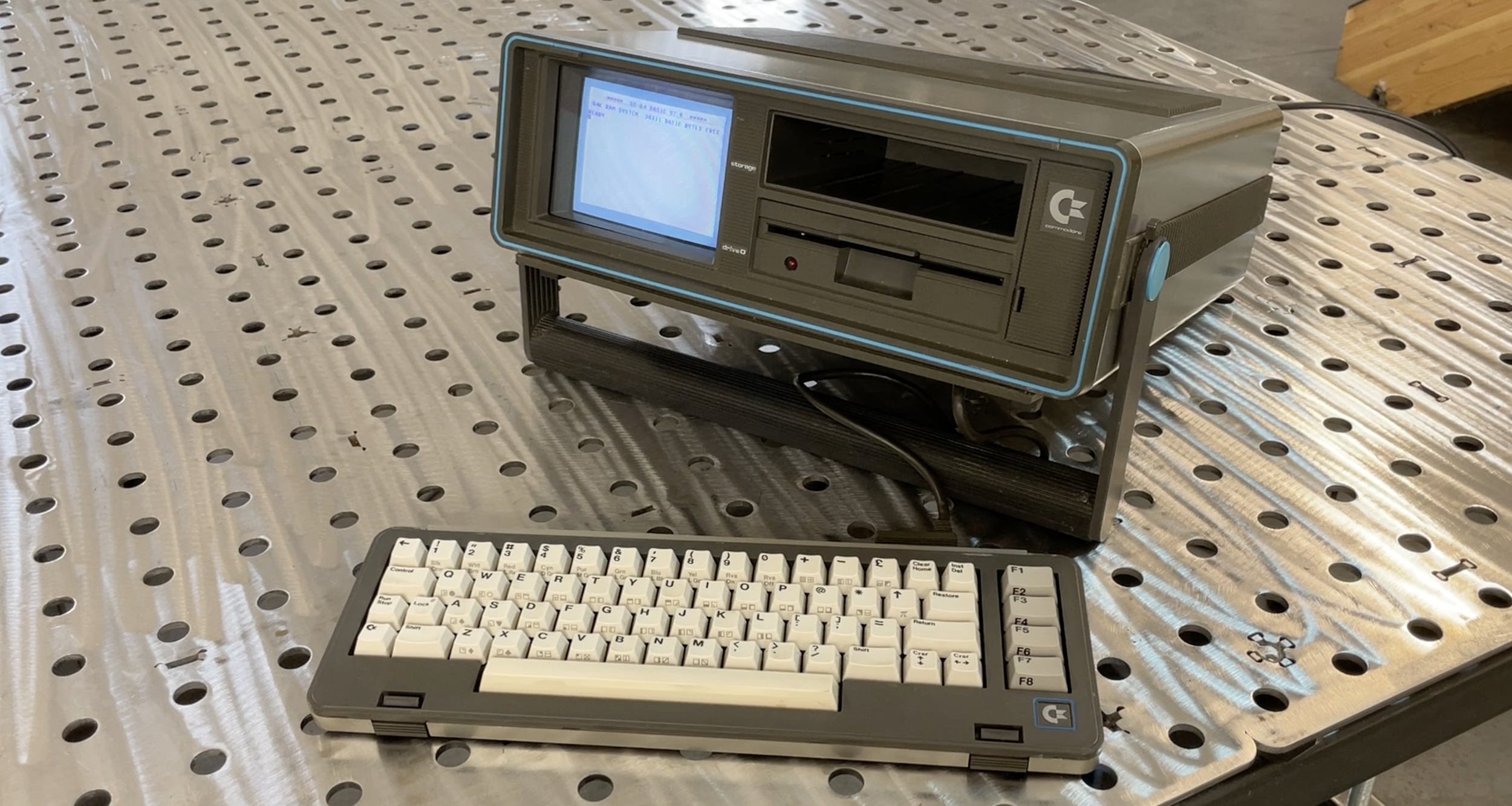
The Commodore SX-64, also known as the Executive 64, was a portable computer that was released by Commodore in 1984. It was designed to be a compact version of the Commodore 64, which was one of the most popular home computers of its time. The SX-64 was the first full-color portable computer with a built-in color monitor, making it a highly desirable machine for both business and personal use. Despite its relatively high price, it quickly gained a following among professionals who needed a portable computer for presentations and on-the-go work. Today, the Commodore SX-64 is considered a classic computer and is highly sought after by collectors and enthusiasts alike.

Acquisition
I bought my SX-64 on eBay in February of 2021. In College my first computer was a C64, and I remember seeing the SX computer in a specialty computer store at the time and thought it was pretty cool. Portables at the time were much larger than the SX, and none of them had color screens. The screen was reasonably readable, especially for a young guy.
This SX-64 was in very good condition. It's very common for machines on eBay to not have a keyboard cable and for the teal-colored endcaps on the handle to be missing. This computer was complete, so I paid a bit extra for it, although I don't remember what I paid.

Condition
When the SX-64 arrived, it was packed well, and when I started it up, everything worked pretty well except the keyboard. Several keys didn't work correctly, which is not uncommon for this computer after 30 years.
Visibly, the computer was nearly perfect, as it had all its parts. The most noticeable visual issue was the space bar, which was yellowed. I had noticed this in the listing but was sure it could be returned to its original appearance.

Keyboard
The keyboard problem is very common with this computer. The keyboard has a carbon membrane that sits between the key mechanism and the keyboard circuit board. There is a replacement manufactured by someone in Europe for around $25. So I went ahead and ordered a new one.
After taking the keyboard apart, I noticed that most of the internal standoffs that the keyboard mechanism screws to had been broken off. In addition, the standoffs that the keyboard connector screws onto had broken. Basically, there was very little holding the keyboard itself inside its shell. I had a sense of this, as the unit seemed to rattle a bit before I took it apart.
I decided to design and 3D print new standoffs for the keyboard socket on the back of the keyboard and for the mounts that hold the keyboard to the bottom half of the housing.
I filed down the remaining standoffs and 3D printed new versions. After a few iterations to get the sizes of the parts exactly correct, I used JB Weld to glue new parts in place. I think the new parts are actually much better than the originals as the originals had become quite brittle.
Since I had all the keycaps removed to get to the membrane, I individually cleaned all the keycaps with soap and water. The spacebar was pretty yellowed from UV light exposure. Interestingly, it seems that the space bar on a significant number of old computer systems I have restored seems to be made from a different plastic than the other keycaps and is often more yellowed than the other keycaps.
To correct the space bar color, I placed the space bar in Hydrogen Peroxide and placed it under a blacklight for 6 hours, and it returned to its normal color. I left all the keycaps on the kitchen counter overnight to dry. This turned out to be a mistake, as the next morning one of my Labrador Retrievers had retrieved the spacebar from the counter and was carrying it around quite proud of herself. Thankfully, only minor scars were present.
I developed a rule for myself a few years ago after other keyboard incidents. You only keep the caps off the keyboard for the absolute minimal time to prevent entropy accidents like this. Other times I've lost a key in the dishwasher and another in the garbage disposal. The sooner you figure out it's missing, the better!
Once I received the membrane, I reassembled the keyboard, and it worked flawlessly and looked like new (except for the small nick in the spacebar).
Link to the Keyboard Membrane replacement I used
Link to the STL file for the front keyboard standoffs I designed
Link to the STL file for the keyboard cable bracket I designed

LCD Screen and Audio Conversion
Researching the SX-64, I came across a series of Mods that people had done to replace the small color CRT with a 5.6 LCD Screen. The SX-64 was the first portable computer with a color screen. The original screen is a small Sony Trinitron CRT that works quite well, but due to its requirement for an electron beam shadow mask, it's just never going to be great.
The SX-64 and C64 were somewhat unusual for the time as they could provide separate Chrominance and Luminance signals to supporting monitors (essentially early S-Video).
That improved the signal quite a bit over composite video. The C64 used the Commodore 1701 and 1702 monitors to take advantage of these signals. The SX-64 also took advantage of these signals to provide a better image on the internal CRT.
The LCD mod was developed by an SX-64 enthusiast in Europe. He obtained a relatively inexpensive LCD display and controller from Alibaba. The display has composite inputs as well as chroma luma inputs. When connected to the SX-64, the picture is very good, and the size of the display is perfect for retrofitting into the case. The mod takes a minor firmware change to the controller.
I found someone who was selling the display and the modified controller on their website for $70 and decided to purchase it.
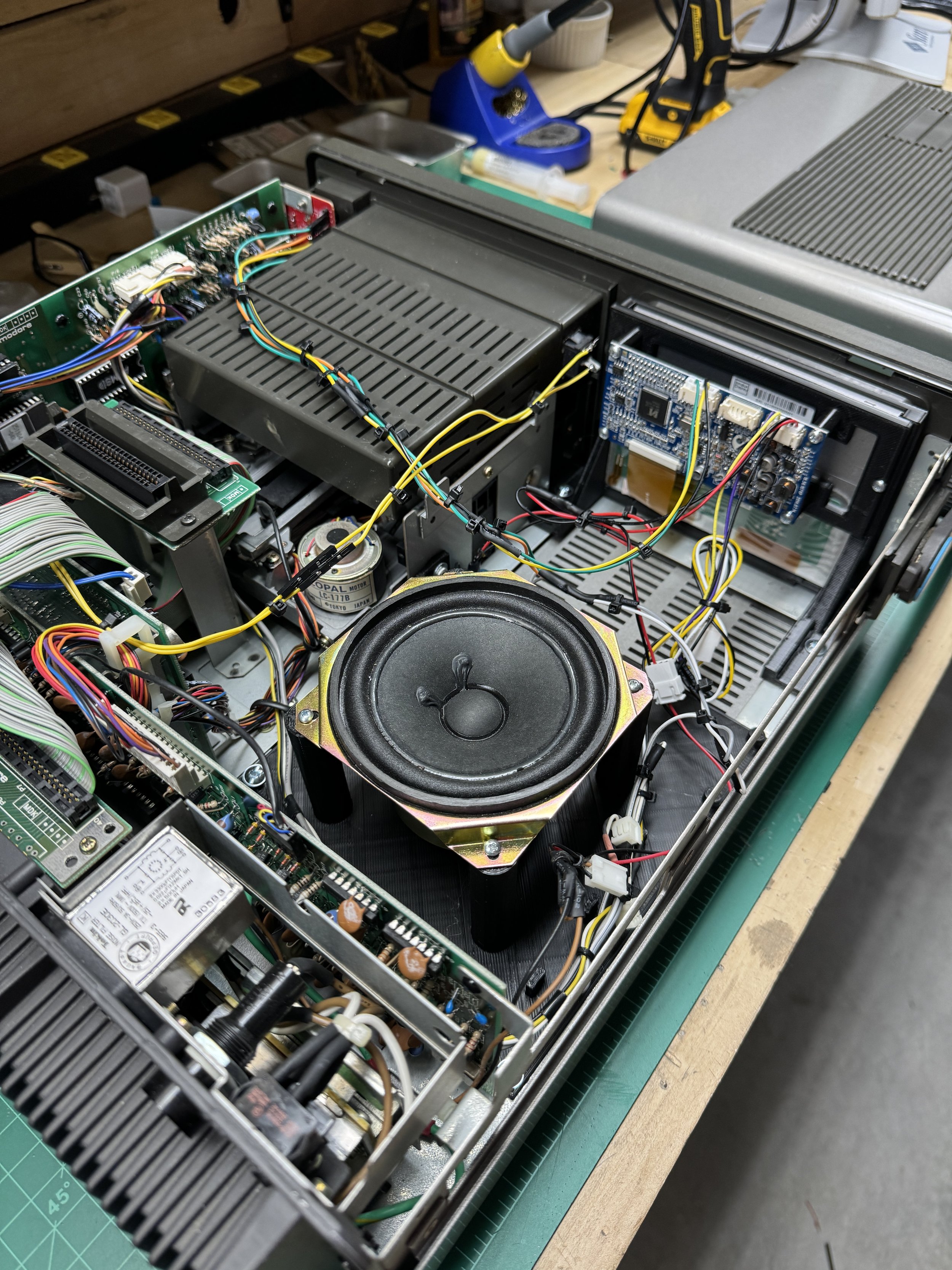
It took a while to receive the unit, but once it showed up, I proceeded to remove the CRT/Speaker unit from the machine, carefully documenting every step with photos. The CRT unit weighs quite a bit, making the machine a lot lighter with the LCD display, another added benefit of the LCD upgrade. I was careful to retain all the original parts in the event I wanted to put the machine back to stock. I doubt that I will ever do that, perhaps if I sell the machine someday, a buyer would prefer it in the original condition.
I removed one wiring harness that led from the image controls on the right side of the front of the unit and stored it with the CRT. I modified the 12V power connection to allow it to connect to the screen controller as well as a new audio amplifier I added.
The display has next to no documentation that comes with it, although there are a few videos on YouTube that people have made that are sufficient to get the display hooked up and working.
Link to replacement instructions and image adjustment control board
Link to replacement LCD Screen and Controller
Link to the video by Reviving Retro that I used to do the LCD replacement.

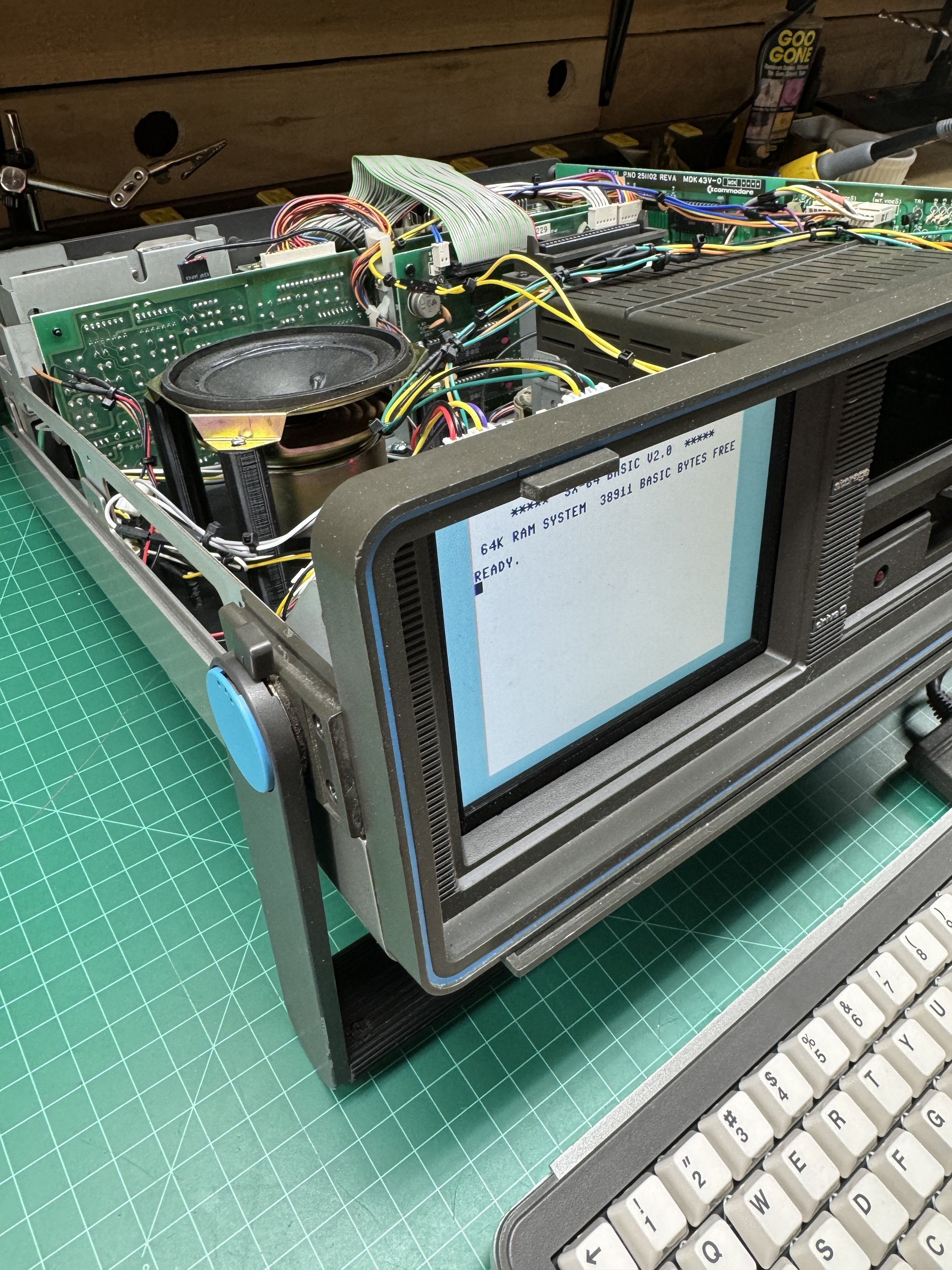
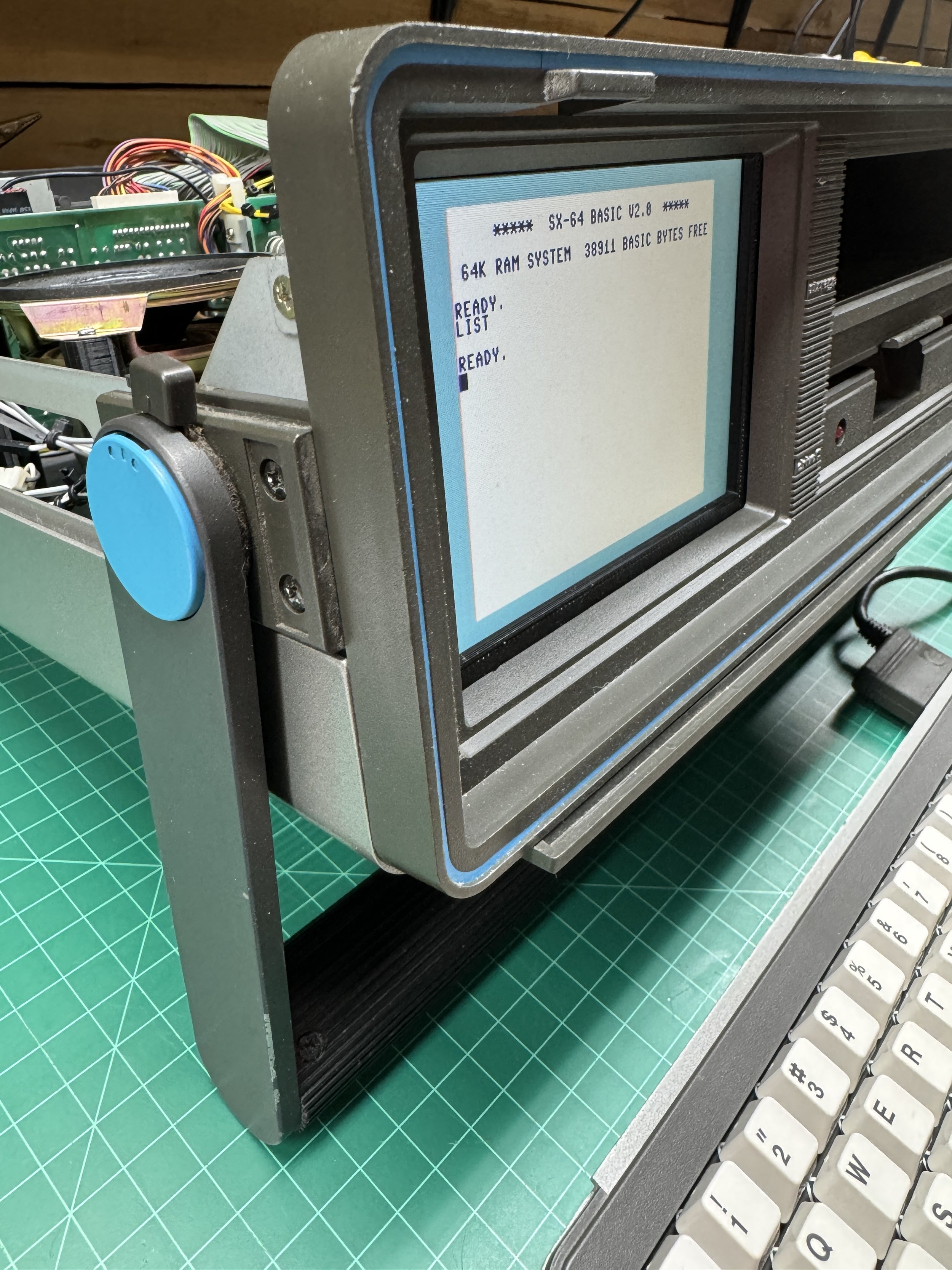
Mounting the LCD Screen
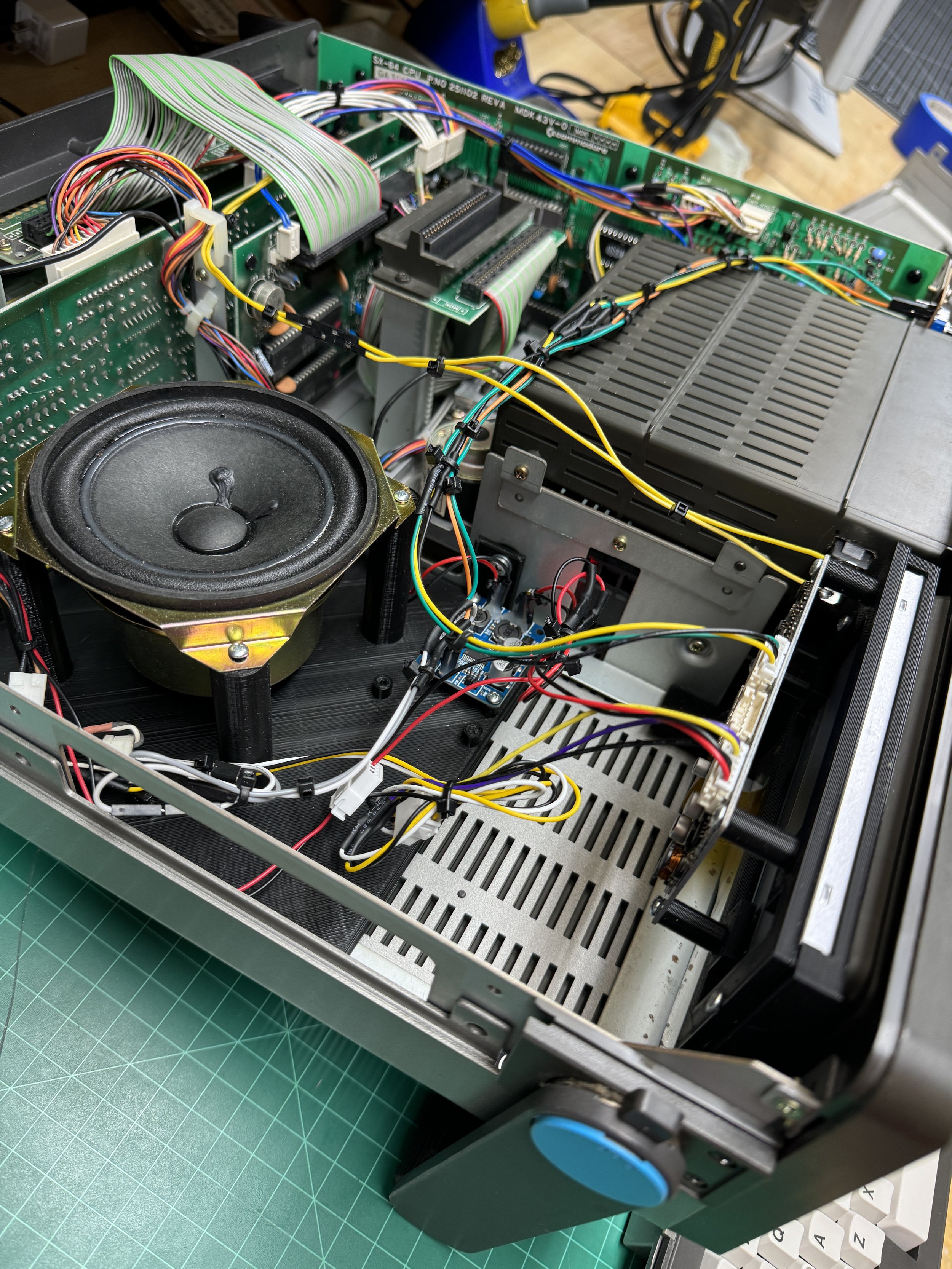
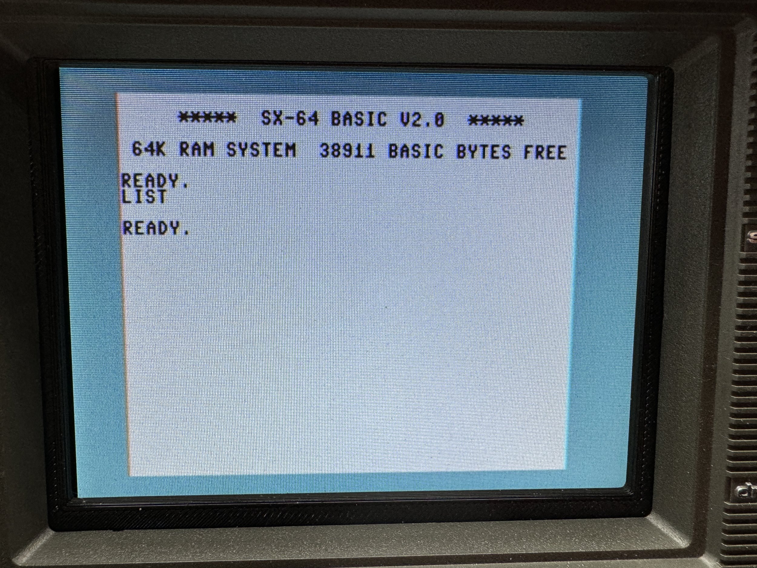
It is amazing how much better the LCD looks. At this point, I started working on a mounting scheme for the screen as well as a new speaker and amplifier board that I purchased on eBay inside the machine.
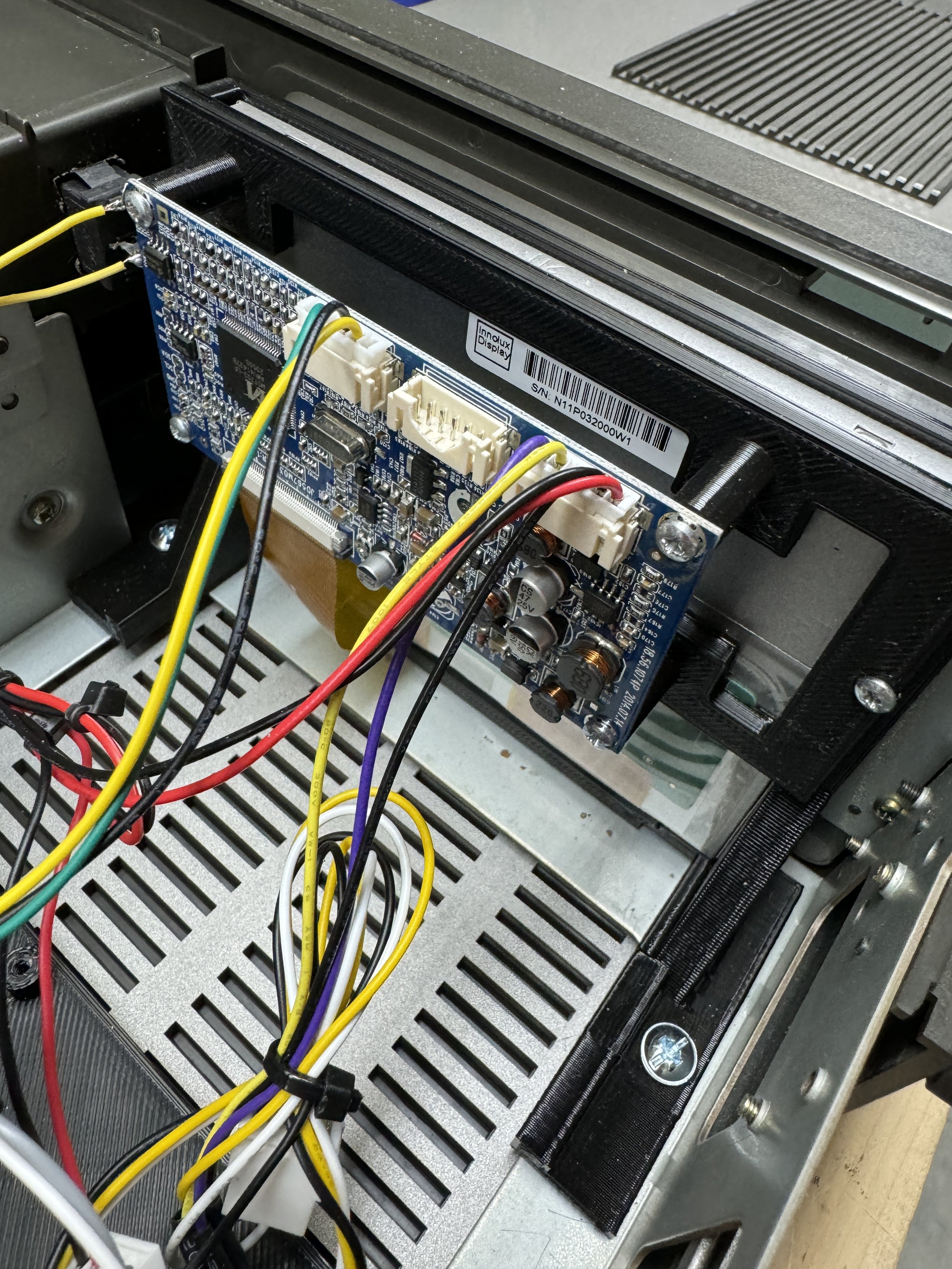
There are a few 3D designs available online for the screen mount. I printed one but didn't like how close the controller was to the screen. Also, tolerances in my chassis made the screen look slightly off skew when installed. I ended up designing my own mount, and it worked out fine after a few tweaks.
When the speaker and amplifier board arrived (both less than $10 each), I designed another mount for those that attaches to existing mounting holes in the chassis and installed everything. I hadn't done much with sound up until this point, so when I got it all connected back together, the sound was pretty faint. I did some debugging and googling, and the consensus on the internet was that the SID chip was failing.

Amplifier and Speaker Mount
I tried a small pre-amp to attach the volume potentiometer to, but I always got too much noise in the circuit for some reason. In the end, I used the potentiometer with an additional shunt resistor to set the volume range.
I needed a way to mount the speaker and the small amplifier board inside the now quite empty left side of the chassis. Using Sketchup, I designed a plastic insert to hold the parts in place using existing mounting holes in the chassis. The resulting unit was quite a bit lighter than the original.

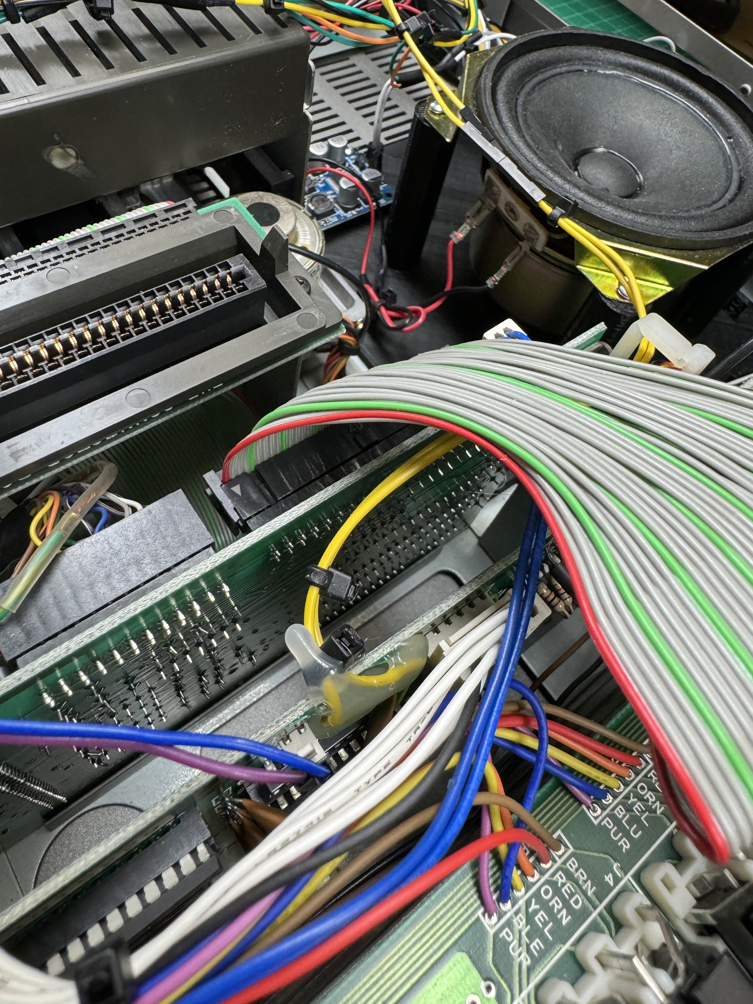
Replacing the SID Chip
The SID is a custom IC that was produced by Commodore/MOS and a common failure in C64's. After doing some research, I ended up buying a replacement called the ARMSID. It's a modern replacement that gets high reviews. That too was a Europe purchase, so that took a few weeks to arrive. Once installed in the system, surprisingly, it didn't make that much difference. After doing some more debugging, it turns out I had swapped the signal and ground inputs into the amplifier board that connect the SID output to the amplifier board.
Once that was straightened out, the sound worked great. So now I have an extra SID chip.
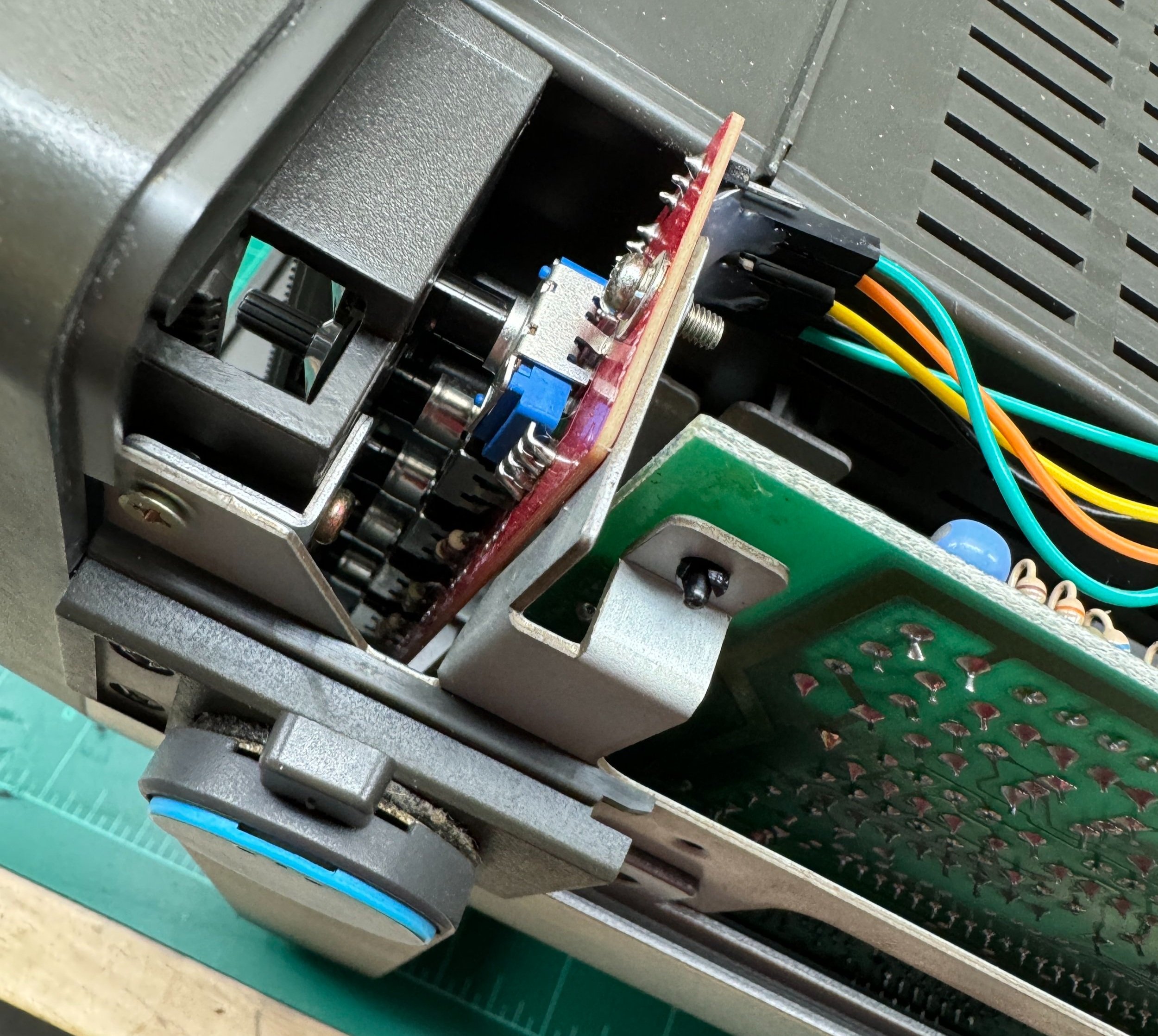
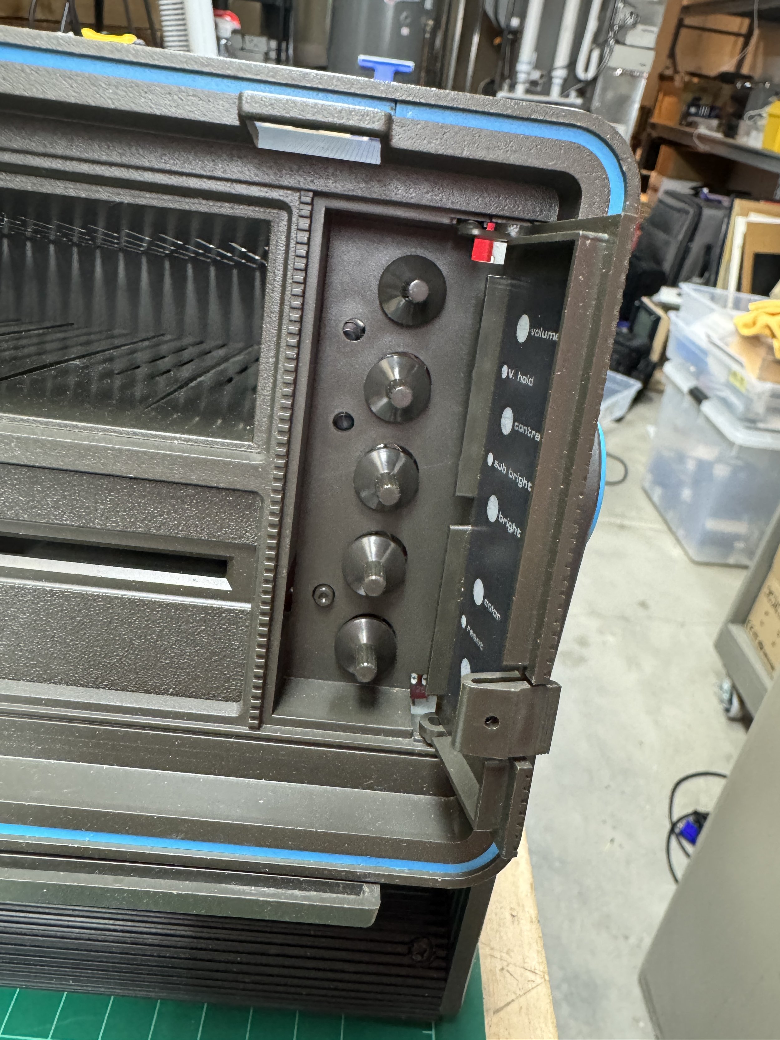
LCD Control Panel
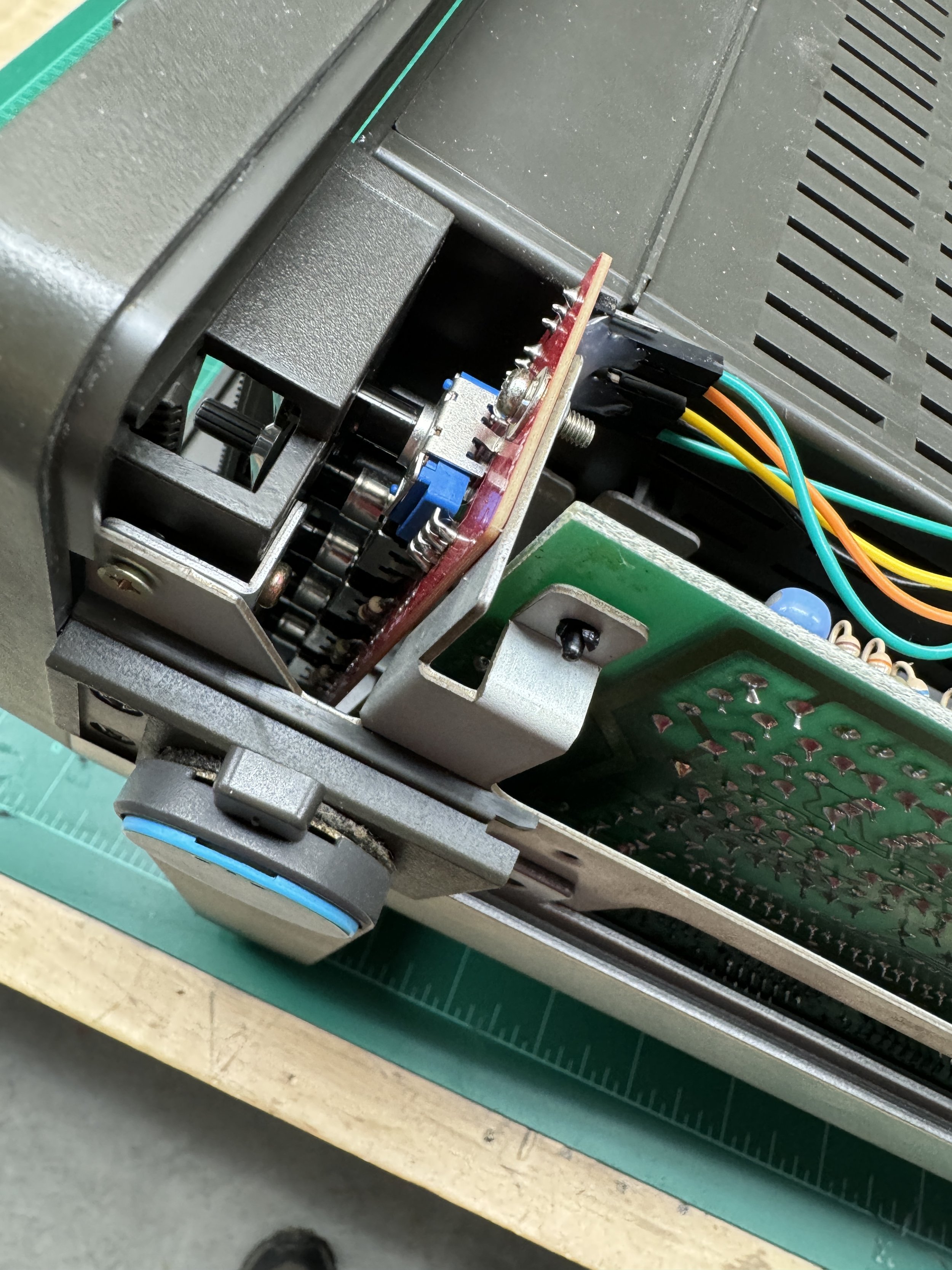
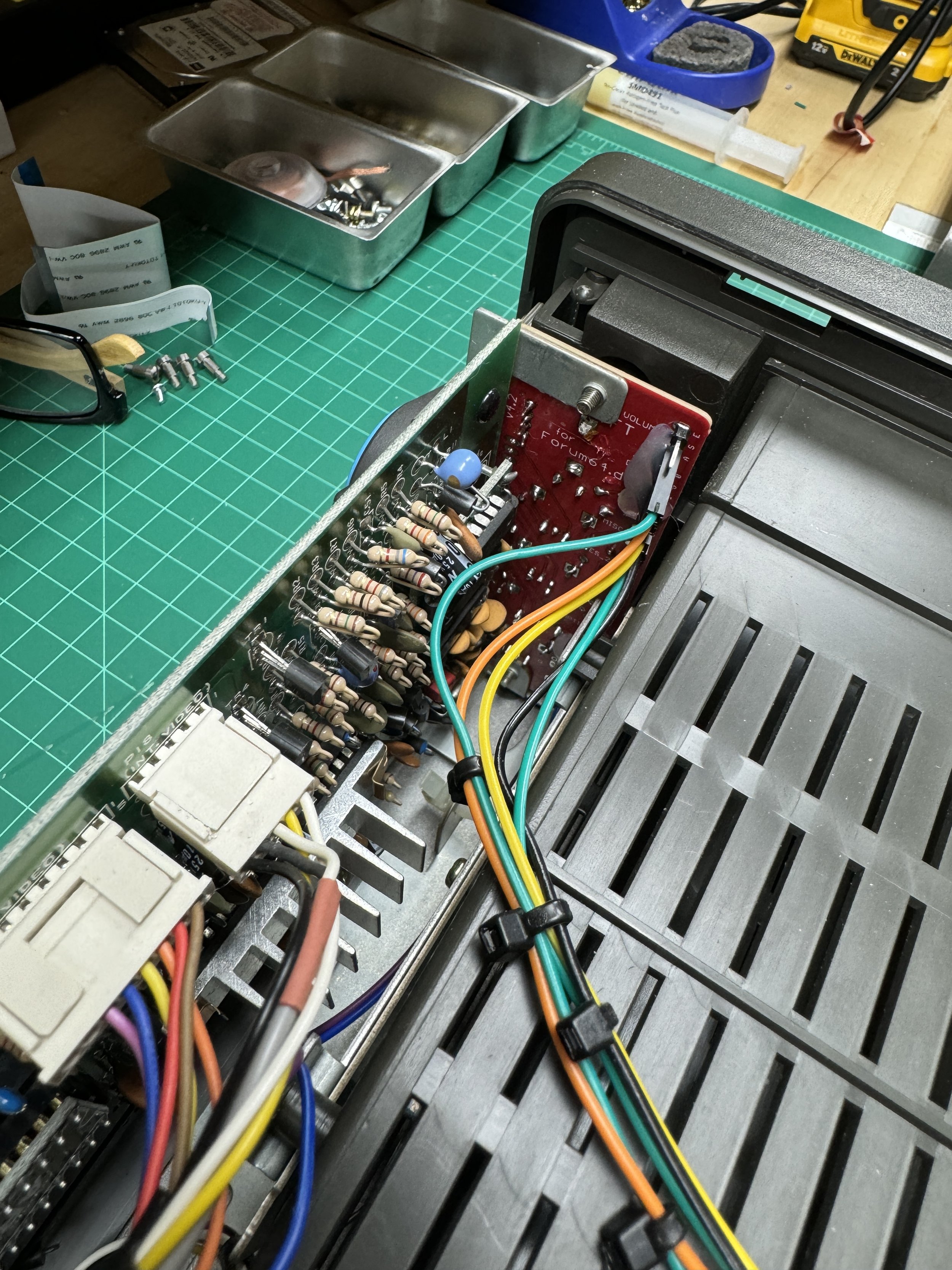
The LCD mod leaves the built-in controls on the right side of the unit largely unneeded (except for the speaker volume). Another enthusiast produced design is a replacement circuit board that mounts where the video controls potentiometers are located and allows you to control the settings on the LCD panel. At this point, I was kind of all in on the mod, so I ordered that circuit board from a board manufacturer and the components to populate the board from Mouser.
The board took about 6 weeks to receive, and the other parts about 1 day. When everything arrived, I soldered the components on the board and installed the board and tested. It worked fine to control the screen and the sound volume for the amplifier.
Link to replacement instructions and image adjustment control board

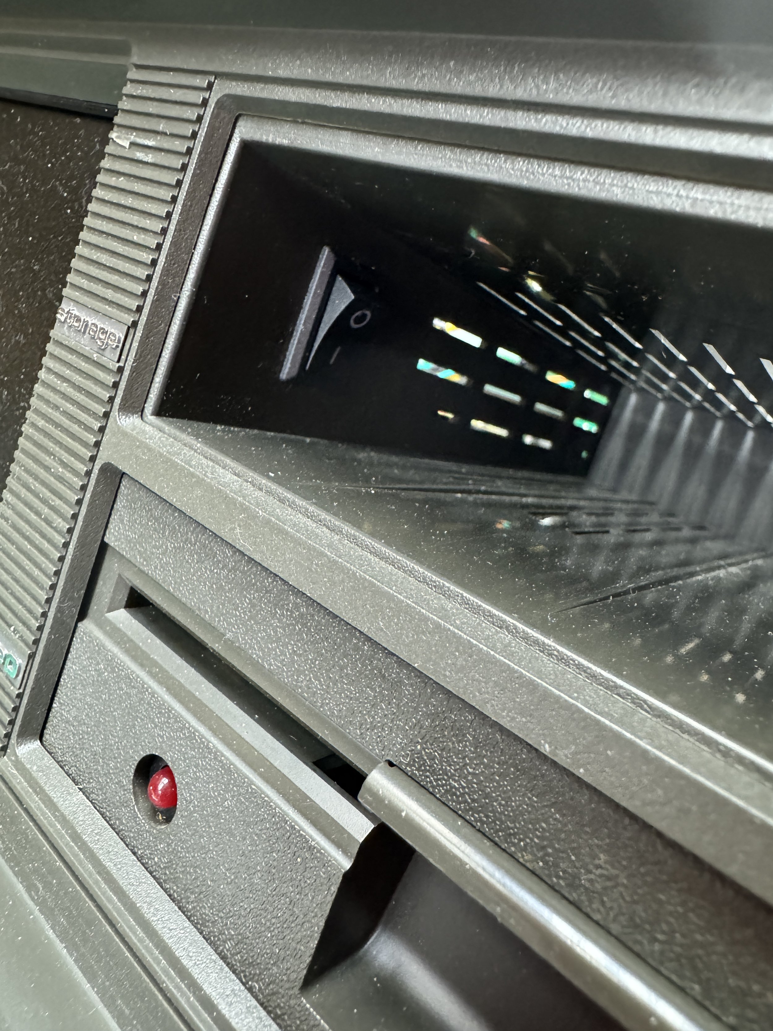
Adding a Drive select Switch
I really wanted to add a drive select switch to SX-64 to control the address of the internal 1541 floppy diskette drive. Most Commodore software expects to be run from Drive #8 that is the default for the internal drive. The problem here is that it's useful to connect a drive emulator to the 64 that runs software from a disk emulator. But to do this, the emulator generally needs to be drive 8. Many people put a switch right on the front of the unit to change the drive number of the internal drive. I don't like this approach as they generally put the switch in the cubby above the diskette drive. You need most of the space in that cubby to hold the keyboard cable when not in use. Lacking that space leads to losing that cable. Once you lose that cable, you have an issue.
I decided to use the cubby space for the switch but put the switch on the inside wall of the cubby. The lack of the CRT left room for this mounting style. It works great, and you can't see it in normal use, leaving the machine stock-looking. Connecting the switch to the diskette controller board is trivial and well-documented on the internet.

Conclusion
I like the SX-64. It's kind of cute. I love the LCD mod, and in fact, it makes the machine useful enough that I might sell my C64. The SX is much easier to move around and pretty much fully replaces anything I might want to do with the C64. I also believe the SX is more reliable than the C64. I have several C64's, in completely restored and several partially restored units.
I think the SX-64 was a bit of computer looking for a user when it was released. While some people used the 64's for business, most really just used them for games. The SX is clearly more of a business machine, and I'm just not sure how much business there was to do!
My SX is in excellent shape. I have the original parts, and to be honest, it's much more usable in its enhanced configuration.
Gallery