

Introduction: Using a Hobby-Ace Ublox GPS Module Built-in Compass With Arduino Uno

I recently found myself helping my son put together a High Altitude Balloon (HAB) for a school project and one of the things he acquired for the project was a Hobby-Ace Ublox GPS Module with Built-in Compass.
Originally this was designed to be used with Flight Control Boards similar to the ones you find on quadcopters or drones, so we figured we could make it work for our purposes too.
What we want to do is read all of the data from the 2 sensors and print them to the console. Later on in our project we will eventually save these values to an USB or SDCard, but we aren't there yet.... baby steps :)
Step 1: Gather and Prep Your Materials


Things you will need:
1) Arduino (I'm using an Arduino Uno, however most arduinos should be fine as long as they have a SDA/SCL pins)
2) Breadboard (Optional)
3) 10k Resistors or 3.3v-5v logic converter (prefered) (optional if you are using a 3.3v Arduino)
4) Wire
5) Hobby-Ace Ublox GPS Module with Built-in Compass (I got this on Amazon for around $15)
The GPS Module comes in a black plastic case, I had to remove the module from the case because we didn't know the color code for the wires. We couldn't find online anywhere a datasheet or schematic regarding this particular board (Our google-fu wasn't strong enough). However, if you purchase the same module or happen to already have one, you shouldn't need to remove the module from the puck because in the next step I'm going to give you the color code for the wires.
(Optional)
If you want to the remove the module, there are 4 phillips-head screws (size PH1, Here is a link on driver sizing if needed.) on the bottom of the puck. Remove the screws and the module just pulls out. The GPS module is just pressure fitted inside the plastic puck.
My GPS module also came with a couple of super small Molex connectors, we went ahead and cut those connectors (because we didn't have an adapter) and soldered the wires to a header pins.
Step 2: Wiring Everything Together


Once you have everything you need together let's start hooking everything up!
Now, in the photo above, we've attached a closeup picture of the breakout board that was inside the puck. we've also labeled the components we could identify... we're a n00b at this, so we couldn't identify much.
The one really nice thing about this board is the wires are correctly labeled on the board.
GPS Color Arduino
Black Ground GND
Red 5v 5v
Green TX PIN8
Yellow RX PIN9
Orange SCL PINA4
White SDA PINA5
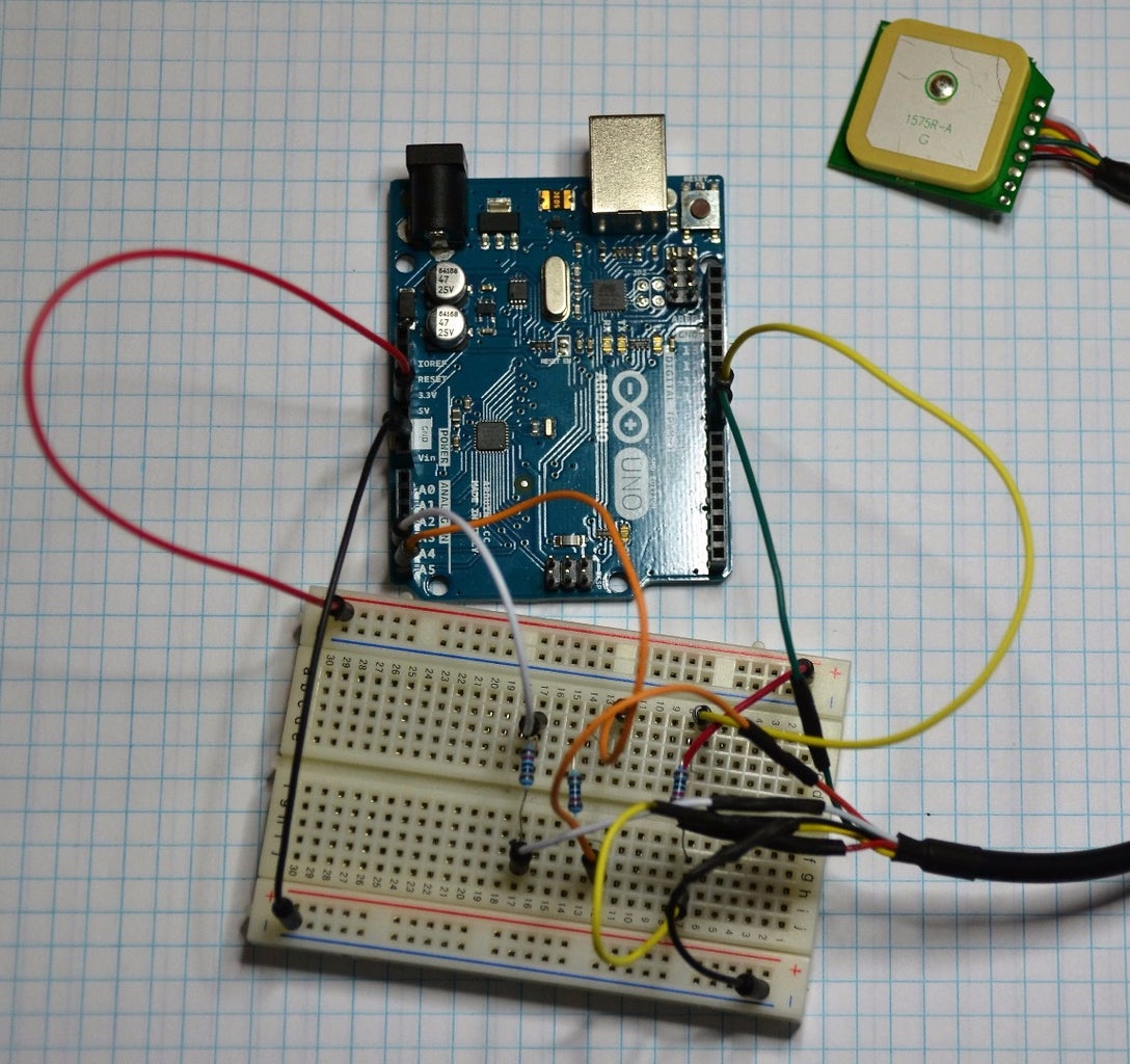
I've attached a wiring diagram that we mocked up using Fritzing, and a picture of what my own wiring looks like (yeah, it's not pretty, we'll clean it up once I get all the other sensors we want attached and working).
One thing we wasn't sure of is if this board provides 5v to 3.3v level shifting for the data pins, so to be on the safe side, we added 10k resistors to each of the relevant data pins to ensure we didn't burn anything up, when we finalize everything we will be adding 3.3v-5v logic converters instead of the resistors.
One additional thing to note, the Green/Yellow(tx/rx) use a serial connection while the Orange/White(SCL/SDA) use the i2c connection. If you are using another type of Arduino, your connections might be different, so you need to adjust accordingly.
Step 3: The Code!
We used the Adafruit Sensor library and HMC5883 Sensor library for the Compass sensor and the TinyGPS++ library for the NEO-6m GPS Module.
We won't copy and paste the code in the instructions because we have attached the source code file, but we will go over a couple of the more interesting lines within the code.
Since the tx/rx of the GPS Module need to be reversed when hooked up to the Arduino, we declare those pins in Line 14. So essentially the TX wire from the GPS needs to go to the RX pin on the Arduino and the RX wire from the GPS needs to go to the TX pin on the Arduino.
static const int RXPin = 8, TXPin = 9;
The default BaudRate for the NEO-6m Module is 9600. So we made sure to declare this in line 15.
static const uint32_t GPSBaud = 9600;
The Magnetic Compass Module needs to be calibrated for your location!!
I've included more detailed instructions on how to do that in the code comments.
  // Once you have your heading, you must then add your 'Declination Angle', which is the 'Error' of the magnetic field in your location.<br>  // Find yours here: <a href="http://www.magnetic-declination.com/"> http://www.magnetic-declination.com/
</a>  // Now convert your degrees/minutes/seconds to decimal form.
  // then convert the decimal form to radians.
  // Mine is: 3* 18' E, which is +3.3 Degrees, or (which we need) 0.0575959 radians
  // If you cannot find your Declination, comment out these two lines, your compass will be slightly off.
    float declinationAngle = 0.0575959;
    heading += declinationAngle;
To find your magnetic declination you goto to the link in the code above.
Once you have your magnetic declination in Degrees and Minutes you need to convert that into decimal form. Which you can do here: http://www.rapidtables.com/convert/number/degrees-...
Now that you have your magnetic declination you can convert that into Radians which is what the Adafruit library requires. This can be done easily by google: https://www.google.com/webhp?q=1%20degrees%20to%20...
Make sure you change line 140 to the correct declination in radians for your location!
We've made sure to comment the code the best could in order to help you set everything up and customize your setup.
I highly suggest you take a look at the Reference Step of this Instructable and read more about Heading location and the TinyGPS++ Library!

Step 4: Profit!

Once you have your code uploaded to your Arduino, and everything plugged in.... Connect your Arduino to your computer and open the Serial Monitor and you should see the information scrolling across your screen!
This GPS Module does NOT work indoors, so if you want to see your location, you need to go outside, it also could take anywhere from 2-5 minutes for it to properly track the GPS satellites and give you the correct position.
Step 5: Additional Resources!
Adafruit HMC883L Wiring/Code example - https://learn.adafruit.com/adafruit-hmc5883l-break...
Honeywell Document on using Compass Heading Using Magnetometers - https://www.adafruit.com/datasheets/AN203_Compass_...
TinyGPS++ Website - http://arduiniana.org/libraries/tinygpsplus/
NMEA Sentence Information - http://aprs.gids.nl/nmea/
Thanks for reading and good luck on your build!

![Tim's Mechanical Spider Leg [LU9685-20CU]](https://content.instructables.com/FFB/5R4I/LVKZ6G6R/FFB5R4ILVKZ6G6R.png?auto=webp&crop=1.2%3A1&frame=1&width=306)


