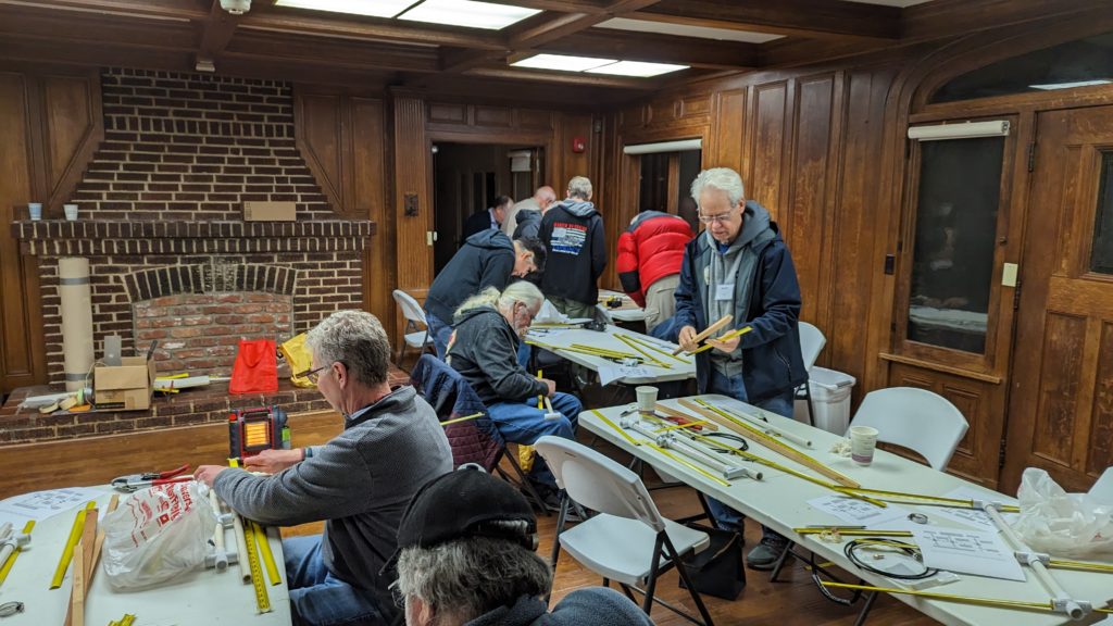
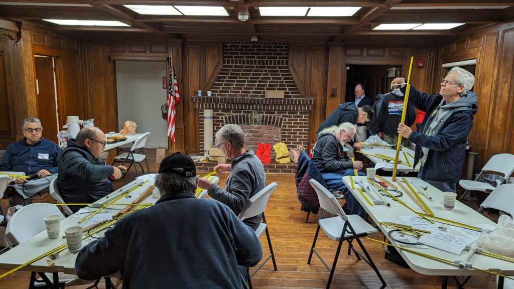
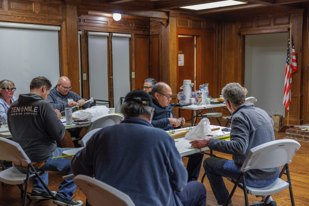
At our February 2023 membership meeting, the South Pasadena Amateur Radio Club organized a group building project. We constructed 2 meter tape measure antennas ideal for radio direction finding or “t-hunting.” The club provided a kit of necessary parts to all dues-paying members who wished to participate.
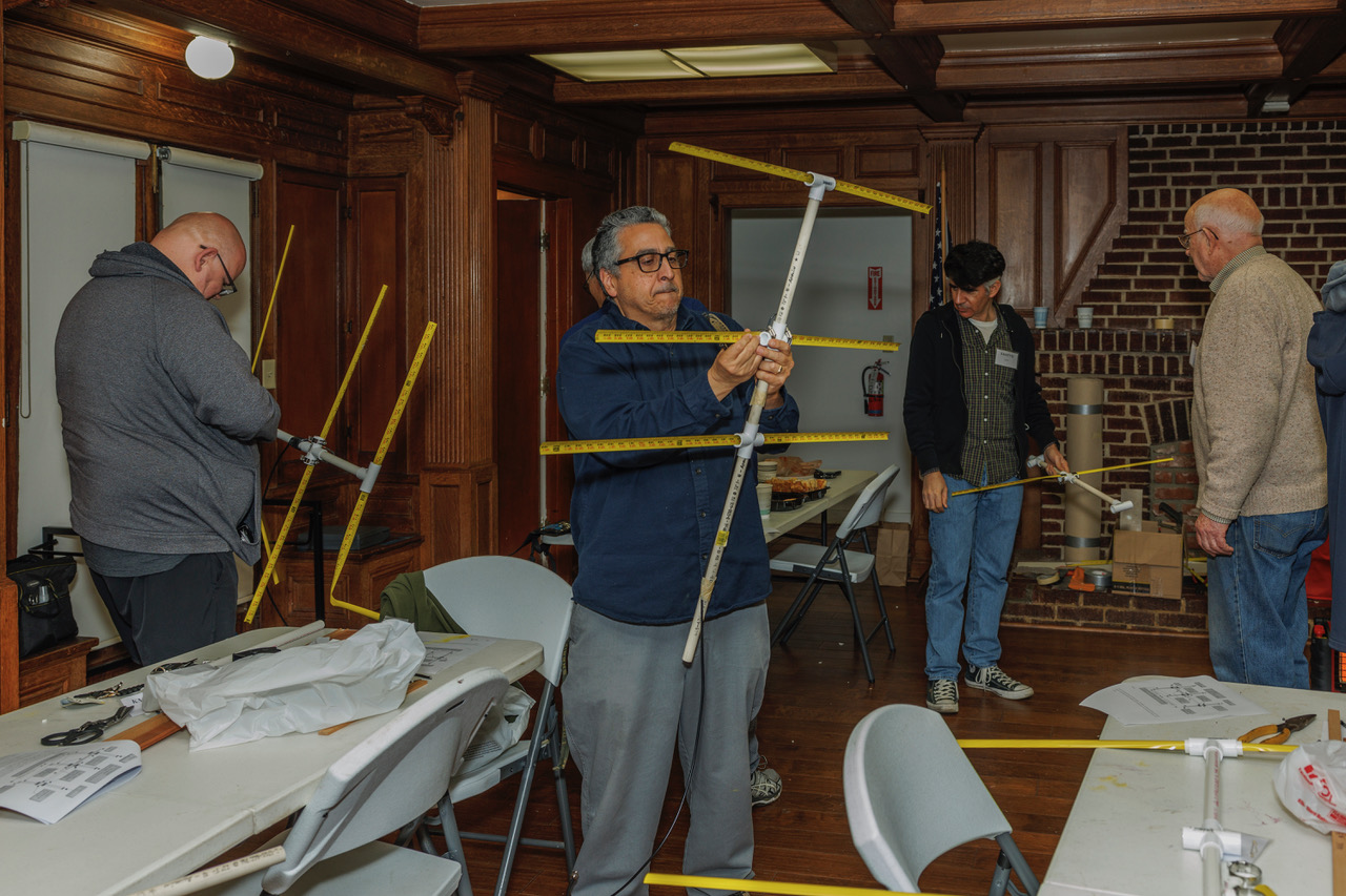
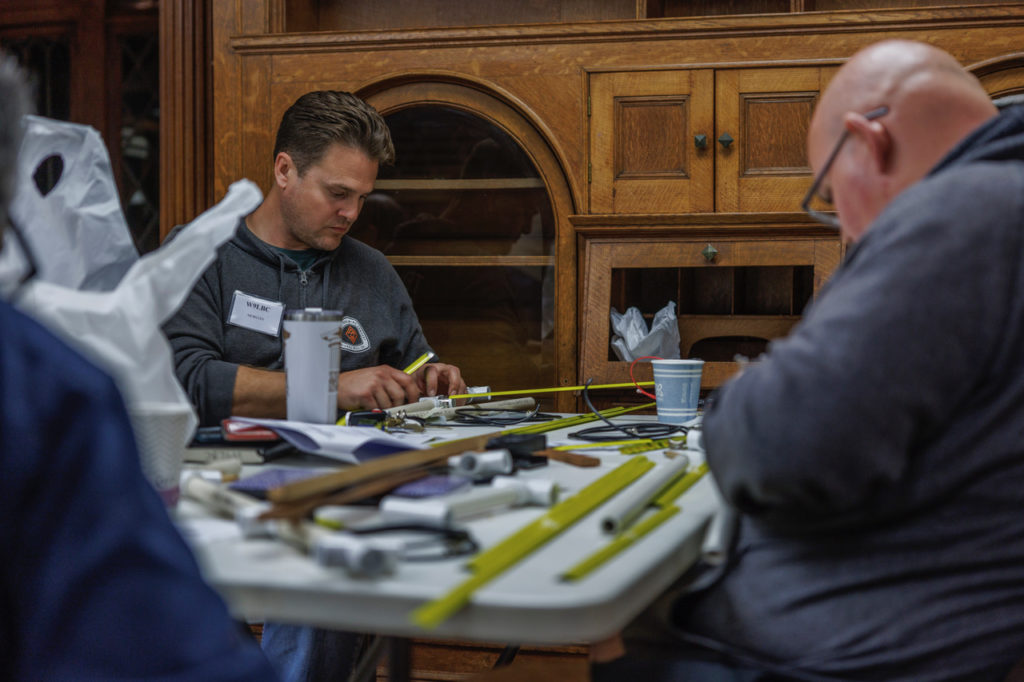
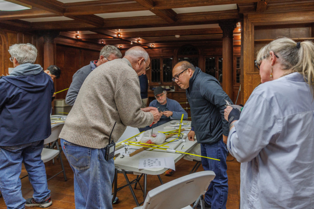
The project was led by Bob WB6YJJ, Rick KI6ZKM, and Stan KR6CV, who provided instruction and assistance as members assembled the antennas. The process involved measuring and cutting tape measure segments to the correct length, assembling a frame from PVC pipe sections, then soldering the components of the driven element (the part of the antenna that radiates).
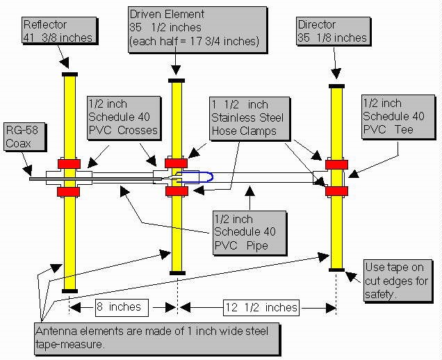
There are various plans for similar tape measure beam antennas, or “cheap Yagis,” available on the Internet. Here is the schematic for the one we built, designed by Joe Leggio WB2HOL:
Visit Joe’s page linked above or this re-post for a full explanation of how the antenna works and instructions for building one.
Below are photos of all the steps in the building process, courtesy of Robert K6YZF, Stan KR6CV, and John KK6ZVQ.
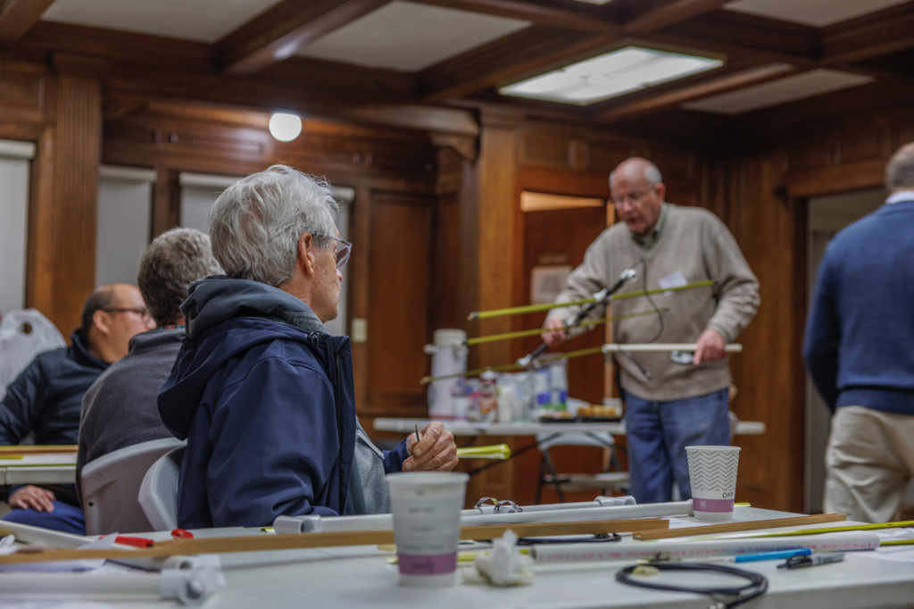
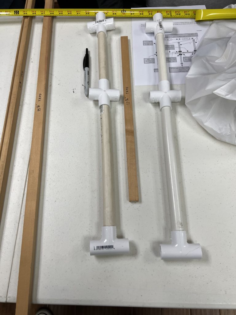
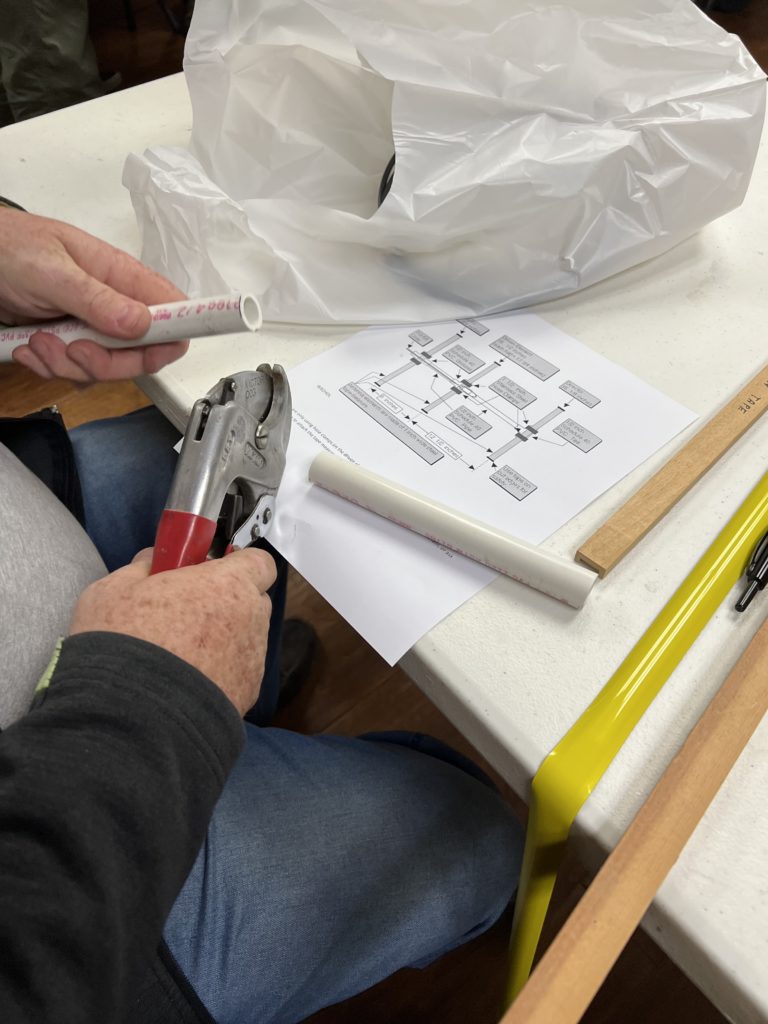
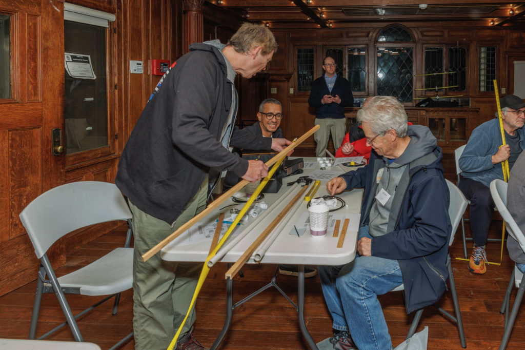
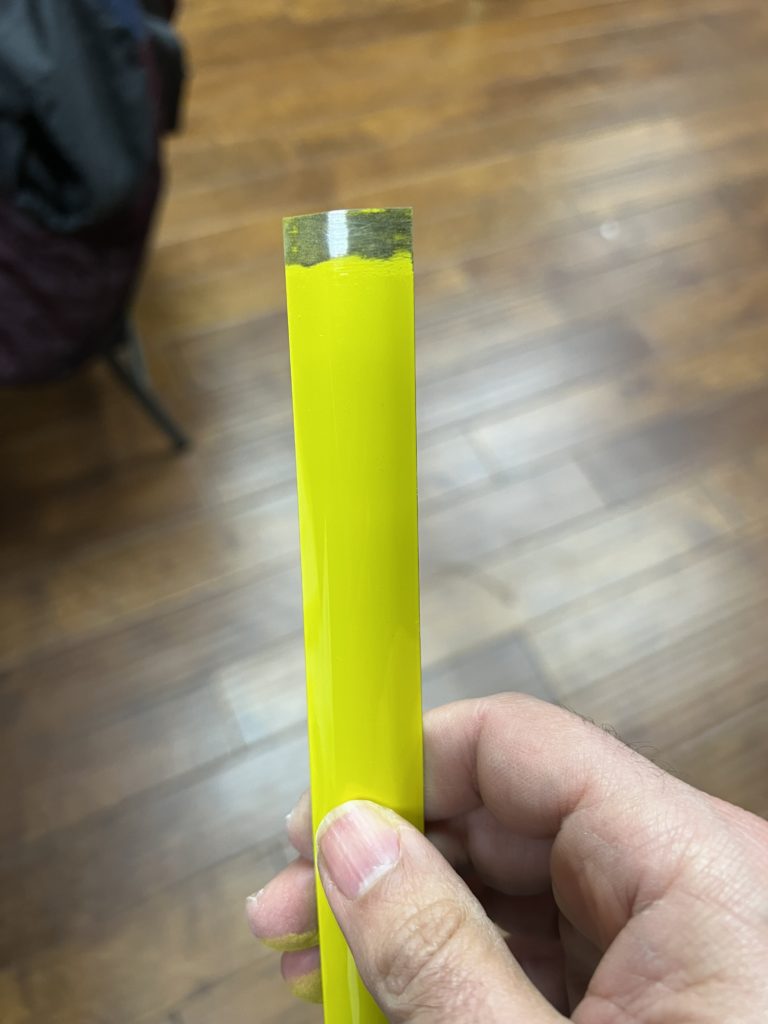
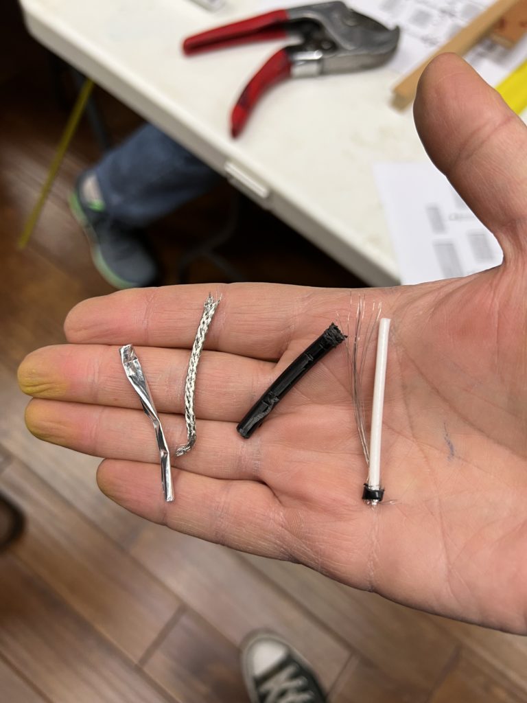
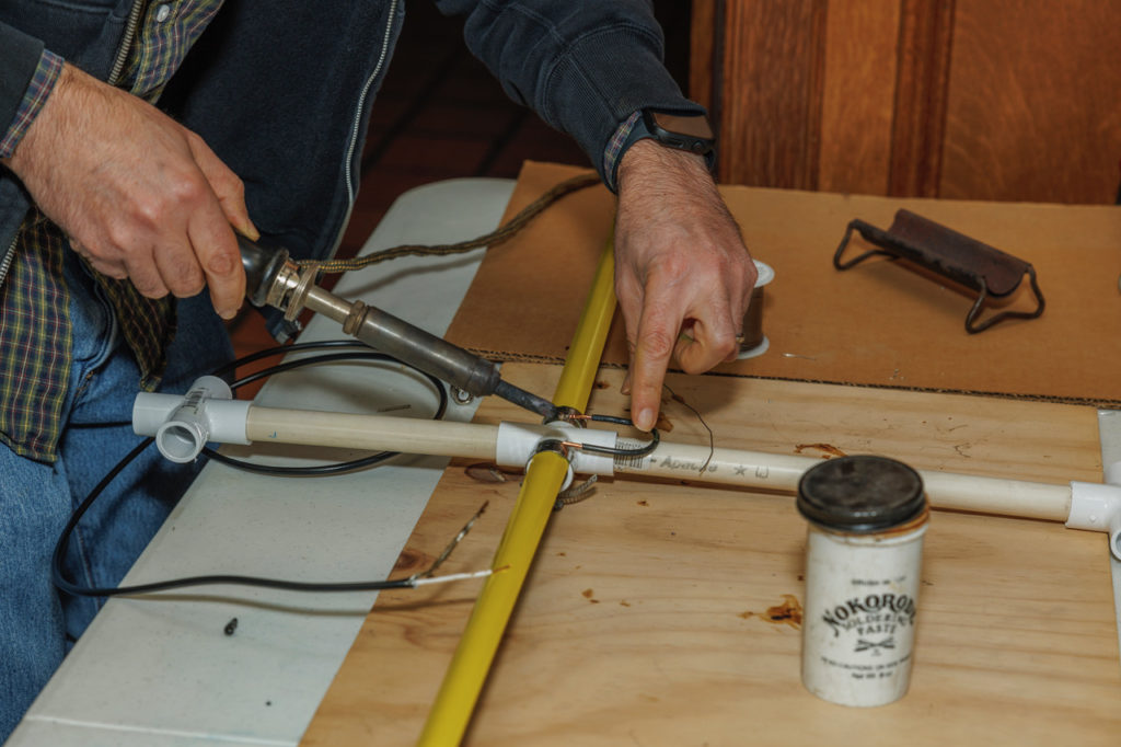
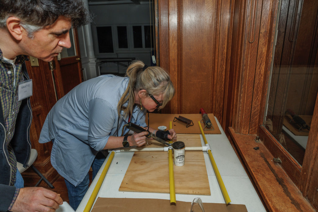
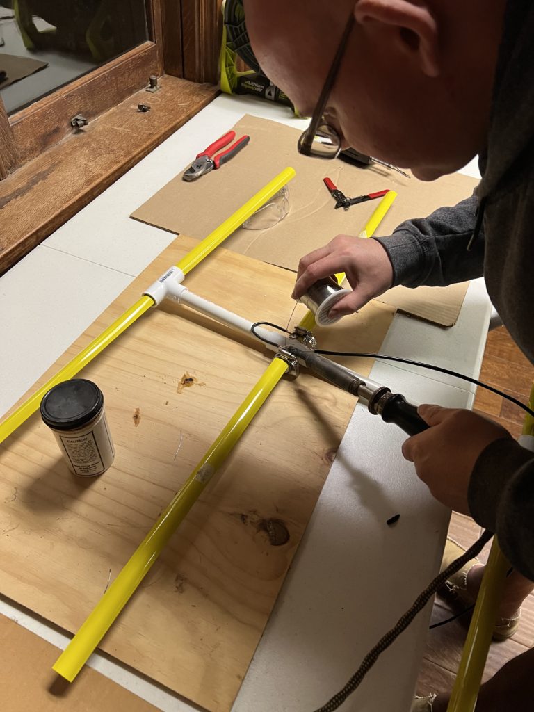
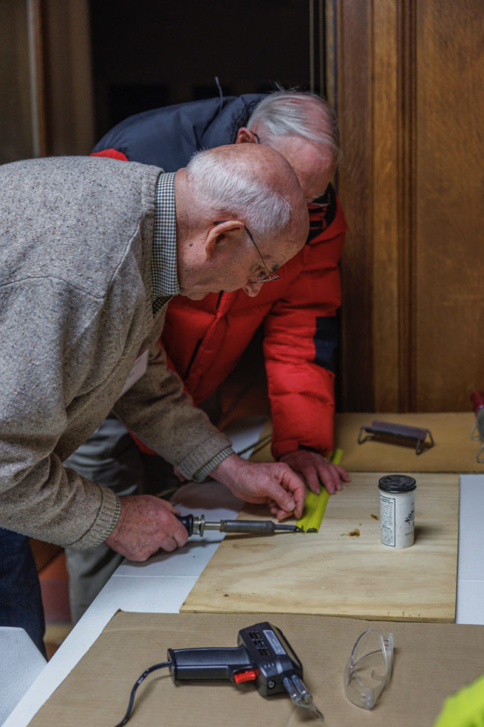
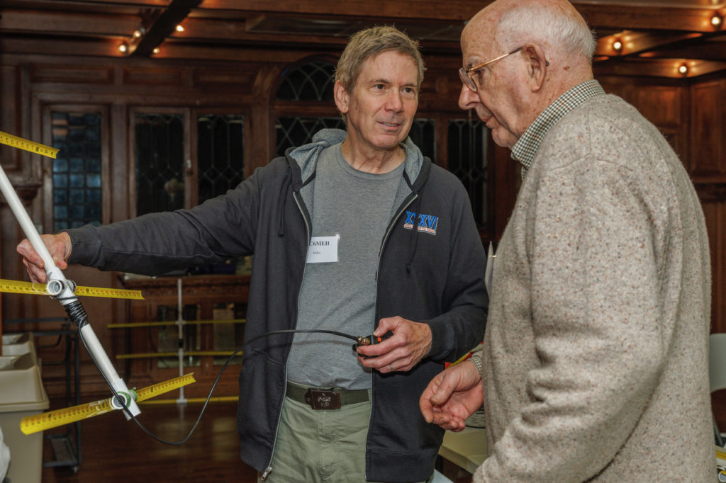
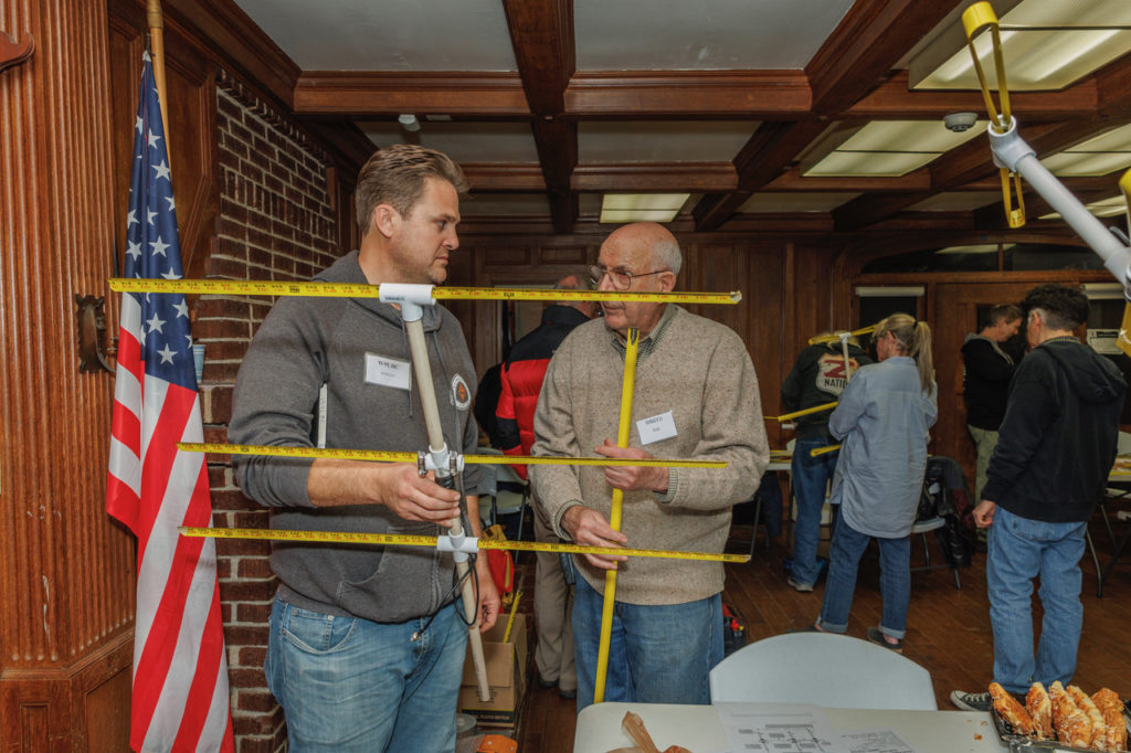
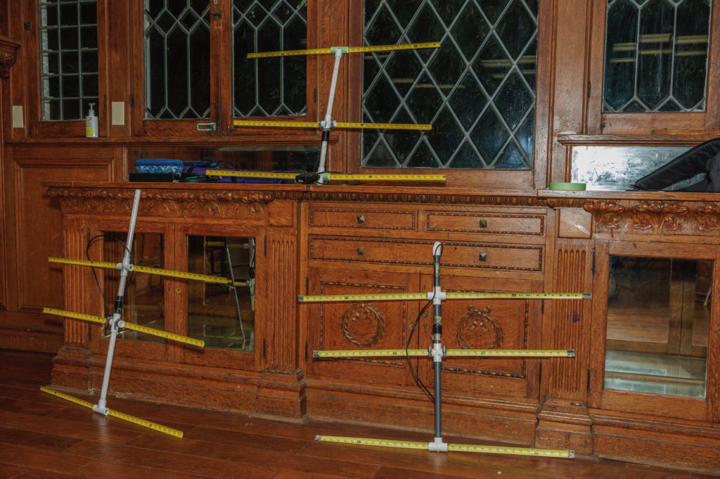
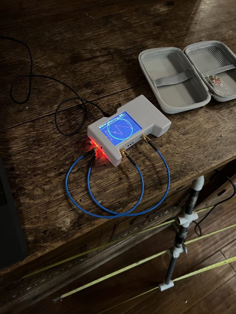
Bob Vanderwall, WB6YJJ demonstrates the 2 meter tape measure Yagi for the builders.“Story stick” templates for cutting the PVC pipe and tape measure segments.Once the PVC segments have been measured and marked, they are cut with a pair of ratcheting PVC cutters.The tape measure segments can be cut with a pair of tin snips or heavy duty scissors.The center pair of tape measure segments form the antenna’s driven element. In order to create an electrical connection, you must sand off some of the yellow paint on those segments. Inserting the tape measure segments into the PVC frame.Splitting the antenna’s coaxial cable is necessary to expose the pieces that get soldered to the central tape measure segments.Stripping coax is a delicate operation. Apply too much pressure, and you may end up with useless bits. A close view of the soldering step.K6XIX solders the central tape measure sections to form the driven element.The two halves of the driven element are connected by a U-shaped wire.Bob WB6YJJ solders the driven element’s components.Five turns of the coax cable around the PVC frame form a common mode choke.W9LBC and WB6YJJ discuss how to optimize the antenna’s performance.Three completed tape measure beams.Once completed, the antennas were tested with an antenna analyzer or a NanoVNA, above, to measure their SWR.
This building activity was a welcome return to hands-on projects at our meetings, and we look forward to hosting more in the future.